Article

Modeling and Design of a Novel 5-DOF AC–DC Hybrid Magnetic Bearing

Faculty of Automation, Huaiyin Institute of Technology, Huai’an 223003, China
*
Author to whom correspondence should be addressed.
Appl. Sci. 2022, 12(18), 8931; https://doi.org/10.3390/app12188931
Submission received: 5 July 2022 / Revised: 1 September 2022 / Accepted: 1 September 2022 / Published: 6 September 2022

Abstract

:
This paper investigates a novel integrated AC–DC hybrid magnetic bearing (HMB) to reduce the volume, weight, manufacturing, and operation cost of magnetic suspension motors. Two radial MBs and an axial MB are integrated with the proposed HMB. The five-degree-of-freedom (5-DOF) suspension is realized in one unit. Two axially polarized permanent magnets provide the radial and axial bias fluxes. First, the HMB structure and the suspension mechanism are introduced. Second, based on the method of equivalent magnetic circuits, magnetic circuits are calculated. The mathematical models of suspension force are discussed. Third, the main parameters of the 5-DOF AC–DC HMB are given. The 3D finite element method (FEM) is adopted to analyze the proposed system’s electromagnetic characteristics, and the suspension mechanism of the 5-DOF is verified. The radial suspension forces versus the radial control current, the axial suspension forces versus the axial control current, the relationship between the axial suspension force and the axial control current with the X direction offset, and the relationship between the radial suspension force in the X direction and the axial control current with the Z direction offset are calculated. Based on the research results, it is shown that the HMB structure is compact and reasonable, and the mathematical models and suspension mechanism are correct.

1. Introduction

Currently, with the increase of rotor speed, the requirements for bearing performance are getting higher and higher. New types of bearings such as air-floated bearings, liquid-floated bearings, and magnetic bearings (MBs) have been employed. The friction between the rotor and bearing is reduced in high-speed electric machines supported by air-floated or liquid-floated bearings. However, special air-floated and liquid-floated equipment is required, which makes the motor system bulky, complicated in structure, and increased in cost. Moreover, there are inevitable problems of air and liquid leakage that prevent their use in pollution-free, ultra-clean special electric drives. MBs supported by electromagnetic force are new types of non-contact bearings. They have the advantages of no wear and lubrication, low vibration and noise [1,2,3,4,5,6,7,8,9], and can achieve higher rotor speed and power operation. Therefore, special machines use MBs, such as vacuum pumps, blood pumps, and heart pumps [10,11,12,13].
Commonly, thrust MBs are adopted to control the axial directional translation. The radial two-degree-of-freedom (2-DOF) MBs are employed to control the two radial directional translations [14]. A 3-DOF MB is used to control the axial directional translation and two radial tilting motions [15,16]. Recently, several studies have been proposed to develop the structures of MBs. In [8], a slice of 5-DOF four-pole MB was studied. The structure is compact. However, it is driven by DC power amplifiers, resulting in a bulky and costly system. In [17], a 3-DOF MB with a biased permanent magnet was designed and applied to a high-speed motor. Compared with the MBs using only solid magnetic materials, a laminated radial stator was applied in the 3-DOF MB to reduce eddy currents. Considering the eddy-current effects and leakage effects, an accurate mathematical model was established. Meanwhile, in [18], a 3-DOF MB was designed and optimized with a hierarchical multiobjective optimization structure to improve both the radial and axial suspension. However, a large thrust disk causes many problems such as speed limitation, increased rotor unbalance, and rotor dynamic performance degradation.
In [19], a novel four-pole 4-DOF MB with two active parts and one passive part was proposed. The structure of the 4-DOF MB was compact, so the size and power consumption were reduced. However, due to the application of four permanent magnets, the 4-DOF MB has high costs and is difficult to manufacture and assemble [20]. Moreover, because the axial single DOF is passively stabilized by reluctance forces, the axial load-carrying capacity is limited, and the output power of the motor is low. It is only suitable for applications where the axial impact and motor output power are small. Commonly, a full magnetic suspension drive system needs axial MBs, radial MBs, or radial–axial MBs, and a high-speed electric machine [21,22,23]. A combined structure of two or three MBs results in a rather long axial length of the rotor shaft and makes the structure complicated. It has low axial utilization, critical speed, and power density. Compared with bearingless motors such as bearingless permanent magnetic motors [24] and bearingless flux-switching permanent motors [25], combined structures have obvious advantages in terms of simple control and small coupling [26,27].
In addition, traditional MBs generally have an eight-pole or four-pole structure [28,29,30]. The radial 2-DOF MB is driven by four unipolar or two bipolar DC power amplifiers. The whole MB system is bulky and costly [31,32]. In order to reduce the size and save cost, a three-pole MB was proposed. At present, three-pole MBs mainly use two driving modes, namely a three-phase power inverter drive [33,34,35] and a DC power amplifier drive [36]. In comparison with DC MBs, AC MBs can effectively reduce the number of inverters, system volume, and cost [37,38].
This research proposes a 5-DOF AC–DC HMB with permanent magnets to increase the critical speed of high-speed electric machines, especially in high-speed mechanical systems. The proposed HMB can realize 5-DOF in one unit. Three-phase power inverters are employed for the radial drive, while DC power amplifiers are used for the axial drive. The radial and axial control fluxes do not interfere with each other. The structure of the inclined axial magnetic poles reduces the axial length of the rotor and is beneficial to improving the critical speed of the rotor. It has a series of advantages such as low cost, low power consumption, and compact structure. The structure and working principle of the proposed 5-DOF AC–DC HMB are first introduced. Then, the equivalent magnetic circuit method is employed to deduce the mathematical models of suspension forces. Based on the finite element analysis (FEA), the electromagnetic properties of the 5-DOF AC–DC HMB are analyzed, including the radial suspension forces versus the radial control current, the axial suspension forces versus the axial control current, flux field distributions, and the relationship between the suspension force and the control current with the offset, all of which verify the correctness of the theoretical analysis.

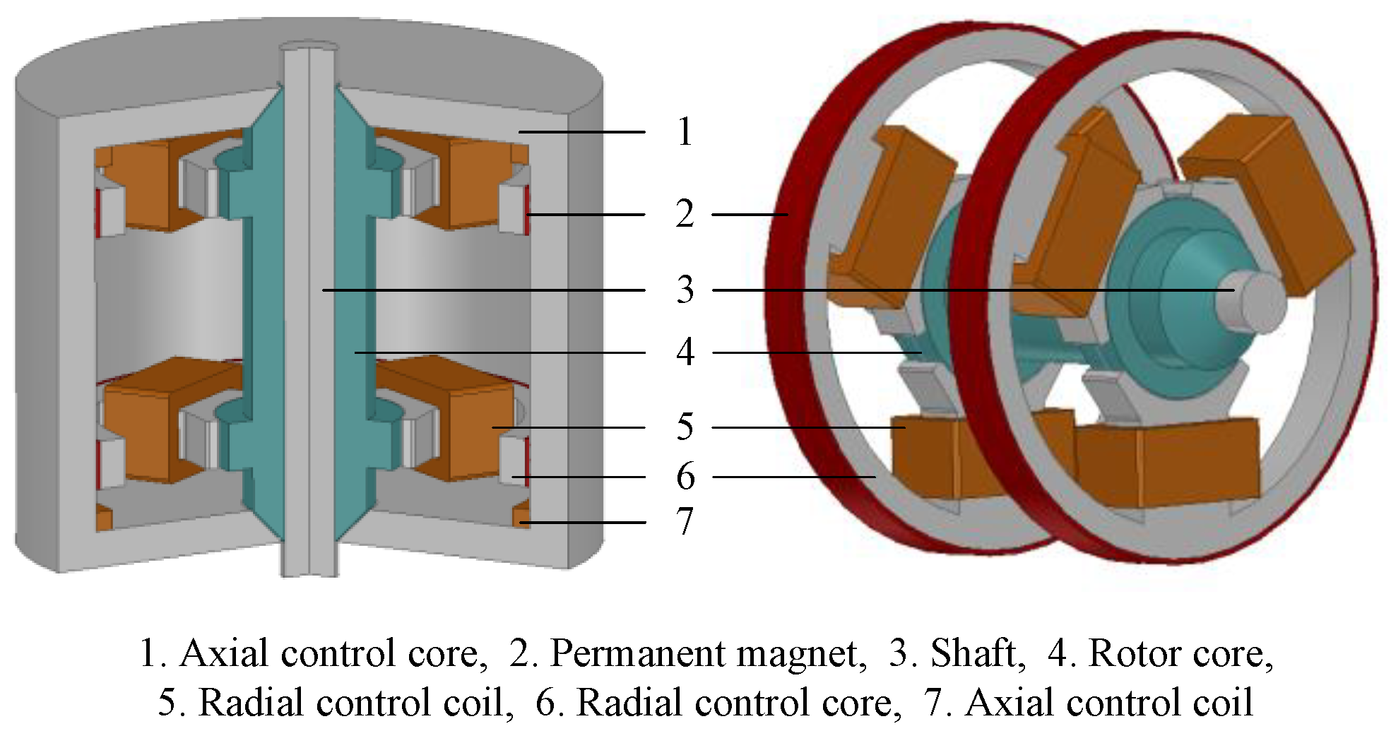
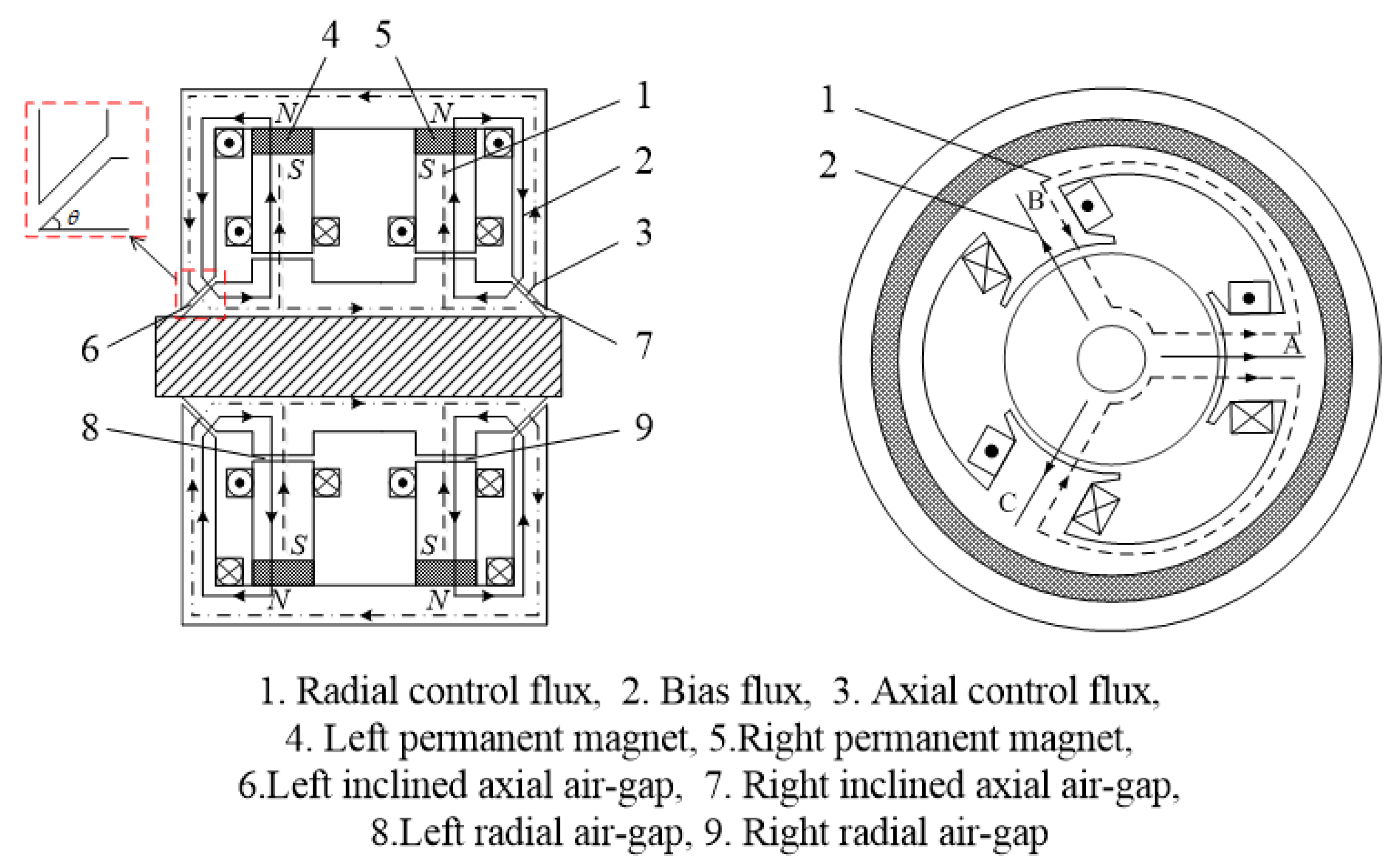
2. Structure and Working Principle

The configuration of the 5-DOF AC–DC HMB is shown in Figure 1. The HMB includes an axial control core, two axial control coils, two radial control cores, radial control coils, a rotor core, and two axially polarized permanent magnet rings. To reduce the axial length, the two ends of the rotor are designed as inclined structures. Three radial stator magnetic poles are evenly arranged around the circumference of the left and right radial control cores. Three radial control coils are, respectively, wound on the radial stator magnetic poles. For high-speed mechanical systems, high-speed electric machines can be installed between the two radial control cores and integrated with the HMB to improve the axial utilization ratio, critical speed, and power density.
Figure 2 shows the magnetic flux paths of the 5-DOF AC–DC HMB. The bias flux path (solid lines with arrows) starts from the N-pole of the permanent magnet, passing through the axial control core, axial air gap, rotor core, radial air gap, and radial control core, and finally returns to the S-pole of the permanent magnet. The axial control fluxes flow through the axial control core, the axial air gap, and the rotor core. The loop of the radial control fluxes is formed by the radial control core, the radial air gap, and the rotor core. The air-gap fluxes are composed of bias fluxes and control fluxes. Since the magnetic resistance of the permanent magnet is large, the control fluxes do not pass through the permanent magnet pole, and the demagnetization of the permanent magnet by the control fluxes can be avoided.
In the common state, the rotor is in the equilibrium position. At this moment, there is no control current, and the rotor is suspended under the magnetic attractive force generated by the bias fluxes. If the rotor is offset, the displacement sensors detect the radial and axial displacements. The axial DC power amplifier adjusts the axial control current to generate axial control fluxes, while the radial AC inverters adjust the radial control fluxes generated by the three-phase symmetrical AC current in the radial control coils. In the direction of the rotor offset, due to the superposition of the control fluxes and bias fluxes, air-gap fluxes are weakened. In the opposite direction of the rotor offset, air-gap fluxes are enhanced. The rotor is pulled back to the balanced position by the suspension forces in the opposite direction to the rotor offset direction.

3. Mathematical Model

The mathematical model is the theoretical basis of MBs. To design the 5-DOF AC–DC HMB for high-speed mechanical systems, it is necessary to derive the mathematical model of the proposed MB. This paper focuses on a novel structure and suspension principle. Therefore, the influences of flux leakage, eddy current loss, and magnetic saturation are neglected. Only the air-gap permeances are considered.

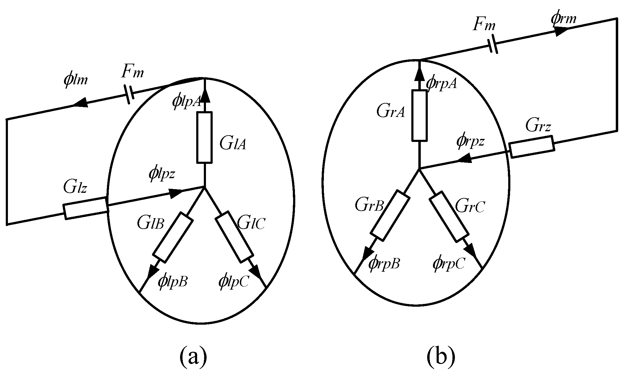
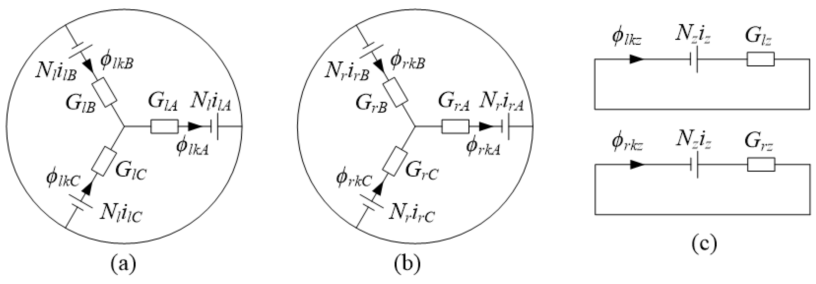
Equivalent Magnetic Circuit

Figure 3 shows an equivalent bias magnetic circuit. If the rotor is displaced in the positive X, Y, and Z directions, the magnetic permeances of each air gap can be given as
{ G l A = μ 0 S r d r x l , G r A = μ 0 S r d r x r G l B = μ 0 S r d r + 1 2 x l 3 2 y l , G r B = μ 0 S r d r + 1 2 x r 3 2 y r G l C = μ 0 S r d r + 1 2 x l + 3 2 y l , G r C = μ 0 S r d r + 1 2 x r + 3 2 y r G l z = μ 0 S a d a + z s i n θ , G r z = μ 0 S a d a z s i n θ
Due to the symmetrical structure of the left and right 2-DOF MBs, the geometric dimensions are the same.
The bias fluxes of permanent magnets at each air gap are written as
{ ϕ l p A = G l z G l z + G l A + G l B + G l C F m G l A ϕ l p B = G l z G l z + G l A + G l B + G l C F m G l B ϕ l p C = G l z G l z + G l A + G l B + G l C F m G l C
{ ϕ r p A = G r z G r z + G r A + G r B + G r C F m G r A ϕ r p B = G r z G r z + G r A + G r B + G r C F m G r B ϕ r p C = G r z G r z + G r A + G r B + G r C F m G r C
{ ϕ l p z = G l A + G l B + G l C G l z + G l A + G l B + G l C F m G l z ϕ r p z = G r A + G r B + G r C G r z + G r A + G r B + G r C F m G r z
Figure 4 shows the equivalent control magnetic circuit. The resultant fluxes at each air gap can be expressed as
{ ϕ l A = ϕ l p A + ϕ l k A = ϕ l p A + N l i l A G l A ϕ l B = ϕ l p B + ϕ l k B = ϕ l p B + N l i l B G l B ϕ l C = ϕ l p C + ϕ l k C = ϕ l p C + N l i l C G l C
{ ϕ r A = ϕ r p A + ϕ r k A = ϕ r p A + N r i r A G r A ϕ r B = ϕ r p B + ϕ r k B = ϕ r p B + N r i r B G r B ϕ r C = ϕ r p C + ϕ r k C = ϕ r p C + N r i r C G r C
{ ϕ z 1 = ϕ l k z + ϕ l p z = N z i z G l z + ϕ l p z ϕ z 2 = ϕ r k z ϕ r p z = N z i z G r z ϕ r p z
For three-phase AC systems, ilA, ilB, ilC, irA, irB, and irC meet the condition of ilA + ilB + ilC = 0 and irA + irB + irC = 0.
Therefore, the suspension force in the axial and radial directions can be written as
F z = ϕ z 1 2 ϕ z 2 2 2 μ 0 S a sin θ
{ F l A = ϕ l A 2 2 μ 0 S r F l B = ϕ l B 2 2 μ 0 S r F l C = ϕ l C 2 2 μ 0 S r
{ F r A = ϕ r A 2 2 μ 0 S r F r B = ϕ r B 2 2 μ 0 S r F r C = ϕ r C 2 2 μ 0 S r
The levitation force is nonlinear with the rotor offset and is also nonlinear with the current. The suspension force is linearized near the central position. The approximation can meet the engineering requirements. Therefore, the axial and radial suspension force can be further expressed as
F z = k f d z + k i a i z
{ F l A = F l p + k l i r i l A F l B = F l p + k l i r i l B F l C = F l p + k l i r i l C
{ F r A = F r p + k r i r i r A F r B = F r p + k r i r i r B F r C = F r p + k r i r i r C
where
{ k f d = 54 μ 0 F m 2 S r 3 S a ( S a d r + 3 S r d a ) 3 sin θ cos θ k i a = 6 μ 0 S a N z F m S r d a ( S a d r + 3 S r d a ) sin θ
{ F l p = F m 2 μ 0 S a 2 S r 2 ( S a d r + 3 S r d a ) 2 k l i r = F m μ 0 S a S r N l d r ( S a d r + 3 S r d a )
{ F r p = F m 2 μ 0 S a 2 S r 2 ( S a d r + 3 S r d a ) 2 k r i r = F m μ 0 S a S r N r d r ( S a d r + 3 S r d a )
The axial and radial suspension force can be further expressed as
{ F l x = F l A 1 2 F l B 1 2 F l C = k l i r i l A 1 2 k l i r i l B 1 2 k l i r i l C F l y = 3 2 F l B 3 2 F l C = 3 2 k l i r i l B 3 2 k l i r i l C
{ F r x = F r A 1 2 F r B 1 2 F r C = k r i r i r A 1 2 k r i r i r B 1 2 k r i r i r C F r y = 3 2 F r B 3 2 F r C = 3 2 k r i r i r B 3 2 k r i r i r C

4. Magnetic Analysis

To verify the suspension principle and mathematical models, the finite element method (FEM) was employed to calculate the electromagnetic properties of the proposed HMB, including its flux distribution, current, suspension forces, and coupling characteristics. Table 1 shows the main design parameters of the HMB.

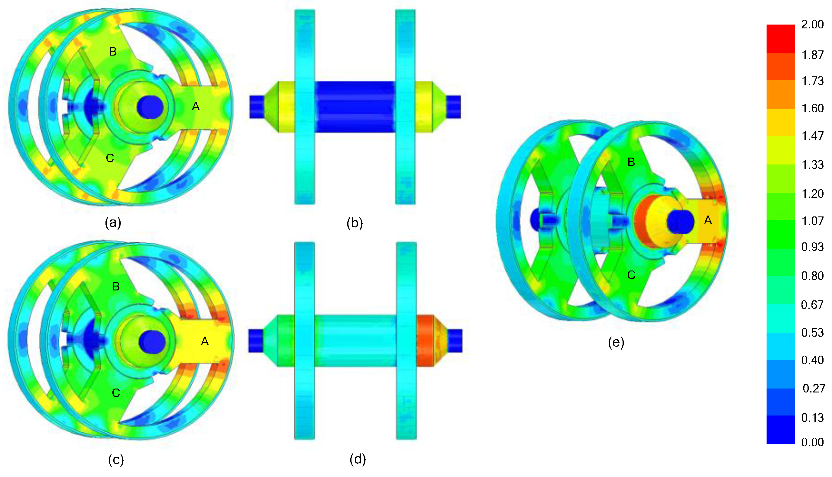
4.1. Magnetic Flux Analysis

The magnetic flux density distribution is shown in Figure 5. The radial and axial bias flux distributions of the permanent magnets are shown in Figure 5a,b, respectively. We can see from Figure 5a,b that the radial and axial bias fluxes were symmetrical, and the magnetic fields in the axial and radial air gaps were equal, so there was no resultant force on the rotor.
Assuming that the rotor moved in the −X direction, the length of the air gap in the −X direction became smaller. Therefore, the resultant forces caused the rotor to move in the −X direction further. To restore the rotor back to the central position, restoring forces in the +X direction were produced. Figure 5c shows the radial resultant fluxes. The radial control fluxes only formed a loop between the radial core and the rotor and had little effect on the bias flux distribution in the axial control core. The instantaneous fluxes at the three air gaps were different, so composite fluxes could be formed. By controlling the three-phase control currents, the fluxes were added or subtracted, and the corresponding radial restoring forces were generated to overcome the disturbance forces so that the rotor would be restored back to the central position. Therefore, the AC three-phase inverters can be used to control the radial 2-DOF and reduce the cost of the HMB system.
Similarly, if the rotor was disturbed in the Z direction, Figure 5d shows the axial resultant fluxes. It can be found that the axial fluxes were reduced at one end, while at the other end, they were increased and had little effect on the bias fluxes in the radial control core. Afterward, restoring axial forces were produced to move the rotor toward the equilibrium position.
Figure 5e shows the flux distribution when the axial control fluxes and radial control fluxes were simultaneously generated. It was further proved that the axial–radial control fluxes did not interfere with each other, and the magnetic circuit had almost no coupling.

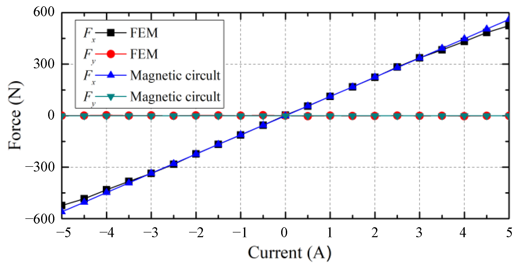
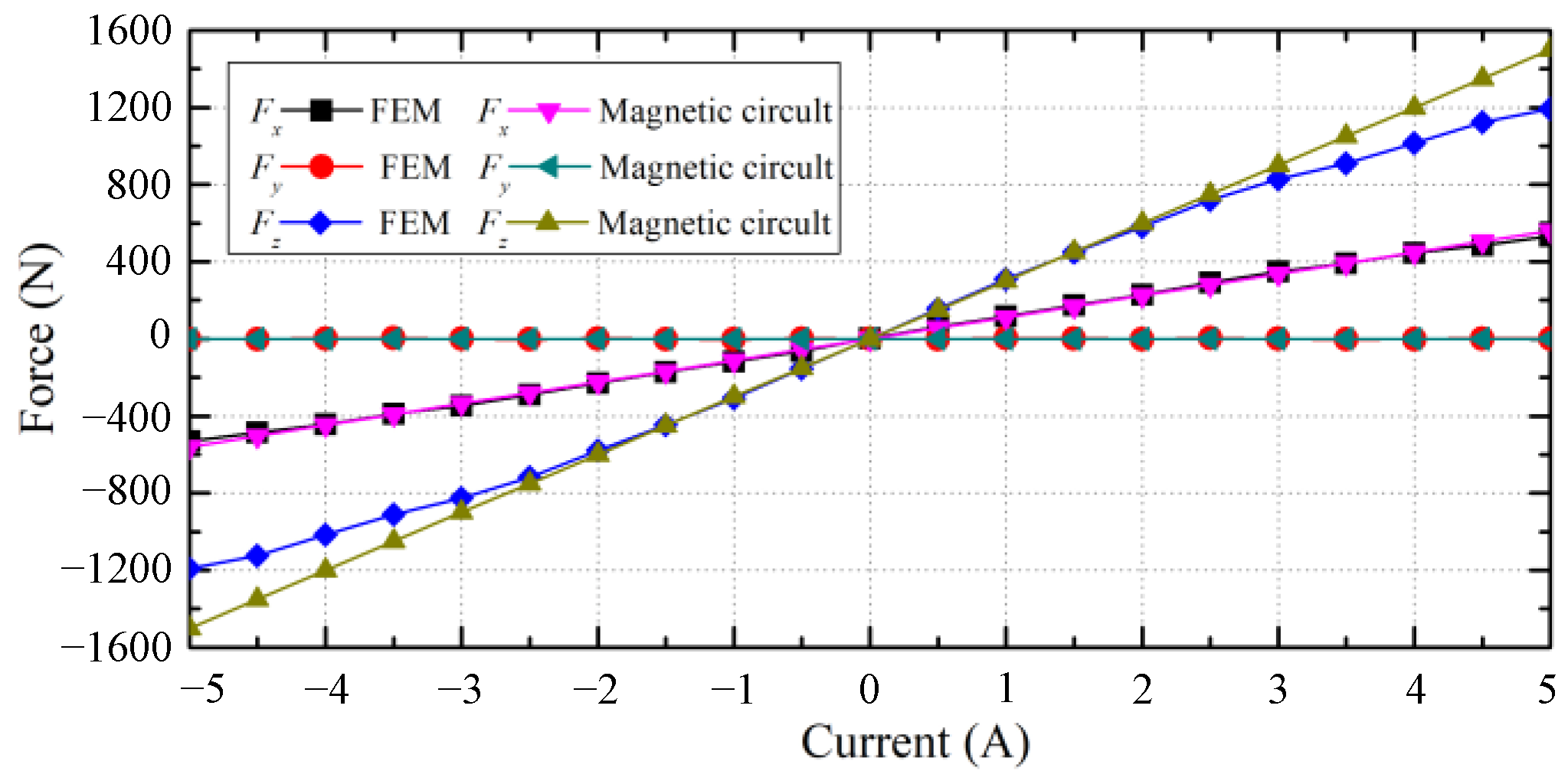
4.2. Suspension Force Analysis

For a better analysis of the relationship between current and force, three different situations were analyzed through FEM and the equivalent magnetic circuit method. First, only the radial control current was applied, and the resulting FEM simulation and equivalent magnetic circuit analysis were performed. Figure 6 shows the relationship between forces in the radial direction and the radial current at the central position of the rotor.
From the FEM results, it was found that the radial suspension force changed from −523.4 to 523.4 N with the control current changing from −5 to 5 A, and the result of the equivalent magnetic circuit indicated that the radial suspension force changed from −561.2 to 561.2 N. Thus, the results of FEM were in accordance with the results of the equivalent magnetic circuit method. It is clear that the relationship was linear between the radial force Fx and the radial current.
In the second experiment, the excitation of the axial current was only used, and the radial current was zero. The characteristics of the axial forces versus axial current at the equilibrium position of the rotor were analyzed using the FEM and equivalent magnetic circuit; the results are shown in Figure 7. Furthermore, the FEM results showed that the axial suspension force changed from −1183.6 to 1183.6 N with the axial current changing from −5 to 5 A. The calculation result of the equivalent magnetic circuit revealed that the axial suspension force changed from −1195.5 to 1195.5 N. We can see that when the axial current was small, the axial suspension force was linear with the axial current, and the FEM analysis result was consistent with the theoretical result. With the increase in the axial current, the axial force of the FEM was less than that of the equivalent magnetic circuit due to the magnetic saturation. Therefore, the linearity and consistency were ideal when working in a small current range, which can meet the actual operation requirements.
In the third experiment, under the condition of a simultaneous application of radial and axial current, Figure 8 shows the variation between the force in the radial and axial directions and the current at the central position. There are six curves in Figure 8, three of which represent Fx, Fy, and Fz calculated using FEM, and the other three represent Fx, Fy, and Fz calculated using the equivalent magnetic circuit. The results of the analysis showed that the suspension forces of the combined action of axial and radial control currents were basically the same as those of the separate action of the two control currents, which means that the radial control fluxes and axial control fluxes were basically uncoupled.
The difference between the two methods mainly results from the consideration of flux leakage, eddy current loss, and magnetic saturation. The flux leakage, eddy current loss, and magnetic saturation were considered in the FEM analysis but neglected in the equivalent magnetic circuit model. Nevertheless, the correctness of theoretical analysis was proved by a comparison of its results with those found using the FEM analysis.

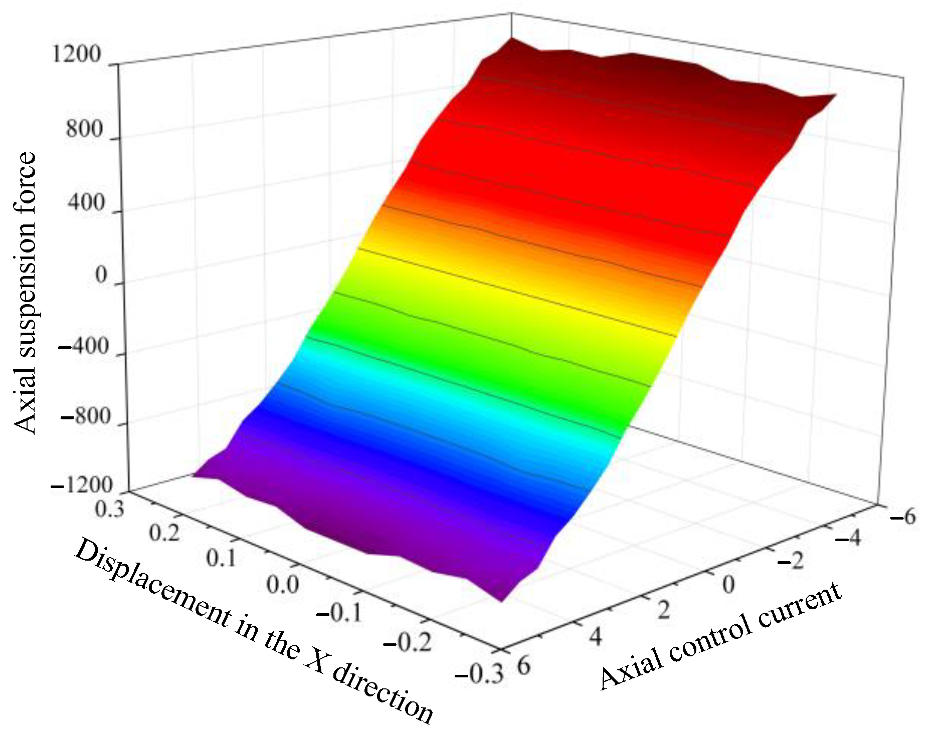
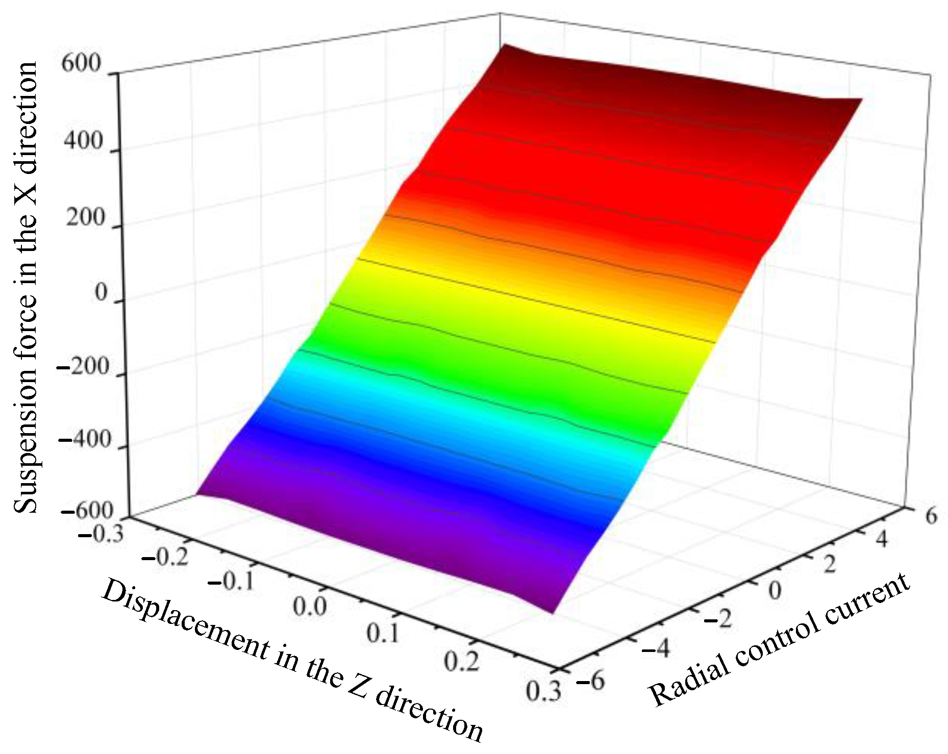
4.3. Displacement–Force–Current Analysis

Figure 9 shows the relationship between the axial suspension force and the axial control current with the rotor offset in the X direction. The rotor was in an equilibrium position in the Y and Z directions, and the control current was zero in the X and Y directions. The axial current changed from −5 to 5 A. The rotor moved from −0.25 to 0.25 mm in the X direction. When the axial current was a fixed value, the change in axial suspension force Fz was very small. This indicated that the change in the rotor displacement in the X direction had little effect on the axial suspension force Fz. Due to the magnetic saturation, the slope of the force–current curve decreased when the current was large. However, the relationship was basically linear in the effective working range of the axial control current.
Figure 10 shows the relationship between the radial suspension force in the X direction and the axial current with the rotor offset in the Z direction. The rotor was in an equilibrium position in the X and Y directions, and the control current was zero in the Y and Z directions. The radial control current in the X direction changed from −5 to 5 A. The rotor was displaced from −0.25 to 0.25 mm in the Z direction. When the radial control current in the X direction was a fixed value, we can see that the displacement in the Z direction had little effect on the force in the X direction. Although with the increase in the axial displacement, the relationship between the force in the X direction and the radial current still maintained good linearity.
Finally, from Figure 9 and Figure 10, it can be concluded that the axial control flux and the radial control flux were decoupled.

5. Conclusions

In this paper, a novel integrated AC–DC HMB was proposed, which combines two 2-DOF MBs and one single DOF MB into one unit to realize 5-DOF. Compared with the traditional 5-DOF MB, its structure is more compact, which makes the high-speed motors with this kind of MB have a higher axial utilization ratio, critical speed, and power density. The mathematical models of the 5-DOF AC–DC HMB were built to study its characteristics. The results of the comparison of 3D FEM and equivalent magnetic circuit methods in the proposed 5-DOF HMB revealed a good linear relationship between radial suspension forces versus the radial control current and between axial suspension forces versus the axial control current. The analysis of displacement–force–current indicates that there was almost no coupling between the radial control fluxes and axial control fluxes. The FEM analysis results verified the correctness of the theoretical analysis of the novel 5-DOF AC–DC HMB proposed in this study.

Author Contributions

Conceptualization, X.Y. and T.Z.; methodology, X.Y.; software, X.Y.; validation, X.Y., Y.Y., C.J. and T.Z.; formal analysis, X.Y. and Y.Y.; investigation, X.Y. and C.J.; resources, X.Y. and T.Z.; data curation, Y.Y. and C.J.; writing—original draft preparation, X.Y.; writing—review and editing, X.Y. and T.Z.; visualization, X.Y., Y.Y. and C.J.; supervision, T.Z.; project administration, X.Y. and T.Z.; funding acquisition X.Y. All authors have read and agreed to the published version of the manuscript.

Funding

This work was funded by Six Categories Talent Peak of Jiangsu Province under Grant 2019-GDZB-238.

Institutional Review Board Statement

Not applicable.

Informed Consent Statement

Not applicable.

Data Availability Statement

Not applicable.

Conflicts of Interest

The authors declare no conflict of interest.

Nomenclature

FmMagnetomotive force of the left and right permanent magnets (A)
ϕlmTotal fluxes of the left permanent magnets (Wb)
ϕrmTotal fluxes of the right permanent magnets (Wb)
GlpzLeft-inclined axial air-gap permeances (H)
GrpzRight-inclined axial air-gap permeances (H)
GlALeft radial air-gap permeances in the A direction (H)
GlBLeft radial air-gap permeances in the B direction (H)
GlCLeft radial air-gap permeances in the C direction (H)
GraRight radial air-gap permeances in the A direction (H)
GrBRight radial air-gap permeances in the B direction (H)
GrCRight radial air-gap permeances in the C direction (H)
ϕlpzLeft axial bias fluxes (Wb)
ϕrpzRight axial bias fluxes (Wb)
ϕlpALeft radial bias fluxes in the A direction (Wb)
ϕlpBLeft radial bias fluxes in the B direction (Wb)
ϕlpCLeft radial bias fluxes in the C direction (Wb)
ϕrpARight radial bias fluxes in the A direction (Wb)
ϕrpBRight radial bias fluxes in the B direction (Wb)
ϕrpCRight radial bias fluxes in the C direction (Wb)
xlLeft displacements in the X direction (m)
ylLeft displacements in the Y direction (m)
xrRight displacements in the X direction (m)
yrRight displacements in the Y direction (m)
zDisplacement in the Z direction (m)
μ0Vacuum permeability (md)
SrRadial pole face area( m2)
SaAxial pole face area (m2)
drAverage radial air gap (m)
daAxial inclined air-gap length (m)
θAngle of the inclined axial pole
ϕlkALeft radial control fluxes in the A direction (Wb)
ϕlkBLeft radial control fluxes in the B direction (Wb)
ϕlkCLeft radial control fluxes in the C direction (Wb)
ϕrkARight radial control fluxes in the A direction (Wb)
ϕrkBRight radial control fluxes in the B direction (Wb)
ϕrkCRight radial control fluxes in the C direction (Wb)
ϕlkzLeft axial control fluxes (Wb)
ϕrkzRight axial control fluxes (Wb)
NlNumbers of the left radial coil turns
NrNumbers of the right radial coil turns
ilACurrent in the A direction left radial coil (A)
ilBCurrent in the B direction left radial coil (A)
ilCCurrent in the C direction left radial coil (A)
irACurrent in the A direction right radial coil (A)
irBCurrent in the B direction right radial coil (A)
irCCurrent in the C direction right radial coil (A)
NzNumber of the axial coil turns on one side
izAxial control currents (A)
ϕlALeft radial air-gap fluxes in the A direction (Wb)
ϕlBLeft radial air-gap fluxes in the B direction (Wb)
ϕlCLeft radial air-gap fluxes in the C direction (Wb)
ϕrARight radial air-gap fluxes in the A direction (Wb)
ϕrBRight radial air-gap fluxes in the B direction (Wb)
ϕrCRight radial air-gap fluxes in the C direction (Wb)
ϕz1Left axial air-gap fluxes (Wb)
ϕz2Right axial air-gap fluxes (Wb)
FzForce in the Z direction (N)
FlALeft forces in the A direction (N)
FlBLeft forces in the B direction (N)
FlCLeft forces in the C direction (N)
FrARight forces in the A direction (N)
FrBRight forces in the B direction (N)
FrCRight forces in the C direction (N)
kfdAxial force-displacement stiffness (N/m)
kiaAxial force–current stiffness (N/m)
FlpMagnetic forces of the magnets in the left radial air gaps at the equilibrium position (N)
FrpMagnetic forces of the magnets in the right radial air gaps at the equilibrium position (N)
klirLeft radial force–current stiffness (N/m)
krirRight radial force–current stiffness (N/m)
FlxLeft resultant forces in the X directions (N)
FlyLeft resultant forces in the Y direction (N)
FrxRight resultant forces in the X direction (N)
FryRight resultant forces in the Y direction (N)
FmMagnetomotive force of the left and right permanent magnets (A)
ACAlternating current
DCDirect current
DOFDegree of freedom
MBMagnetic bearings
FEMFinite element method
HMBHybrid magnetic bearings
FEAFinite element analysis

References

  1. Sun, X.; Chen, L.; Jiang, H.; Yang, Z.; Chen, J.; Zhang, W. High-Performance Control for a Bearingless Permanent-Magnet Synchronous Motor Using Neural Network Inverse Scheme Plus Internal Model Controllers. IEEE Trans. Ind. Electron. 2016, 63, 3479–3488. [Google Scholar] [CrossRef]
  2. Noshadi, A.; Shi, J.; Lee, W.S.; Shi, P.; Kalam, A. System Identification and Robust Control of Multi-Input Multi-Output Active Magnetic Bearing Systems. IEEE Trans. Control Syst. Technol. 2015, 24, 1227–1239. [Google Scholar] [CrossRef]
  3. Sun, X.; Shi, Z.; Chen, L.; Yang, Z. Internal Model Control for a Bearingless Permanent Magnet Synchronous Motor Based on Inverse System Method. IEEE Trans. Energy Convers. 2016, 31, 1539–1548. [Google Scholar] [CrossRef]
  4. Peng, C.; Fang, J.; Xu, X. Mismatched Disturbance Rejection Control for Voltage-Controlled Active Magnetic Bearing via State-Space Disturbance Observer. IEEE Trans. Power Electron. 2014, 30, 2753–2762. [Google Scholar] [CrossRef]
  5. Sun, X.; Su, B.; Chen, L.; Yang, Z.; Xu, X.; Shi, Z. Precise control of a four degree-of-freedom permanent magnet biased active magnetic bearing system in a magnetically suspended direct-driven spindle using neural network inverse scheme. Mech. Syst. Signal Process. 2017, 88, 36–48. [Google Scholar] [CrossRef]
  6. Sun, X.; Chen, L.; Yang, Z. Overview of Bearingless Permanent-Magnet Synchronous Motors. IEEE Trans. Ind. Electron. 2012, 60, 5528–5538. [Google Scholar] [CrossRef]
  7. Zhu, W.; Zhang, T.; Le, Q.; Wang, Z. A novel five-degree-of-freedom AC-DC hybrid magnetic bearing. AIP Adv. 2020, 10, 015034. [Google Scholar] [CrossRef]
  8. Zhang, T.; Ye, X.; Mo, L.; Zhang, C.; Lu, Q.; Ding, Z.; Ni, W. Modeling and performance analysis on the five degrees of freedom slice hybrid magnetic bearing. IEEE Trans. Appl. Supercond. 2017, 29, 1–5. [Google Scholar]
  9. Zhang, W.; Zhu, H. Radial magnetic bearings: An overview. Results Phys. 2017, 7, 3756–3766. [Google Scholar] [CrossRef]
  10. Noh, M.D.; Cho, S.-R.; Kyung, J.-H.; Ro, S.-K.; Park, J.-K. Design and Implementation of a Fault-Tolerant Magnetic Bearing System for Turbo-Molecular Vacuum Pump. IEEE/ASME Trans. Mechatron. 2005, 10, 626–631. [Google Scholar] [CrossRef]
  11. Lee, J.-H.; Allaire, P.; Tao, G.; Decker, J.; Zhang, X. Experimental study of sliding mode control for a benchmark magnetic bearing system and artificial heart pump suspension. IEEE Trans. Control Syst. Technol. 2003, 11, 128–138. [Google Scholar] [CrossRef]
  12. Kosaka, R.; Nishida, M.; Maruyama, O.; Yambe, T.; Imachi, K.; Yamane, T. Effect of a bearing gap on hemolytic property in a hydrodynamically levitated centrifugal blood pump with a semi-open impeller. Bio-Medical Mater. Eng. 2013, 23, 37–47. [Google Scholar] [CrossRef] [PubMed]
  13. Sun, X.; Chen, L.; Yang, Z.; Zhu, H. Speed-Sensorless Vector Control of a Bearingless Induction Motor With Artificial Neural Network Inverse Speed Observer. IEEE/ASME Trans. Mechatron. 2012, 18, 1357–1366. [Google Scholar] [CrossRef]
  14. Jin, Z.; Sun, X.; Chen, L.; Yang, Z. Robust Multi-Objective Optimization of a 3-Pole Active Magnetic Bearing Based on Combined Curves With Climbing Algorithm. IEEE Trans. Ind. Electron. 2021, 69, 5491–5501. [Google Scholar] [CrossRef]
  15. Zhu, H.; Ju, J. Development of Three-pole Magnetic Bearings and Key Technologies. Proc. CSEE 2014, 34, 1360–1367. [Google Scholar]
  16. Zhu, H.; Zhao, Z. Decoupling Control Based on Linear/Nonlinear Active Disturbance Rejection Switching for 3-degree-of-freedom 6-pole Hybrid Magnetic Bearing. Proc. CSEE 2017, 38, 3077–3086. [Google Scholar]
  17. Le, Y.; Sun, J.; Han, B. Modeling and Design of 3-DOF Magnetic Bearing for High-Speed Motor Including Eddy-Current Effects and Leakage Effects. IEEE Trans. Ind. Electron. 2016, 63, 3656–3665. [Google Scholar] [CrossRef]
  18. Jin, Z.; Sun, X.; Cai, Y.; Zhu, J.; Lei, G.; Guo, Y. Comprehensive Sensitivity and Cross-Factor Variance Analysis-Based Multi-Objective Design Optimization of a 3-DOF Hybrid Magnetic Bearing. IEEE Trans. Magn. 2020, 57, 1–4. [Google Scholar] [CrossRef]
  19. Sun, J.; Ju, Z.; Peng, C.; Le, Y.; Ren, H. A Novel 4-DOF Hybrid Magnetic Bearing for DGMSCMG. IEEE Trans. Ind. Electron. 2016, 64, 2196–2204. [Google Scholar] [CrossRef]
  20. Sun, X.; Jin, Z.; Chen, L.; Yang, Z. Disturbance rejection based on iterative learning control with extended state observer for a four-degree-of-freedom hybrid magnetic bearing system. Mech. Syst. Signal Process. 2021, 153, 107465. [Google Scholar] [CrossRef]
  21. Tezuka, T.; Kurita, N.; Ishikawa, T. Design and Simulation of a Five Degrees of Freedom Active Control Magnetic Levitated Motor. IEEE Trans. Magn. 2013, 49, 2257–2262. [Google Scholar] [CrossRef]
  22. Xu, S.; Sun, J. A new structure for heteropolar permanent magnet biased radial magnetic bearing with subsidiary air gap. IEEE Trans. Magn. 2014, 50, 830–848. [Google Scholar] [CrossRef]
  23. Weissbacher, C.; Stelzer, H.; Hameyer, K. Application of a Tubular Linear Actuator as an Axial Magnetic Bearing. IEEE/ASME Trans. Mechatron. 2009, 15, 615–622. [Google Scholar] [CrossRef]
  24. Shi, Z.; Sun, X.; Lei, G.; Tian, X.; Guo, Y.; Zhu, J. Multiobjective Optimization of a Five-Phase Bearingless Permanent Magnet Motor Considering Winding Area. IEEE/ASME Trans. Mechatron. 2021. [Google Scholar] [CrossRef]
  25. Sun, X.; Jin, Z.; Wang, S.; Yang, Z.; Li, K.; Fan, Y.; Chen, L. Performance Improvement of Torque and Suspension Force for a Novel Five-Phase BFSPM Machine for Flywheel Energy Storage Systems. IEEE Trans. Appl. Supercond. 2019, 29, 1–5. [Google Scholar] [CrossRef]
  26. Sun, X.; Xue, Z.; Zhu, J.; Guo, Y.; Yang, Z.; Chen, L.; Chen, J. Suspension Force Modeling for a Bearingless Permanent Magnet Synchronous Motor Using Maxwell Stress Tensor Method. IEEE Trans. Appl. Supercond. 2016, 26, 1–5. [Google Scholar] [CrossRef]
  27. Sun, X.; Jin, Z.; Cai, Y.; Yang, Z.; Chen, L. Grey Wolf Optimization Algorithm Based State Feedback Control for a Bearingless Permanent Magnet Synchronous Machine. IEEE Trans. Power Electron. 2020, 35, 13631–13640. [Google Scholar] [CrossRef]
  28. Schweitzer, G. Magnetic Bearings Theory, Design, and Application to Rotating Machinery; Springer: Berlin/Heidelberg, Germany, 1989. [Google Scholar]
  29. Chen, S.; Song, M. Energy-Saving Variable Bias Current Optimization for Magnetic Bearing Using Adaptive Differential Evolution. In International Conference on Swarm Intelligence; Springer: Cham, Switzerland, 2017. [Google Scholar]
  30. Lijesh, K.P.; Hirani, H. Optimization of Eight Pole Radial Active Magnetic Bearing. J. Tribol. 2015, 137, 024502. [Google Scholar] [CrossRef]
  31. Le, Y.; Wang, K. Design and Optimization Method of Magnetic Bearing for High-Speed Motor Considering Eddy Current Effects. IEEE/ASME Trans. Mechatron. 2016, 21, 2061–2072. [Google Scholar] [CrossRef]
  32. Han, B.; Xu, Q.; Zheng, S. Integrated radial/thrust magnetic bearing without thrust disk for a high-speed driving system. IET Electr. Power Appl. 2016, 10, 276–283. [Google Scholar] [CrossRef]
  33. Hoffman, W. Behaviour and control of an inverter-fed three-pole active radial magnetic bearing. In Proceedings of the 2003 IEEE International Symposium on Industrial Electronics, Rio de Janeiro, Brazil, 9–11 June 2003; pp. 974–979. [Google Scholar]
  34. Yang, H.; Zhao, R.; Tang, Q. Study on inverter-fed three-pole active magnetic bearing. In Proceedings of the 21st Annual IEEE Applied Power Electronics Conference and Exposition, Dallas, TX, USA, 19–23 March 2006; pp. 1576–1581. [Google Scholar]
  35. Gu, H.; Zhu, H.; Hua, Y. Soft Sensing Modeling of Magnetic Suspension Rotor Displacements Based on Continuous Hidden Markov Model. IEEE Trans. Appl. Supercond. 2017, 28, 3600105. [Google Scholar] [CrossRef]
  36. Park, S.-H.; Lee, C.-W. Decoupled Control of a Disk-Type Rotor Equipped With a Three-Pole Hybrid Magnetic Bearing. IEEE/ASME Trans. Mechatron. 2009, 15, 793–804. [Google Scholar] [CrossRef]
  37. Bakay, L.; Dubois, M.; Viarouge, P.; Ruel, J. Losses in an optimized 8-pole radial AMB for Long Term Flywheel Energy Storage. In Proceedings of the 2009 International Conference on Electrical Machines and Systems (ICEMS), Tokyo, Japan, 15–18 November 2009. [Google Scholar]
  38. Hofer, M.; Schmidt, E.; Schrodl, M. Design of a three phase permanent magnet biased radial active magnetic bearing regarding a position sensorless control. In Proceedings of the 2009 Twenty-Fourth Annual IEEE Applied Power Electronics Conference and Exposition (APECE), Washington, DC, USA, 15–19 February 2009. [Google Scholar]
Figure 1. A 3D model of the 5-DOF AC–DC HMB.
Applsci 12 08931 g001
Figure 2. Flux paths of the 5-DOF AC–DC HMB.
Applsci 12 08931 g002
Figure 3. Equivalent bias magnetic circuit: (a) left bias fluxes and (b) right bias fluxes.
Applsci 12 08931 g003
Figure 4. Equivalent control magnetic circuit: (a) left radial control fluxes, (b) right radial control fluxes, and (c) axial control fluxes.
Applsci 12 08931 g004
Figure 5. Magnetic flux density diagram: (a) radial bias fluxes, (b) axial bias fluxes, (c) radial fluxes, (d) axial fluxes, and (e) resultant fluxes.
Applsci 12 08931 g005
Figure 6. The curves show the correlation between radial suspension forces and radial current.
Applsci 12 08931 g006
Figure 7. The curves show the correlation between axial suspension forces and axial current.
Applsci 12 08931 g007
Figure 8. Variations in radial and axial force with current.
Applsci 12 08931 g008
Figure 9. The influence of radial displacement on the axial suspension force–current characteristics.
Applsci 12 08931 g009
Figure 10. The influence of axial displacement on the radial suspension force–current characteristics in X direction.
Applsci 12 08931 g010
Table 1. Main design parameters.
ParametersValue
Axial stator outer diameter240 mm
Axial stator inner diameter of204 mm
Radial stator outer diameter of200 mm
Rotor diameter77.2 mm
Axial air-gap length0.7 mm
Magnet thickness2 mm
Magnet axial length20 mm
Shaft diameter12 mm
Radial air-gap length1.4 mm
Rotor length190 mm
Angle of the inclined axial pole45°
Publisher’s Note: MDPI stays neutral with regard to jurisdictional claims in published maps and institutional affiliations.

