Abstract
In order to improve the performance of motor drive systems, this paper introduces a sensorless control method for interior permanent magnet synchronous motors (IPMSM) based on the rotating high-frequency voltage injection method. The demodulation method using a synchronous frequency filter (SFF) instead of a bandpass filter (BPF) and a high pass filter (HPF) is proposed. The structure and transfer function of SFFs are introduced, and their characteristics are simulated and analyzed. Therefore, the center frequency of SFFs can be adaptively adjusted according to the estimated rotational speed, which is convenient for frequency setting. Finally, according to the proposed rotating high-frequency voltage injection method, the simulation model is built. The experimental results verify that the control strategy can maintain good position estimation accuracy, better speed tracking performance and anti-load disturbance performance.
1. Introduction
With the crises of energy shortages and environmental pollution becoming increasingly serious, electric vehicles have gradually become the research focus of automobile manufacturers because of their significant advantages of high efficiency and low emissions [1,2,3]. As one of the core components of electric vehicles, the performance of motor drive systems plays a decisive role in the performance of electric vehicles [4,5,6]. Traditionally, a rotor position sensor is required to detect the position signal to implement a motor drive system. The position sensor, such as an optical encoder, increases costs and reduces the reliability of the whole vehicle system. Hence, sensorless control technology without a rotor position sensor has become an important research focus in the motor drive field [7,8,9,10,11]. Two cases of sensorless control methods for PMSMs have been prevalent in recent years. In the range of medium and high speed, the motor model is utilized to calculate the rotor position and speed [12,13,14,15]. Some references present various methods using a disturbance observer [16], a sliding mode observer [17], a Kalman filter [18,19], and so on to estimate rotor position and speed. However, the magnitude of the back electromotive force is directly proportional to the motor speed. When the motor is operating at a low speed or a static state, the signal-to-noise ratio of the back electromotive force is too low or even zero. In the low-speed range, an external signal injection scheme is utilized to extract the rotor position information [20,21,22,23,24,25].
The high-frequency signal injection method is not dependent on the fundamental wave model of the motor. This method is based on the correspondence between the salient pole characteristics and the rotor position. The high-frequency signal is injected into the motor windings, and the high-frequency response current is detected. Then, the rotor position and speed information can be obtained by the observer [20,26]. As a popular control algorithm for zero and low-speed sensorless control, a high-frequency injection method can be divided into a high-frequency voltage injection method and a high-frequency current injection method according to the type of injection signal. According to the different reference systems and signal forms of high-frequency injections, the existing high-frequency voltage injection methods mainly include the rotating high-frequency voltage injection method in the two-phase stationary coordinate system and a pulse high-frequency injection method in the axis of the estimated two-phase rotating coordinate system. BPFs and HPFs are utilized in the signal extraction process of the traditional high-frequency signal injection method. The frequency of the motor system changes with the speed, and the cut-off frequency or the center frequency of the filters is fixed. Therefore, it is a challenge to reduce the impact of speed changes on filtering performance. In reference [20], the method of injecting two bidirectional rotating high-frequency carrier signals is utilized to improve the rotor position estimation accuracy. Four equations are constructed. In reference [26], the active disturbance rejection control strategy is used to estimate and compensate for the total disturbance of the system and improve the dynamic performance of the system. Reference [27] adopts an enhanced linear active disturbance rejection control method to compensate for the total disturbance in a feed-forward manner. Reference [28] utilizes recursive discrete Fourier transform to demodulate and collect signals, and the method can reduce the influence of a low-pass filter. Reference [29] introduces a high-frequency pulse voltage injection method, which uses a quasi-resonant controller to replace a low-pass filter to improve the dynamic performance of the system.
The main purpose of this paper is to propose a rotating high-frequency voltage injection method for IPMSM. The demodulation method, using an SFF instead of a BPF and an HPF, is utilized to extract the signal. The structure and transfer function of SFFs are introduced, and their characteristics are simulated and analyzed. It can be seen from the structure and transfer function that the center frequency of SFFs can be adaptively adjusted. Therefore, the center frequency setting is more convenient. In addition, the motor drive system can maintain good position estimation accuracy, speed tracking, and anti-load disturbance performance due to the frequency adaptive function. Finally, the simulation model of the sensorless control IPMSM system is built, and the correctness and effectiveness of the control strategy are verified using the simulation results.
2. Rotating High-Frequency Voltage Injection Method
The structure of the IPMSM sensorless control system based on a rotating high-frequency voltage injection method is shown in Figure 1 [21,22].
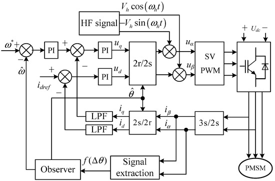
Figure 1.
IPMSM sensorless control based on rotating high-frequency voltage injection.
It can be seen from the figure that the rotor position estimation system includes three parts: the high-frequency signal injection module, the signal extraction part and the position observer. The high-frequency voltage is injected into the αβ coordinate system by the high-frequency injection module. A high-frequency response current is generated by the motor winding. The current contains rotor position information. The signal extraction part is used to extract the high-frequency response current component and separate the signal containing the rotor position information. Then, the position observer is used to obtain the estimated rotor position and speed.
The voltage equation of IPMSM in the αβ coordinate system is [28,29]
where uα and uβ are the voltage components, iα and iβ are the current components in the αβ coordinate system, L0 = (Ld + Lq)/2, L1 = (Ld − Lq)/2, Ld and Lq are the inductance in the dq coordinate system, p is the differential operator, Rs is the winding resistance and θe is the rotor position.
If the injected voltage frequency is much higher than the fundamental frequency, the resistance and the electric angular velocity in Equation (1) can be ignored. Therefore, the IPMSM equation can be approximated as a purely inductive model in the coordinate system as follows:
Equation (2) can be transformed into the current differential form as
The high-frequency voltage signal is expressed as
where Vh is the amplitude of the high-frequency voltage and ωh is the electrical angular frequency of the injected high-frequency voltage.
The high-frequency current component containing the rotor position information in the αβ coordinate system can be expressed as
where Iph and Inh are amplitudes of the high-frequency current positive and negative sequence components, respectively. Iph = Vh L0 /[ω h (L02 − L12)], Inh = −Vh L1 /[ω h(L02 − L12)].
It can be seen from the above equations that the rotor position information is contained in the current negative sequence component. To extract the rotor position information, the signal is processed according to the flow shown in Figure 2.
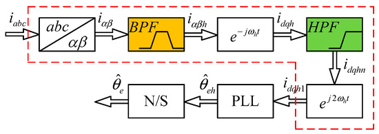
Figure 2.
Block diagram of the signal demodulation process.
- where PLL is a phase-locked loop, and N/S is the identification unit of magnetic poles N and S.
It can be seen from Figure 2 that the three-phase current of the motor is measured first. Then the three-phase current iabc is transformed to the current component iαβ in the αβ coordinate system. The high-frequency current response component iαβh can be obtained by a BPF. The synchronous coordinate transformation is used to transform iαβh into the coordinate system with a synchronous rotating frequency of ωh. The positive sequence component of the high-frequency current becomes the direct current (DC) component in this synchronous rotating coordinate system, while the negative sequence component becomes the high-frequency component rotating in −2ωh.
A synchronous rotating high-pass filter can be used to filter out the DC component and extract the negative sequence component idqhn containing rotor position information.
Using the synchronous coordinate transformation again, idqhn is transformed to a coordinate system rotating synchronously in −2ωh. The high-frequency negative sequence component containing the rotor position information then becomes a synchronously rotating DC component.
As a feedback control system for adjusting phase error, the phase-locked loop includes three parts: a phase discriminator, a voltage-controlled oscillator and a loop filter. The PLL adjusts the output phase of the system by comparing the phase error between the input signal and the output signal of the voltage-controlled oscillator so that the output phase can accurately track the input phase.
For the high-frequency injection-based PMSM sensorless control system, the equivalent phase-locked loop structure for position and speed estimation is shown in Figure 3. Here, idqh1 is used to extract the estimated rotor position and speed information.
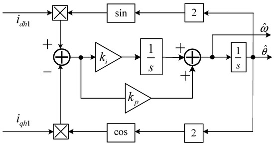
Figure 3.
Block diagram of the phase-locked loop.
The comparison unit between the actual and estimated rotor position is equivalent to the phase discriminator in the PLL. The proportional integration unit is similar to the loop filter. The primary integration unit is equivalent to the voltage-controlled oscillator part in the phase-locked loop system.
The phase discriminator module of the position and speed estimation phase-locked loop uses idh1, iqh1 and the estimated rotor position to construct a trigonometric function. The rotor position error is obtained as follows:
If the error between the estimated rotor position and the actual rotor position is small, the above equation can be further approximated as
The position error ε output by the phase discriminator is processed by a proportional integration unit to obtain the estimated rotor speed as
where GPI (s) is the expression for the proportional integral unit, s is the Laplace operator, kp is the proportionality coefficient, and ki is the integration coefficient.
The rotor position is obtained through an integral unit:
3. Proposed Signal Demodulation Method
In order to facilitate frequency parameter settings, this paper proposes a new signal demodulation method, which is shown in Figure 4. The main advantage of using an SFF to replace a BPF and an HPF in the traditional signal demodulation process is that the center frequency of an SFF can be adaptively adjusted according to the estimated rotational speed. Therefore, the frequency parameter setting is convenient while maintaining accurate rotor position estimation and good dynamic performance.
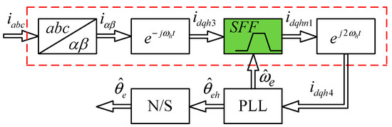
Figure 4.
Flow chart of the signal demodulation.
It can be seen from the above flow chart that the response current iabc in the ABC coordinate system can be detected. Then, the stator sampling current iabc is transformed by Clark to obtain the current iαβ in the αβ coordinate system. The current iαβ contains signal components with different frequencies and mainly includes the fundamental frequency feedback current iαβf, the high-frequency response current iαβh, and the high harmonic current iαβz due to the switching device. The other sub-harmonic components are not considered because of their small content. The current iαβ can be expressed as follows:
To extract rotor position information from high-frequency signals, the different frequency components of the signal should be separated. Transforming iαβ using synchronous coordinate transformation to a coordinate system rotated synchronously by ωh, the three components iαβf, iαβh and iαβz in the above equation become:
where ωp is the frequency of the harmonic components generated by the switching device, which is much higher than the frequency of the injection voltage.
According to Equations (14)–(16), the frequency of is obviously different from that of the other items , and . Therefore, a traditional method uses a BPF to extract the component. The upper and lower cut-off frequencies of the bandpass filter are fixed, but the frequency of the component will alter with the change in rotor speed. If the passband of the BPF is set too wide, the filtering effect will be poor. Otherwise, the useful signal will be filtered out. In order to achieve an ideal filtering effect, a BPF can be designed to change the center frequency adaptively with the speed Information. An SFF can adaptively change its center frequency with the motor speed, which can be used as a real-time variable center frequency BPF.
The SFF transfer function used in this paper is shown in Equation (17). In addition, the block diagram of its structure is given in Figure 5. It can be seen from the transfer function expression and the structure diagram that the cut-off frequency of the filter changes adaptively with the given frequency:
where x(s) and x’(s) are the input and output signals, respectively, ω′ is the center frequency of this filter, and k is the damping factor. According to the Routh criterion, it can be seen from the transfer function that the stable condition of the system is kω > 0. Therefore, as long as k is greater than 0, the system is stable.
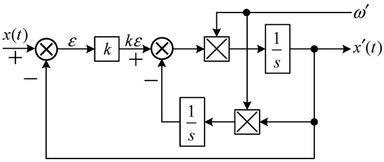
Figure 5.
Block diagram of SFF.
Rewriting Equation (17) into the form with the quality factor Q is
where A is the gain coefficient, Q = 1/k.
From Equation (18), it can be seen that only parameter k needs to be adjusted to achieve the performance adjustment of the SFF. It has obvious advantages compared with the traditional BPF. Figure 6 shows the amplitude-frequency and phase-frequency characteristic curves when the center frequency is 10 Hz, and k is taken as 0.1, 0.5 and 1, respectively. It can be seen from the figure that there are obvious attenuations at all frequencies except 10 Hz. The more the frequency is away from the center frequency, the better the filtering performance of the filter. This just meets the frequency selection requirements of the rotor position estimation system.
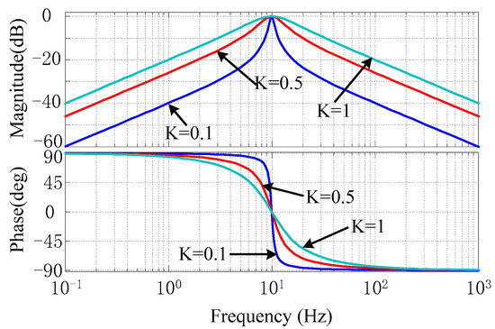
Figure 6.
Amplitude-frequency and phase-frequency characteristic curves of the SFF.
The estimated rotor speed can be used to adaptively adjust the center frequency of the SFF. The calculating formula is:
The relationship between and the estimated mechanical speed can be further expressed as follows:
From Equations (19) and (20), it can be seen that the center frequency of the SFF is influenced by the number of pole pairs, and the range of will be larger for multi-pole motors. From the phase-frequency characteristic curve, the phase margin is greater than 90 degrees. This also shows that the system is stable.
4. Verification by Simulations
In order to verify the correctness and effectiveness of the proposed method, the simulation models were built according to the IPMSM sensorless control system based on the traditional high-frequency voltage injection method and the proposed rotating high-frequency voltage injection method in the MATLAB 2014a software. It is assumed that both the motor and the operating environment are ideal. (1) The motor core is not saturated. This assumption means that there is a linear relationship between the magnetic field and winding currents. (2) The motor has a completely symmetrical magnetic circuit and winding. This assumption includes the following aspects: the three-phase windings of the stator are identical, the space positions are separated by 2/3π arc, and the excitation windings of each pole of the rotor are identical. (3) The self-inductance magnetic field of the three-phase stator winding and the mutual inductance magnetic field between the stator and the rotor winding are distributed in a sinusoidal manner along the air gap. The back EMF of the motor is a sine wave.
In the simulation models, the estimated rotor position and speed obtained by the position sensorless control system are used to replace the measured rotor position and speed, respectively. To compare the detection accuracy and dynamic performance of the sensorless algorithm, the simulation results of the two methods are shown in the following figures.
Figure 7 shows the experimental results of the traditional method from forward 50 r/min to reverse 50 r/min. Figure 7a is the given speed, which changes from forward 50 r/min to reverse 50 r/min. Figure 7b,c show the actual position and estimated position , respectively. In addition, Figure 7d presents the rotor position error. From the figure, it can be seen that the steady-state error is about 0.002 rad at 50 r/min. In the process of the speed change, the rotor position error becomes larger, and the maximum rotor position error is 0.055 rad at the moment of speed change.
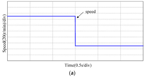
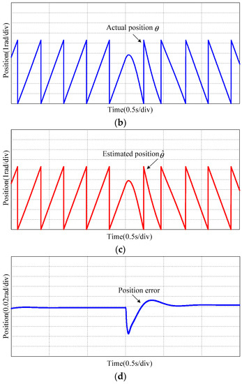
Figure 7.
Experimental results of traditional method from forward 50 r/min to reverse 50 r/min: (a) Rotor speed; (b) Actual rotor position; (c) Estimated rotor position; (d) Rotor position error.
Figure 8 shows the experimental results of the proposed method from forward 50 r/min to reverse 50 r/min. Figure 8a–c show the actual position , estimated position and the rotor position error, respectively. The experimental results show that the steady-state error is about 0.001 rad at 50 r/min, and the maximum rotor position error is 0.04 rad at the moment of speed change.
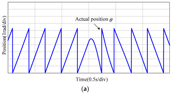
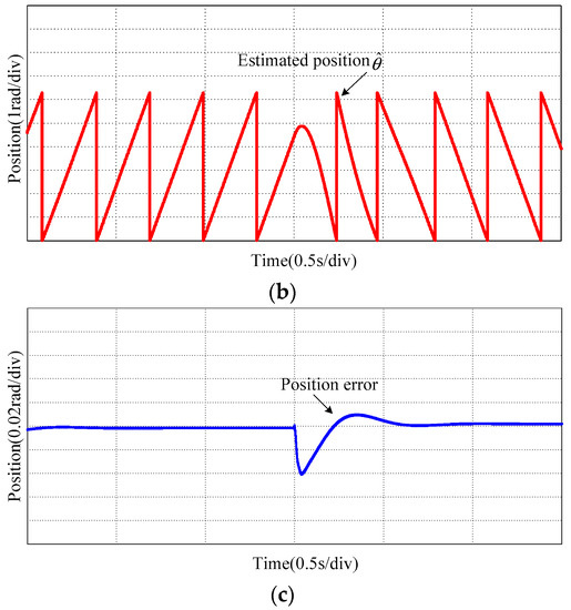
Figure 8.
Experimental results of proposed method from forward 50 r/min to reverse 50 r/min: (a) Actual rotor position; (b) Estimated rotor position; (c) Rotor position error.
The rotor position error comparison curves of the traditional method and the proposed method during the speed change are shown in Figure 9. It can be seen that the error of the proposed method is smaller than that of the traditional method. Especially when the speed changed, the error of the proposed method is 0.15 rad smaller than that of the traditional method.
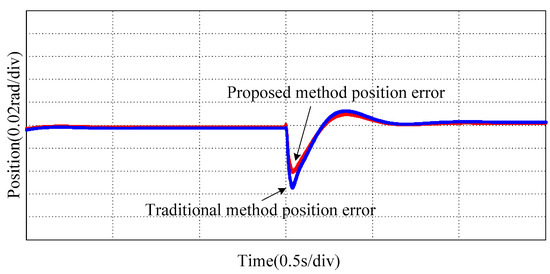
Figure 9.
Rotor position error comparison during speed change from forward 50 r/min to reverse 50 r/min.
The error comparison curves of the two methods during the load change are shown in Figure 10. Figure 10a is the given load, and Figure 10b is the rotor position error comparison curves. It can be seen that the error of the proposed method is about 0.02 rad smaller than that of the traditional method when the load changed.
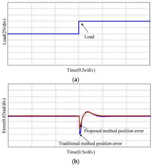
Figure 10.
Error comparison during load change: (a) Given load; (b) Rotor position error.
In addition, to analyze the system’s robustness, Figure 11 shows the error comparison curves of different resistance values. Take the winding resistance value R1 as 0.566 ohms and R2 as twice that of R1. The simulation results show that the errors of different resistance values are almost equal, no matter whether in a steady state or a dynamic state. The same results could be obtained when the motor pole pairs or inductance parameters changed. Therefore, the changes in parameters do not affect the steady-state and transient performance of the system.
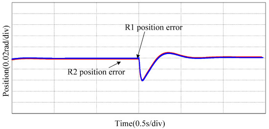
Figure 11.
The error comparison of the proposed method in different resistance parameters.
From the above simulation results, it can be seen that the rotor position error obtained by the two methods has little difference when the motor is operating in a steady state. However, the rotor position error obtained by the proposed method is obviously smaller than that obtained by the traditional method when the motor speed changes or the load changes. Therefore, the speed-tracking performance and the anti-load disturbance performance of the proposed sensorless control algorithm are better than those of the traditional method.
5. Conclusions
Based on the analysis of the traditional rotating high-frequency voltage injection method, a new signal demodulation method is proposed to realize the adaptive adjustment of frequency parameters in this paper. According to the component frequency characteristics of the stator current, an SFF is utilized to replace a BPF and an HPF, and the center frequency of the SFF is adaptively adjusted with the estimated rotation speed. The structure and transfer function of SFFs are introduced, whose characteristics are simulated and analyzed. Finally, the simulation model of a sensorless control system based on the proposed method is built, and the performance of the proposed strategy is tested. The obtained experimental results show that the control system constructed by the proposed method can maintain good position estimation accuracy, better speed tracking performance and anti-load disturbance performance.
Author Contributions
Conceptualization, Q.L.; methodology, Q.L.; software, S.G.; validation, S.G.; formal analysis, Q.L., T.Z., L.M.; writing—original draft preparation, Q.L.; writing—review and editing, S.Z. All authors have read and agreed to the published version of the manuscript.
Funding
This research was funded by the Natural Science Foundation of Jiangsu Province, grant number BK20181481, in part by the Six Categories Talent Peak of Jiangsu Province under Grant Nos. 2019-GDZB-238, in part by the Natural Science Foundation of Huai’an City under Grant Nos. HAB202062 and HAB201905, and in part by the Huai’an Key Laboratory of motion control and converter technology under Grant No. HAP201903.
Institutional Review Board Statement
Not applicable.
Informed Consent Statement
Not applicable.
Data Availability Statement
Data are contained within the article.
Conflicts of Interest
The authors declare no conflict of interest.
References
- Chen, L.; Xu, H.; Sun, X. A Novel Strategy of Control Performance Improvement for Six-Phase Permanent Magnet Synchronous Hub Motor Drives of EVs under New European Driving Cycle. IEEE Trans. Veh. Technol. 2021, 70, 5628–5637. [Google Scholar] [CrossRef]
- Fan, W.; Zhu, X.; Quan, L.; Wu, W.; Xu, L.; Liu, Y. Flux-Weakening Capability Enhancement Design and Optimization of a Controllable Leakage Flux Multilayer Barrier PM Motor. IEEE Trans. Ind. Electron. 2021, 68, 7814–7825. [Google Scholar] [CrossRef]
- Zhou, X.; Zhu, X.; Wu, W.; Xiang, Z.; Liu, Y.; Quan, L. Multi-objective Optimization Design of Variable-Saliency-Ratio PM Motor Considering Driving Cycles. IEEE Trans. Ind. Electron. 2021, 68, 6516–6526. [Google Scholar] [CrossRef]
- Korpe, U.U.; Gokdag, M.; Koc, M.; Gulbudak, O. Modulated Model Predictive Control of Permanent Magnet Synchronous Motors with Improved Steady-State Performance, 3rd ed.; Global Power Energy and Communication Conference (GPECOM): Antalya, Turkey, 2021. [Google Scholar]
- Yang, J.; Chen, W.; Li, S.; Guo, L.; Yan, Y. Disturbance/Uncertainty Estimation and Attenuation Techniques in PMSM Drives-A Survey. IEEE Trans. Ind. Electron. 2017, 64, 3273–3285. [Google Scholar] [CrossRef]
- Zhang, X.; Hou, B.; Mei, Y. Deadbeat Predictive Current Control of Permanent-Magnet Synchronous Motors with Stator Current and Disturbance Observer. IEEE Trans. Power Electron. 2017, 32, 3818–3834. [Google Scholar] [CrossRef]
- Wu, C.; Chen, Z.; Chen, Q. Hybrid-Modulation-Based Full-Speed Sensorless Control for Permanent Magnet Synchronous Motors. IEEE Trans. Power Electron. 2022, 37, 5908–5917. [Google Scholar] [CrossRef]
- Chen, G.; Chen, J.; Yang, S. Implementation issues of flux linkage estimation on permanent magnet machine position sensorless drive at low speed. IEEE Access 2019, 7, 164641–164649. [Google Scholar] [CrossRef]
- Lin, X.; Huang, W.; Jiang, W. A stator flux observer with phase self-tuning for direct torque control of permanent magnet synchronous motor. IEEE Trans. Power Electron. 2020, 35, 6140–6152. [Google Scholar] [CrossRef]
- Wu, C.; Sun, X.; Wang, J. A rotor flux observer of permanent magnet synchronous motors with adaptive flux compensation. IEEE Trans. Energy Convers. 2019, 34, 2106–2117. [Google Scholar] [CrossRef]
- Han, B.; Shi, Y.; Song, X. Initial Rotor Position Detection Method of SPMSM Based on New High Frequency Voltage Injection Method. IEEE Trans. Power Electron. 2019, 34, 3553–3562. [Google Scholar] [CrossRef]
- Liang, D.; Li, J.; Qu, R. Adaptive secondorder sliding mode observer for PMSM sensorless control considering VSI nonlinearity. IEEE Trans. Power Electron. 2018, 33, 8994–9004. [Google Scholar] [CrossRef]
- Yang, S.; Hsu, Y. Full Speed Region Sensorless Drive of Permanent-Magnet Machine Combining Saliency-Based and Back-EMF-Based Drive. IEEE Trans. Ind. Electron. 2017, 64, 1092–1101. [Google Scholar] [CrossRef]
- Lee, Y.; Sul, S.K. Model-based sensorless control of an IPMSM with enhanced robustness against load disturbances based on position and speed estimator using a speed error. IEEE Trans. Ind. Appl. 2018, 54, 1448–1459. [Google Scholar] [CrossRef]
- Zhao, K.; Yin, T.; Zhang, C. Robust Model-Free Nonsingular Terminal Sliding Mode Control for PMSM Demagnetization Fault. IEEE Access 2019, 7, 15737–15748. [Google Scholar] [CrossRef]
- Mohamed, Y.A.R.I. Design and Implementation of a Robust Current-Control Scheme for a PMSM Vector Drive with a Simple Adaptive Disturbance Observer. IEEE Trans. Ind. Electron. 2007, 54, 1981–1988. [Google Scholar] [CrossRef]
- Zhang, G. ADALINE-Network-Based PLL for Position Sensorless Interior Permanent Magnet Synchronous Motor Drives. IEEE Trans. Power Electron. 2016, 31, 1450–1460. [Google Scholar] [CrossRef]
- Aydogmus, O.; Talu, M.F. Comparison of Extended-Kalman- and Particle-Filter-Based Sensorless Speed Control. IEEE Trans. Instrum. Meas. 2012, 61, 402–410. [Google Scholar] [CrossRef]
- Myna, Z.; Vaclavek, P.; Blaha, P. Synchronous reluctance motor parameter and state estimation using extended kalman filter and current derivative measurement. IEEE Trans. Ind. Electron. 2021, 68, 1972–1981. [Google Scholar] [CrossRef]
- Tang, Q.; Shen, A.; Luo, X.; Xu, J. IPMSM Sensorless Control by Injecting Bidirectional Rotating HF Carrier Signals. IEEE Trans. Power Electron. 2018, 33, 10698–10707. [Google Scholar] [CrossRef]
- Xu, P.; Zhu, Z.Q. Analysis of parasitic effects in carrier signal injection methods for sensorless control of PM synchronous machines. IET Electr. Power Appl. 2018, 12, 203–212. [Google Scholar] [CrossRef]
- Hwang, C.E.; Lee, Y.; Sul, S.K. Analysis on Position Estimation Error in Position-Sensorless Operation of IPMSM Using Pulsating Square Wave Signal Injection. IEEE Trans. Ind. Appl. 2018, 55, 458–470. [Google Scholar] [CrossRef]
- Wang, Z.; Cao, Z.; He, Z. Improved fast method of initial rotor position estimation for interior permanent magnet synchronous motor by symmetric pulse voltage injection. IEEE Access 2020, 8, 59998–60007. [Google Scholar] [CrossRef]
- Li, M.; Huang, S.; Wu, X. A virtual HF signal injection based maximum efficiency per ampere tracking control for IPMSM drive. IEEE Trans. Power Electron. 2020, 35, 6102–6113. [Google Scholar] [CrossRef]
- Zhang, Y.; Yin, Z.; Liu, J.; Zhang, R.; Sun, X. IPMSM sensorless control using high-frequency voltage injection method with random switching frequency for audible noise improvement. IEEE Trans. Ind. Electron. 2020, 67, 6019–6030. [Google Scholar] [CrossRef]
- Zhang, G.; Wang, G.; Yuan, B. Active disturbance rejection control strategy for signal injection-based sensorless IPMSM drives. IEEE Trans. Transp. Electrif. 2018, 4, 330–339. [Google Scholar] [CrossRef]
- Wang, G. Enhanced Linear ADRC Strategy for HF Pulse Voltage Signal Injection-Based Sensorless IPMSM Drives. IEEE Trans. Power Electron. 2019, 34, 514–525. [Google Scholar] [CrossRef]
- Zhang, X.; Li, H.; Yang, S. Improved initial rotor position estimation for PMSM drives based on HF pulsating voltage signal injection. IEEE Trans. Ind. Electron. 2018, 65, 4702–4713. [Google Scholar] [CrossRef]
- Mao, Y.; Du, Y.; He, Z. Dual Quasi-Resonant Controller Position Observer Based on High Frequency Pulse Voltage Injection Method. IEEE Access 2020, 8, 213266–213276. [Google Scholar] [CrossRef]
Publisher’s Note: MDPI stays neutral with regard to jurisdictional claims in published maps and institutional affiliations. |
© 2022 by the authors. Licensee MDPI, Basel, Switzerland. This article is an open access article distributed under the terms and conditions of the Creative Commons Attribution (CC BY) license (https://creativecommons.org/licenses/by/4.0/).