Abstract
Unknown tag identification plays a pivotal role in radio frequency identification (RFID) systems, but it has not been fully investigated. This paper proposes a filter-based and parallel unknown tag identification protocol (FPUI) for open RFID systems. The FPUI adopts an RSQF-based fingerprint filter to reconcile the collision slots and discriminate the known tags from unknown tags. Meanwhile, it collects the IDs of unknown tags in parallel. FPUI achieves high performance through the following three steps: (1) adopting the RSQF-based filter to build an indicator vector, thus improving the space efficiency; (2) building a fingerprint filter to discriminate known tags from unknown tags, thus reducing the false positive rate; (3) employing a parallel identification scheme to collect the IDs of unknown tags, thus improving identification efficiency. The identification time of our protocol was minimized by conducting a theoretical analysis of the relevant parameters. Furthermore, the performance of our protocol was evaluated by conducting a wide range of simulation experiments. The theoretical analysis and simulation results indicated that our protocol significantly outperformed the current advanced protocols.
1. Introduction
Radio frequency identification (RFID) has a variety of applications in the Internet of Things, such as supply chain management [1,2,3,4,5], warehouse inventory [6,7,8,9,10], object monitoring and tracking [11,12,13,14,15], and posture recognition and localization [16,17,18,19,20]. In this broad range of RFID-enabled applications, unknown tag identification is crucial for collecting tag IDs from unexpected tags. For example, when a group of tagged objects is moved into a supermarket or warehouse such as Walmart, the manager needs to store these new tag IDs in the back-end database server for subsequent business operations such as daily inventory. In another example of a shopping mall, the customers often misplace frozen food with candy, causing the food to rot, or misplace oil near a lighter, causing great danger. The objective of unknown tag identification is to quickly identify newly added or misplaced tags from a large number of known tags. Considering a large-scale RFID system with millions of known tags whose IDs have already been stored in the back-end database previously, these known tags will participate in the identification of unknown tags, thus making it difficult to identify the unknown tags rapidly.
The existing unknown tag identification protocols are divided into two categories: probabilistic protocols [21,22,23] and deterministic protocols [24,25,26,27,28]. The probabilistic protocols can perform unknown tag detection quickly with an expected accuracy. The state-of-the-art probabilistic protocol is the collision seeking detection (CSD) protocol [23], which finds a collision seed to make many known tags collide in the last N slots with a frame size of f, thus saving the detection time and ensuring the desired detection accuracy. The deterministic protocol can correctly identify all unknown tags in a batch. Reference [25] proposed a series of protocols to improve identification performance. The basic unknown tag identification protocol (BUIP) separates known tags from unknown tags and deactivates them; the single-pairing unknown tag identification protocol (SUIP) adopts a slot pairing method, and the multi-pairing unknown tag identification protocol (MUIP) adopts multiple reselection methods to resolve the problem of known tag collisions. Meanwhile, the filtering-based unknown tag identification protocol (FUTI) and the interactive filtering-based unknown tag identification protocol (IFUTI) were investigated in [27] to separate unknown tags from known tags and assign a status code to each singleton slot, thus reducing known–unknown collisions and identifying unknown tags at the bit level. Although the existing protocols can identify unknown tags, they do not have enough time efficiency and space efficiency in open RFID systems.
This paper investigates the problem of unknown tag identification in open RFID systems and proposes a deterministic unknown tag identification protocol called the filter-based and parallel unknown tag identification (FPUI) protocol. Considering the drawbacks of the existing protocols, the proposed protocol formulates a solution that satisfies the requirements of efficiency and accuracy by: (1) taking less time and space to achieve unknown tag identification; (2) accurately collecting the information of unknown tags. To achieve these goals, the FPUI consists of two phases: the separation phase and the collection phase. In the first phase, the FPUI adopts an RSQF-based filter [29] to calculate the hash value for each known tag by and divides the hash value into two parts: and . The of tags with an identical are placed in consecutive slots from small to large, and this sequence of slots is called a . Meanwhile, the fingerprint filter assigns different fingerprints to multiple known tags in the same to reconcile the collision slots and separate the known tags from unknown tags. In the second phase, the FPUI collects the IDs of multiple tags by using a CDMA-based parallel identification method.
The main contributions of this paper are summarized as follows:
(1) A complete and robust solution to unknown tag identification in open RFID systems is provided.
(2) An RSQF-based fingerprint filter is utilized to solve the problem of slot collisions and separate the known tags from unknown tags, thus improving slot utilization and reducing the false positive rate.
(3) A parallel identification method is adopted to collect the IDs of multiple unknown tags with high efficiency.
(4) The performance of the proposed protocol is formally analyzed. The impact of various parameters on the identification time of our protocol is investigated, and the parameters are optimized to obtain the shortest identification time.
(5) Theoretical analysis and extensive simulations are conducted. The results indicate that our protocol performs better and has a lower false positive rate than the existing advanced protocols.
The rest of the paper is organized as follows. Section 2 introduces the related work. Section 3 formulates our problem. Section 4 proposes an efficient and complete unknown tag identification protocol called FPUI and theoretically analyzes its performance. Section 6 evaluates our protocol. Section 7 summarizes this paper.
2. Related Work
Many recent studies on RFID technology focus on functional applications, including information collection [30,31], cardinality estimation [32,33], tag grouping [34,35], searching a wanted tag set [36,37], and missing tag identification [38,39]. Unknown tag identification, as a research branch, is practically important because it helps identify the unknown tags that are misplaced or moved in the reader’s interrogation area. To solve this problem, two categories of protocols have been designed: the probabilistic protocol [21,22,23] and the deterministic protocol [24,25,26,27,28].
The probabilistic protocol can identify unknown tags rapidly with an expected accuracy. Liu et al. designed an unknown tag detection scheme for detecting unknown tags with an expected confidence level [21]. Gong et al. proposed the white paper (WP) protocol [22], which constructs a composite message data structure consisting of all useful informative data from some independent detection synopses. This structure helps improve the unknown tag detection efficiency and decrease the failure probability. Although these probabilistic protocols can judge unknown tags in a fast way, they cannot identify the information of all unknown tags’ IDs. Compared with the probabilistic protocol for unknown tag identification, the deterministic protocol can collect all information of unknown tags’ IDs. For example, Sheng et al. firstly formulated the problem of unknown tag identification and presented an unknown tag identification protocol called continuous scanning (CU), which can collect a specified fraction of intact unknown tags [24]. However, CU only achieves incomplete unknown tag identification caused by randomized algorithms. Liu et al. proposed the BUIP, SUIP, and MUIP protocols [25], which adopt indicator vectors to distinguish known tags from unknown tags and deactivate the known tags. Although they can identify the intact unknown tag set with higher efficiency, more time is needed. Liu et al. proposed the FUTI and IFUTI protocols [27], which investigate the interactive filters to accelerate the process of unknown tag identification. Xie et al. proposed the unknown tag identification protocol based on a coded filtering vector [26], which utilizes the coded filtering vector technique to separate unknown tags from known tags and assign each singleton slot a status code to reduce known–unknown collisions, thus improving the identification performance. Zhu et al. proposed the physical-layer unknown tag identification (PUTI) protocol [28], which identifies the unknown tags by aggregating physical layer signals. Although these deterministic protocols can identify unknown tags, they are time-consuming and suffer from a high false positive rate.
This paper proposes a filter-based and parallel unknown tag identification protocol called FPUI. The FPUI thoroughly separates known tags from unknown tags and deactivates all known tags by adopting an RSQF-based fingerprint filter, thus improving the slot utilization and the accuracy of the protocol. Meanwhile, the FPUI adopts a parallel identification method to collect multiple unknown tag IDs in parallel, thus increasing the efficiency of the protocol.
3. System Model
3.1. Assumption and Problem
This paper considered an open RFID system consisting of one reader, N known tags, M unknown tags, and some missing tags. All these tags were within the interrogating range of this reader. The IDs of all known tags (including missing tags) were already stored in the back-end database of the server, but all IDs and M unknown tags were unavailable in the server. The known tag set is denoted as , i.e., , and the unknown tag set is denoted as , i.e., . The intersection of sets and is null, i.e., . Each tag has a unique ID, and all tags are equipped with the identical hash generator . The missing tag set is a part of the known tag set . Figure 1 presents an overview of an open RFID system with unknown tags and missing tags. There are a large number of known tags and numerous unknown tags in the interrogation of the reader. Table 1 shows the notations used in this paper. The objective of our protocol is to collect the information of the intact IDs of all unknown tags from the total tag set and eliminate the influence of false positives.
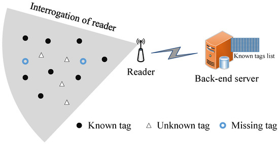
Figure 1.
The system model of unknown tag identification.

Table 1.
Notations.
3.2. Communication Slots
The physical-layer RFID communication between the reader and the tags was based on slotted ALOHA. The reader starts a slotted frame, on the basis of which each tag randomly maps itself to one of the slots by a hash function. Thus, there are three categories of slots: (1) empty slot: selected by no tags; (2) singleton slot: selected by just one tag; (3) collision slot: selected by more than one tag. In this paper, singleton slots and collision slots are also called non-empty slots. By constructing the frame and handling the statuses of slots, the reader can accumulate the functional information of the expected tags for the practical application of RFID systems.
To distinguish an empty slot from non-empty slots, the tag needs to transmit only 1 bit of information, which needs time in a slot. Meanwhile, it takes time in a slot to transmit 10 bits of information for distinguishing the three types of slots. The time for transmitting one tag ID (96 bits) from the tag to the reader is denoted by . Generally, .
4. Filter-Based and Parallel Unknown Tag Identification Protocol
In this section, the filter-based and parallel unknown tag identification (FPUI) protocol is proposed, which can identify all unknown tags within the interrogation area efficiently and completely.
4.1. Basic Idea
Most of the existing unknown tag identification protocols are based on a slotted hash, and they have two drawbacks: large time consumption and low accuracy. Firstly, the existing protocols have lower slot utilization due to slot collisions. In this case, they need multiple rounds to deactivate all known tags, which is time-consuming. Secondly, a false positive occurs when an unknown tag and a known tag pick the same slot, resulting in this unknown tag being deactivated.
The idea of the FPUI is to identify unknown tags as quickly and precisely as possible by the following three design principles:
(1) Improving slot utilization: In the slotted-ALOHA-based protocol, multiple tags may choose a slot to respond to the reader, causing slot collisions and reducing slot utilization. This protocol modifies the RSQF filter to reconcile the collision slots to single slots, thus increasing the number of useful slots.
(2) Eliminating false positives: In real open RFID systems, unknown tags may select the same slot as known tags, which causes these unknown tags to be regarded as known tags and deactivated, i.e., a false positive problem. The key to tackling the problem is separating known tags from unknown tags thoroughly. In this paper, a unique fingerprint is provided for each known tag in a to distinguish known tags from unknown tags, thus eliminating false positives.
(3) Increasing the identification efficiency: Traditional tag identification protocols adopt ALOHA-based or tree-based methods to collect the tag ID information serially, so the process is time-consuming. This paper proposes a parallel tag ID collection scheme to concurrently identify multiple unknown tags, thus increasing the identification efficiency.
To achieve the above goals, the FPUI identifies unknown tags in two phases: the separation phase and the collection phase. In the first phase, an RSQF-based fingerprint filter is built to separate known tags from unknown tags. In the second phase, the IDs of unknown tags are concurrently collected by assigning a series of orthogonal address codes to multiple singleton unknown tags, which is similar to CDMA technology.
4.2. Separation Phase
In this phase, the reader first builds an RSQF-based filter to increase the number of useful slots. Then, the reader constructs a fingerprint filter to separate known tags from unknown tags. The process of the separation phase is described in detail below.
4.2.1. Building an RSQF-Based Filter
The reader first calculates the hash value for each known tag by , where is the tag’s ID and is a random seed. The RSQF filter divides into two parts: the first q-bit part is called , denoted by , and the second r-bit part is called , denoted by . In this paper, the original RSQF filter was modified to make it adapt to our problem. The modified RSQF-based filter maintains a vector to determine whether a slot is occupied or not. A position j is occupied and is set to “1” when there is at least one tag whose . The number of “1s” in the vector up to position j is counted as , and the total number of “1s” in the vector is counted as s. Furthermore, the RSQF-based filter maintains a vector Q in which there are N slots. Each slot with a size of r bits can store a . The of tags with an identical are placed in consecutive slots from small to large. In this paper, this sequence of slots is called a , and the number of tags in a is called the . When a tag is inserted, the RSQF-based filter tries to store its in the . Here, the linear probing scheme was adopted to store the in the same . As will be described below, the RSQF-based filter seeks out an unoccupied slot to save when its is already occupied.
A slot storing a is called “used”, and a slot storing no is called “unused”. Since the RSQF-based filter uses the linear probing scheme to store , a slot may also be “used” even when its corresponding position in the vector is not occupied. The RSQF-based filter always attempts to store the in their and only drifts a when its is occupied by another . As shown in Figure 2, the RSQF-based filter maintains three vectors to determine whether a slot is “used” or not and the actual slot in which each is stored. Specifically, the bit vector with a size of is used to indicate the of each tag, the bit vector with a size of N is used to indicate the number of tags having the same , and the vector (namely Q array) is used to indicate the actual slot of each tag.

Figure 2.
A simple RSQF-based fingerprint filter.
For the convenience of expression, two operations are defined for the RSQF-based filter: and . For a given bit vector D, returns the index of the ith 1 in D, and returns the number of 1s preceding the ith position in D, i.e., . The two operations help seek out the of any . If , there is no such ; otherwise, is applied to calculate the number of slots , i.e., the number of preceding the slot , and then, is applied to calculate the end position of the th . As shown in Figure 2, the slot of tag is in the th , where . The end slot of this is , and the beginning slot of this is (we set to be ). Thus, the size of this can be obtained by . The actual slot index of tag falls between and . The tag checks the jth position in the vector (). When and , is inserted into the jth position.
4.2.2. Building Fingerprint Filter
Although the RSQF-based filter can assign a slot to each known tag, it cannot solve the slot collision problem when multiple tags have the same and . Furthermore, it cannot separate known tags from unknown tags with the same and in open RFID systems. Therefore, this paper added a vector to solve the above two problems. The reader generates a unique -bit fingerprint via a hash function for every tag in the same , where is another random seed. The reader inserts the fingerprint of each tag into the corresponding position of the vector according to the vector, as shown in Figure 2.
The reader broadcasts a request with parameters to all tags. After receiving the request, the tag firstly calculates its occupieds index by and obtains its index . Then, it obtains the beginning position and the end position in the vector. Subsequently, it calculates its fingerprint by and checks (). If , this tag regards itself as a known tag and deactivates itself. The flowchart of separation phase is shown in Figure 3. After this phase, all known tags are deactivated without participating in the collection phase.
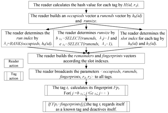
Figure 3.
The flowchart of separation phase.
4.3. Collection Phase
In this phase, our objective was to efficiently collect the IDs from all unknown tags. To save the collection time, the IDs were collected concurrently from multiple singleton unknown tags through a CDMA-based method, and each tag needs to determine its address code before transmitting its ID to the reader. The accomplishment of this goal involves four stages.
4.3.1. Building Real Frame
The real frame is constructed based on the responses of all unknown tags. In particular, the reader broadcasts a request with the parameter to issue the frame, where f is the size of the real frame and is a random seed. In this frame, each active unknown tag randomly picks a slot by the hash function f and sends a 1-bit response to the reader in this slot. The reader listens to the channel and records the status of each slot, i.e., empty and collision are recorded as “0” and singleton is recorded as “1”. Then, the reader obtains the real frame that reflects the actual responses from the unknown tags, and the frame is denoted by . is also referred to as the indicator vector, and its length is f.
For example, as shown in Figure 4, there are 10 unknown tags and . The tags are mapped to the 1st, 3nd, 6th, 5th, and 10th singleton slots, respectively, and other tags are mapped to collision slots. Therefore, the real frame (also called the indicator vector) is denoted as “1010110001”.
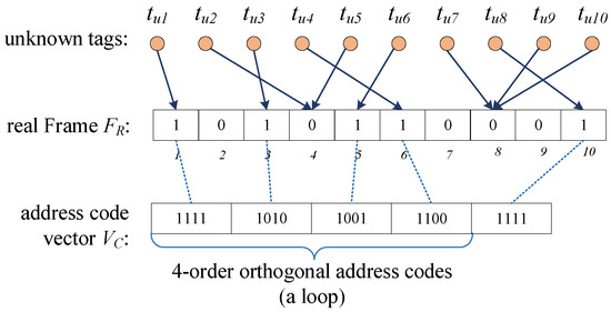
Figure 4.
Building real frame and address code vector in the collection phase.
4.3.2. Building Address Code Vector
The reader generates a series of orthogonal address codes and builds the address code vector with a length of , where is the number of “1s” in . Here, the sequence is employed to provide address codes. The sequence of order m can provide m different orthogonal address codes, and each address code is m bits long, which guarantees that m singleton unknown tags can respond in parallel. Every m singleton slot belongs to a . The address codes of all tags are different and orthogonal within a . Therefore, can be expressed as , where is the address code of the tag .
Taking Figure 4 as an example, the reader generates four orthogonal address codes and builds the address code vector .
4.3.3. Assigning Address Code
The reader broadcasts the request with parameters to all tags. Upon receiving the request, each singleton tag obtains its address code. Specifically, if the tag is mapped to the jth slot and , the address code of the tag is , where is the number of “1s” preceding the jth element in . As shown in Figure 4, after receiving and , each tag checks its index and obtains its address code. For example, the indexes of are , and the corresponding address codes are “1111”, “1010”, “1100”, “1001”, and “1111”, respectively. So far, each singleton tag has an address code, which is different and orthogonal to the address codes of other singleton tags in its .
4.3.4. Collecting IDs in Parallel
The reader broadcasts the request to issue the frame. Every m unknown tag sends its ID to the reader in the same slot. For an arbitrary unknown tag , it adopts the following encoding scheme in place of and .: (i) The tag transmits the true code of in the th slot if a bit of its ID is “1”.
(ii) The tag transmits the ones’ complement code of in the th slot if a bit of its ID is “0”.
Following the above rules, the number of real slots in the frame is . Considering the address code “1010” of , the tag traverses each binary bit of its ID. In the ID, each “0” bit in the ID is encoded by “0101”, and each “1” bit is encoded by “1010”; they are transmitted in the th slot. Upon receiving the overlapping information, the reader isolates each ID of the tag by calculating normalized inner products of each m code and the address code of this tag. If the normalized inner product is “1”, the bit received from this tag is “1”; if the normalized inner product is “−1”, the bit received from this tag is “0”; otherwise, this tag did not send information.
Take Figure 5 for example. The tags concurrently transmit their IDs in the 1st slot. The first two bits in the IDs of are . According to the rules (i) and (ii), the bits “1” and “0” are encoded by the true code and the one’ -complement code of each tag’s address code, respectively. Using “−1” to represent “0” and “+1” to represent “1”, transmits , , transmits , , transmits , , and transmits , in the first slot. Therefore, the reader receives the final overlapping information . The normalized inner product of the overlapping code and the address code determine whether a tag has sent data and what data to be sent. For example, the normalized inner product of and is “1”, which indicates that the first bit sent is “1”; the normalized inner product of and is “−1”, which indicates that the second bit sent is “0”. Consequently, the reader knows that the first two bits of ’s ID are “10”. Similarly, the reader can obtain the IDs of the other three tags.

Figure 5.
Collecting IDs in parallel.
If , the unknown tags picking this slot will participate in the next round. Then, the collection phase will be executed for several rounds until the reader cannot detect replies from unknown tags in the channel.
5. Performance Analysis
5.1. Fingerprint Size
First, the influence of fingerprint size is discussed. In our filter, each tag has a unique fingerprint in its . To achieve a higher separation accuracy, different hash functions can be chosen for each by transmitting multiple random seeds to tags. For saving the communication overhead, the fingerprint size was set to for each . To simplify the calculation, is defined as the average fingerprint size, and it is discussed below. The probability of a slot not being occupied in the vector is:
where is . The number of occupied slots in the vector is:
Therefore, the average can be calculated as:
The average fingerprint is:
5.2. Address Code Size
Next, the influence of the address code size m on the execution time is discussed. The CDMA-based scheme has high noise resistance and application adaptability. This paper chose the codes as the address codes of unknown tags, which can provide perfect orthogonal codes for concurrently identifying multiple unknown tags. However, the quality of communication may decrease when the address code size is large. Therefore, the codes with an order of 4∼64 were adopted to guarantee the communication quality, which indicates that .
According to the characteristics of the code, there are sub-carrier cycles per symbol after modulation, so the data rate is , which indicates that the data rate is in an inverse proportion to m. That is, the performance of the protocol will decrease as m increases. Letting be the time for transmitting a 96-bit ID from the tag to the reader based on the code, we have . In our protocol, .
5.3. Time Efficiency
In this section, the time efficiency of the FPUI protocol is analyzed. The execution time comprises two parts: the separation time and the collection time. The total execution time is given as:
where is the separation time and is the collection time. The separation time is represented as:
where is the time for transmitting 96-bit information from the reader to the tags, q is the size of , N is the number of known tags, and is the average length of the fingerprint. The number of bits per tag is defined as:
is minimized to obtain the optimal space efficiency. Then, the optimal parameter for minimizing is investigated. The derivative of can be given as follows:
By setting the derivatives in Equation (8) to 0, the lowest space efficiency is obtained when is . Then, the reader takes 1.93 bits to deactivate one known tag and the average fingerprint . Figure 6a shows the changes of unit execution time with respect to . Therefore, the minimum separation time is:

Figure 6.
The Optimal parameter settings for the separation time and collection time. (a) The unit space usage with respect to . (b) The unit collection time with respect to .
Then, the collection time is discussed. Considering the ith round of unknown tag IDs’ collection, the collection time, denoted by , is expressed as follows:
where , , and are the number of participating unknown tags, the frame size, and the number of singleton slots in the ith round, respectively; is the time for the tag transmitting 1 bit of information to the reader; is the time for transmitting a 96-bit ID from the tag to the reader. Note that and were based on the traditional code, and was based on the code. The probability of mapping one unknown tag to a singleton slot in this round is denoted as , which is given as follows:
where . Therefore, . This paper defines the unit collection time as the ratio of the collection time to the number of identified tags in the ith round. Therefore, we have:
Here, needs to be minimized to achieve the shortest collection time. Next, the optimal parameter is found to minimize . The derivative of is calculated as follows:
Based on the Philips I-Code system [20] and the code, we have ms, ms, ms, and ms. By setting the derivative in Equation (13) to 0, the minimum unit collection time is obtained when is . That is, the minimum execution time is taken to collect the IDs of all unknown tags when . Figure 6b shows the changes of unit execution time with respect to . As a result, the optimal collection time can be given as follows:
Substituting ms into (9), the optimal separation time can be given as follows:
5.4. Discussion on False Positive Rate
As shown in [29], the original RSQF filter takes bits to count one element, where is the load factor and is the false positive rate. When the false positive rate is smaller than 1/64, the RSQF filter has better space efficiency than other classic filters, including the Bloom filter, the Cuckoo filter, and the original QF filter. The RSQF filter maintains a load factor of up to 0.95, and our filter has the same load factor as the original RSQF filter. Meanwhile, in the RSQF filter, multiple tags in a may have the same ; in our filter, due to the tags in a having different fingerprints, our filter has a better false positive rate than the original RSQF filter.
6. Evaluation
This section evaluates the performance of our protocol and the existing CU [24], BUIP and MUIP [25], and FUTI and IFUTI protocols [27]. Also, the execution time of our protocol is compared with that of state-of-the-art unknown identification protocols.
6.1. Simulation Setting
Our protocol was implemented in Matlab and run on a ThinkPad X1 Carbon desktop computer equipped with an Intel 2.40 GHz CPU. In the simulations, there was a 302 s interval between each pair of consecutive communications from the tag to the reader and from the reader to the tags. The transmission rates in different directions were not symmetric depending on specific physical implementations and practical environments. According to the specification of the Philips I-Code system [20] and the code, we have ms, ms, ms, ms, and ms. Our simulations were executed 100 times in Matlab, and the results were averaged.
6.2. Total Execution Time
In this section, the total execution time of our protocol is analyzed and the proposed FPUI protocol is compared with some state-of-the-art protocols, including CU, BUIP and MUIP, and FUTI and IFUTI. In different applications, the number of unknown tags also varies. Therefore, in the following simulation experiments, the number N of known tags was fixed to 10,000 and the number M of unknown tags was changed in different applications. To thoroughly evaluate the performance of our protocol, two sets of simulations were conducted under two application scenarios: the scenario of low-density unknown tags and the scenario of high-density unknown tags. Furthermore, a set of simulations was conducted to evaluate the impact of the size m of the address code on the execution time.
Low-density unknown tags scenario: In this scenario, a simulation was conducted for an RFID system under low-density unknown tags. Here, the number M of unknown tags varied from 100 to 1000 with a step of 100. As shown in Figure 7a, the simulation results demonstrated that our FPUI protocol outperformed the advanced protocols in [25,27]. Specifically, the took takes 5.6 s and MUIP 18.8 s to identify 200 unknown tags, respectively. By contrast, our proposed PFUI protocol just took 0.86 s to identify 200 unknown tags, showing 84.6% and 95.4% less execution time than the IFUTI and MUIP protocols, respectively.

Figure 7.
Evaluating the execution time of different unknown identification protocols, where the number N of known tags is fixed to 10,000. (a) Low density of unknown tags. (b) High density of unknown tags.
High-density unknown tags scenario: In this scenario, a simulation was conducted for an RFID system under high-density unknown tags. Here, the number M of unknown tags varied from 5000 to 14,000 with a step of 1000. As shown in Figure 7b, the simulation results demonstrated that our FPUI protocol also performed better than the existing protocols in [25,27]. Concretely, the IFUTI protocol took 42.7 s and the MUIP protocol 107.9 s to identify 12,000 unknown tags, respectively. By contrast, our proposed FPUI protocol only took 31.9 to identify 12,000 unknown tags, showing 25.3% and 70.4% less execution time than the IFUTI and MUIP protocols, respectively.
The simulation results in Table 2 also show that our FPUI protocol was more efficient under the RFID scenario with low-density unknown tags and high-density unknown tags.
Table 2.
Total execution time of the protocols, where N is fixed to 10,000.
6.3. Impact of Address Code Variation
In this group of simulation experiments, the execution time of our protocol in an RFID system with different m values was evaluated. The size m of the address code was varied from 4 to 64 with a step of 2x. Meanwhile, The number M of unknown tags was changed from 1000 to 10,000 to observe the impact of m on the total execution time. As seen in Figure 8, the simulation results demonstrated that our FPUI protocol achieved the best performance when . This is because, as m increased, the data rate decreased and the reader needed to transmit more information to the tags for their address codes. This analysis was consistent with that presented in Section 5.2.

Figure 8.
The execution time with respect to m.
6.4. Impact of Missing Tags
Since our protocol assigns a unique fingerprint to each known tag, all known tags can be deactivated to remove false positives. Then, a set of simulations was conducted to evaluate the impact of the number n of missing tags on the deactivating accuracy. As shown in Figure 9, our protocol always deactivated all known tags regardless of the number n of missing tags, which indicates that our protocol can achieve better performance in real open RFID systems than other existing works.

Figure 9.
The deactivating accuracy with respect to n.
7. Conclusions
This paper investigated the problem of unknown tag identification in open RFID systems and proposed a filter-based parallel unknown tag identification protocol (FPUI), which can address the unknown tag identification problem completely and efficiently. FPUI first separates known tags from unknown tags by constructing an RSQF-based fingerprint filter, deactivating all known tags and eliminating false positives. Then, it effectively identifies unknown tags by using a CDMA-based parallel identification scheme. A theoretical analysis was conducted to optimize the parameters for minimizing the total execution time. Meanwhile, many simulation experiments were carried out to evaluate the performance of the proposed protocol. The simulation results indicated that the proposed protocol comparatively outperformed the existing advanced protocols.
Author Contributions
Investigation, H.L. and J.L.; Methodology, R.G. and C.H.; Project administration, X.T., S.S. and J.L.; Writing—original draft, X.W. All authors have read and agreed to the published version of the manuscript.
Funding
This research was financially supported by the National Natural Science Foundation of China (Nos. 61702257, 61272418), the Open Foundation of State Key Laboratory for Novel Software Technology for Nanjing University (No. KFKT2021B15), the Jinling Institute of Technology High Level Talents Research Foundation (No. jit-b-202118), and the Major Project of Natural Science Foundation of the Jiangsu Higher Education Institutions of China (No. 18KJA520003, 21KJA120001).
Institutional Review Board Statement
Not applicable.
Informed Consent Statement
Not applicable.
Data Availability Statement
Not applicable.
Conflicts of Interest
The funders had no role in the design of the study; in the collection, analyses, or interpretation of data; in the writing of the manuscript; or in the decision to publish the results.
References
- Liu, X.; Yin, J.; Zhang, S.; Xiao, B.; Ou, B. Time-Efficient Target Tags Information Collection in Large-Scale RFID Systems. IEEE Trans. Mob. Comput. 2020, 20, 2891–2905. [Google Scholar] [CrossRef]
- Gaukler, G.M. Item-Level RFID in a Retail Supply Chain with Stock-Out-Based Substitution. IEEE Trans. Ind. Inform. 2011, 7, 362–370. [Google Scholar] [CrossRef]
- Choi, T.M. Coordination and Risk Analysis of VMI Supply Chains with RFID Technology. IEEE Trans. Ind. Inform. 2011, 7, 497–504. [Google Scholar] [CrossRef]
- Xiao, Q.; Zhang, Y.; Chen, S.; Chen, M.; Liu, J. Estimating Cardinality of Arbitrary Expression of Multiple Tag Sets in a Distributed RFID System. IEEE/ACM Trans. Netw. 2019, 27, 748–762. [Google Scholar] [CrossRef]
- Yu, J.; Zhang, P.; Chen, L.; Liu, J.; Zhang, R.; Wang, K.; An, J. Stabilizing Frame Slotted Aloha Based IoT Systems: A Geometric Ergodicity Perspective. IEEE J. Sel. Areas Commun. 2021, 39, 714–725. [Google Scholar] [CrossRef]
- Fyhn, K.; Jacobsen, R.M.; Popovski, P.; Larsen, T. Fast Capture-Recapture Approach for Mitigating the Problem of Missing RFID Tags. IEEE Trans. Mob. Comput. 2012, 11, 518–528. [Google Scholar] [CrossRef]
- Simon, M.; Divsalar, D. Some interesting observations for certain line codes with application to RFID. IEEE Trans. Commun. 2006, 54, 583–586. [Google Scholar] [CrossRef]
- Yang, L.; Lin, Q.; Duan, C.; An, Z. Analog On-Tag Hashing: Towards Selective Reading as Hash Primitives in Gen2 RFID Systems. In Proceedings of the ACM MobiCom, Snowbird, UT, USA, 16–20 October 2017; pp. 301–314. [Google Scholar]
- Yu, J.; Liu, J.; Zhang, R.; Chen, L.; Gong, W.; Zhang, S. Multi-Seed Group Labeling in RFID Systems. IEEE Trans. Mob. Comput. 2020, 19, 2850–2862. [Google Scholar] [CrossRef]
- Shahzad, M.; Liu, A.X. Probabilistic Optimal Tree Hopping for RFID Identification. IEEE/ACM Trans. Netw. 2015, 23, 796–809. [Google Scholar] [CrossRef]
- Ding, H.; Qian, C.; Han, J.; Xiao, J.; Zhang, X.; Wang, G.; Xi, W.; Zhao, J. Close-proximity Detection for Hand Approaching using Backscatter Communication. IEEE Trans. Mob. Comput. 2019, 18, 2285–2297. [Google Scholar] [CrossRef]
- Shangguan, L.; Zhouy, Z.; Zheng, X.; Yang, L.; Liu, Y.; Han, J. ShopMiner: Mining Customer Shopping Behavior in Physical Clothing Stores with COTS RFID Devices. In Proceedings of the ACM SenSys, Seoul, Korea, 1–4 November 2015; pp. 113–126. [Google Scholar]
- Choi, J.; Lee, I.; Du, D.Z.; Lee, W. FTTP: A Fast Tree Traversal Protocol for Efficient Tag Identification in RFID Networks. IEEE Commun. Lett. 2010, 14, 713–715. [Google Scholar] [CrossRef]
- Shi, X.; Cai, H.; Wang, M.; Wang, G.; Huang, B.; Xie, J.; Qian, C. TagAttention: Mobile Object Tracing with Zero Appearance Knowledge by Vision-RFID Fusion. IEEE/ACM Trans. Netw. 2021, 29, 890–903. [Google Scholar] [CrossRef]
- Motroni, A.; Buffi, A.; Nepa, P.; Tellini, B. Sensor-Fusion and Tracking Method for Indoor Vehicles with Low-Density UHF-RFID Tags. IEEE Trans. Instrum. Meas. 2020, 70, 1–14. [Google Scholar] [CrossRef]
- Yang, L.; Chen, Y.; Li, X.Y.; Xiao, C.; Li, M.; Liu, Y. Tagoram: Real-Time tracking of mobile RFID tags to high precision using COTS devices. In Proceedings of the ACM MobiCom, Maui, HI, USA, 7–11 September 2014; pp. 237–248. [Google Scholar]
- Benes, F.; Stasa, P.; Svub, J.; Alfian, G.; Kang, Y.-S.; Rhee, J.-T. Investigation of UHF Signal Strength Propagation at Warehouse Management Applications Based on Drones and RFID Technology Utilization. Appl. Sci. 2022, 12, 1277. [Google Scholar] [CrossRef]
- Liu, J.; Chen, X.; Chen, S.; Liu, X.; Wang, Y.; Chen, L. TagSheet: Sleeping Posture Recognition with Unobtrusive Passive Tag Matrix. In Proceedings of the IEEE INFOCOM, Paris, France, 29 April–2 May 2019; pp. 874–882. [Google Scholar]
- Stefaniak, P.; Jachnik, B.; Koperska, W.; Skoczylas, A. Localization of LHD Machines in Underground Conditions Using IMU Sensors and DTW Algorithm. Appl. Sci. 2021, 11, 6751. [Google Scholar] [CrossRef]
- Liu, J.; Chen, S.; Chen, M.; Xiao, Q.; Chen, L. Pose Sensing with a Single RFID Tag. IEEE/ACM Trans. Netw. 2020, 28, 2023–2036. [Google Scholar] [CrossRef]
- Liu, X.; Qi, H.; Li, K.; Stojmenovic, I.; Liu, A.X.; Shen, Y.; Qu, W.; Xue, W. Sampling Bloom Filter-Based Detection of Unknown RFID Tags. IEEE Trans. Commun. 2015, 63, 1432–1442. [Google Scholar] [CrossRef]
- Gong, W.; Liu, J.; Yang, Z. Efficient Unknown Tag Detection in Large-Scale RFID Systems with Unreliable Channels. IEEE/ACM Trans. Netw. 2017, 25, 2528–2539. [Google Scholar] [CrossRef]
- Liu, X.; Chen, S.; Liu, J.; Qu, W.; Xiao, F. Fast and Accurate Detection of Unknown Tags for RFID Systems? Hash Collisions are Desirable. IEEE/ACM Trans. Netw. 2020, 28, 126–139. [Google Scholar] [CrossRef]
- Sheng, B.; Li, Q.; Mao, W. Efficient continuous scanning in RFID systems. In Proceedings of the IEEE INFOCOM, San Diego, CA, USA, 14–19 March 2010; pp. 1–9. [Google Scholar]
- Liu, X.; Xiao, B.; Zhang, S.; Bu, K. Unknown Tag Identification in Large RFID Systems: An Efficient and Complete Solution. IEEE Trans. Parallel Distrib. Syst. 2015, 26, 1775–1788. [Google Scholar] [CrossRef]
- Xie, X.; Li, K.; Liu, X. An Unknown Tag Identification Protocol Based on Coded Filtering Vector in Large Scale RFID Systems. In Proceedings of the IEEE ICCCN, Shanghai, China, 4–7 August 2014; pp. 1–9. [Google Scholar]
- Liu, X.; Li, K.; Min, G.; Lin, K.; Xiao, B.; Shen, Y.; Qu, W. Efficient Unknown Tag Identification Protocols in Large-Scale RFID Systems. IEEE Trans. Parallel Distrib. Syst. 2014, 25, 3145–3155. [Google Scholar] [CrossRef]
- Zhu, F.; Xiao, B.; Liu, J.; Chen, L. Efficient Physical-Layer Unknown Tag Identification in Large-scale RFID Systems. IEEE Trans. Commun. 2017, 65, 283–295. [Google Scholar] [CrossRef]
- Pandey, P.; Bender, M.A.; Johnson, R.; Patro, R. A General-Purpose Counting Filter: Making Every Bit Count. In Proceedings of the ACM SIGMOD 2017, Chicago, IL, USA, 14–19 May 2017; pp. 775–787. [Google Scholar]
- Buffi, A.; Michel, A.; Nepa, P.; Tellini, B. RSSI Measurements for RFID Tag Classification in Smart Storage Systems. IEEE Trans. Instrum. Meas. 2018, 67, 894–904. [Google Scholar] [CrossRef]
- Liu, J.; Chen, S.; Xiao, Q.; Chen, M.; Xiao, B.; Chen, L. Efficient Information Sampling in Multi-Category RFID Systems. IEEE/ACM Trans. Netw. 2019, 27, 159–172. [Google Scholar] [CrossRef]
- Arjona, L.; Landaluce, H.; Perallos, A.; Onieva, E. Scalable RFID Tag Estimator with Enhanced Accuracy and Low Estimation Time. IEEE Signal Process. Lett. 2017, 24, 982–986. [Google Scholar] [CrossRef]
- Liu, X.; Li, K.; Liu, A.X.; Guo, S.; Shahzad, M.; Wang, A.L.; Wu, J. Multi-Category RFID Estimation. IEEE/ACM Trans. Netw. 2017, 25, 264–277. [Google Scholar] [CrossRef]
- Liu, J.; Chen, M.; Xiao, B.; IEEE, F.Z.; Chen, S.; Chen, L. Efficient RFID Grouping Protocols. IEEE/ACM Trans. Netw. 2016, 24, 3177–3190. [Google Scholar] [CrossRef]
- Wang, X.; Liu, J.; Wang, Y.; Chen, X.; Chen, L. Efficient Tag Grouping via Collision Reconciliation and Data Compression. IEEE Trans. Mob. Comput. 2020, 20, 1817–1831. [Google Scholar] [CrossRef]
- Vizziello, A.; Savazzi, P. Efficient RFID Tag Identification Exploiting Hybrid UHF-UWB Tags and Compressive Sensing. IEEE Sens. J. 2016, 16, 4932–4939. [Google Scholar] [CrossRef]
- Chen, M.; Luo, W.; Mo, Z.; Chen, S.; Fang, Y. An Efficient Tag Search Protocol in Large-Scale RFID Systems with Noisy Channel. IEEE/ACM Trans. Netw. 2016, 24, 703–716. [Google Scholar] [CrossRef]
- Wang, X.; Liu, J.; Wang, Y.; Chen, X.; Chen, L. Efficient missing tag identification in blocker-enabled RFID systems. Comput. Netw. 2019, 164, 106894. [Google Scholar] [CrossRef]
- Su, J.; Sheng, Z.; Liu, A.X.; Fu, Z.; Huang, C. An efficient missing tag identification approach in RFID collisions. IEEE Trans. Mob. Comput. 2021. [Google Scholar] [CrossRef]
Publisher’s Note: MDPI stays neutral with regard to jurisdictional claims in published maps and institutional affiliations. |
© 2022 by the authors. Licensee MDPI, Basel, Switzerland. This article is an open access article distributed under the terms and conditions of the Creative Commons Attribution (CC BY) license (https://creativecommons.org/licenses/by/4.0/).