Abstract
Nowadays, one of the most promising areas in the motor industry is the production of BLDC motors, which are used in a wide range of applications and products—from power tools to electrical vehicles. The windings of BLDC motors are connected according to the Delta or Star circuits. However, such circuits (Delta or Star) do not allow dynamically changing the parameters of the BLDC motor during operation and thus reducing the overall motor efficiency. This paper deals with and proposes an electronic switch of the BLDC motor windings, which brings an advantage in having a capability of dynamically switching the windings during operation and thus increasing the efficiency of the BLDC motor performance.
1. Introduction
BLDC motors have become popular in a wide variety of fields, including power tools, electrical vehicles, and UAVs. They are characterized by a high dynamic response, high specific power, and compact design [1,2,3,4,5,6]. The basic configuration of the BLDC motor can be seen in Figure 1 (left), which serves as an animation of such a motor with 12 poles divided into three phases (highlighted in red, blue, and green), and 16 rotor magnets. In Figure 1 (right) one can see a demonstrator of this BLDC motor. Changing the characteristics of a real BLDC motor can be done by varying its physical dimensions, the number of stator poles, or the number of rotor magnets. Changing the BLDC motor performance characteristics are not done on demand under the operation, in most cases, for dynamic changes there can only be used different configurations of the BLDC windings [7,8]. Since the BLDC motors have many windings connected in series in phases A, B, and C [9,10,11,12], it is possible to change the stator windings according to not only the Star or Delta schemes among these three phases but also to connect individual windings inside the phase itself according to different schemes [13,14,15]. Thus, it is possible to change the characteristics of the BLDC motor in a wide range to obtain maximal efficiency, even though most existing BLDC motors have a fixed connection scheme of stator windings, i.e., in the Star or Delta configuration. Occasionally, there are relay automata that switch these circuits between each other to facilitate the start of the BLDC motor at its initial acceleration stage.
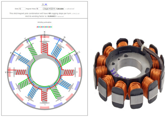
Figure 1.
The BLDC motor animation with 12 poles, 16 rotor magnets.
Unlikely, this paper presents a solution which comes up with the possibility to dynamically change the performance characteristics on demand during the whole operation. The contribution of the solution lies in using an electronic switch of stator windings, which allows for expanding the dynamic range of the BLDC motor’s speed under its operation, which is in contrast to current solutions with the fixed Star/Delta winding schemes. To quickly change the configuration of the windings during the operation of the BLDC motor, using an electronic winding switch is proposed. The electronic winding switch, in accordance with the specified load characteristic of the asynchronous DC motor or by an external signal, switches the winding circuits to obtain maximum efficiency, torque or speed [16,17,18,19]. When working with multi-pole and high-speed motors (at high PWM frequencies), the imperfections of the electromechanical system should be taken into account [20].
As internal power switching elements, there are utilized pairs of unipolar FET transistors connected in anti-series to eliminate the influence of internal protective diodes. This solution makes it possible to rebuild the production of BLDC motors to a completely new product line with minimal costs leading to BLDC motors capable of wide operational ranges and still being more economical, reliable, and efficient without failures.
To test and demonstrate the benefits of the proposed BLDC motor solution with the electronic winding switch, the BLDC motor with 16 magnets in the rotor and a stator winding circuit ABCABCABCABC was chosen. All windings have the same direction, the end of the first winding is connected to the beginning of the following one, etc. Each phase of this BLDC motor has four poles connected in series. With such a connection, it is possible obtain a connection diagram of the Star type, as shown in Figure 2. A standard 12-pole BLDC motor can have up to six different dynamic circuits of the winding configuration if the Delta and Star scheme are considered. An electronic switch can be used to commutate the windings during motor operation [21], which is taken in the proposed approach as an advantage.
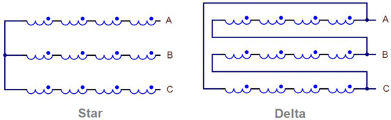
Figure 2.
Diagram connection pole phase.
Four-phase windings can be switched according to three different schemes (the total relative phase resistance is indicated next to Figure 3).
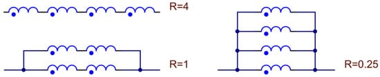
Figure 3.
Possible connection schemes for four poles.
By changing the switching circuit of the windings, different energy characteristics is obtained due to the changes in the inductance and current strength. The relationship of these values is given by the formula:
where W represents a magnetic field energy, L stands for the total inductance of the phase windings, and I is an operating current of the phase windings.
2. Realization of the Electronic Switch with a Modified BLDC Motor
For the experiment, a standard GBM5208 12-pole BLDC motor was used in which all the stator windings were disconnected and a separate output was made for each of them in the form of a thin wire with fluoroplastic insulation while maintaining numbering and polarity. The original BLDC motor and its modified variant are depicted in Figure 4.
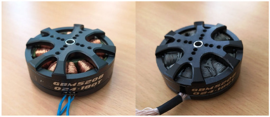
Figure 4.
Original and modified motors GBM5208—original (left) and modified (right).
The complete circuit of the electronic switch used to switch the winding schemes of the 12-pole BLDC motor contains 3 × 9 switching elements, see Figure 5.
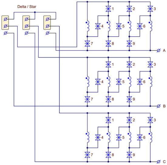
Figure 5.
General scheme of the electronic switch windings.
For the purpose of switching among winding schemes jumpers have been used. These commutation elements do switch the 12-stator windings among each other to obtain six working circuits with different parameters, shown in Figure 6. The higher the inductance of the switched scheme, the higher the torque of the BLDC motor and the lower its speed. Each connection scheme of the stator windings has its own dynamic range, effective operating speed, and current consumption.
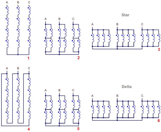
Figure 6.
Six possible winding switching schemes.
Switching during the operation of the BLDC motor of various winding connection schemes is similar to an automatic transmission in a car when the transmission stages are switched depending on the required dynamic characteristics of the ride. Such a switch can also be made by a control signal from the operator, which is similar to manual transmission in a car. Since all three phases must be switched simultaneously, for switching all 27 switching elements, there have been used 9 control signals that come from a diode matrix, where the signal of switching a particular circuit of the windings (IN1-IN3) is divided into separate switching elements S1–S9, see Figure 7.
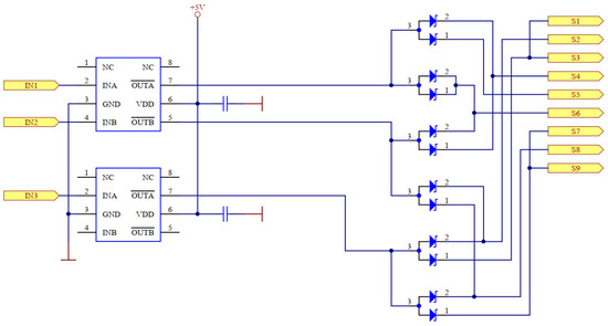
Figure 7.
Separation of the control signals by a diode matrix.
Since the windings in the BLDC motor work in AC mode, each pair of unipolar transistors with counter-switching is selected as a power switching element to eliminate the influence of an internal security diode. The electronic circuit of the power switching element is depicted in Figure 8.
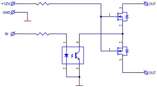
Figure 8.
Power switching element.
These transistors have a very low internal resistance, which minimizes large heat losses during the operation of the switch with a high-current load. According to scheme in Figure 8, an electronic switch of the BLDC motor windings has been developed and manufactured. The modified BLDC motor is connected to the electronic switch with the preservation of the winding numbering, as seen in Figure 9.
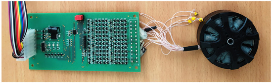
Figure 9.
The realization of the electronic switch.
To compare the characteristics of a standard BLDC motor with the modified one controlled by an electronic switch, a test bench was assembled. The assembly is shown in Figure 10.
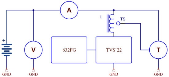
Figure 10.
The experimental set-up.
The test set-up consisted of: 24-Volt power supply, voltmeter (V), amperemeter (A), BLDC motor (M), ESC controller for BLDC motor rotation (ESC), tachometer (RPM) for measuring the speed of rotation, and the electronic switch of the stator windings (ESW) for operational commutation of the winding connection circuits.
3. Experimental Verification and Results
Winding connection options 1–3 are connected according to the Star scheme, and winding connection options 4–6 are connected according to the Delta scheme; for details see Figure 6. All measurements were made at a constant supply voltage of +24 Volts. The results are summarized in Table 1.

Table 1.
Dependency of RPM on the stator windings configuration and operating current.
The main results confirmed that the Star windings connection scheme and the switching scheme inside the phase with its maximal resistance reaches its optimal performance for the low speed (high traction loads). In contrast, the Delta circuit and the switching circuit inside the phase with its minimal resistance are more efficient under the high speed conditions. The performances labeled by scheme numbers from Table 1 are further depicted in Figure 11. The progressions show that each connection option of the stator windings has its optimal range of operating speeds, which is indicated with a bar chart at the bottom of the graph. The color indicates an optimal winding scheme selected. The progressions fully confirm the theoretical justification and confirm that the electronic switch did not affect the performance itself but enabled dynamic winding switching capability even under the operation without any negative effect on the performance.
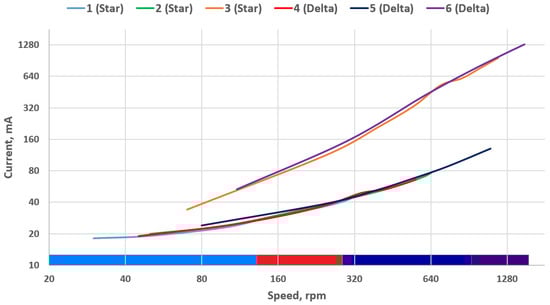
Figure 11.
Dependency of RPM on the connection of the stator windings and operating current.
With respect to results shown in Figure 11, to obtain stable operation and high torque on the shaft no matter the operational conditions and demands, it is recommended to connect the windings according to option No. 1 for the stable low speed conditions and high torque. Unlikely, to obtain maximum speed with an optimal performance it is recommended to set the connection scheme according to the option No. 6. The “dip” is clearly visible on the operating current progression for options No. 3 and No. 6. This is due to the small values of the winding impedance of the motor developed for the testing. This disadvantage can be further eliminated at the stage of calculating the characteristics of a BLDC motor designed to work with a winding switch.
Since the speed of the BLDC motor is directly related to the KV coefficient, it is clear that when switching windings within different schemes, the KV coefficient also changes. The KV coefficient has a direct effect on the reliability of rotation synchronization when controlling back electro-magnetic force (BEMF) signals. When switched schemes 1 and 2 are compared under the same conditions, i.e., at the same speed of 100 RPM, the current consumption is almost the same, but scheme No.1 has a KV coefficient doubled with respect to scheme No.2, and thus the BEMF based synchronization will be more reliable. This aspect confirms original expectations that the winding switching, when optimal schemes per specific operational conditions are considered, increases the reliability of rotation synchronization of BLDC motors. Another aspect of the switching is thermal losses in the windings, which are also optimized. If schemes No.1 and No.6 are compared under the same conditions, i.e., at the same speed of 300 RPM, the current consumption differs 3.5 times (42 mA and 154 mA respectively). An excess current is converted into heat losses. This confirms the well-known conclusion that motors with high winding impedance are preferable for low-speed operation, since such motors are not capable of reaching high speeds. The proposed winding switch eliminates this disadvantage and allows to combine economy at low speeds and performance at high speeds with reduced heat loss.
For each motor model there are points of efficiency intersection, where it is optimal to switch the windings’ connection circuits from a reduced gear to an increased one (similar to switching the gearbox in a car). Microprocessor connected to an ESC controller makes this operation automatically like an automatic transmission of a car keeping the maximal efficiency through the whole range of speed conditions. In practice, it is not necessary to use all six possibilities of windings’ connection circuits, but it is enough to choose options No. 1 or 2, and 4 or 5 to cover a wide dynamic range, which cannot be reached by a motor without the electronic switch, see the bar chart as a part of Figure 11. If such a control of the electronic winding switch is taken into count, the overall performance ensures high efficiency withing the wide range of the BLDC motor operation, which any standard BLDC motor would not be capable of.
When an electronic winding switch with BLDC motors having 24–36 or more poles is considered, the number of the win can be increased. As a result, there will be a greater number of options for controlling the parameters of the motor.
The effectiveness of the application of this approach can also be demonstrated in one example. If the winding scheme No.1 is assumed for this demonstration purposes to represent a standard fixed scheme from the manufacturer, its speed range would be in the range of (30 up to 325) RPM. It is clear then that the original scheme (No.1) cannot operate in the speed range of (110 up to 1750) RPM corresponding to the range of scheme No.6. That would be unattainable with a standard implementation. From the other side, if the winding scheme No.6 is assumed to be a fixed scheme from the manufacturer, then at low speeds there will be large heat losses and unstable synchronization according to BEMF. Heat losses increase the temperature inside the motor, and due to the compact size of this one, they can lead to exceeding the permissible values. Excessively high temperature inside the motor may thus cause negative effects on the life cycle of the motor windings, or rather their insulation, as well as may lead to reduction of the magnetic field inside the motor by affecting the rotor magnets’ strength; therefore, reducing operating temperature in general extends the engine life cycle.
The proposed approach with the electronic switch of the BLDC motor windings enables the motor operation within the range of (30 up to 1750) RPM with an optimal torque, depending on the ratio of the current and rotation speed, and low heat losses.
4. Conclusions
The paper deals with extending the capability of the BLDC motor in terms of its wider operating range with usage of the electronic stator winding switch. Switching the winding schemes dynamically on demand under the operation increases the motor efficiency, makes it more reliable due to increased speed stability/control, and decreases thermal losses. For the demonstration purposes there was a standard 12 pole BLDC motor modified in the way that all windings wiring was made available for the switching purposes. Even though the motor used for the demonstration was a standard one not designed for its application with an electronic winding switch, it is obvious that when using all together, the dynamic range of the motor was significantly expanded. Even switching only four circuits (1–4–5–6) it covers wider range of speeds with lower operating currents than without the use of a switch. This aspect allows saving power during the operation which is important nowadays and also important when the battery is used as a main power source, for instance in the case of UAV applications.
To confirm the approach, experiments with the modified BLDC motor accompanied with the electronic winding scheme switch were carried out. The results confirmed its better performance with increased efficiency within wider range of speed conditions when compared to a standard BLDC motor. As second aspect, it was confirmed that switching among optimal winding schemes reaches lower inner heating, which is a critical parameter affecting the motor life cycle and thus further improving the overall performance.
Author Contributions
Conceptualization, V.C. and S.T.; methodology, V.C.; validation, V.C. and S.T.; formal analysis, V.C.; investigation, V.C.; resources, K.A.; data curation, V.C.; writing—original draft preparation, V.C. and S.T.; writing—review and editing, J.R. and K.A.; supervision, V.C. All authors have read and agreed to the published version of the manuscript.
Funding
This research was partially funded by the ESIF, EU Operational Programme Research, Development and Education and by the Center of Advanced Aerospace Technology (CZ.02.1.01/0.0/0.0/16_019/0000826) carried out at the Faculty of Mechanical Engineering, Czech Technical University in Prague.
Institutional Review Board Statement
Not applicable.
Informed Consent Statement
Not applicable.
Data Availability Statement
Not applicable.
Conflicts of Interest
The authors declare no conflict of interest.
References
- Deepak, M.; Ranjeev, A.; Rajesh, V.; Sathyasekar, K.; Abdulwasa, B.B.; Bharatiraja, C.; Lucian, M.-P. A Review of BLDC Motor: State of Art, Advanced Control Techniques, and Applications; IEEE Access: New York, NY, USA, 2022; Volume 10, p. 1. [Google Scholar] [CrossRef]
- Sharma, M. Control and Automation of BLDC Motor. Warsaw University of Technology. Available online: https://www.researchgate.net/publication/34234481 (accessed on 20 September 2022).
- Akar, M.; Eker, M.; Akin, F. BLDC Motor Design and Application for Light Electric Vehicle. Afyon Kocatepe Univ. J. Sci. Eng. AKÜ FEMÜBID 2021, 21, 326–336. [Google Scholar] [CrossRef]
- Xia, C.-L. Applications of BLDC Motor Drives. Permanent Magnet Brushless DC Motor Drives and Controls (Book Chapter); John Wiley & Sons: Hoboken, NJ, USA, 2012. [Google Scholar] [CrossRef]
- Carev, V.; Rohač, J.; Šipoš, M.; Schmirler, M. A Multilayer Brushless DC Motor for Heavy Lift Drones. Energies 2021, 14, 2504. [Google Scholar] [CrossRef]
- Kim, S.-C.; Sangam, N.; Pagidipala, S.; Salkuti, S.R. Design and Analysis of BLDC Motor Driver for Hybrid Electric Vehicles. In Part of the Lecture Notes in Electrical Engineering Book Series (LNEE); Springer: Singapore, 2022; Volume 824. [Google Scholar] [CrossRef]
- Craiu, O.; Melcescu, L.; Boboc, C. Brushless DC Permanent Magnet Motors State of the Art. Electroteh. Electron. Autom. 2021, 69, 5–16. [Google Scholar] [CrossRef]
- Kim, S.-H. Electric Motor Control; Elsevier: Amsterdam, The Netherlands, 2017. [Google Scholar] [CrossRef]
- Hazari, M.R.; Jahan, E.; Siraj, M.E.; Islam Khan, M.T.; Saleque, A.M. Design of a Brushless DC (BLDC) Motor Controller. In Proceedings of the International Conference on Electrical Engineering and Information & Communication Technology (ICEEICT), Dhaka, Bangladesh, 10–12 April 2014; IEEE: New York, NY, USA, 2014. [Google Scholar] [CrossRef]
- Yaz, M.; Cetin, E. Brushless Direct Current Motor Design and Analysis. COJ Electron. Commun. 2021, 2. [Google Scholar] [CrossRef]
- Hussain, M.; Ulasyar, A.; Zad, H.; Khattak, A.; Nisar, S.; Imran, K. Design and Analysis of a Dual Rotor Multiphase Brushless DC Motor for its Application in Electric Vehicles. Eng. Technol. Appl. Sci. Res. 2021, 11, 7846–7852. [Google Scholar] [CrossRef]
- Lee, H.-Y.; Yoon, S.-Y.; Kwon, S.-O.; Shin, J.-Y.; Park, S.-H.; Lim, M.-S. A Study on a Slotless Brushless DC Motor with Toroidal Winding. Processes 2021, 9, 1881. [Google Scholar] [CrossRef]
- Korkosz, M.; Prokop, J.; Pakla, B.; Podskarbi, G.; Bogusz, P. Analysis of Open-Circuit Fault in Fault-Tolerant BLDC Motors with Different Winding Configurations. Energies 2020, 13, 5321. [Google Scholar] [CrossRef]
- Raziee, S.M.; Misir, O.; Ponick, B. Combined Star-Delta Winding Analysis. IEEE Trans. Energy Convers. 2018, 1, 383–394. [Google Scholar] [CrossRef]
- Korkosz, M.; Prokop, J.; Pakla, B.; Bogusz, P. Frequency analysis in fault detection of dual-channel BLDC motors with combined star–delta winding. IET Electr. Power Appl. 2021, 15, 824–836. [Google Scholar] [CrossRef]
- Sierra, S.A.R.; Carballido, J.F.M.; Vazquez-Gonzalez, J.L. Switching techniques for brushless DC motors. In Proceedings of the Conference: Electronics, Communications and Computing (CONIELECOMP), 2013 International Conference, Puebla, Mexico, 11–13 March 2013. [Google Scholar] [CrossRef]
- Bird, J. Bird’s Electrical Circuit. In Theory and Technology, 7th ed.; Routledge: London, UK, 2021; ISBN 9781003130338. [Google Scholar] [CrossRef]
- Jiang, J.; Zhang, X.; Zhao, X.; Niu, S. A Novel Winding Switching Control Strategy for AC/DC Hybrid-Excited Wind Power Generator. IEEE Trans. Magn. 2021, 57, 1–4. [Google Scholar] [CrossRef]
- Rathore, T.S.; Rathore, J.L. Star–Delta Transformation in the Presence of Sources. IETE J. Educ. 2017, 58, 1–11. [Google Scholar] [CrossRef]
- Bucolo, M.; Buscarino, A.; Famoso, C.; Fortuna, L.; Gagliano, S. Imperfections in Integrated Devices Allow the Emergence of Unexpected Strange Attractors in Electronic Circuits. IEEE Access 2021, 9, 29573–29583. [Google Scholar] [CrossRef]
- Makarov, S.; Reinhold, L.; Bitar, J. Practical Electrical Engineering (Dynamic Circuit Elements); Springer: Cham, Switzerland, 2016; pp. 259–305. [Google Scholar] [CrossRef]
Publisher’s Note: MDPI stays neutral with regard to jurisdictional claims in published maps and institutional affiliations. |
© 2022 by the authors. Licensee MDPI, Basel, Switzerland. This article is an open access article distributed under the terms and conditions of the Creative Commons Attribution (CC BY) license (https://creativecommons.org/licenses/by/4.0/).