Abstract
For the unique structural characteristics of ventilated brake discs and the complex problem of energy conversion during braking, a calculation method for energy conversion of the ventilated brake disc based on simultaneous heat generation and heat dissipation is proposed. The transient heat transfer model of the ventilated brake disc for high-speed trains is established. Considering the control equations of heat generation–heat dissipation and plate–cylinder convection heat transfer, the virtual simulation of the energy change of the ventilated brake disc during the braking process is carried out. The temperature and stress distribution of contact friction surface and clearance structure of the ventilated brake disc are analysed from the perspective of function conversion. The results show that the heat generated by the ventilated brake disc increases nonlinearly, and the heat dissipated increases linearly. The heat of ventilated brake disc increases with the increase of braking time, but its growth rate decreases continuously. The maximum temperature of the ventilated brake disc is 268 °C, which appears on the friction surface. After braking, its heat is 6.636 × 10⁶ J. The analysis results and methods provide a basis for optimizing the structure of ventilated brake discs.
1. Introduction
Disc brakes play an important role in the field of rail transit. When the train brakes, the brake disc and the brake pads generate a great deal of heat through friction, which causes the brake disc to bear a huge thermal load, resulting in hot cracks, hot spots, and other phenomena. The speed of high-speed trains continues to increase, and the requirements for braking performance are also becoming higher and higher. The rotation of the gap structure inside the ventilated disc brake disc brings a large amount of air into contact with the outer surface of the brake disc. The convective heat transfer of the brake disc is enhanced, and its resistance to thermal decay is improved. Figure 1 shows a ventilated brake disc used on a high-speed train.
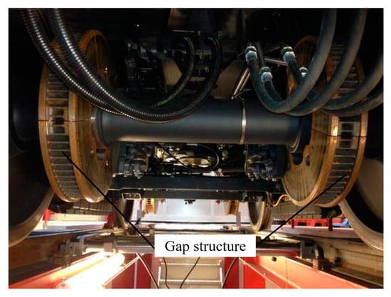
Figure 1.
Ventilated brake discs for high-speed trains.
To improve the braking efficiency of ventilated brake discs, many scholars have con-ducted more in-depth research on the temperature and stress distribution of brake discs generated by frictional heat during the braking process. Sainath et al. used finite-element analysis to model the frictional heat generation of brake discs and obtained their heat flux and nodal temperature distribution [1]. Qi et al. established a coupled model of the thermal structure of a ventilated brake disc, analysed the transient temperature field of the disc under braking conditions, and obtained the temperature variation curves of the disc along the radial and circumferential directions [2]. Belhocine et al. used a thermal-structural coupling method to carry out transient thermal analysis of ventilated brake discs to obtain the temperature and stress distribution of discs of different materials during the braking process, respectively [3]. Heerok et al. used the finite-element method to analyse the effect of the brake pad position on the brake disc temperature during the braking process. They obtained the temperature between the brake disc and the brake pad and the stress distribution law [4]. On this basis, some scholars considered the influence of different parameters on the brake disc temperature and stress distribution. Yang et al. obtained the temperature field distribution of brake discs under ramp braking conditions by considering the friction coefficient and slope variation [5]. Carmona et al. combined modal reduction, the conjugate gradient method, and the adjoint method to predict brake disc heat flux changes over time, obtaining the temperature change at different locations [6]. Mithlesh et al. analysed the stress distribution of brake discs during the braking process and showed that changing the contact area between the disc and brake pad can effectively reduce stress [7]. Dubale et al. carried out numerical simulations of heat transfer analysis on different brake discs. They obtained the temperature and stress distribution of different kinds of discs under emergency braking conditions [8].To improve the accuracy of the finite-element model, Bauzin et al. used the Fourier and Hankel integral transform to calculate the heat transfer problem in the braking process and obtain the temperature distribution of the brake disc [9]. Grzes proposed a method for calculating the maximum temperature of the friction surface of a brake disc during repeated braking, and the results showed that the maximum point temperature decreases as the number of brakes increases [10]. Zhang et al. proposed a displacement gradient cycle method for loading frictional heat flow and established a three-dimensional transient heat transfer finite-element model for brakes. The analysis results showed that the temperature decreases in a counterclockwise direction from the contact position between the brake disc and the brake pad [11]. Jiregna et al. performed a coupled thermal-structural analysis of the brake disc based on the FEM method. They obtained the temperature gradient distribution of the brake disc and the maximum temperature on the friction surface of the brake disc [12]. Although the principle of frictional heat generation in the braking process of the brake disc has been studied in-depth, the temperature field and stress field distribution laws under different working conditions have been obtained. However, the energy generated by the frictional work of the brake disc in the braking process affects the temperature and stress changes of the disc at different braking moments. The specific values of the energy generated and the influence of the variation pattern on the temperature distribution and stress fields have not been considered, resulting in some differences in the distribution of the temperature and stress fields obtained.
Most heat generated by friction during the braking process is dissipated in heat transfer to the different media. Researchers have studied the many factors that affect the ability of brake discs to dissipate heat. Yan et al. developed a numerical model and performed heat transfer measurements on standard commercial brake discs. The results showed that enhanced airflow properties around the brake disc increased the heat dissipation area and improved the heat dissipation capacity of the brake disc [13]. García-León et al. used the mathematical theory of heat transfer and numerical calculations to study ventilated brake discs. The results showed that the faster air circulates through the internal structure of a ventilated brake disc, the higher its heat dissipation rate during braking [14]. Fomina et al. used CFD simulations to analyse the flow field of the internal structure of a ventilated brake disc. The results showed that the flow state of the fluid had a significant effect on the thermal performance of the brake disc [15]. Duan et al. conducted numerical simulation on the temperature distribution of the battery cooling system and found that increasing the inlet water flow rate can significantly improve the heat transfer capacity of the battery [16]. To explore the influence of different parameters on heat dissipation capacity, Zhang et al. analysed the convective heat transfer coefficient of a brake disc. They established a relationship between the Nusser numbers, Reynolds number, and the disc-to-wheel-diameter ratio to obtain a more accurate convective heat transfer coefficient for the heat dissipation process of the brake disc [17]. Kumar et al. analysed the effect of varying Reynolds numbers on the thermal convection of brake discs. The brake disc temperature distribution was obtained in laminar flow and forced convection [18]. Moraveji et al. used numerical methods to study the influence of different structural parameters of vortex tube on temperature and mass flow rate. The results showed that the increase of the number of vortex tube inlets would lead to the decrease of outlet temperature [19]. Esfe et al. discussed the effects of Reynolds number, temperature, nano particle volume fraction, nano particle diameter, and other parameters on convective heat transfer by using numerical methods and found that the addition of nano particles had a significant impact on the heat transfer characteristics [20]. Ghandouri et al. used the finite-element volume method to consider the influence of fins with different structures on temperature and heat transfer coefficient and found that the new type of fins enhanced the heat dissipation capacity [21]. Song et al. used the numerical analysis method to find that piercing on the fin increases the area of contact with the air, which is helpful to improve the heat dissipation performance [22]. You et al. used different treatment methods to form different microstructures on the surface of the heat sink and found that adding thermal radiation coating is helpful to improve the surface heat dissipation problem [23]. To reduce the error of simulation results, Stevens et al. used first-order differential equations to predict the temperature of the brake disc and obtained the pattern of variation of convection and radiation heat dissipation from the brake disc during the cooling process [24]. Mashayekhi et al. developed an engineering technology and found that the volume fraction of nano particles in conventional thermal fluid is increased, which can improve the heat transfer rate [25]. Toghraie proposed a numerical method to simulate the subcooled jet passing through the high-temperature surface [26]. It was found that increasing the water jet velocity and decreasing the fluid temperature would increase the convective heat transfer coefficient. Xu et al. proposed a heat-management system. It was found that the heat dissipation effect of this method is enhanced, and the temperature uniformity is satisfied [27]. Zhang et al. established a three-dimensional, consistent heat dissipation channel model with both heat conduction and fluid channels. It was found that the optimal heat dissipation parameters can improve the heat dissipation performance of electronic equipment [28].
In summary, most of the research on ventilated brake discs has focused on the process of frictional heat generation, the distribution of temperature and stress fields, and the factors affecting their heat dissipation. During the braking process, the energy generated and dissipated into the air by the brake disc due to frictional work is constantly changing. Energy changes affect brake disc temperature and stress changes. The above studies seldom consider the simultaneity of the heat generation and heat dissipation of the ventilated brake disc during the braking process. The influence of its numerical value and variation law on the temperature field and stress field distribution has not been considered. The temperature and stress distribution of the ventilated brake disc were obtained inaccurately. As a result, the thermal decay resistance of the ventilated brake disc cannot be significantly improved. This paper takes the ventilated brake disc of the high-speed train as the research object. The forced convection heat dissipation form of the outer surface of the ventilated brake disc and the air is considered. The frictional contact between the brake disc and the brake pads generates energy. At the same time, the internal gap structure of the brake disc dissipates energy through contact with the air. The generation and dissipation of energy are studied from the perspective of functional conversion. The temperature and stress distribution on the surface of the ventilated brake disc and the internal clearance structure, and its variation with time is studied. During the braking process, the time-varying law of the heat generation and heat dissipation energy of the ventilated brake disc is obtained.
2. Mathematical Description of the Braking Process for High-Speed Trains
2.1. Characterization of the Three Heat Transfer Forms in the Braking Process
During the braking process, the macroscopic energy change of high-speed train braking is the process of converting mechanical energy into internal energy. At the same time, the internal energy of the ventilated brake disc is constantly dissipated into the air in the form of thermal convection and thermal radiation under the effect of forced convection of the external air. This phenomenon is known as heat transfer. According to its physical nature, heat transfer [14] can be divided into three types, including thermal conduction, thermal convection, and thermal radiation. Heat transfer occurs when there is a temperature difference between the friction interface of the ventilated disc and the gap structure. The heat transfer depends on the distribution of the temperature field of the ventilated brake disc. Heat conduction is represented by Fourier’s law [29]:
where ϕcond is the conduction heat flux and represents the heat passing over the friction interface; T is the temperature; λ is the thermal conductivity; Acond is the contact area between the ventilated brake disc and the brake pad. is the heat flow density for heat conduction in the x-direction; “” indicates that the direction of heat transfer is opposite to the direction of the temperature gradient.
Thermal convection occurs only in a moving fluid (liquid or gas) medium. It is the action of heat transfer caused by the relative displacement of masses in a fluid and is expressed in terms of Newton’s law of cooling for convective heat transfer [14]:
where ϕconv is the amount of thermal convection; Aconv is the contact area between the ventilated disc and the air; h is the convective heat transfer coefficient between the ventilated disc and the air, and the greater the coefficient means, the higher the rate of heat transfer between the two media; ΔT is the temperature difference between the ventilated disc and the air, usually taking a positive value.
Thermal radiation is the phenomenon of an object radiating electromagnetic waves due to its temperature and is usually expressed by the Stefan–Boltzmann law [30] as follows:
where ϕrad is the amount of thermal radiation, ε is the emissivity of the object, σb is the Stephan–Boltzmann constant, σb = 5.67 × 10⁻⁸ W/m2 k4; Arad is the area exposed to thermal radiation; Tdisc is the temperature of the ventilated brake disc; Tenv is the ambient temperature around the ventilated brake disc.
During braking, heat energy is generated by friction between the ventilated brake disc and the brake pad, and the heat energy is transferred along the friction surface to the brake disc and the brake pad in the form of heat conduction, as shown by the red arrow in Figure 2. Due to the high braking speed of high-speed trains during the braking process, the brake disc and brake pad will form convective heat exchange with the surrounding air, dissipating most of the heat in the ventilated brake disc into the air, as shown by the yellow arrow in Figure 2. As the braking time continues, the surface temperature of the brake disc will continue to rise. When the surface temperature of the brake disc is high, the surface forms a radiation heat exchange with the surrounding air due to thermal radiation, as shown by the blue arrow in Figure 2.
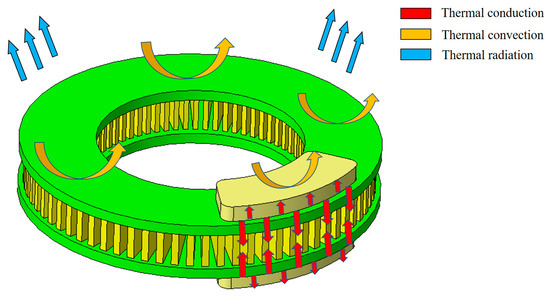
Figure 2.
Three heat transfer forms of the brake pad and the brake disc.
2.2. Physical Modelling of the Braking Process in High-Speed Trains
The working principle of the ventilated disc brake is that the kinetic energy generated by the operation of the train is transformed into thermal energy by the frictional action of the axially moving brake pads and rotating brake discs, which enables the braking of high-speed trains. To analyse the variation of temperature at each position during braking of a ventilated brake disc with time and the variation over time of the heat generated in the frictional contact zone and the heat dissipated by the surface of the ventilated brake disc, the following mathematical model is developed [31]:
where ρ is the density of the brake disc; CP is the specific heat capacity of the brake disc; u is the speed of the brake disc; ∇ is the differential operator; k is the heat transfer coefficient at different locations of the brake disc; Q is the heat source; Qted is the thermoelastic damping, and q is the heat transferred by the ventilated disc.
The surface of ventilated brake discs and brake pads make contact with air during the braking process. The friction disc surface of the ventilated brake disc is set up with the brake pad as a flat plate, creating forced convection with the outside air. The ventilated disc fan-shaped gap structure is a cylindrical bypass, creating forced convection with the outside air [32]. These are expressed as
where q0 is the energy dissipated by convective heat transfer h1 is the convective heat transfer coefficient of the friction surface of the brake disc, h2 is the convective heat transfer coefficient of the fan-shaped gap structure, Text is the external temperature, L is the difference between the outer diameter and inner diameter of the ventilated brake disc, D is the outer diameter of the fan-shaped gap structure, λair is the air thermal conductivity, and λair = 2.67 × 10⁻² W/(m·K); Pr is the Prandtl number, which is the number of causeless combinations indicating the interaction of energy and momentum migration processes in the fluid, indicating the relationship between the temperature boundary layer and the flow boundary layer, Pr = 0.701; and ReL and ReD are Reynolds numbers, which can be expressed as
where ρair is the density of air, ρair = 1.205 kg/m3, μ is aerodynamic viscosity, μ = 16 × 10−6 m2/s, and vair is the air flow rate.
The presence of radiant heat exchange between ventilated brake discs and brake pads is expressed as [30]
where ε is surface emissivity, and Tamb is ambient temperature.
During braking, a large amount of heat is generated on the friction disc surface in a short period of time, which forms a temperature gradient inside the brake disc. The thermal stress generated due to the influence of thermal field cooling can be expressed as [33]
where σ is thermal stress, α is the expansion coefficient, E is the elastic modulus, T0 is the initial temperature, and T is the temperature at some point in time.
2.3. Numerical Calculation of Energy Conversion of Ventilated Brake Discs
The braking power p can be given by the negative value of the time derivative of kinetic energy, which can be expressed as [34]
where m is the overall mass of the train, v is the train speed, and t is the braking time. A single train contains four axles, three ventilated discs, and six brake pads mounted on each axle, so the source of frictional heat on each brake pad, Pb, can be expressed as
where a is the acceleration during braking of the train.
The heat generated in the frictional contact zone of the brake disc and the heat dissipated on the outer surface of the disc can be expressed as
where Wprod is the energy generated in the contact area between a single brake pad and the disc, Wdiss is the energy dissipated by the disc in the form of convective heat transfer as well as thermal radiation, qrflux is the energy dissipated by thermal radiation, Atou is the area of the contact friction zone, Asur is the contact area between the disc and the outside world, and t0 is the train braking time.
During braking, mechanical energy changes into heat energy through friction. The heat energy of the ventilated brake disc is dissipated into the air in the form of convection heat transfer and changes with its heat generation and heat dissipation. According to Formula (15) and Formula (16), the heat energy it has can be expressed as
where W0 represents the heat possessed by the ventilated brake disc.
3. Finite-Element Modelling of Ventilated Brake Discs under the Action of Flow Fields
3.1. Model Simplification and Assumptions for Ventilated Brake Discs on High-Speed Trains
A single high-speed train usually has four axles. Three ventilated brake discs are mounted on each axle. The mechanical assembly of a high-speed train’s axle–disc connection consists of the brake devices, the shaft plate connectors, the axle, and the wheel, as shown in Figure 3. During the braking process, the brake pads are pressurized by a hydraulic machine, which pushes the brake pads against the brake discs to achieve the train’s braking.
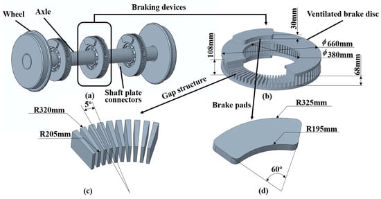
Figure 3.
High-speed train disc brake assembly diagram. (a) Axle-disc connection assembly; (b) Ventilated brake disc; (c) Gap structure of ventilated brake discs; (d) Brake pad.
To improve the efficiency of finite-element simulation calculations and improve the quality of meshing, components such as the bolts of the brake are simplified. Ignoring the internal and surface-related components of the brake, as each brake is subjected to the same braking torque during the braking process, a pair of ventilated brake discs and pads were selected for the study. The assembly and geometric parameters are shown in Figure 3b,d. Due to the complex internal clearance structure of the ventilated disc, a large amount of air is introduced into the clearance structure while the wheel is rotating, increasing the convective heat transfer capacity of the ventilated disc and accelerating heat dissipation. The ventilated discs have a total of 72 gap structures, uniformly distributed along the circumference, with the geometrical parameters shown in Figure 3b,c.
As the finite-element simulation cannot achieve complete uniformity with the actual working conditions, the following assumptions are made for the finite-element model:
- Ventilated brake discs in contact with the brake pad are the ideal interface;
- Ventilated brake discs, brake pads, and initial air temperature of 26.85 °C;
- The braking process follows a uniform deceleration motion;
- The ventilated brake disc and brake pad conform to Hooke’s law, and the friction coefficient remains unchanged during braking;
- Ignore phenomena such as wear and material damage to brake discs and pads during the braking process.
3.2. Finite-Element Modeling
The geometric model meshes with a free hexahedral network for the brake pad and the internal clearance structure of the ventilated brake disc and a free tetrahedral mesh for the ventilated brake disc surface. There are 59,744 cells in the model, consisting of 2520 hexahedral cells and 51,926 tetrahedral cells. The ventilated brake disc material is made of low-alloy steel. The brake pad material is made of copper-based powder metallurgy; the relevant parameters of the materials are shown in Table 1.

Table 1.
Material properties of the ventilated brake disc and brake pads.
The initial speed of the high-speed train before the emergency braking is set to V1 = 250 km/h, the radius of the train wheels is rb = 0.43 m, the initial temperature of the brake and environment is set to T = 26.85 °C, the total mass of a single carriage is m = 6.88 × 10⁴ kg under full load conditions, and the friction coefficient is set to μ0 = 0.25 when the brake pad is in contact with the ventilated brake disc. The rotational motion of the ventilated brake disc is converted into a translational movement in coordinate form and loaded onto the disc, thus realizing its braking process.
The heat generated by the brake disc and brake pad is loaded on the contact surface of the brake disc and brake pad in the form of a frictional heat source and is evenly distributed on the frictional contact surface. The brake disc friction contact surface and gap structure are set up as a longitudinal swept plate convection heat transfer boundary, a transverse swept tube boundary, and radiant heat exchange at all edges of the brake disc in contact with the air. The finite-element model of the high-speed train ventilated brake disc and brake pad was finally obtained by constraining the three degrees of freedom of the disc in the x, y, and z directions, as shown in Figure 4.
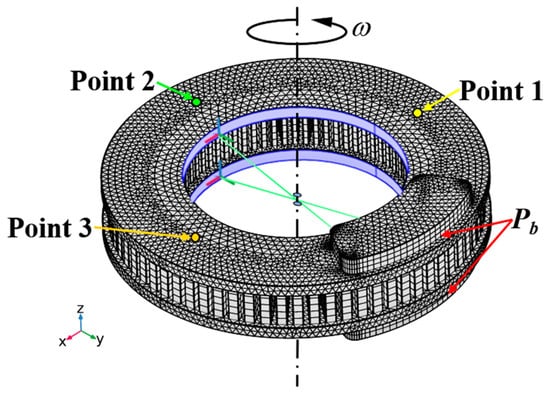
Figure 4.
Finite-element model of ventilated brake disc and brake pad.
Before the start of numerical simulation, it is necessary to check the grid independence [35]. Three coordinate points are selected on the ventilated brake disc friction surface, as shown in Figure 4. The coordinate points are, respectively, (−0.26, 0, 0.054), (0, −0.26, 0.054), and (0.26, 0, 0.054). It can be seen from Table 2 that the number of grids in Grid 3 and Grid 4 increases, but the change of the number of grids has little impact on the temperature nodes. Therefore, the third grid number is adopted for calculation in this paper.
Table 2.
Grid independence test.
3.3. Test Verification
Compared with the solid brake disc, the ventilated brake disc has a unique heat dissipation structure, which can quickly dissipate the heat energy inside the brake disc into the air. In order to verify the accuracy of the finite-element model, the brake test was completed on a 1:1 high-speed train brake-testing machine, as shown in Figure 5. The test function was applied to both drum brake and disc brake, so some parts of the testing machine were simplified in the simulation model. The braking initial velocity and braking pressure in the initial test condition are the same as those in the finite-element simulation condition. Therefore, the data results can provide validation for the simulation model. Using the thermocouple measurement method, a thermocouple was arranged at the theoretical friction radius of the brake disc to effectively collect the contact temperature of the brake disc. The comparison between the temperature measurement results of the thermocouple node and the simulation results is shown in Figure 6. The x-axis indicates braking time, and the y-axis indicates temperature.
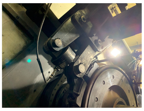
Figure 5.
High-speed train brake-testing machine.
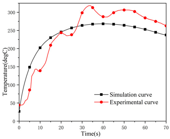
Figure 6.
Comparison of experimental and simulation results.
It can be seen from the figure that the maximum temperature value during the test differs by 19% from the simulated maximum temperature value at the same time. The initial temperature of the test is about 50 °C, and the initial temperature of the simulation is 26.85 °C. Before braking for 29 s, the contact between the brake disc and the brake pads is uneven during the test, resulting in a lower temperature-rise rate than in the simulation. However, after 29 s, the finite-element simulation considers that the ventilated brake disc is subjected to forced convection during the braking process, resulting in faster heat dissipation, so the temperature will be slightly lower than the test temperature. During the test, there is a vibration between the brake disc and the brake pad, resulting in fluctuations in the temperature measured by the thermocouple. Comprehensively considering the influence of the test error, the simulation temperature change curve of the ventilated brake disc and the test brake temperature change curve are both parabolic, and the temperature change law is the same, so the test results demonstrate the correctness of the simulation model.
4. Simulation Analysis Results and Discussion
In the simulated braking process in 70 s, the maximum temperature, speed, and acceleration curves of the ventilated brake disc during the braking process with time are shown in Figure 7. It can be obtained from the figure that the speed of the ventilated disc decreases evenly throughout the braking process, from 250 km/h to 0 km/h. The initial temperature is 26.85 °C and the highest temperature appears at 41 s of braking, and its maximum temperature reaches 268 °C. After the 70 s of braking, the brake disc stops rotating, at which time its maximum temperature is 239 °C. In the initial braking stage, due to the rapid rise in the temperature of the brake disc, the temperature of the friction surface of the brake disc rises rapidly. The gap structure temperature difference is significant so that the thermal stress reaches its maximum value. Still, with the increased braking time, heat transfer, and dissipation into the air, the temperature of the brake disc changes slowly so that its thermal stress gradually decreases.
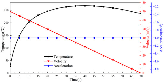
Figure 7.
Maximum temperature, velocity, and acceleration time variation curves.
4.1. Temperature Distribution Pattern during Braking
4.1.1. Analysis of Friction Surface between Ventilated Brake Disc and Brake Pad
Figure 8 shows the temperature field distribution of the ventilated disc at different braking moments. From the figure, it can be seen that the temperature of the ventilated disc increases and then decreases with the braking time, and the distribution is not uniform. The high-temperature zone is mainly concentrated on the friction surface of the ventilated brake disc and the brake pad, and the maximum temperature is related to the geometry of the brake pad contact position. As shown in Figure 8a, the friction surface in contact with the brake pad is at the highest temperature at the beginning of the braking period, reaching 29.5 °C, with heat transfer to other parts along the radial and axial directions. With the counter clockwise rotation of the brake disc, a temperature difference is formed between the disc contact friction surface and its surrounding surface. As the braking time increases, the heat generated by the frictional contact area is continuously transferred to the surrounding area, as shown in Figure 8b, causing the brake disc friction surface to form a ring-like temperature zone extension phenomenon. Figure 8c shows that the temperature generated by friction on the brake pad at the end of braking is transferred to the friction surface by heat transfer. During the braking process, the air around the friction surface of the brake disc is present in the form of turbulence, and the temperature of the friction surface reduces. The outer side of the brake disc friction surface has a higher linear velocity than the inner side, making the heat generated by friction on the outer side of the friction surface high. Still, the outer side has a larger contact area with the air compared to the inner side, making the heat dissipation effect on the outer side of the brake disc friction surface better under the joint action of the two, making the highest temperature of the friction surface concentrated near the friction radius. After braking, the temperature at the friction radius is 239 °C.
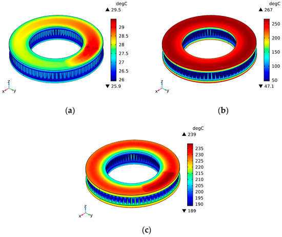
Figure 8.
Surface temperature clouds of ventilated discs at different braking moments. (a) Braking 0.05 s; (b) braking 35 s; (c) braking 70 s.
To make it easier to observe the temperature variation pattern on the friction surface of the ventilated brake disc, a three-dimensional position-time-temperature cloud was fitted along the radial direction to generate a three-dimensional map of the friction surface of the ventilated brake disc, as shown in Figure 9. In Figure 9, the x-axis indicates the radial position of the surface of the ventilated disc; the y-axis indicates braking time and the z-axis temperature. The temperature reaches a maximum of 268 °C at 41 s. Combined with Figure 8a, the heat generated by the friction surface of the ventilated disc is higher than the heat dissipated by convective heat dissipation with air before 41 s, and combined with Figure 8b,c, the heat dissipated by convective heat dissipation on the friction surface of the ventilated disc is higher than the heat generated after 41 s, so its temperature tends to decrease. The temperature decreases from the frictional contact zone to the inner and outer diameter. When the brake disc speed is low, the adhesion of the air is more excellent in the brake disc surface to form laminar flow; when the brake disc speed is high, the air on the brake disc surface follows an irregular flow, creating turbulence. The air pattern on its surface influences the heat dissipation on the surface of the brake disc. Under high-speed rotation, a convective heat exchange exists between the ventilated disc and the air. The contact area between the outer diameter and the atmosphere is larger than between the inner diameter and the air. However, the heat generated outside the contact friction zone is higher than that generated inside the area.
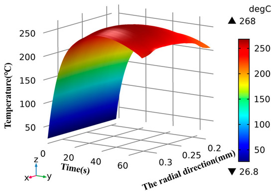
Figure 9.
Three-dimensional cloud of time-temperature along the radial direction of a ventilated brake disc.
4.1.2. Analysis of Internal Gap Structure of Ventilated Brake Discs
During the braking process of a high-speed train, the high-speed rotating ventilated brake disc introduces the surrounding air into its internal gap structure. Due to the high fluid-flow velocity, the irregular flow along the gap structure forms turbulence. At the same time, the air is thrown out by the centrifugal force generated by the rotating disc, and the heat of the ventilated disc is carried away. The internal gap structure of the ventilated disc dissipates the heat generated by the braking process in the form of convective heat transfer. The highest temperature of the braking process occurs at the friction contact surface at 41 s of braking, and the temperature field cloud is shown in Figure 10. The axial section temperature cloud of the gap structure at 41 s and its section amplification temperature cloud are shown in Figure 11.
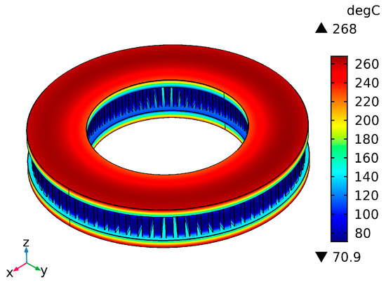
Figure 10.
Temperature cloud at 41 s of braking for ventilated discs.
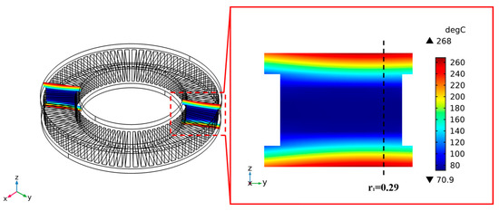
Figure 11.
Temperature clouds in the axial section of the interstitial structure.
It can be seen from Figure 8 that the high-temperature zone is mainly distributed in the contact friction zone between the brake disc and the brake pad, with the highest temperature reaching 268 °C. At the same time, under the action of heat conduction, the temperature generated in the friction contact zone is continuously transferred to the gap structure along the axial direction, reaching 100 °C in the middle of the gap structure. It can be concluded from Figure 11 that the heat generated on the outer side of the friction surface makes the temperature transfer along the axial side of the gap structure more evident than the gradient on the inner side. During the braking process, the ventilated disc is subjected to a pair of symmetrical brake pads, resulting in a balanced temperature distribution along the axial direction. To make it easier to observe the temperature changes in the gap structure of the ventilated disc, a three-dimensional position-time-temperature cloud was fitted along the axial direction at the highest temperature point of the disc surface during the entire braking process, as shown in Figure 12. In Figure 12, the x-axis represents the axial position of the ventilated disc clearance structure, the y-axis represents the braking time, and the z-axis represents the temperature. The temperature of the part of the ventilated disc clearance structure closer to the disc surface rises first and then falls. In the initial stage of braking, the amount of the gap structure is far from the disc surface, and the heat generated by the contact friction contact area has not yet been transferred to the centre of the gap structure. In contrast, the air introduced inside the gap structure forms an irregular flow on its surface, taking away its surface heat. The heat dissipated by the gap structure in convective heat transfer is higher than the heat transferred to the gap structure. The temperature of the gap structure part drops continuously during the initial braking stage.
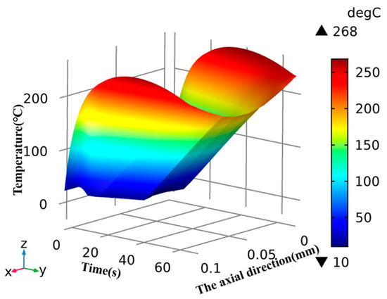
Figure 12.
Three-dimensional time-temperature cloud along the axial direction of the ventilated brake disc gap structure.
To more intuitively study the temperature variation law of the gap structure with time, the temperature variation with time of the nodes selected at equal spacing along the axial direction at the radius of the highest temperature point of the disc surface during the whole braking process, according to Figure 11, is shown in Figure 13. It can be seen from Figure 13 that the temperature of the nodes near the friction contact surface changes significantly with time. In the initial braking stage, the heat generated by the friction between the ventilated disc and the brake pad is higher than the heat dissipated by the ventilated brake in convective heat dissipation. Hence, its temperature rises continuously with time. In the node near the middle of the gap structure, in the initial stage of braking, due to the high-speed rotation of the brake disc, the gap structure of the ventilated disc introduces a large amount of air, forming turbulence under the action of high-speed fluid, and the heat dissipated by convection heat dissipation on its surface is higher than the heat transferred from the friction contact surface to the node due to heat conduction, so the temperature of the node near the centre of the gap structure drops first. As the braking time increases, the heat generated in the friction contact area of the ventilated disc is continuously transferred from the friction disc surface to the gap structure using heat conduction. At the same time, the speed of the disc decreases, and the airflow rate introduced into its gap structure gradually decreases, making the convective heat exchange between its surface and the air less efficient. As a result, the convective effect between the gap structure and the air is weakened, so the temperature of the gap structure is on the rise, as the energy transferred by heat conduction is greater than the energy dissipated in the form of convective heat dissipation after about 10 s.
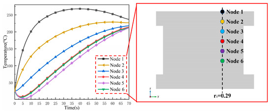
Figure 13.
Temperature profile of the nodes along with the axial distribution of the gap structure as a function of time.
4.2. Stress Distribution Pattern during Braking
4.2.1. Analysis of Friction Surface between Ventilated Brake Disc and Brake Pad
From the results of the temperature field analysis, it can be seen that during the braking process, the form and rate of airflow through the outer surface of the brake disc of the high-speed rotating disc are different, which makes the convective heat dissipation of the brake disc surface and the clearance structure and air different, resulting in different rates of temperature change on its surface. Under the effect of thermal expansion and contraction, higher thermal stress will be generated at the connection between the brake disc surface and the gap structure; Figure 14 shows the stress cloud diagram of the surface of the ventilated brake disc at different braking moments. The initial stage is shown in Figure 14a; as the ventilated disc is subjected to the brake pad’s friction, the high-stress area is mainly concentrated in the friction contact area between the ventilated disc and the brake pad. At the same time, the other locations have a more uniform stress distribution. However, with the increase in braking time, the friction surface stress shows a circular distribution.
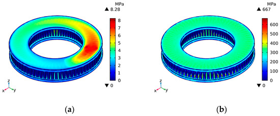
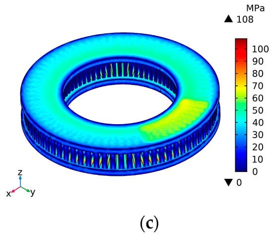
Figure 14.
Stress cloud on the surface of a ventilated brake disc at different braking moments. (a) Braking 0.05 s; (b) braking 35 s; (c) braking 70 s.
Figure 15 shows a three-dimensional position-time-stress cloud along the radial direction of the friction surface of the ventilated brake disc. In Figure 15, the x-axis represents the radial position of the surface of the ventilated brake disc, the y-axis represents the time by braking, and the z-axis represents the equivalent force. Compared with Figure 9, it can be seen that the rate of temperature rise in the friction contact area is higher than the rate of temperature rise around it; the air forms turbulence on the surface around it, taking away most of the brake disc friction surface temperature, but the friction contact area continuously generates heat in the brake disc surface to form a temperature difference, resulting in the stress induced in the friction contact area being higher than the stress around it. The highest stress in the friction contact area reaches 439 MPa. Its stress distribution law is consistent with the distribution law of the temperature field.
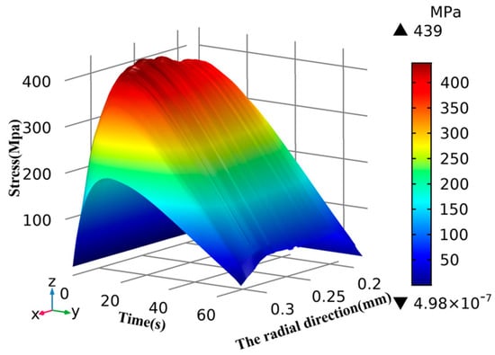
Figure 15.
Three-dimensional cloud of time-stress along the radial direction of a ventilated brake disc.
4.2.2. Analysis of Internal Gap Structure of Ventilated Brake Discs
The gap structure is the central part of the ventilated brake disc heat dissipation; in its connection with the disc surface of the brake disc, it is easy to produce significant stress, and during the braking of 19 s, in the gap structure and the disc surface connection, the maximum pressure is reached, and its surface equivalent force cloud diagram is shown in Figure 16. The surface equivalent stress cloud is also shown in Figure 16. The axial, tangential stress field cloud of the gap structure is shown in Figure 17. In the whole braking process, because of the brake disc surface and heat dissipation rib connection, air mobility is poor, and local irregular flow is easily formed. The surface temperature at the connection is not easy to be lost. The surrounding air has strong fluidity, and the temperature loss rate at the junction is inconsistent, resulting in its more considerable stress. Combined with Figure 15, it can be concluded that the maximum pressure of 773 MPa is generated at the connection between the disc surface of the brake disc and the clearance structure.
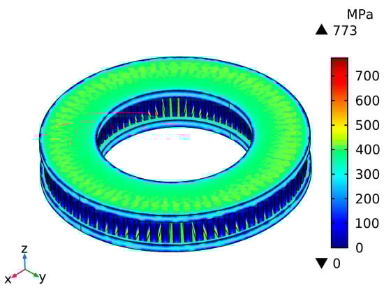
Figure 16.
Ventilated disc surface stress cloud at 19 s braking.
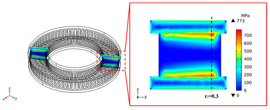
Figure 17.
Stress cloud in the axial section of a ventilated brake disc.
To make it easier to observe the stress variation in the ventilated brake disc clearance structure, a three-dimensional position-time-stress cloud was plotted along with the axial position at the radius of the maximum stress point, as shown in Figure 18. In Figure 18, the x-axis represents the axial position of the ventilated disc gap structure, the y-axis represents the time by braking, and the z-axis represents the stress. Combined with Figure 13, the middle part of the gap structure has a large contact area with the air, and its surface airflow is better. In the early braking stage, the air flows through its surface and takes away more heat, forming a temperature difference with the part near the disc surface, leading to a rise in stress. As the disc speed decreases, the airflow rate inside the gap structure decreases so that the energy dissipated on its surface decreases. At the same time, the heat generated in the friction contact area is continuously transferred to the gap structure so that the difference in temperature dissipation rate is more minor. Hence, the stress shows a decreasing trend again.
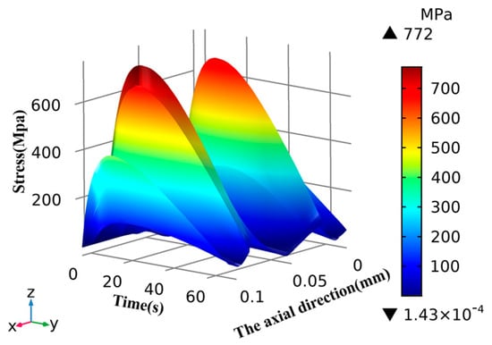
Figure 18.
Three-dimensional cloud of time-stress along the axial direction of a ventilated brake disc gap structure.
4.3. Heat Production and Heat Dissipation Pattern during Braking
During the braking process of high-speed trains, the ventilated brake disc constantly generates heat in the contact friction zone, and at the same time, the surface of its structure is affected by turbulent air, which dissipates the heat of the disc into the air continuously, as shown in Figure 19. The ventilated brake disc in the braking process generates and dissipates heat with time-change curve. From the figure, it can be seen in the braking period that its heat production rises more violently; Figure 8 shows that in the early stage of braking, the temperature rise more apparent; this is due to the high-speed train’s initial speed being higher. It can be seen from Formula (15) and Formula (16) that more heat is generated by the friction between the ventilated brake disc and the brake pad in unit time, which makes the energy of the ventilated brake disc rise faster As the braking time increases, the heat generated by friction decreases due to the decreasing speed of the high-speed train, and the rate of growth of the energy of the ventilated disc decreases. The air around the ventilated disc flows differently and carries away the energy transferred from its interior to the surface. Through convection heat dissipation as well as thermal radiation and dissipation into the air, and from the graph of the change curve, the difference between heat production and heat dissipation compared to the heat production curve can be seen in the middle and late stages of braking. Heat dissipation has a significant effect on the energy of ventilated brake discs, resulting in the temperature of the ventilated brake disc after 41 s of braking showing a decreasing trend.
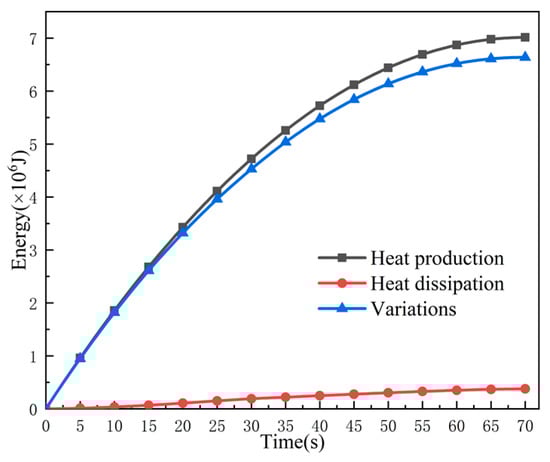
Figure 19.
Heat production–heat dissipation curve with time.
5. Conclusions
This paper deduces the energy conversion of the heat generation-radiation process of the ventilated brake disc of a high-speed train during the braking process. Three different heat transfer modes were considered for transient thermal analysis of ventilated disc brakes. The heat generation-dissipation theory was used to analyse the temperature and stress distribution of the friction disc surface of the ventilated brake disc and the gap structure from the perspective of function conversion. The following conclusions were obtained:
- During the braking process of high-speed trains, the temperature of the friction surface of the ventilated brake disc shows a circular distribution, with the highest temperature reaching 268 °C. The high-temperature area mainly concentrates on the friction contact area and gradually decreases along the radial direction. A high-velocity flow field exists around the gap structure portion. Under the combined action of heat conduction, heat radiation, and heat convection, its temperature shows a trend of first decreasing and then increasing with time.
- Ventilated brake disc friction-surface stress distribution and temperature distribution trend are consistent. Different parts of it have different contact areas with the air, so they have different heat dissipation rates. The gap structure has a larger heat dissipation rate around the connection between the gap structure and the disc surface of the brake disc. The maximum stress at the connection reaches 773 MPa.
- Combined with the numerical calculation of the energy conversion of the ventilated brake disc during braking, the variation law of the heat production and heat dissipation energy of the ventilated brake disc with time during braking is obtained: The heat generated in the friction contact zone increases nonlinearly; the heat dissipated by convection heat transfer and thermal radiation on the outer surface of ventilated brake disc increases linearly; and under the combined effect of heat generation and heat dissipation, the heat of the ventilated brake disc increases with the increase of braking time, but its growth rate decreases gradually due to the continuous enhancement of convection heat transfer.
Author Contributions
Z.S. and J.L. conceived the idea of this work; J.L. and J.Y. conducted the simulation; data curation, Q.H.; original draft preparation, J.L.; review and editing, S.Z. and Y.L. All authors have read and agreed to the published version of the manuscript.
Funding
This research was funded by Dalian Science and Technology Innovation Fund (No. 2021JJ12GX009), Scientific Research Project of the Education Department of Liaoning Province (No. LJKZ0479), Transportation Science & Technology Project of the Transportation Department of Liaoning Province (No. 202148), and Applied Basic Research Program of Liaoning Province (No. 2022030464-JH2/1013).
Institutional Review Board Statement
Not applicable.
Informed Consent Statement
Not applicable.
Data Availability Statement
The data used to support the findings of this study are available from the corresponding author upon request.
Conflicts of Interest
The authors declare that there are no conflict of interest regarding the publication of this paper.
References
- Sainath, A.; Dehadray, P.M.; Bharath, P.; Rao, L.B. The thermal and stress analysis of disc brake. In Proceedings of the IOP Conference Series on Materials Science and Engineering, Chennai, India, 30–31 October 2020. [Google Scholar]
- Jian, Q.F.; Shui, Y. Numerical and experimental analysis of transient temperature field of ventilated disc brake under the condition of hard braking. Int. J. Therm. Sci. 2015, 122, 115–123. [Google Scholar] [CrossRef]
- Belhocine, A.; Abdullah, O.I. A thermomechanical model for the analysis of disc brake using the finite element method in frictional contact. J. Therm. Stresses 2020, 43, 305–320. [Google Scholar] [CrossRef]
- Hong, H.; Kim, G.; Lee, H.; Kim, J.; Lee, D.; Kim, M.; Suh, M.; Lee, J. Optimal location of brake pad for reduction of temperature deviation on brake disc during high-energy braking. J. Mech. Sci. Technol. 2021, 35, 1109–1120. [Google Scholar] [CrossRef]
- Yang, Y.Q.; Wu, B.; Shen, Q.; Xiao, G.W. Numerical simulation of the frictional heat problem of subway brake discs considering variable friction coefficient and slope track. Eng. Fail. Anal. 2021, 130, 105794. [Google Scholar] [CrossRef]
- Carmona, S.; Rouizi, Y.; Quéméner, O.; Joly, F.; Neveu, A. Estimation of heat flux by using reduced model and the adjoint method. Application to a brake disc rotating. Int. J. Therm. Sci. 2018, 131, 94–104. [Google Scholar] [CrossRef]
- Mithlesh, S.; Tantray, Z.A.; Bansal, M.; Kotte, V.; Kumar, K.P.; Kurakula, V.S.; Singh, M. Improvement in performance of vented disc brake by eometrical modification of rotor. Mater. Today: Proc. 2021, 47, 6054–6059. [Google Scholar]
- Kumaran, S.; Dubale, H.; Paramasivam, V.; Gardie, E.; Chekol, E.R.; Senthil, E. Numerical investigation of thermo-mechanical properties for disc brake using light commercial vehicle. Mater. Today Proc. 2021, 46, 7548–7555. [Google Scholar]
- Bauzin, J.G.; Laraqi, N. Three-dimensional analytical calculation of the temperature in a brake disc of a high-speed train. Appl. Therm. Eng. 2019, 154, 668–675. [Google Scholar] [CrossRef]
- Grzes, P. Maximum temperature of the disc during repeated braking applications. Adv. Mech. Eng. 2019, 11, 1687814019837826. [Google Scholar] [CrossRef]
- Zhang, S.F.; Yin, J.; Liu, Y.; Liu, N.; Sha, Z.H.; Wang, Y.N.; Rolfe, B. Thermal–structural coupling analysis of brake friction pair based on the displacement gradient circulation method. Adv. Mech. Eng. 2018, 10, 1687814018773816. [Google Scholar] [CrossRef]
- Jiregna, I.T.; Lemu, H.G. Thermal stress analysis of disc brake using analytical and numerical methods. In Proceedings of the IOP Conference Series on Materials Science and Engineering, Moscow, Russia, 25–26 November 2021. [Google Scholar]
- Yan, H.B.; Feng, S.S.; Lu, T.J.; Xie, G.N. Experimental and numerical study of turbulent flow and enhanced heat transfer by cross-drilled holes in a pin-finned brake disc. Int. J. Therm. Sci. 2017, 118, 355–366. [Google Scholar] [CrossRef]
- García-León, R.A.; Afanador-García, N.; Gómez-Camperos, J.A. Numerical study of heat transfer and speed air flow on performance of an auto-ventilated disc brake. Fluids 2021, 6, 160. [Google Scholar] [CrossRef]
- Fomina, Y.; Pavelčík, V. Airflow simulation when braking with a disc brake. In Proceedings of the IOP Conference Series on Materials Science and Engineering, Bardejov, Slovakia, 13–15 September 2021. [Google Scholar]
- Duan, J.B.; Zhao, J.P.; Li, X.K.; Panchal, S.; Yuan, J.L.; Fraser, R.; Fowler, M. Modeling and Analysis of Heat Dissipation for Liquid Cooling Lithium-Ion Batteries. Energies 2021, 14, 4187. [Google Scholar] [CrossRef]
- Zhang, Y.H.; Jin, X.; He, M.; Wang, L.; Wang, Q.W.; Wang, L.B.; Wu, Y. The convective heat transfer characteristics on outside surface of vehicle brake disc. Int. J. Therm. Sci. 2017, 120, 366–376. [Google Scholar] [CrossRef]
- Kumar, S.; Rajagopal, T.K.R. Effect of Reynold’s number on effective heat transfer dissipation of braking system. Mater. Today Proc. 2021, 46, 8455–8460. [Google Scholar] [CrossRef]
- Moraveji, A.; Toghraie, D. Computational fluid dynamics simulation of heat transfer and fluid flow characteristics in a vortex tube by considering the various parameters. Int. J. Heat Mass Transf. 2017, 113, 432–443. [Google Scholar] [CrossRef]
- Esfe, M.H.; Akbari, M.; Toghraie, D.; Karimipour, A.; Afrand, M. Effect of nanofluid variable properties on mixed convection flow and heat transfer in an inclined two-sided lid-driven cavity with sinusoidal heating on sidewalls. Heat Transf. Res. 2014, 45, 409–432. [Google Scholar] [CrossRef]
- Ghandouri, I.E.; Maakoul, A.E.; Saadeddine, S.; Meziane, M. Thermal performance of a corrugated heat dissipation fin design: A natural convection numerical analysis. Int. J. Heat Mass Transf. 2021, 180, 121763. [Google Scholar] [CrossRef]
- Song, G.H.; Kim, D.H.; Song, D.H.; Sung, J.B.; Yook, S.J. Heat-dissipation performance of cylindrical heat sink with perforated fins. Int. J. Therm. Sci. 2021, 170, 107132. [Google Scholar] [CrossRef]
- You, Y.X.; Zhang, B.B.; Tao, S.L.; Liang, Z.H.; Tang, B.; Zhou, R.; Yuan, D. Effect of Surface Microstructure on the Heat Dissipation Performance of Heat Sinks Used in Electronic Devices. Micromachines 2021, 12, 265. [Google Scholar] [CrossRef]
- Stevens, K.; Tirovic, M. Heat dissipation from a stationary brake disc, Part 1: Analytical modelling and experimental investigations. J. Mech. Eng. Sci. 2018, 232, 1707–1733. [Google Scholar] [CrossRef]
- Mashayekhi, R.; Khodabandeh, E.; Akbari, O.A.; Toghraie, D.; Bahiraei, M.; Gholami, M. CFD analysis of thermal and hydrodynamic characteristics of hybrid nanofluid in a new designed sinusoidal double-layered microchannel heat sink. J. Therm. Anal. Calorim. 2018, 134, 2305–2315. [Google Scholar] [CrossRef]
- Toghraie, D. Numerical thermal analysis of water–s boiling heat transfer based on a turbulent jet impingement on heated surface. Low-Dimens. Syst. Nanostruct. 2016, 84, 454–465. [Google Scholar]
- Xu, X.M.; Tang, W.; Fu, J.Q.; Li, R.Z.; Sun, X.D. Plate flat heat pipe and liquid-cooled coupled multistage heat dissipation system of Li-ion battery. Int. J. Energy Res. 2019, 43, 1133–1141. [Google Scholar] [CrossRef]
- Zhang, Z.M.; Feng, H.J.; Chen, L.G.; Ge, Y.L. Multi-objective constructal design for compound heat dissipation channels in a three-dimensional trapezoidal heat generation body. Int. Commun. Heat Mass Transf. 2021, 127, 105584. [Google Scholar] [CrossRef]
- Hua, Y.C.; Zhao, T.; Guo, Z.Y. Optimization of the one-dimensional transient heat conduction problems using extended entransy analyses. Int. J. Heat Mass Transf. 2018, 116, 166–172. [Google Scholar] [CrossRef]
- De Lima, J.A.S.; Santos, J. Generalized Stefan-Boltzmann law. Int. J. Theor. Phys. 1995, 34, 127–134. [Google Scholar] [CrossRef]
- Knüttel, D.; Baraldo, S.; Valente, A.; Wegener, K.; Carpanzano, E. Model based learning for efficient modelling of heat transfer dynamics. Procedia CIRP 2021, 102, 252–257. [Google Scholar] [CrossRef]
- Surachai, S.; Goldstein, R.J. Forced convection heat transfer from a circular cylinder in crossflow to air and liquids. Int. J. Heat Mass Transf. 2004, 47, 4795–4805. [Google Scholar]
- Vaferi, K.; Nekahi, S.; Vajdi, M.; Moghanlou, F.S.; Shokouhimehr, M.; Motallebzadeh, A.; Sha, J.J.; Asl, M.S. Heat transfer, thermal stress and failure analyses in a TiB2 gas turbine stator blade. Ceram. Int. 2019, 15, 19331–19339. [Google Scholar] [CrossRef]
- Coulibaly, A.; Zioui, N.; Bentouba, S.; Kelouwani, S.; Bourouis, M. Use of thermoelectric generators to harvest energy from motor vehicle brake discs. Case Stud. Therm. Eng. 2021, 28, 101379. [Google Scholar] [CrossRef]
- Tu, J.L.; Qi, C.; Li, K.; Tang, Z.B. Numerical analysis of flow and heat characteristic around micro-ribbed tube in heat exchanger system. Powder Technol. 2022, 395, 562–583. [Google Scholar] [CrossRef]


Publisher’s Note: MDPI stays neutral with regard to jurisdictional claims in published maps and institutional affiliations. |
© 2022 by the authors. Licensee MDPI, Basel, Switzerland. This article is an open access article distributed under the terms and conditions of the Creative Commons Attribution (CC BY) license (https://creativecommons.org/licenses/by/4.0/).