1. Introduction
Hypersonic vehicles are subjected to extremely harsh aerodynamic heating during the atmospheric entry/reentry stage. A heat shield, called a thermal protection system (TPS), is utilized to maintain the aerodynamic shape and protect the underlying material and internal structure within acceptable temperature limits [
1,
2,
3]. The TPS is the key feature that makes a hypersonic vehicle lightweight, reusable, and maintainable. Therefore, the optimization design of the TPS has become more prominent in the early stages of hypersonic vehicle development [
4].
Generally, the design of the TPS is mainly carried out under the assumption that the involved parameters are deterministic [
5,
6,
7,
8,
9,
10]. However, multi-sources of uncertainties inherently exist in the design of the TPS, including materials dispersion, loads fluctuation, fabrication tolerance, approximation of boundary conditions, and so on [
11]. It has been well acknowledged that the presence of uncertainties would markedly influence the thermal responses of the TPS, and the effects of uncertainties must be carefully considered in the design of the TPS. Even a slight variability of the thermal responses may cause a serious flight accident [
12]. Kumar [
13] stated that uncertainties are inherently associated with the TPS performance, and it is critical to consider the variations during the optimization to ensure the safety of the final design. Wright [
14] and Ravishankar [
15] emphasize the significance of uncertainty analysis by conducting a probabilistic analysis of aerothermal and thermal protection material responses with the Monte Carlo method. Thus, the uncertainty is an important issue that should be comprehensively taken into account in the design phase of the TPS.
Over the past few years, the uncertainty-based optimization design for the TPS of hypersonic vehicles have attracted much attention. Kolodziej [
16] estimated thermal reliability from an assessment of TPS uncertainties. Kumar [
17] investigated the probabilistic optimization of integrated TPS, that combines the thermal protection function with the structural load carrying function. Antonio [
18] presented a statistical methodology to conduct a size optimization for the TPS of atmospheric entry vehicles. Zhu et al. [
19] established a six sigma robust design optimization based on a surrogate model for the TPS, in order to improve the reliability and robustness while considering the uncertainties. Dec and Mitcheltree [
20] applied the Monte Carlo Simulation technique to determine the TPS margins with probabilistic design. Bose et al. [
21] developed this technique to the thermochemical uncertainty and sensitivity analysis of an ablative TPS during a Titan atmospheric entry. Chen et al. [
22] identified the multi-sources of uncertainties in the diverse TPS materials and aerothermal environments, and then performed the TPS thickness optimization.
Nevertheless, according to the current research state described above, there are still some issues that need to be further investigated.
(1) Most researches on the uncertainty-based optimization design of the TPS consider the structural size optimization design with the assumed aerodynamic shape and aerodynamic heating loads. It means that the structural optimization and aerodynamic shape optimization of the TPS are separated. However, the structural optimization of the TPS is highly dependent on the aerodynamic shape and the corresponding aerodynamic loads, which act as the geometric boundary constrains and thermal loads of the TPS, respectively. Consequently, an uncertainty-based comprehensive optimization design, integrating the aerodynamic shape optimization and the TPS structural optimization, is more meaningful than any individual optimization design in practical engineering.
(2) The optimization design of the TPS in most literature is based on the stochastic models, which always need sufficient information to determine the density function. However, the information is often insufficient in the complex engineering structures like the TPS of a hypersonic vehicle. In this case, the non-probabilistic models [
23,
24,
25,
26], which only need the bounds information of uncertainties, are well suitable for dealing with the uncertain-but-bounded uncertainties. Compared with the stochastic model, studies on the non-probabilistic, model-based optimization design for the TPS of the hypersonic vehicle are still rare at present.
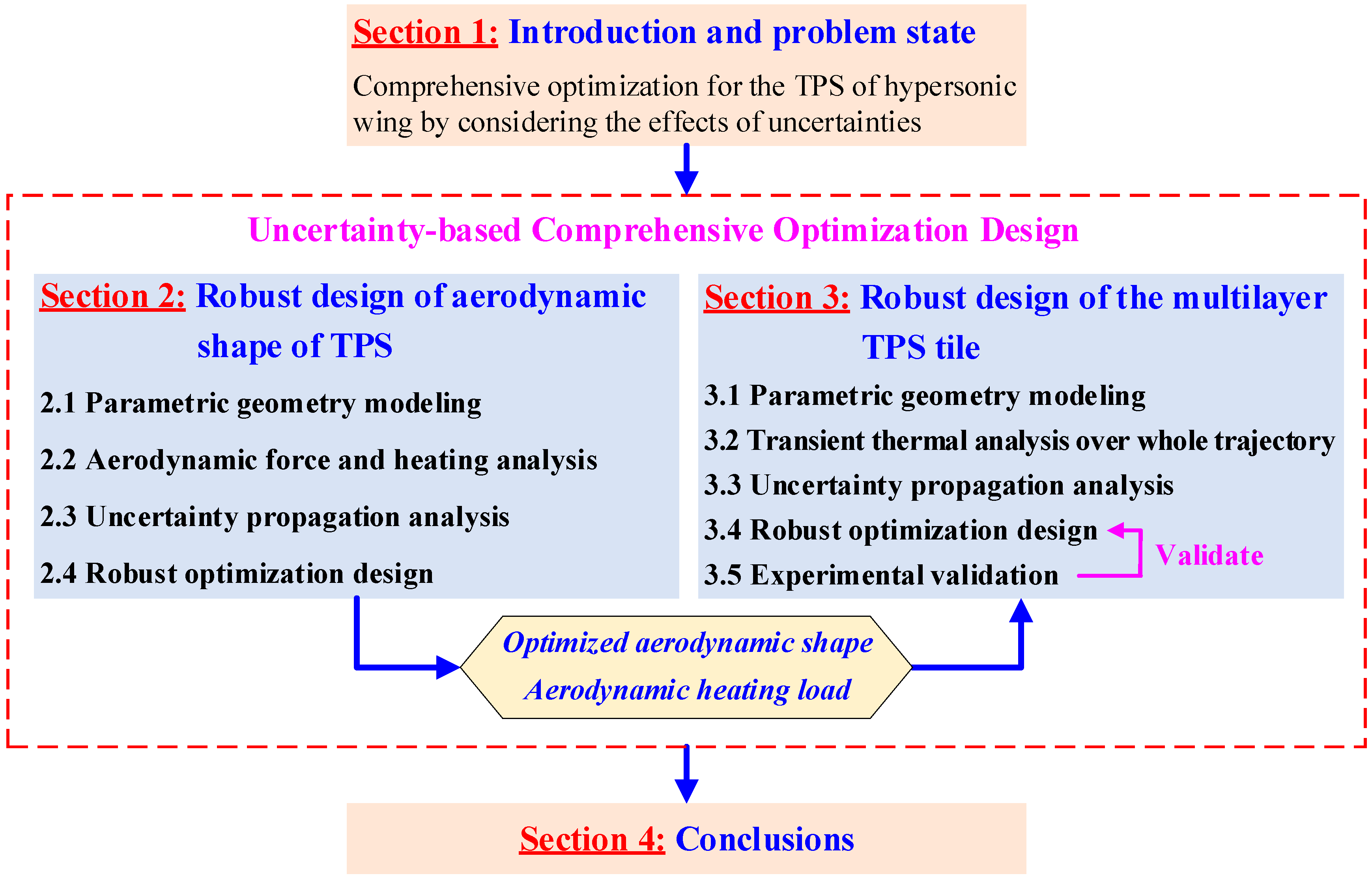
In view of the above-mentioned problems, this paper focuses on the comprehensive optimization design for the TPS of a hypersonic wing by carefully considering the effects of multi-source uncertain-but-bounded parameters. The whole frame of the work is illustrated in
Figure 1. In
Section 2, the robust optimization design for the aerodynamic shape of the hypersonic wing is conducted. The parametric geometry modeling, aerodynamic analysis, uncertainty propagation analysis and robust design are involved. In
Section 3, based on the optimized aerodynamic shape and aerodynamic heating environment, the robust optimization design for the multilayer TPS tile of the hypersonic wing is carried out. Furthermore, the proposed optimization method is validated by the thermal insulation experiment. Finally, this paper closes with some concluding remarks in
Section 4.
2. Robust Optimization Design for the Aerodynamic Shape of Hypersonic Vehicle
2.1. Parametric Geometry Modeling of the Aerodynamic Shape
The parametric geometry modeling is the fundamental step for the optimization design of the aerodynamic shape. As shown in
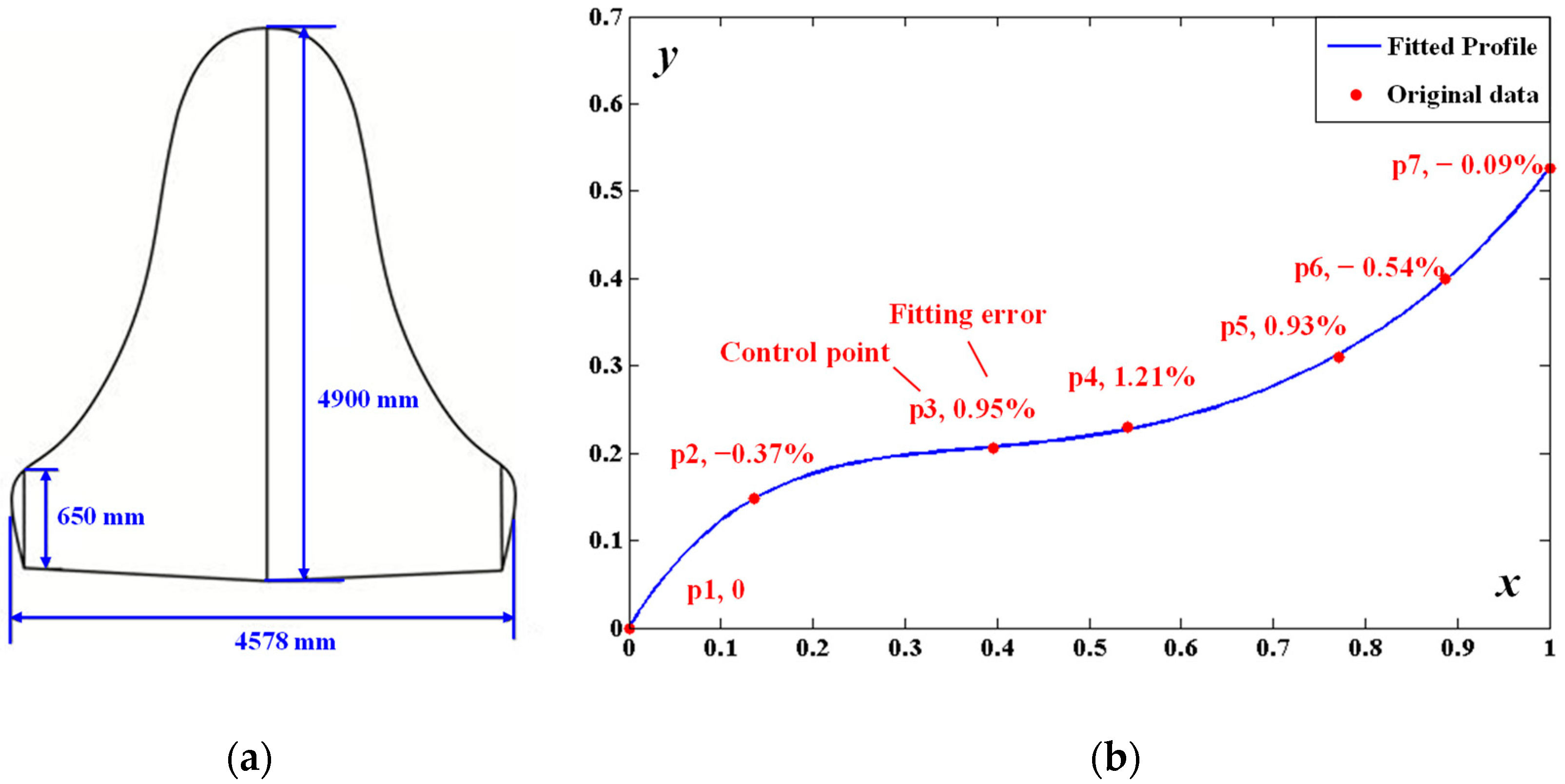
Figure 2a, an S-shape strake wing is adopted in the X-37B-like hypersonic vehicle. The wing profile can be fitted by a polynomial. Based on the original control points
on the leading edge of the wing, the polynomial can be expressed as:
where
is the fitted profile,
is the polynomial coefficient.
Here, 7 control points are chosen and the 5th-order polynomial is utilized. As a result, the fitted profile is shown in
Figure 2b. It can be seen that the wing profile is well fitted, as the maximum fitting error on the control points is less than 1.5%.
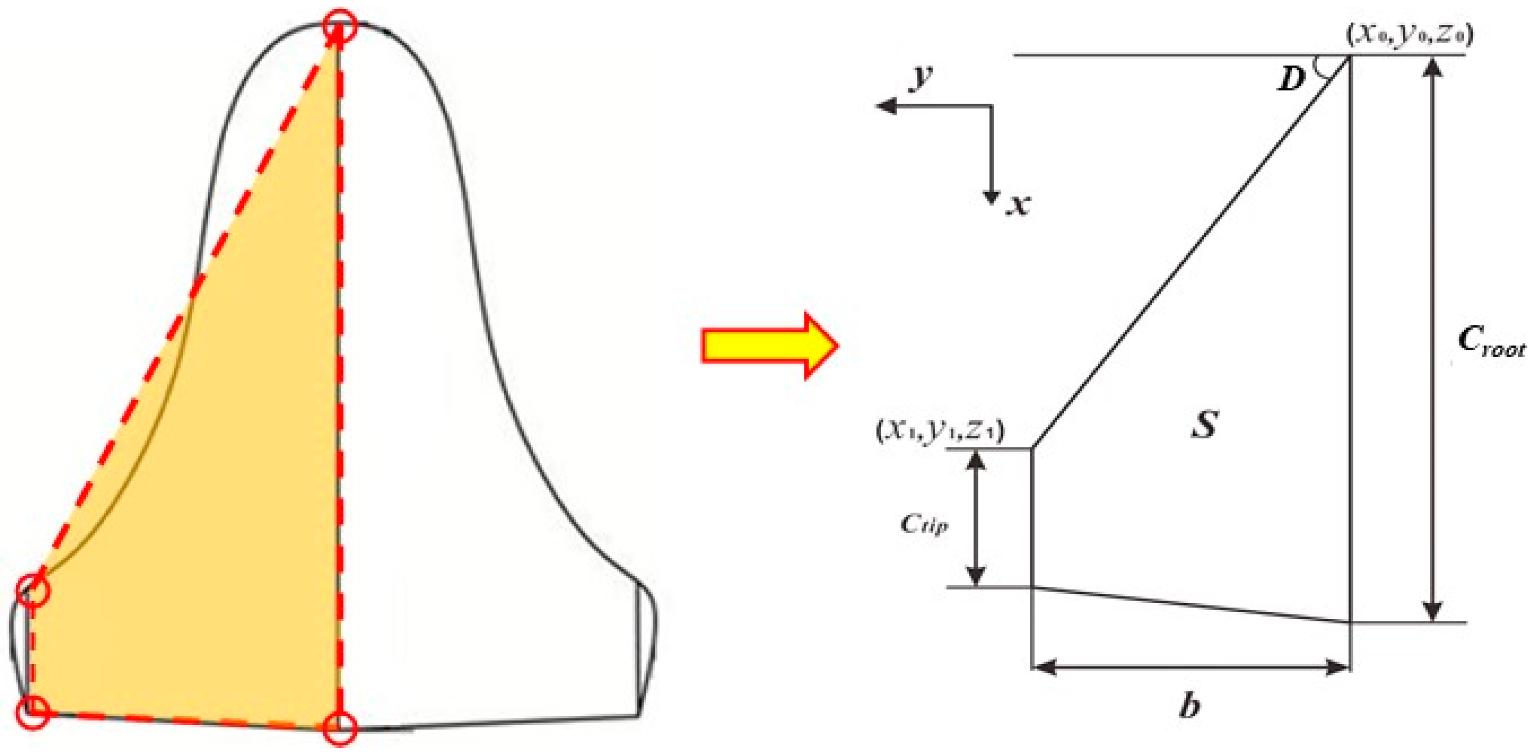
Further, to describe the wing profile more clearly, the fitted S-shape strake wing is equivalently simplified into the traditional trapezoidal wing (see
Figure 3). The aerodynamic shape can then be determined by several independent parameters, including wing reference area
, span-chord ratio
, taper ratio
, leading edge radius
, dihedral
and coordinates of the leading edge of the wing root
. The other parameters can be expressed as follows:
- (1)
Half-length of the wing
:
- (2)
Chord length of the wing root
:
- (3)
Chord length of the wing tip
:
- (4)
Coordinates of leading edge of the wing tip
:
After that, the aerodynamic shape of the hypersonic wing can be determined with the above parameters by utilizing three-dimensional geometry modeling technology.
Figure 4 gives the three-dimensional aerodynamic shape of the hypersonic vehicle with the parametric wing, where the initial values of the parameters are listed in
Table 1.
2.2. Aerodynamic Force and Heating Analysis of the Hypersonic Wing
To guarantee the efficiency in the optimization design, the engineering methods are applied in this work to calculate the aerodynamic force and heating of the hypersonic wing. Firstly, for the aerodynamic force, the tangent wedge method and the modified Dahlem-Buck method are utilized to compute the windward and leeside surface pressure of the hypersonic wing, in accordance with the Moore principle [
27]. The pressure coefficient
and
of the windward and leeside surface of a wing can be determined as follows [
28,
29]:
where
is the Mach number of the free-stream,
is the specific heat ratio,
and
are Mach number functions, while
,
,
are defined in ref. [
30].
For the aerodynamic heat, the leading edge of the wing is regarded as a cylinder with an inclined angle. The two-dimension approximation method based on the three-dimension Fay-Riddell method can then be used to calculate the heat flux at the stagnation point of the hypersonic wing.
The Fay-Riddell method [
31] is utilized to estimate the aerodynamic heatflux at the three-dimension stagnation point, with the radius of the curvature of the cylinder edges as:
where
,
and
represent the viscosity, density and enthalpy on the wall,
,
and
are the corresponding coefficients at the edge of boundary layer,
denotes the formation enthalpy,
is the velocity gradient.
The aerodynamic heat flux at the two-dimension stagnation point of the hypersonic wing can then be approximated as [
30,
32]:
where
denotes the three-dimension effect factor,
and
are the maximum and minimum radius of the curvature around the stagnation point.
Furthermore, the aerodynamic heating on the downstream region of the stagnation point can be calculated by the plate heat flow method, while that of the transition region is obtained by the empirical hemispheric heat flow method.
In this work, the flight attack angle of the hypersonic wing is 40°. The other flight conditions, including the flight altitude and velocity, are shown in
Figure 5. The results show that the harshest aerodynamic heating appears around 600 s, and at this moment the heat flux on the stagnation point rises to 265.6 kW/m
2.
2.3. Uncertainty Propagation Alysis of Aerodynamic Force and Heating
In this section, the uncertainty propagation analysis of the aerodynamic force and heating for the hypersonic wing are conducted. It is well acknowledged that various types of uncertainties are involved in the aerodynamic properties of the hypersonic vehicle. Therefore, the independent uncertainties are supposed to be determined first. In the work, the flight attitude , flight speed , and flight angle of attack are served as uncertain-but-bounded parameters, while the other parameters are assumed to be constant. Meanwhile, the heat flux on the stagnation point of the wing’s leading edge , as well as the lift-drag ratio , are selected to be the output responses.
Over the past years, several methods, including the first order interval Taylor expansion method [
33], the interval vertex method [
34], the iterative dimension-wise method [
35], the direct optimization method [
36], etc., have been developed to deal with the interval uncertainty propagation analysis. Although the interval vertex method, the iterative dimension-wise method, and the direct optimization method can obtain more accurate interval responses than the Taylor expansion method for situations where the strong nonlinear systems or wide range interval parameters are involved, the calculation amount would exponentially increase with the number of uncertain parameters. The calculation amount is not bearable when those three uncertainty propagation analysis methods are incorporated into the optimization design. In contrast, the interval Taylor series expansion method is an approximation method that possesses high efficiency. Zheng and Qiu [
32] have proved that this method is a good choice to accomplish the uncertainty propagation analysis of aerodynamic force and heating with high efficiency and accuracy. Therefore, in this paper, the first order Taylor expansion algorithm is adopted to acquire the upper and lower bounds of the output responses, as follows:
where overline and underline denote the upper and lower responses, superscript
and
denote the median and interval radius of the uncertain-but-bound parameters.
To solve Equations (10) and (11), the central difference method is utilized to calculate the first order derivative of the output responses versus the uncertain parameters as:
Here, the first order Taylor expansion algorithm-based uncertainty propagation analysis is conducted by the design of experiments method (DOE). The design matrix of DOE, as well as the aerodynamic responses, are listed in
Table 2. The deviation ratio of each parameter is chosen as 0.001%. According to Equations (10)–(13), the uncertain responses can then be calculated as
,
.
2.4. Robust Optimization Design of the Aerodynamic Shape
To alleviate the effect of the uncertainties on the aerodynamic force and heating, the robust optimization design of the hypersonic wing is conducted in this section. For comparison, two optimization design models, namely the traditional deterministic optimization model and the robust optimization model, are proposed.
(1) The deterministic optimization is to minimize the heat flux on the stagnation point by designing the geometry parameters, while satisfying the constraint that the lift-drag ratio of the optimized aerodynamic shape the does not decrease compared with the initial aerodynamic shape. The mathematical expression of the deterministic optimization model can be written as:
where
is the lift-drag ratio of the initial aerodynamic shape.
(2) The robust optimization is to minimize the amplitude and fluctuation of the heat flux on the stagnation point by designing the geometry parameters, while satisfying the constraint that the amplitude and fluctuation of lift-drag ratio of the optimized aerodynamic shape are not inferior to those of the initial aerodynamic shape. The mathematical expression of the robust optimization model can be written as:
where the deviation factor, defined as the ratio of interval radius to interval medium, is introduced to characterize the fluctuation degree. In addition,
and
are the deviation factors of the heat flux on the stagnation point and lift-drag ratio, and
is the deviation factor of the lift-drag ratio for the initial aerodynamic shape.
In order to avoid the local optimal solution, the global exploratory techniques are utilized to solve the optimization models. One the one hand, the Multi-Island Genetic Algorithm (Multi-Island GA) is utilized to solve the deterministic optimization model. The Multi-Island GA is essentially an improvement of the traditional GA. It has better global solving ability and computational efficiency than traditional genetic algorithms. The main feature that distinguishes it from traditional GA is the fact that each population of individuals is divided into several sub-populations called “islands”. All traditional genetic operations are performed separately on each sub-population. Some individuals are then selected from each island and are migrated to different islands periodically. In this way, the diversity of the population can be maintained, and a local optimal solution can be avoided as much as possible, in order to inhibit the phenomenon of premature maturity [
37]. On the other hand, the Non-dominated Sorting Genetic Algorithm (NSGA-II) is adopted to deal with the robust optimization model with multiple objectives. NSGA-II is an improved genetic algorithm characterized by fast nondominated sorting, which significantly reduces the time complexity compared with the conventional optimization algorithm [
38].
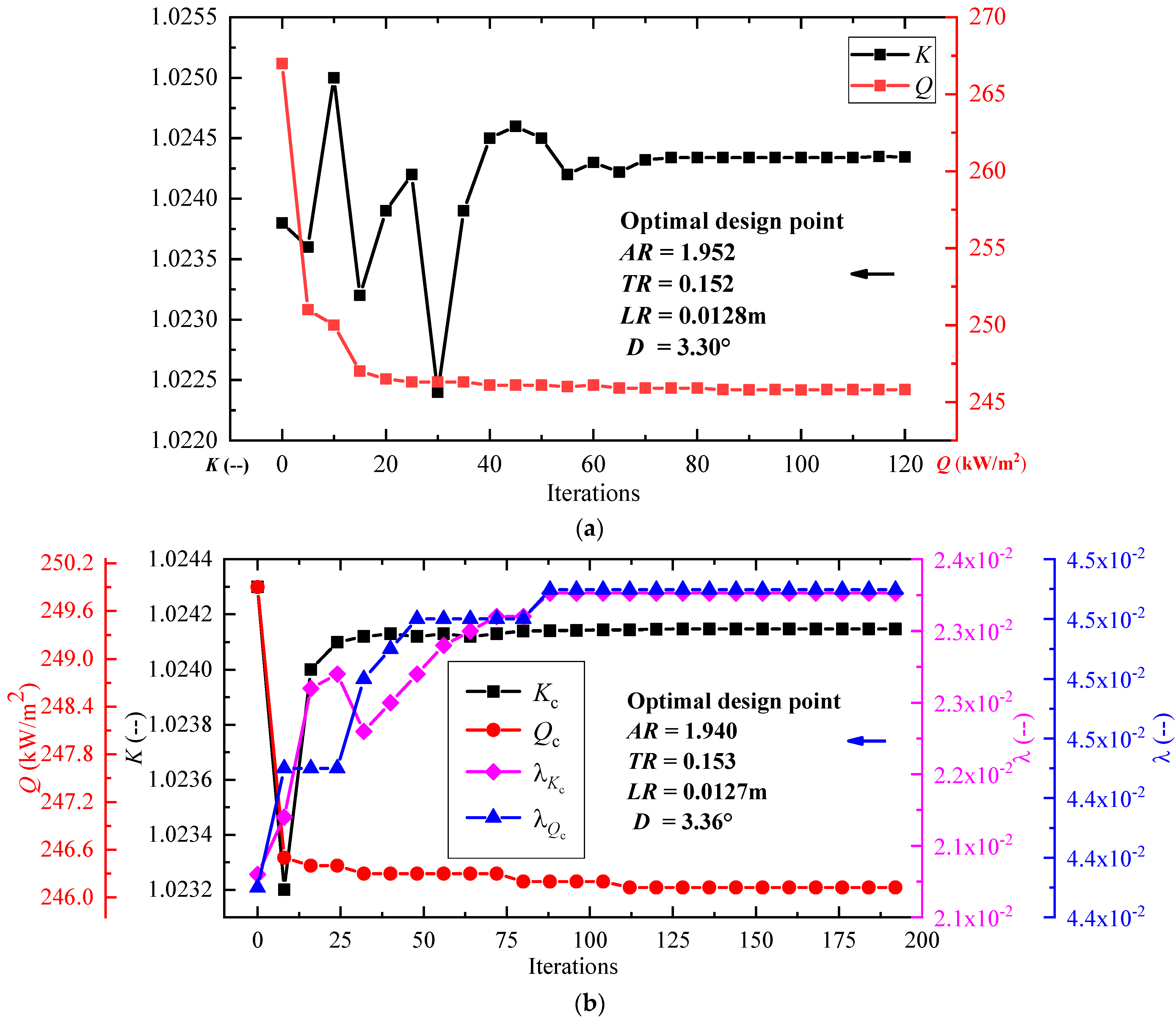
Figure 6a,b shows the optimization processes of the deterministic optimization design (DOD) and the robust optimization design (ROD). The fluctuations of both the design variables and output responses gradually decrease, and then the optimization model approaches to the optimal solution. For comparison, the results of the three aerodynamic shapes, namely the initial design, the deterministic optimization design, and the robust optimization design are listed in
Table 3. We can see that:
(1) In contrast with the initial design, the heatfluxes on the stagnation point efficiently decrease by 7.45% and 7.32% in DOD and ROD, respectively.
(2) Compared with the initial design, the fluctuation of lift-to-drag ratio increases from 0.0239 to 0.0247 in DOD, which means that the robustness of DOD is worse than the initial design, although the heat flux on the stagnation point decreases. The reason is that the influences of uncertainties are ignored in DOD, and thus the robustness cannot be guaranteed.
(3) Compared with the initial design, the fluctuation of the lift-to-drag ratio decreases from 0.0239 to 0.0233 in ROD by considering the robust constraint in the optimization model. Moreover, compared with traditional DOD, the heat flux on the stagnation point with a slight increase of 0.13% (DOD: 245.80 kW/m2, ROD: 246.13 kW/m2), but the fluctuation of lift-to-drag ratio increases by 5.7% (DOD: 0.0247, ROD: 0.0233). Consequently, it can be concluded that the proposed robust optimization method is superior to the traditional deterministic optimization by simultaneously decreasing the target value and enhancing the robustness of the output responses.
3. Uncertainty-Based Optimization Design for the Multilayer TPS of Hypersonic Wing
In this section, to effectively protect the hypersonic vehicle from extremely harsh aerodynamic heating during atmospheric entry/reentry, the size optimization of the TPS is conducted based on the optimized aerodynamic shape of the hypersonic wing in the above section. Considering the inherent uncertainties in the TPS, the robust optimization design method is proposed to accomplish the design, and the method is further validated by the heat insulation performance test of a typical TPS tile.
3.1. Parametric Modeling of the Multilayer TPS
As shown in
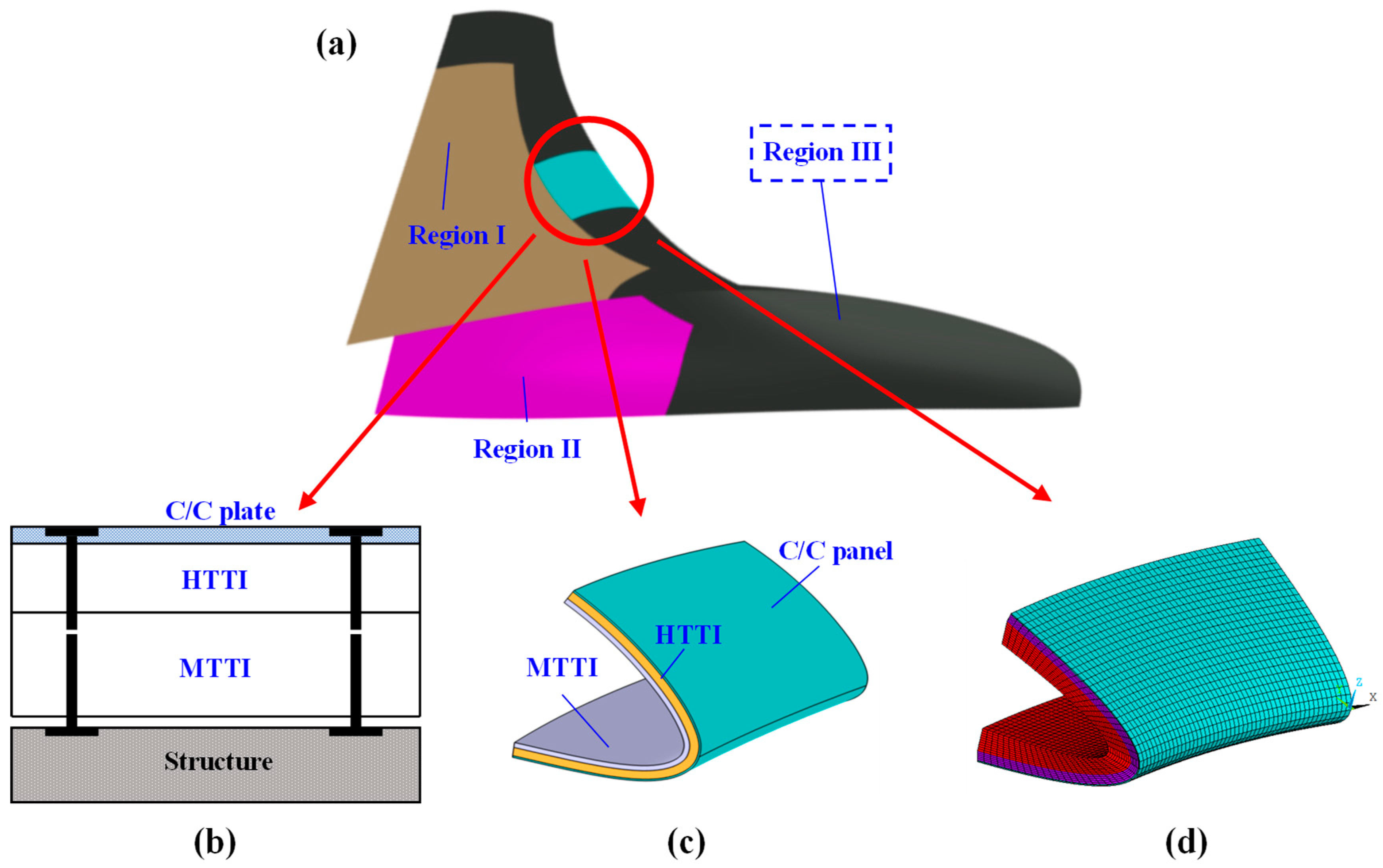
Figure 7a, the typical hypersonic wing can be generally divided into three regions according to the aerodynamic heating effects. Correspondingly, three types of materials are involved. Region I is the leeside area, where the aerodynamic heating is relatively weak; the Flexible Reusable Surface Insulation (FRSI) is adopted here. Region II is the windward area, where the aerodynamic heating is relatively drastic; the Ceramic Matrix Composite (CMC) tile is adopted here. Region III is the leading-edge area, which suffers from the most severe aerodynamic heating; the multilayer TPS is adopted here [
1].
Figure 7b describes the internal structure of the multilayer TPS, which is composed of a heat-resisting C/C panel, high temperature thermal insulation (HTTI) and middle temperature thermal insulation (MTTI).
Note that a huge mesh amount is needed when the TPS of the whole hypersonic wing is modeled. Under this circumstance, the cost of the computation is very high and even unaffordable for the uncertainty-based optimization design process. Therefore, some reasonable simplifications are made as follows:
- (1)
Only the multilayer TPS is chosen for the optimization design. One reason is that Region III takes up most of the mass compared with region I and Region II; thus, Region III possesses a greater potential for the lightweight design. Another reason is that the design space of the multilayer TPS is bigger than that of either CMC or FRSI, which is a simple single-layered structure.
- (2)
To avoid the stress concentration problem caused by the thermal deformation, the multilayer TPS is always paved as individual tiles. Flexible insulation material is filled in the gaps between the different multilayer TPS tiles, to prevent the transverse heat conduction and maintain the aerodynamics. In this case, it is rational to take one typical multilayer TPS tile for the analysis and optimization design.
Then, the finite element analysis (FEA) parametric modeling of the typical multilayer tile is further conducted. Here, the geometry driven FEA parametric modeling method is adopted. Firstly, as shown in
Figure 7c, the geometry of the multilayer tile is parametrically constructed based on the optimized aerodynamic shape in
Section 3, and the thickness of each layer is chosen as the independent geometry variable. The initial thicknesses of the C/C panel, HTTI and MTTI are 2 mm, 20 mm and 30 mm, respectively. Then, as shown in
Figure 7d, by utilizing the APDL language in ANSYS product, the FEA model is automatically constructed based on the parametrical geometry. This includes mesh generation, boundary condition definition, material assignment, and so on. Specially, in the parametric FEA model, the material properties (density, conductivity, specific heat) of each layer are selected as the independent variables. The nominal values of the material properties for the multilayer TPS are listed in
Table 4.
3.2. Transient Heat Transfer Analysis of the Multilayer TPS over Whole Trajectory
Based on the FEA model, the transient heat transfer simulation of the multilayer TPS tile over the whole trajectory is conducted to internal heat transfer characteristics. For the heat loads, the heat flux in
Figure 5 is imposed on the C/C panel over the trajectory. Meanwhile, the heat radiation is also applied on the C/C panel with an emissivity of 0.8. The other surfaces are set to be adiabatic.
Based on the law of Fourier heat conduction and energy conversation, the general governing equations of the transient structural heat transfer can be expressed as:
where
is the time,
is the structural temperature,
is the structural density,
is the structural specific heat,
is the structural thermal conductivity,
is the volumetric heating source in a solid, and
is the heat flux imposed on the boundary.
Moreover, the outer surface of the C/C panel is set as the second type of thermal boundary condition, and the surface heat radiation effect is considered as follows:
where
,
,
and
are aerodynamic heat flux, surface emissivity, surface temperature and ambient temperature, respectively;
denotes the Stefan–Boltzmann constant, whose value is 5.67 × 10
−8 W/(m
2∙K
4).
In this study, the finite element method is used to discretize Equation (16), and the numerical solutions for the nonlinear equilibrium equations have been carried out with the general finite element solver ANSYS Mechanical APDL Version 2022R1. The computational grid is a structured grid generated by ANSYS Mechanical, the analysis element type is set to be SOLID 70, and the mesh number is 160,000.
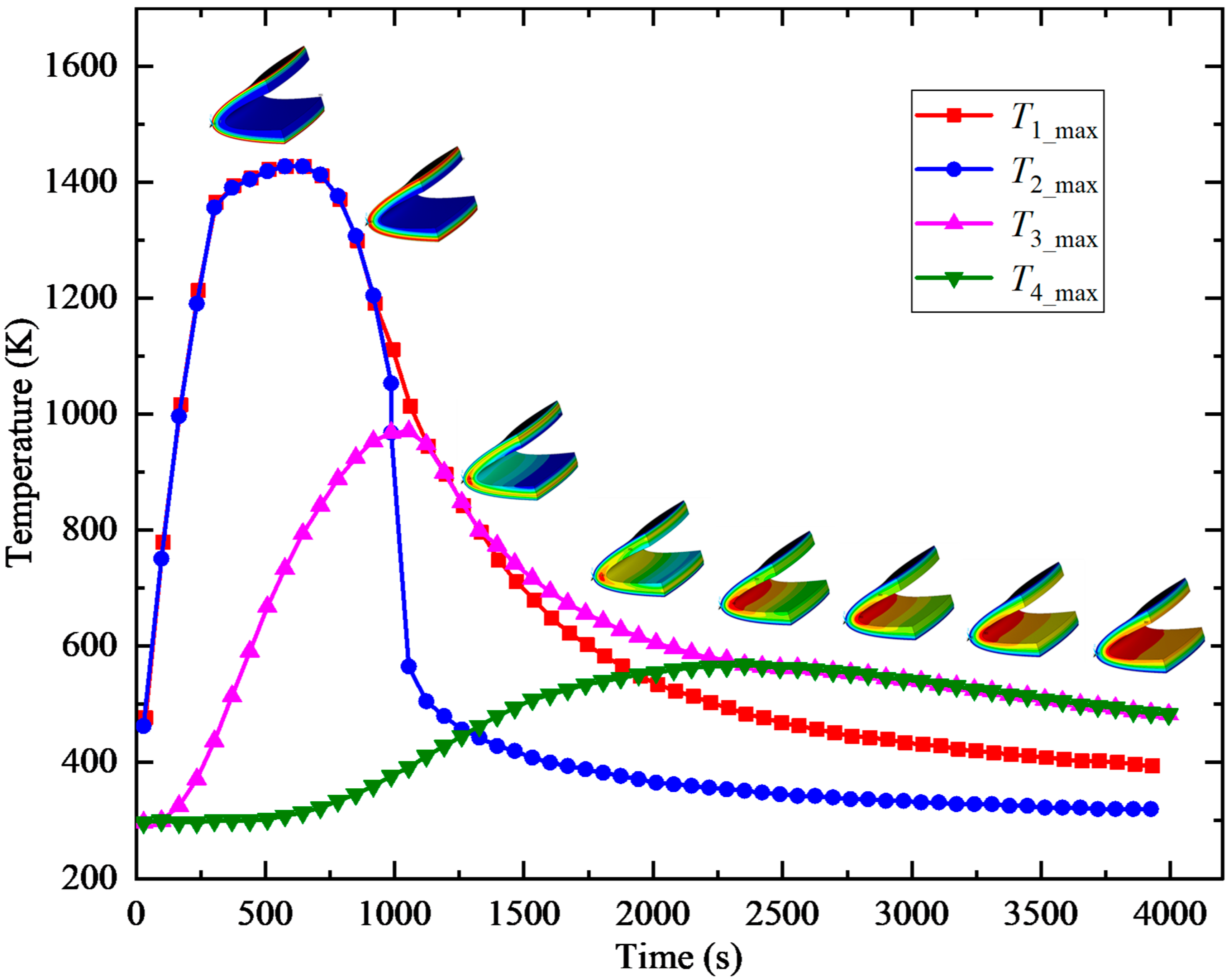
The calculated maximum temperature evolution of each layer and the inner surface are shown in
Figure 8, where
,
,
and
represent the maximum temperature of the C/C panel, HTTI, MTTI and the inner surface, respectively. It can be found that:
(1) The internal heat transfer characteristics of each layer are different due to the differences of the material properties. For example, the maximum temperature of the C/C panel rises much faster than that of either HTTI or MTTI for the higher heat conductivity.
(2) As the effects of aerodynamic heating gradually recede over the trajectory, the input heat through the outer surface of the C/C panel is less than the conducted heat inside material, thus the high temperature area is gradually moved inward from the C/C panel to MTTI, as shown in the temperature nephograms in
Figure 8.
(3) After 1000 s (the end time of the trajectory), though the aerodynamic heating stops, the heat stored in the material continues conducting to the interior. Therefore, the maximum temperature on the inner surface keeps increasing and reaches the peak around 2500 s, which means at least an extra 1500 s analysis time is required to obtain the reasonable results after the trajectory ends.
3.3. Uncertainty Analysis for the Transient Heat Transfer of the Multilayer TPS
Based on the established deterministic transient heat transfer analysis model, the uncertainty analysis of the multilayer TPS is further conducted. In the work, the material thermophysical properties, including heat conductivity , specific heat , and emissivity are served as uncertain-but-bounded parameters with the deviation factor of 0.05, while the other parameters are assumed to be constant. Meanwhile, , , and are selected to be the output responses.
Considering that the nesting of the uncertainty analysis and transient heat transfer analysis over the whole trajectory would lead to an unaffordable computational amount, an efficient uncertainty analysis method based on the surrogate model is proposed.
(1) Firstly, we take the design variables and uncertain parameters as design factors, and utilize the Latin Hypercube sampling method to obtain the design matrix. To guarantee the accuracy of the surrogate model, 500 sample points are calculated as source data, and another 50 sample points are calculated to conduct the error test.
(2) Then, to choose the approximate surrogate model, the Response surface model (RSM), Radial basis function (RBF), Orthogonal polynomial model (OPM), and Kriging model (KM) are compared. The R-square errors of all the surrogate models are listed in
Table 5. We can clearly see that the RBF model possesses the highest approximation quality. Therefore, the RBF model is chosen for the later uncertainty analysis and optimization design.
(3) After that, by taking advantage of the high computational efficiency of the RBF surrogate model, the uncertainty propagation analysis of the heat transfer characteristics for the multilayer TPS is conducted by utilizing the Monte Carol Simulation (MCS). Then, the uncertain responses can be easily calculated as , , , .
3.4. Robust Optimization Design for the Multilayer TPS
The uncertainty-based optimization design of the multilayer TPS tiles is conducted to alleviate the effect of the uncertainties in this section. The robust optimization method proposed in
Section 3 is employed here. The goal of the robust optimization is to reduce the weight of the multilayer TPS by designing the geometry parameters, while satisfying the constraints so that the upper values of the maximum temperature of each layer and the inner surface does not exceed the corresponding allowable value. In the meantime, the fluctuations of the four maximum temperature responses are not inferior to those of the initial TPS structure. The mathematical expression of the robust optimization model can be written as:
where
,
,
are the thicknesses of the C/C panel, HTTI, and MTTI, respectively.
is the mass of the multilayer TPS.
,
,
and
are the maximum allowable temperatures of the C/C panel, HTTI, MTTI and the inner surface, respectively. The values of
,
,
and
are set to be 1400 K, 1400 K, 800 K and 473 K. Moreover, the allowable deviation factors for each output response, namely
,
,
,
are calculated from the obtained uncertainty analysis results, and the values are 0.0145, 0.0159, 0.1056, 0.0585, respectively.
Specially, some rational simplifications are made for the above optimization model to improve the optimization efficiency.
(1) As the initial thickness of the C/C panel is only 2 mm, the design space of is very small, and further thinning of the panel would decrease the load bearing capacity. Therefore, remains constant as the initial value during the optimization process.
(2) Owning to the thin thickness and high conductivity of the C/C panel, the aerodynamic heat would be quickly conducted to HTTI. Therefore, the maximum temperatures of the C/C panel and HTTI are nearly the same, and are highly dependent on the aerodynamic heating state, rather than the thicknesses of HTTI and MTTI. Thus, only the constraints of MTTI and the inner surface are considered in this work.
Consequently, the robust optimization model in Equation (18) can be simplified as:
Here, the global optimization technique, that is the Multi-Island GA is utilized to solve the above optimization model.
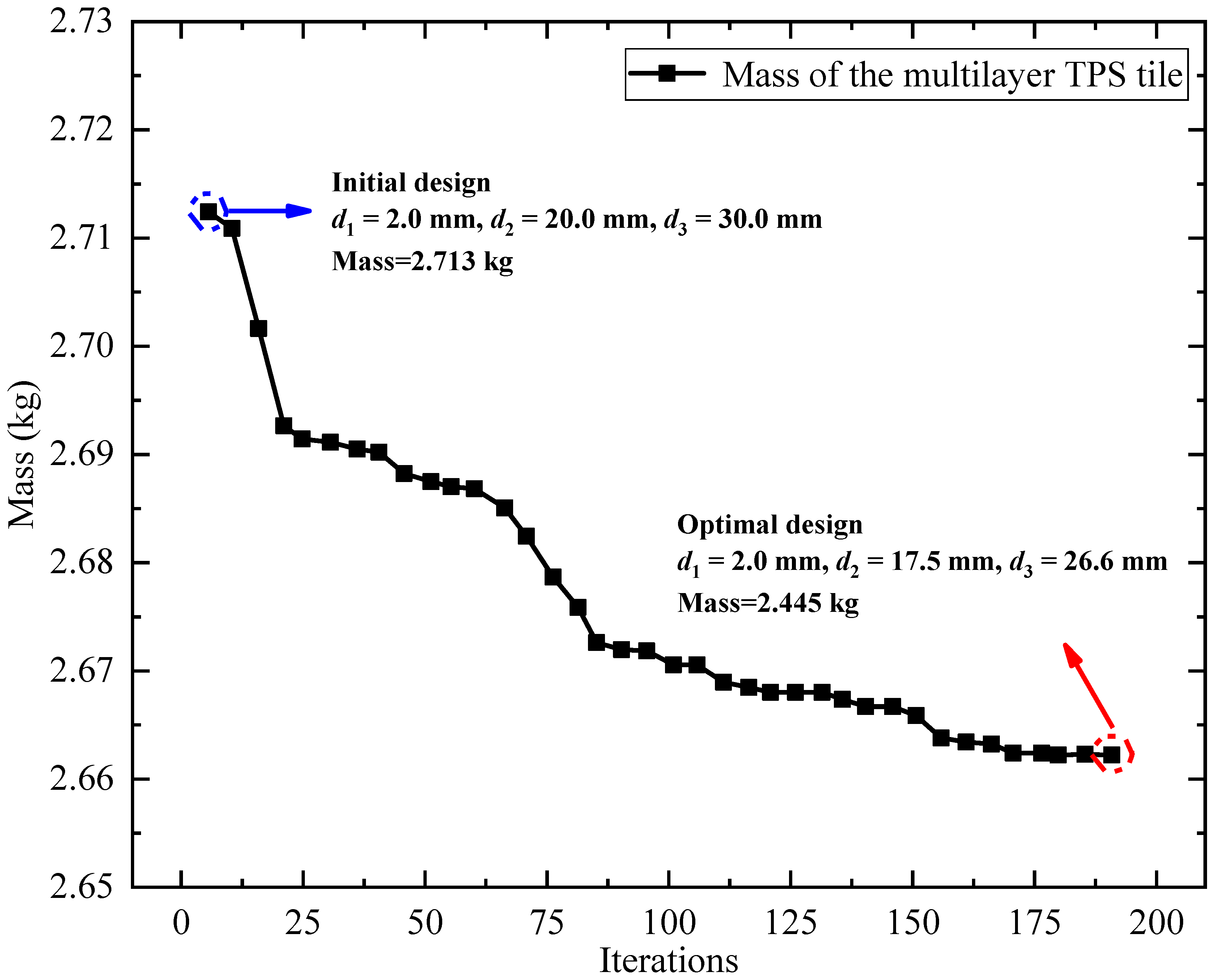
Figure 9 shows the optimization process of the robust optimization design. The optimized results are
,
, and the mass of the multilayer TPS is reduced from 2.713 kg to 2.445 kg by 9.89%. In the meantime, for the optimized design,
,
, which satisfies the allowable temperature requirements. Moreover, the deviation factors of the uncertain responses are
,
, which means the robustness of maximum temperature of MTTI and the inner surface are ensured. Therefore, it can be concluded that the proposed uncertainty-based optimization method can efficiently reduce the mass of the TPS of the hypersonic wing on the premise of guaranteeing the heat-insulating performance.
3.5. Experimental Validation for the Uncertainty-Based Optimization Design Method
3.5.1. Experimental Setup
To validate the proposed uncertainty-based optimization design method, the thermal insulation performance experimental tests were conducted. As shown in
Figure 10a, the typical thermal protection tile used in the experiment was made of five layers, including the C/C panel, the flexible insulation material (FIM), MTTI, and the strain isolation pad (SIP). The panel size was 200 mm × 200 mm, and the thicknesses of each layer from outer to inner were 4 mm, 3 mm, 20 mm, 31 mm, 3 mm, respectively.
Figure 10b described the schematic diagram of the thermal insulation performance test. The test piece was vertically fixed inside the square frame made of high-temperature ceramics. The outer surface of the test piece faced the quartz heat lamp, which can simulate the aerodynamic heating environment after power up. Meanwhile, to obtain the temperature responses, the high temperature thermocouples were carefully placed on the outer and inner surfaces. The flexible insulation plate was placed 20 mm away from the inner surface to prevent heat loss.
In the test, the temperature control method was utilized to determine the heating intensity. Considering the power limit of the quartz heat lamp, the controlled temperature was set to 1200 K. The control process could be implemented by following steps. Firstly, the instantaneous temperature on the outer surface was measured and fed back to the control system. Then, the control system compared the measurable temperature and the controlled temperature to acquire the control error. After that, the power of the quartz heat lamp could be timely adjusted based on the control error to obtain the controlled temperature.
3.5.2. Experimental Verification
In this work, the thermal insulation testes of two thermal protection tiles are conducted to verify the established uncertainty-based optimization procedure.
Firstly, the test of the initial thermal tile was utilized to demonstrate the uncertainty analysis method. As illustrated in
Figure 11a, the uncertain response of
can be calculated as
K based on the uncertainty analysis method proposed in
Section 3.3. Meanwhile, the measured maximum temperature of the inner surface
was 347.15 K. Apparently, the experimental results belonged to the uncertain responses obtained through the uncertainty analysis method, which validated the effectiveness of the proposed method.
Then, the proposed robust optimization model was utilized to optimize the thermal protection tile. Considering that the design spaces for thicknesses of the C/C panel, FIM and SIP were rather small, only the thicknesses of HTTI and MTTI were considered as the design variables. The objective and constraints were the same as the optimization model proposed in
Section 3.4. The optimization model was solved by the Multi-Island GA, and the optimized results were
,
. The thermal protection tile was fabricated based on the optimized geometric parameters, and the mass decreased from 2.691 kg to 2.537 kg by 5.72%. Later, the heat insulation test was conducted for the optimized tile. As illustrated in
Figure 11b, the uncertain response of
could be calculated as
K based on the uncertainty analysis method. Meanwhile, the measured maximum temperature of the inner surface
is 341.48 K. Clearly, the experimental results belonged to the uncertain responses obtained through the uncertainty analysis method, which validated the effectiveness of the proposed uncertainty-based optimization design method to a certain extent.
4. Conclusions
In this paper, the uncertainty-based comprehensive optimization design for the TPS of a hypersonic wing is carried out by sequentially performing the robust design of the aerodynamic shape and the multilayer TPS tile. Firstly, compared with the conventional deterministic optimization method, the proposed robust optimization method decreases the fluctuation of lift-to-drag ratio by 5.7%, with a small increase of heat flux on the stagnation point by 0.13%. Consequently, it can be concluded that the proposed optimization method is superior to the traditional method, by simultaneously decreasing the target value and enhancing the robustness of the output responses. After that, based on the optimized aerodynamic shape and the corresponding aerodynamic heating loads, the uncertainty-based optimization design of the multilayer TPS tile is conducted. The results show that the mass of the TPS tile efficiently decreased from 2.713 kg to 2.445 kg by 9.89%, and the robustness of the optimized design is better than the initial design. Moreover, the proposed robust optimization method is validated through the heat insulting experiment of the typical multilayer TPS tile. Therefore, it can be concluded that the proposed optimization method can efficiently reduce the mass of the TPS, on the premise of guaranteeing the robustness of the heat-insulating performance.
