Abstract
This study was focused on the stability analysis of the self-propelled radish harvester. A 3D simulation model was developed using RecurDyn and used to analyze the rollover angle. The rollover angle of the original radish harvester was analyzed and checked to see if it satisfied the standard overturning angle (i.e., 30°). To improve it, three simulated weights (50, 100, and 150 kg) were added to three positions (front, center, and rear). The rollover angle of the radish harvester was slightly less than the criterion angle at a deflection angle of 180°. This issue was solved by attaching an additional weight to the front with a deflection angle of 180 degrees. In particular, when an additional weight of 50 kg was attached to the front or an additional weight of 150 kg was attached to the center or rear, the criterion angle range satisfied all conditions. In conclusion, it is feasible that the self-propelled radish harvester prototype could satisfy the criterion angle with the additional load and could be applied to field agriculture.
1. Introduction
In Korea, radish is the third-largest vegetable crop [1] and is used as a typical side dish with the traditional Korean food kimchi. Korean radish kimchi has six categories: kkakttugi, seokbakji (or nabakkimchi), dongchimi, jjanji, jangachi, and jangkwa [2]. Generally, vegetables are classified according to the parts used and their function into six types: flavor, root, leaf, stem, fruit, and western vegetables. Among them, flavor vegetables cover almost 44.9% of the cultivation area [3], which has been decreasing at an average rate of around 0.8% per year. According to Korean statistics, radish cultivation is decreasing day by day. The growing area dropped by 12.3% from 2018 to 2019, almost 752 ha [4].
In addition, the number of farmers decreased by 22% from 2,962,000 in 2011 to 2,317,000 in 2020 [5] in Korea. In particular, the proportion of farmers aged 65 and over increased by 26% from 33.7% in 2011 to 42.5% in 2020 [6,7]. The solution to the problem of aging farm labor could lie with machinery. In Korea, in 2020, almost all paddy fields were mechanized (98.6%), but the upland field mechanization rate was lower (61.9%) [8]. In particular, in case of the radish harvest, the mechanization rate in 2020 was very low (11.3%) [9]. To date, a machine for harvesting radish has not yet been made commercially available, yet mechanization is required to address the growing shortage of workforce and to minimize labor costs and time.
Radish is an upland field crop [1], and more than 90% of Korea’s upland fields have a slope of 2° or more, with 23% of all upland fields having a slope of 15° or more [10]. Generally, these fields are very uneven, and the slope affects the stability and performance of agricultural machinery [11]. Mashadi [12] reported that about 50% of all farm accidents occurred because of machinery instability including the rollover. According to Mayrhofer et al. [13], the stability of a machine fails when the slope angle is higher than the rollover angle, and they noted that the most frequent cause of death and injury from farm machinery accidents in Australia were caused by rollover. Similar findings were made by Majdan [14], who also pointed out a good understanding of slope stability is essential for safe and stable commercialized agricultural machinery. Song [15] stated that, in addition to serious injury and economic losses, rollover accidents create mental stress. Therefore, it is important to make agricultural machinery stable to avoid unwanted agricultural accidents. Various parameters of agricultural machinery affect stability, such as static, dynamic, and operational parameters. The static parameters include the wheelbase, the width, and the center of gravity (CoG) of the machine, while the operating parameters are considered among the dynamic parameters.
Some agricultural machinery (e.g., tractors) have a rollover protective structure (ROPS) [16,17,18], which according to Guzzomi et al. [19] is designed to avoid or minimize the risks to the driver in case of a rollover during field operation. They mentioned that the ROPS is characterized by having a large enough clearance space to protect the driver. Generally, rollovers occur under static or operational conditions in the lateral or longitudinal directions. Stability angles vary from 15 to 45° for different agricultural machinery according to ISO 16231-2 [20]. In Korea and Japan, the slope operation limit in stability evaluation is 15° to minimize overturning [21]. However, the stability angle also varies on the basis of the weight balance [22]. Song [23] found that the lateral load transfer ratio (LTR) is a main cause of machine instability. It was also mentioned that LTR has a high impact on the front wheel of the machine and causes longitudinal rollover accidents. Therefore, weight balance is another important aspect to consider when analyzing the stability or rollover angle in the manufacturing of a stable and safe machine.
There are many studies that have been conducted on the rollover angle analysis due to the stability of the machinery, especially agricultural machinery. This is because the agricultural field is highly uneven and has a sloppy field due to variable soil hardness levels due to stone, crop straw, vibration of the machine, and so on [24]. Chowdhory et al. [25] developed a 3D simulation model of a tractor-mounted radish collector and analyzed the overturning angles. They also determined the CoG and transverse overturning angles mathematically and evaluated the simulation results by indoor test. They found that the tractor-mounted radish collector could safely be performed at 30° sloppy field. Iqbal et al. [26] recently published their research on the automatic pepper transplanter. They developed the 3D simulation model pepper transplanter and theoretically analyzed both static and dynamic overturning. They stated that the transplanter overturned at 29.3° and 49° for uphill and downhill, respectively. The rollover index was developed for buses and estimated the lateral load transfer ratio (LTR) [27]. Moreover, they stated that this approach decreased the changes of rollover considering the road bank angle. Another study was conducted on the lateral stability of a narrow-track tractor [28]. In this study, a kinematic model was developed to calculate the lateral stability angle for the tractor. They reported that 39.3° was the lowest stability angle. Therefore, the rollover angle was studied in this study for the stability of the radish harvester, especially for upland sloppy fields.
This study was mainly focused on a stability analysis of the self-propelled radish harvester to identify the exact rollover slop angle on the basis of the CoG and operational safety, awareness, and comfort. The purpose of this study was to simulate a rollover of a self-propelled radish harvester prototype to derive an improvement plan. Finally, this study will recommend for the users the best conditions to perform the radish harvester with high stability, safety, and comfort. The specific objectives of the study were (a) to determine the lateral overturning angles according to the deflection and tilt angles using a 3D simulation model, (b) to validate the simulation results by indoor test, and (c) to improve the rollover angle by attaching and simulating three additional loads (50, 100, and 150 kg) at three positions (front, center, and rear).
2. Materials and Methods
2.1. Specifications of Radish Harvester
In this study, the self-propelled radish harvester (Hope Farming Instrument Co. Ltd., Naju, Korea) is shown in Figure 1. The dimensions (length × width × height) were 3500 × 2250 × 2000 mm, and total weight was 1350 kg. The harvester was equipped with a V-type air-cooled, two-cylinder four-stroke gasoline engine. The rated power of the engine was 18.6 kW with a rotational speed of 3600 rpm and normal working speed of 0.27 m/s. The specifications are shown in Table 1.
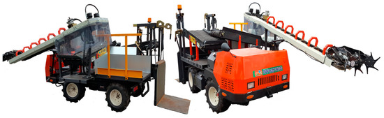
Figure 1.
The self-propelled radish harvester used in this study.

Table 1.
The specifications of the radish harvester used in this study.
2.2. Three-Dimensional (3D) Simulation Model of the Radish Harvester
The radish harvester consisted of five main systems: engine, drive unit, platform frame, pull-out harvester unit, and harvested radish conveyor. To develop the 3D simulation model, multi-body dynamic simulation software (RecurDyn V9R1, FunctionBay, Seongnam, Republic of Korea) capable of analyzing the stability of the radish harvester was used. The model was developed by reflecting the drawings and specifications of the main system, as shown in Figure 2. The CoG was determined through a simulation based on the drawings and harvester specifications. The simulation parameters of the 3D model for the radish harvester, including the CoG and moment of inertia, are listed in Table 2.
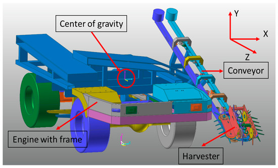
Figure 2.
The 3D model of the radish harvester used in this study.
Table 2.
The simulation parameters of the 3D model of the radish harvester used in this study.
2.3. Mathematical Model of the Radish Harvester Stability
The rollover of the self-propelled radish harvester was performed using a simulation program based on a mathematical model [29] involving two types of rollover angles in a stability evaluation. The first was the lateral overturning angle that occurs during a sharp turn or when the rear wheel is lifted due to driving along the contour line direction of the slope [30]. The second was the longitudinal overturning angle that occurs transverse to the slope direction line, but the field slope is the main cause of it [31].
The self-propelled radish harvester has an integrated frame and front axle. Thus, the front axle cannot swing separately, and suspension is not included. Although they may have a significant impact on the static and dynamic balance of the machine, they were not considered in this rollover test.
The lateral overturning angle for the rear wheel was determined using Equations (1) and (2), which were obtained from Figure 3.
where R1Z is the reaction force of the ground (N); is the lateral overturning angle (°) for the rear wheel; is the track (mm); is the wheelbase (mm); is the center of height; is the distance (mm) from the ground to A; is the distance (mm) from the center to rear-wheel contact point; and is the distance (mm) from the center to front wheel contact point.
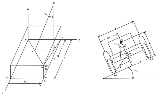
Figure 3.
The determination of the lateral overturning of the radish harvester.
The preliminary center of the radish harvester was G () at the line of AB. To obtain the overturning angle for the front wheel, the position of the CoG was newly assumed to be at the line BD. The front-wheel overturning angle () was determined using Equation (3) [29].
where is the lateral overturning angle (°) for the front wheel; is the coordinate of the CoG ; and is the coordinate of .
The XYZ coordinate was designed from the preliminary lateral overturning angle axis AB, which is shown in Figure 4. The and were determined from Equations (4) and (5), respectively.
where is the angle of change (°) from y-axis to Y-axis, and is the angle of change (°) from z-axis to Z-axis.
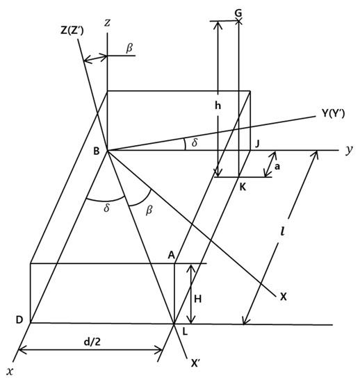
Figure 4.
Schematic diagram of the new coordinates for determining different angle changes between new axes.
To determine the center of gravity, the relation between xyz and XYZ coordinates are found in Equations (6)–(8) [29].
The relation between the center position of xyz (G ()) and XYZ coordinates are found in Equations (9)–(11), where the CoG is G(x,y,z).
For the rear-wheel lateral overturning angle, the CoG (G) at the line of AB was converted using to the CoG at XYZ coordinate using Equations (12)–(16).
The relation between both rotation angles of the CoG were obtained using Equations (17)–(22).
where is the rotation angle (°) of the CoG (G) with respect to the AB axis.
2.4. Rollover Test Condition
The rollover is the process of rolling over. The vehicle, which overturns laterally or longitudinally during the operations, occurs an accident. Bacicoa et al. [32] stated that the purpose of rollover is to improve the stability of the machine and ensure the safety of passengers from unwanted accidents. The rollover process of the self-propelled radish harvester was divided into lateral overturning (tilting to the left or right) and longitudinal overturning (tilting forward or backward). In general, such rollovers are affected by irregular soil conditions caused by obstacles such as stones, pebbles, and steep slopes [11,33]. A rollover angle test should consider the irregular soil surface conditions (i.e., upland field slope) in which a self-propelled radish harvester would operate. To consider both lateral overturning and longitudinal overturning for the rollover test of the self-propelled radish harvester, lateral overturning tests were performed according to the deflection angles of 0 and 180°. The lateral overturning tests were performed for measuring tilt angles of the radish harvester by moving upward the test jig by 1 degree up to 70 degrees with respect to the pivot point, as shown in Figure 5a, and the validation of the lateral overturning test using an indoor test bench at the Foundation of Agricultural Technology Commercialization and Transfer (FACT), Iksan, Korea. The test jig is the platform on which the harvester was set for the testing of tilt angles, as shown in Figure 5b. In addition, the transverse angles were calculated mathematically for the deflection angle range of 360° with 15° increments in the clockwise direction on the test jig. The rotation axis of the radish harvester for adjusting the deflection angle was selected as the horizontal and vertical central axes of the platform as shown in Figure 6.
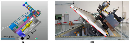
Figure 5.
The conditions of the rollover test for tilt angle: (a) simulation of the lateral overturning and (b) validation test of the lateral overturning of the radish harvester.
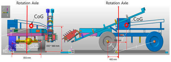
Figure 6.
The rotational axle of the self-propelled radish harvester for adjusting the deflection angle.
In the radish harvester, the weight distribution was concentrated on the left side because the weight distribution on the side where the conveyor belt of the harvester was located was larger. To improve the rollover issue by the abovementioned weight distribution, an additional load was installed on the opposite side of the conveyor belt of the harvester. The rollover angle was simulated and evaluated by installing three load conditions (50, 100, and 150 kg) to three location points, namely, the front, center, and rear of the radish harvester for weight distribution, which is shown in Figure 7. The Korea Foundation of Agri. Tech. Commercialization and Transfer (FACT) judges that at least the tilt angle of 30° or more was safe for the lateral angle of agricultural machinery [34]. Therefore, in this study, 30° was selected as the stability criterion for the rollover of the self-propelled radish harvester.
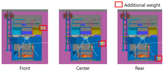
Figure 7.
The location of the additional weights installed in the self-propelled radish harvester at the front, center, and rear.
2.5. Analysis Method
In this study, several statistical approaches were used in this study to evaluate the rollover angles for both the simulation and measured experiments. The software used for the analysis was IBM SPSS Statistics (SPSS 25, SPSS Inc., New York, NY, USA). The error and accuracy of the tilt angle for various load conditions were analyzed for both simulation and experimental methods by regression methods. The coefficient of determination was also determined. The R-square value, which was over 0.90, was considered reliable for comparison between two variables [6]. The R-squared can be obtained by the following Equation (23):
where is the regression coefficients of the tilt angle for both methods; is the ith measured tilt angle (°); is the ith simulation tilt angle (°); and is the mean of the measured tilt angle (°).
3. Results and Discussion
3.1. Analysis of the Rollover Angle
Figure 8 shows the contact force according to rollover angles of the radish harvester during the first and second rollovers. The first and second rollover angles were observed when the deflection angle was 0°, as shown in Figure 8a. The first and second rollover angles occurred when the tilt angles were around 50.12 and 63.17°, respectively. It was observed when the contact force of the front left wheel decreased from around 8000 N at a tilt angle of 0° to 0 N at an angle of 50.12°. However, the contact force of the front right wheel sharply increased from approximately 4000 N to 20° of tilt angle, and then started to decrease and become 0 N at approximately 63.17°. In the case of the deflection angle 180° shown in Figure 8b, it was observed that the first and second rollover angles for both front and rear right wheels were the same, accounting for approximately 27–28°. For the front right wheel, the first rollover angle was observed when the contact force decreased from around 3000 N at a tilt angle of 0° to 0 N at 28°. For the rear right wheel, the first rollover angle was observed when the contact force decreased from around 2500 N at a tilt angle of 0° to 0 N at 27°. In the case of the second rollover angle for all wheels of the radish harvester, it was observed when both front and rear left wheels detached from the ground.
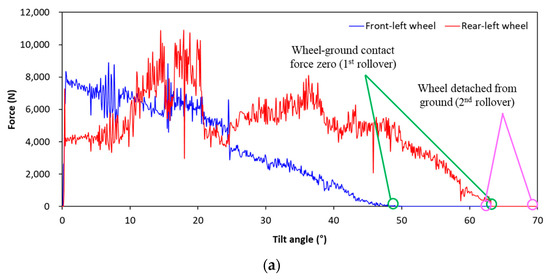
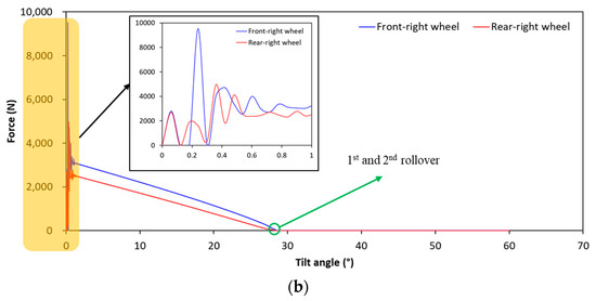
Figure 8.
The rollover angles and contact force of the radish harvester: (a) first and second rollover angles on the deflection angle of 0°, and (b) first and second rollover angles on the deflection angle of 180°.
3.2. Validation of the Rollover Angle
Figure 9 shows the verification of rollover angles of the radish harvester according to the deflection angles of 0 and 180°. To identify the similarity, accuracy, and error between the simulation and experimental rollover angles, the linear regression and values were calculated. It was observed that values of the first and second rollover angles for both deflection angles 0 and 180° were 0.911 and 0.9589, respectively. From the regression equations (y), it was clear that the simulation and experimental rollover angles were in a linear relationship with each other. The results indicate that both simulation and experimental rollover angles were a similar trend.
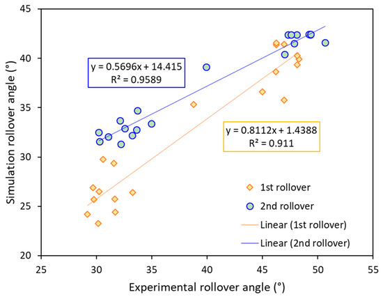
Figure 9.
The verification of the simulation of first and second rollover angles of the radish harvester for the defection angles of 0 and 180°.
According to the FACT, the standard overturning angle of the radish harvester should be not less than 30°. However, in the case of the deflection angle of 180°, the rollover angle of the radish harvester was slightly less than standard overturning angle. This suggests that when the radish harvester tilted with respect to the wheel on the side of the harvester conveyor belt, the rollover angle was found to be less than 30°, suggesting a risk to stability. Therefore, there is a need for an improvement plan.
3.3. Improvement of Rollover Angle for the Radish Harvester Considering Additional Weight
To solve the problem in the previous section, a weight (50, 100, 150 kg) was installed at three positions (front, center, and rear). The maximum rollover angles for the weights at the front were around 60.96, 60.83, and 59.92° at deflection angles of 45, 30, and 45° for 50, 100, and 150 kg, respectively. The minimum rollover angles were 31.71, 31.64, and 33.25° at deflection angles of 180° for 50, 100, and 150 kg, respectively. The results are shown in Figure 10a–c. Therefore, if an additional load of at least 50 kg or more is installed at the front, the rollover of a wider area than the standard overturning angle can be satisfied, and the rollover criterion for the radish harvester was met.
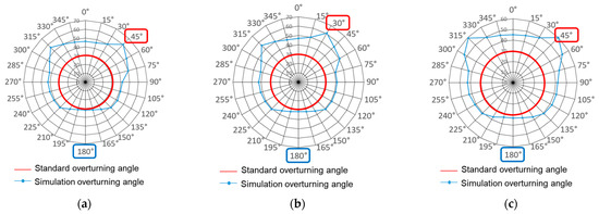
Figure 10.
The rollover angles for the attached weights at the front of the radish harvester: (a) 50 kg, (b) 100 kg, and (c) 150 kg.
In the case of the attached weights at the center of the radish harvester, the maximum rollover angles were approximately 61.04, 62.16, and 62.09° at a deflection angle of 45° for 50, 100, and 150 kg, respectively. For a deflection angle of 180°, the minimum longitudinal overturning angles were 29.19, 29.75, and 30.24° for 50, 100, and 150 kg, respectively. The results are shown in Figure 11a–c. Unlike the additional load arranged at the front, an additional load at the center must be at least 150 kg to satisfy the standard overturning angle.
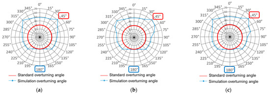
Figure 11.
The rollover angles for the attached weights at the center of the radish harvester: (a) 50 kg, (b) 100 kg, and (c) 150 kg.
Figure 12 shows the rollover angles when the weights were attached at the rear of the radish harvester. The maximum rollover angles at a deflection angle of 45° were 61.04, 62.16, and 62.09° for 50, 100, and 150 kg, respectively. For a deflection angle of 180°, the minimum rollover angles for 50, 100, and 150 kg were 29.19, 29.75, and 30.24°, respectively. When the additional load was placed at the rear, results were similar to those for loads placed at the center but different from those at the front. If an additional load is installed at the rear of the radish harvester, a weight of at least 150 kg must be used to satisfy the standard overturning angle.
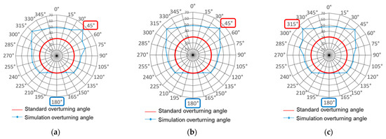
Figure 12.
The rollover angles for the attached weights at the rear of the radish harvester: (a) 50 kg, (b) 100 kg, and (c) 150 kg.
Table 3 shows the rollover angles for different additional weights on different positions of the radish harvester. In the range of 0 to 180°, it was observed that the rollover angle reached dramatically from 46.2° at the deflection angle of 0° to 63.28° at the deflection angle of 45°, then the tilt angle of the radish harvester sharply decreased until the deflection angle increased up to 180°. However, in the range of deflection angles of 180–315°, the rollover angle tended to increase as the deflection angle increased. The reason was that the weight distribution of the radish harvester was skewed to the left where the conveyor belt of the harvester was located, and the rollover angle was lower when the conveyor belt of the harvester moved to the pivot point (180°). The condition that did not satisfy the criterion angle of 30 degrees in all conditions was the 180° deflection condition. When the additional weights of 50 and 100 kg were installed, the weight must be placed in the front to satisfy the standard overturning angle, which means the target angle of 30 degrees. Conversely, the standard overturning angle was not satisfied when additional weights were installed in the center or rear. On the other hand, when an additional weight of 150 kg was used, the rollover angle of the radish harvester satisfied the standard overturning angle regardless of the three positions. Therefore, to satisfy the standard overturning angle in all conditions, attaching an additional weight of 50 kg to the front or attaching an additional weight of 150 kg to the center or rear was proposed.
Table 3.
The rollover angles (°) for different additional weights on different positions of the radish harvester.
4. Discussion
This study focused on evaluating the rollover of a self-propelled radish harvester prototype to confirm if it satisfied the standard overturning angle and deriving a plan to improve the rollover angle. The simulation results of the rollover angles were validated by an indoor test for three levels of weight (50, 100, and 150 kg) installed at three positions (front, center, and rear) of the radish harvester and analyzed statistically. The statistical analysis showed the linear relationship between the simulation and experimental rollover angles with to be 0.911 and 0.9589, respectively. This indicates that both simulation and experimental results are a similar trend.
It was also shown that the rollover angle of the radish harvester was less than 30° at a deflection angle of 180°. To address this issue, we conducted a further simulation, which included additional load at three locations to improve the rollover angle. We confirmed that the tilt angle of 31.71° can be obtained by attaching an additional load of 50 kg to the front of the radish harvester. However, it was observed that to satisfy the standard rollover angles, the minimum 150 kg weight should be attached in the center and rear positions of the radish harvester. Therefore, in the case of the center or rear of the radish harvester, we suggest that the users of the harvester during operations attach at least 150 kg of weight to satisfy the standard rollover angles and ensure safety.
In comparison with the literature, these rollover angles were similar to those of 30–30.5° for a tractor-attached radish harvester [31], 37.89° for a hot pepper harvester [11], and 47.2° for multipurpose agricultural machines [30]. Chowdhury et al. [31] studied a tractor-mounted radish harvester and reported a similar finding. They stated that right longitudinal overturning occurred at least 30.5° of the tilt angle, and left longitudinal overturning occurred at a tilt angle of 30°. According to agricultural machine test standards [34], the tilt angle of the agricultural machinery was acceptable at less than or equal to 30°. According to the ISO 16251-2 [20], the range of the overturning angle is 15–45°, which is the allowable standard. However, Chowdhury et al. [31] reported that the range of the tractor-mounted radish harvester overturning angle was 30–52° but they did not consider the load. In this study, the minimum longitudinal overturning angle was 29.19–33.25° for all load conditions that satisfied the recommended standard. Therefore, the stability analysis of the self-propelled radish harvester indicated that the harvester could comfortably operate on a field with a slope of 30°.
On the other hand, Park et al. [35] analyzed the lateral overturning of the forwarder according to driving speed and whether or not wood was loaded using a multibody dynamics analysis program. They reported that, as the forwarder’s CoG increased due to the loaded woods, the stability of the lateral roll was reduced. They also reported that forwarders loaded with wood had to reduce their driving speed by at least 20% compared to those without wood. The higher the obstacle and the smaller the approach angle, the higher the risk of lateral overturning. According to the above studies [35], the lateral overturning angle can be significantly different depending on the agricultural machine’s speed and load weight. In our study, the rollover angle of the radish harvester was significantly different depending on the position of the cargo box where the harvested radish is loaded and the weight of the loaded radish. These issues are expected to be resolved by considering the weight of the loaded radish and various travel speeds in a future study.
5. Conclusions
This study was focused on the improvement of the rollover angle of the radish harvester to ensure operational stability, safety, and comfort. In this study, a 3D model of a self-propelled radish harvester was used to simulate its rollover angle on the basis of weight conditions at the front, center, and rear of the harvester. First, the self-propelled radish harvester simulated the rollover angle under deflection angle conditions from 0° and 180°, which was validated by the indoor test. The results were analyzed statistically. Then, further simulation was conducted to satisfy the standard overturning angles of the radish harvester under all conditions. The overall findings of this study were as follows:
- (1)
- The rollover angle of the radish harvester was analyzed with contact force between the wheel and ground. It was observed that the tilt angles were slightly smaller than the standard overturning angle range at a deflection angle of 180°. This suggested that there was a risk to stability, as the rollover angle was less than 30° when the radish harvester was tilted, and that improvement was needed.
- (2)
- The regression analysis of the rollover angles showed that both simulation and experimental results had a linear relationship, whereas was 0.911 and 0.9589, respectively. These results proved that the simulation and experimental results followed a similar trend.
- (3)
- To solve the rollover issues occurring at the deflection angle of 180° of the radish harvester, a simulation was performed considering the additional weights. As a result, we found that attaching additional weight to the front at a deflection angle of 180 degrees was the most effective approach for increasing the rollover angle.
- (4)
- To satisfy the standard overturning angle in all conditions, attaching an additional weight of 50 kg to the front or 150 kg to the center or rear was suggested.
In conclusion, the stability analysis of the self-propelled radish harvester satisfied the international standard for agricultural machinery, attaching an additional weight of 50 kg to the front or 150 kg to the center or rear. The results mean that the radish harvester could be used on a field with a slope of 30°. On the basis of the results, as well as on the literature on agricultural machinery, the user can operate the harvester at a sloping upland field with operational safety and driving comfort.
Author Contributions
Conceptualization, W.-S.K., Y.-J.J. and Y.-J.K.; methodology, Y.-J.J. and Y.-J.K.; software, Y.-J.J.; validation, W.-S.K. and M.A.A.S.; formal analysis, Y.-J.J. and M.A.A.S.; investigation, W.-S.K., Y.-S.K., S.-M.B., R.-G.L. and S.-Y.B.; writing—original draft preparation, W.-S.K. and M.A.A.S.; writing—review and editing, W.-S.K., M.A.A.S., R.-G.L. and Y.-J.K.; visualization, W.-S.K., R.-G.L. and Y.-J.J.; supervision, Y.-J.K. and R.-G.L.; project administration, Y.-J.K.; funding acquisition, Y.-J.K. All authors have read and agreed to the published version of the manuscript.
Funding
This work was carried out with the support of "Cooperative Research Program for Agriculture Science and Technology Development (Project No. PJ0156952022)" Rural Development Administration, Republic of Korea.
Institutional Review Board Statement
Not applicable.
Informed Consent Statement
Not applicable.
Data Availability Statement
The data presented in this study are available within the article.
Conflicts of Interest
The authors declare no conflict of interest.
References
- Kook, H.J.; Choi, Y.S.; Cho, Y.H. Pulling Performance of a Self-Propelled Radish Harvester and Design of a Preprocessing Unit. J. Agric. Life Sci. 2021, 55, 117–125. [Google Scholar] [CrossRef]
- Cho, W.K. A Historical Study of Korean Traditional Radish Kimchi. J. Korean Soc. Food Cult. 2010, 25, 428–455. [Google Scholar]
- KREI. Agriculture in Korea 2015; Naju, Korea, 2015. Available online: https://repository.krei.re.kr/handle/2018.oak/21312 (accessed on 4 July 2021).
- KOSTAT. Autumn Chinese Cabbage and Radish Cultivation Area Survey Results in 2019; Daejeon, Korea, 2019. Available online: https://kostat.go.kr/portal/eng/pressReleases/2/1/index.board?bmode=read&aSeq=378915&pageNo=4&rowNum=10&amSeq=&sTarget=&sTxt= (accessed on 4 July 2021).
- KOSTAT. Farmhouses and Farmhouse Populations. Available online: https://www.index.go.kr/potal/main/EachDtlPageDetail.do?idx_cd=2745 (accessed on 4 July 2021).
- Siddique, M.A.A.; Baek, S.M.; Baek, S.Y.; Kim, W.S.; Kim, Y.S.; Kim, Y.J.; Lee, D.H.; Lee, K.H.; Hwang, J.Y. Simulation of Fuel Consumption Based on Engine Load Level of a 95 KW Partial Power-Shift Transmission Tractor. Agriculture 2021, 11, 276. [Google Scholar] [CrossRef]
- Siddique, M.A.A.; Kim, W.S.; Kim, Y.S.; Kim, T.J.; Choi, C.H.; Lee, H.J.; Chung, S.O.; Kim, Y.J. Effects of Temperatures and Viscosity of the Hydraulic Oils on the Proportional Valve for a Rice Transplanter Based on PID Control Algorithm. Agriculture 2020, 10, 73. [Google Scholar] [CrossRef]
- KOSTAT. Agricultural Mechanization Status in Korea. Available online: https://www.index.go.kr/potal/main/EachDtlPageDetail.do?idx_cd=1288 (accessed on 4 July 2021).
- KOSTAT. Upland-Field Machinery Populations. Available online: https://kosis.kr/statHtml/statHtml.do?orgId=143&tblId=DT_143004N_025&vw_cd=MT_ZTITLE&list_ (accessed on 4 July 2021).
- Jung, K.H.; Hur, S.O.; Ha, S.G.; Park, C.W.; Lee, H.H. Runoff Pattern in Upland Soils with Various Soil Texture and Slope at Torrential Rainfall Events. Korean J. Soil Sci. Fertil. 2007, 40, 208–213. [Google Scholar]
- Kang, S.H.; Kim, J.H.; Kim, Y.S.; Woo, S.M.; Daniel, D.U.; Ha, Y. A Simulation Study on the Dynamics Characteristics of Hot Pepper Harvester. J. Korea Soc. Simul. 2020, 29, 19–25. [Google Scholar] [CrossRef]
- Mashadi, B.; Nasrolahi, H. Automatic Control of a Modified Tractor to Work on Steep Side Slopes. J. Terramech. 2009, 46, 299–311. [Google Scholar] [CrossRef]
- Mayrhofer, H.; Quendler, E.; Boxberger, J. Scenarios and Causes of Rollover Incidents with Self-Propelled Agricultural Machinery in Austria. Agric. Eng. Int. CIGR J. 2014, 16, 236–246. [Google Scholar]
- Majdan, R.; Abrahám, R.; Tkáč, Z.; Drlička, R.; Matejková, E.; Kollárová, K.; Mareček, J. Static Lateral Stability of Tractor with Rear Wheel Ballast Weights: Comparison of ISO 16231-2 (2015) with Experimental Data Regarding Tyre Deformation. Appl. Sci. 2021, 11, 381. [Google Scholar] [CrossRef]
- Chu, D.; Li, Z.; Wang, J.; Wu, C.; Hu, Z. Rollover Speed Prediction on Curves for Heavy Vehicles using Mobile Smartphone. Measurement 2018, 130, 404–411. [Google Scholar] [CrossRef]
- Franceschetti, B.; Lenain, R.; Rondelli, V. Comparison between a Rollover Tractor Dynamic Model and Actual Lateral Tests. Biosyst. Eng. 2014, 127, 79–91. [Google Scholar] [CrossRef]
- Ahmadi, I. Dynamics of Tractor Lateral Overturn on Slopes under the Influence of Position Disturbances (Model Development). J. Terramech. 2011, 48, 339–346. [Google Scholar] [CrossRef]
- Guzzomi, A.L.; Rondelli, V.; Guarnieri, A.; Molari, G.; Molari, P.G. Available Energy during the Rollover of Narrow-Track Wheeled Agricultural Tractors. Biosyst. Eng. 2009, 104, 318–323. [Google Scholar] [CrossRef]
- Guzzomi, A.L.; Rondelli, V.; Capacci, E. Operator Protection in Rollover Events of Articulated Narrow Track Tractors. Biosyst. Eng. 2019, 185, 103–115. [Google Scholar] [CrossRef]
- ISO 16231-2:2015; Self-Propelled Agricultural Machinery—Assessment of Stability—Part 2: Determination of Static Stability and Test Procedures. Available online: https://www.iso.org/standard/61583.html (accessed on 4 July 2021).
- Hong, S.; Lee, K.; Kang, D.; Park, W. Analysis of Static Lateral Stability Using Mathematical Simulations for 3-Axis Tractor-Baler System. J. Biosyst. Eng. 2017, 42, 86–97. [Google Scholar]
- Ayers, P.; Conger, J.B.; Comer, R.; Troutt, P. Stability Analysis of Agricultural Off-Road Vehicles. J. Agric. Saf. Health 2018, 24, 167–182. [Google Scholar] [CrossRef]
- Song, Y.; Zhang, X.; Wang, W. Rollover Dynamics Modelling and Analysis of Self-Propelled Combine Harvester. Biosyst. Eng. 2021, 209, 271–281. [Google Scholar] [CrossRef]
- Siddique, M.A.A.; Kim, Y.-J.; Baek, S.-M.; Baek, S.-Y.; Han, T.-H.; Kim, W.-S.; Kim, Y.-S.; Lim, R.-G.; Choi, Y. Development of the Reliability Assessment Process of the Hydraulic Pump for a 78 KW Tractor during Major Agricultural Operations. Agriculture 2022, 12, 1609. [Google Scholar] [CrossRef]
- Kang, N.R.; Choi, I.S.; Lee, W.J.; Woo, J.K.; Kim, Y.K.; Choi, Y.; Hyun, C.S.; Yoo, S.N. Sideways Overturning and Overturning Angle Test for a Three-Wheel Riding-Type Cultivator. J. Biosyst. Eng. 2019, 44, 12–17. [Google Scholar] [CrossRef]
- Iqbal, M.Z.; Islam, M.N.; Ali, M.; Kiraga, S.; Kim, Y.-J.; Chung, S.-O. Theoretical Overturning Analysis of a 2.6-KW Two-Row Walking-Type Automatic Pepper Transplanter. J. Biosyst. Eng. 2022, 47, 79–91. [Google Scholar] [CrossRef]
- Shin, D.; Woo, S.; Park, M. Rollover Index for Rollover Mitigation Function of Intelligent Commercial Vehicle’s Electronic Stability Control. Electronics 2021, 10, 2605. [Google Scholar] [CrossRef]
- Franceschetti, B.; Rondelli, V.; Capacci, E. Lateral Stability Performance of Articulated Narrow-Track Tractors. Agronomy 2021, 11, 2512. [Google Scholar] [CrossRef]
- Ministry of Agriculture, Food and Rural Affairs. Development of Self Leveling Driving Control System; Ministry of Agriculture, Food and Rural Affairs: Sejong, Korea, 1999. [Google Scholar]
- Hwang, S.J.; Jang, M.K.; Nam, J.S. Application of Lateral Overturning and Backward Rollover Analysis in a Multi-Purpose Agricultural Machine Developed in South Korea. Agronomy 2021, 11, 297. [Google Scholar] [CrossRef]
- Chowdhury, M.; Islam, M.N.; Iqbal, M.Z.; Islam, S.; Lee, D.H.; Kim, D.G.; Jun, H.J.; Chung, S.O. Analysis of Overturning and Vibration during Field Operation of a Tractor-Mounted 4-Row Radish Collector toward Ensuring User Safety. Machines 2020, 8, 77. [Google Scholar] [CrossRef]
- Bacaicoa, J.; Ballesteros, T.; Arana, I.; Aginaga, J.; Latorre-Biel, J.I. Design, Manufacturing, Validation of a Multi-Orientation Tilt Test Bench for Testing Vehicles Rollover and Tests of Atv-Quad for Agricultural Applications. Appl. Sci. 2021, 11, 2575. [Google Scholar] [CrossRef]
- Kim, W.S.; Kim, Y.S.; Kim, Y.J. Development of Prediction Model for Axle Torque of Agricultural Tractors. Trans. ASABE 2020, 63, 1773–1786. [Google Scholar] [CrossRef]
- Jung, Y.J.; Lim, R.G.; Choi, C.H.; Kim, Y.J. Analysis of Overturning Angle for Radish Harvester. In Proceedings of the 2019 The Korean Society of the Agricultureal Machinery Conference; The Korean Society of the Agricultureal Machinery: JeonJu, Korea, 2019; Volume 24, pp. 458–459. [Google Scholar]
- Park, H.K.; Kim, K.U.; Kim, J.W.; Song, T.Y.; Park, M.S.; Cho, K.H. Sideways Overturning Analysis of Forwarder Using a Multibody Dynamics Analysis Program. J. Biosyst. Eng. 2002, 27, 185–194. [Google Scholar]
Publisher’s Note: MDPI stays neutral with regard to jurisdictional claims in published maps and institutional affiliations. |
© 2022 by the authors. Licensee MDPI, Basel, Switzerland. This article is an open access article distributed under the terms and conditions of the Creative Commons Attribution (CC BY) license (https://creativecommons.org/licenses/by/4.0/).