Article

Single-Shot Three-Dimensional Reconstruction Using Grid Pattern-Based Structured-Light Vision Method

1
Tianjin Key Laboratory for Control Theory & Applications in Complicated Systems, School of Electrical Engineering and Automation, Tianjin University of Technology, Tianjin 300384, China
2
State Key Laboratory of Precision Measurement Technology and Instruments, Department of Precision Instrument, Tsinghua University, Beijing 100084, China
3
State Grid Pingliang Electric Supply Company, Pingliang 744099, China
*
Author to whom correspondence should be addressed.
Appl. Sci. 2022, 12(20), 10602; https://doi.org/10.3390/app122010602
Submission received: 1 September 2022 / Revised: 18 October 2022 / Accepted: 19 October 2022 / Published: 20 October 2022
(This article belongs to the Special Issue State-of-the-Art of Optical Micro/Nano-Metrology and Instrumentation)

Abstract

:
Structured-light vision methods are widely employed for three-dimensional reconstruction. As a typical structured light pattern, grid pattern is extensively applied in single-shot three-dimensional reconstruction. The uniqueness of the grid feature retrieval is critical to the reconstruction. Most methods using grid pattern utilize the epipolar constraint to retrieve the correspondence. However, the low calibration accuracy of the camera–projector stereo system may impact the correspondence retrieval. An approach using grid pattern-based structured-light vision method is proposed. The grid pattern-based structured-light model was combined with the camera model and the multiple light plane equations. An effective extraction method of the grid stripe features was investigated. The system calibration strategy, based on coplanar constraint, is presented. The experimental setup consisted of a camera and an LED projector. Experiments were carried out to verify the accuracy of the proposed method.

1. Introduction

Three-dimensional reconstruction technologies are widely applied in many fields, such as reverse engineering, robot vision, medical surgery, intelligent manufacturing, and in the entertainment industry [1,2,3,4,5]. The technologies could be classified into three categories: time-of-flight (TOF), stereo vision, and structured light (SL) [6]. SL techniques have many advantages over the other methods in terms of high accuracy, robustness, simplicity and low cost [7,8]. The available projection patterns for SL techniques could be the single-line [3,9], multi-line [10,11] or surface pattern [12,13]. By projecting surface pattern onto the object and capturing the corresponding deformed patterns modulated by the object profile, 3D information could be reconstructed more effectively than with the other two patterns [6,12].
According to the codification strategies, the surface patterns can be roughly categorized into two classes: temporal-based and spatial-based schemes [14]. The temporal-based approaches have advantages in terms of high accuracy and robustness. These approaches adopt the binary code method [7,15] or the phase shifting method [16,17,18]. However, the approaches have to conduct multi-shots to capture the patterns in a time series. So, the temporal-based techniques are not suitable for dynamic scenes. In contrast, the spatial-based approaches only implement a single-shot, which is favorable for 3D reconstruction of dynamic scenes [19]. Among spatial-based methods, the encoding scheme, such as the De Bruijn sequence [20], M-arrays [21] and pseudo-random codes [22], is a commonly used strategy [7] These methods encode the features by different heights, widths, orientations, or compactness for a unique identity. However, the uniqueness of the local code-word retrieval is hard to guarantee, due to perspective distortion [23]. Differing from spatial-coded patterns, coding-free patterns are always simple and periodic. The methods using coding-free patterns are more robust, insensitive to distortion, and low-cost [24].
Grid pattern is a typical surface pattern. Some researchers have studied methods with a grid pattern in recent decades [6,24,25,26,27,28,29,30]. Salvi et al. [25] employed a chromatic grid pattern with six different colors to identify lines, where three colors are assigned for horizontal lines, and the other three for vertical lines. The De Bruijn sequence with order determines the three colors of three adjacent lines. Sagawa et al. [26] used a periodic color-encoded grid pattern to achieve more accurate retrieval correspondence. Furukawa et al. [31] proposed a grid pattern with two colors to distinguish the vertical and horizontal lines. Then coplanarity constraint and epipolar constraint are utilized to retrieve the correspondence. All of these methods require projecting a chromatic pattern for correspondence retrieval. Shi et al. [24] investigated the depth sensing method by using a coding-free binary grid pattern based on a camera and a DLP projector stereo platform. A coarse-to-fine line detection strategy was applied for extracting the grid. A graph-based topological labeling algorithm was proposed to determine the topological coordinates of the intersections of the grid. By using the topology of the grid and the epipolar constraint, the corresponding pixels between the projected and captured pattern were matched. Then the 3D reconstruction was implemented, based on the triangular stereo model. However, low calibration accuracy of the camera–projector stereo system may occur and influence the correspondence determination with epipolar constraint. The sub-grid pixel matching is realized by solving an over-determined system of equation. The least square solution should be calculated in every sensing process.
This paper aimed to provide a simple and effective single-shot 3D reconstruction approach using the grid pattern-based structured-light vision method. Without the use of the epipolar constraint, the system model was directly combined with the camera model and multiple light plane equations, which avoids the error propagation due to the low calibration accuracy of the stereo vision model. Thus, the uniqueness of the grid feature retrieval is the only critical task in the calibration and reconstruction. We investigated the extraction method of grid stripe features. The calibration method, based on coplanar constraint, is proposed. The experimental setup consisted of a camera and an LED projector. Experiments were carried out to verify the accuracy of the proposed method.
The remainder of this paper is organized as follows. In Section 2, we introduce the system model. And the extraction method of the grid stripe features is explained. Furthermore, the system calibration procedure is also elaborated in Section 2. Experimental results are presented in Section 3. We make a conclusion in Section 4.

2. Methods

In this section, the system model is first elaborated, and the model coefficients introduced. Then, the extraction method of the grid stripe features is investigated. Finally, the calibration procedures are proposed.
The extraction method of the grid stripe features guaranteed unique retrieval during measurement and calibration. The disturbance to the grid stripe extraction during calibration was addressed. The calibration procedures could be accomplished by collecting only one set of images.

2.1. System Model

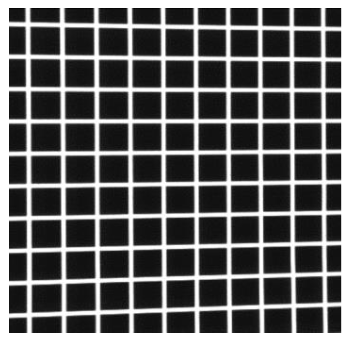
Generally, an SL system, using grid pattern only, has two components: a camera and a projector (Figure 1). The binary grid pattern is shown in Figure 2. The value Ow-XwYwZw is the world coordinate system, wherein the measured object is located. The value Oc-XcYcZc is the camera coordinate system, OI-XIYI is the physical image coordinate system, and o-UV is the pixel coordinate system corresponding to OI-XIYI. The projector casts the grid pattern onto the object. The camera captures the grid feature image indicating the object topography. Point M is one intersection of the grid pattern and the object surface. According to the pinhole model, the point m is the ideal (distortion-free) pixel point of the object point M. The measuring coordinate system is usually consistent with Oc-XcYcZc. Thus, the conversion function between m(u, v) and M(xc, yc, zc) can be expressed as [32]:
z c [ u v 1 ] = [ f x 0 u 0 0 f y v 0 0 0 1 ] [ R c w T c w ] [ x w y w z w 1 ] = [ f x 0 u 0 0 f y v 0 0 0 1 ] [ x c y c z c ]
where (xw, yw, zw) represents the coordinates of point M in Ow-XwYwZw; fx and fy are the camera pixel focal lengths in the horizontal ordinate direction, respectively; (u0, v0) are the coordinates of the principal point in o-UV; R c w and T c w represent the rotation matrix and the translational vector from Ow-XwYwZw to Oc-XcYcZc.
The projected grid pattern could be defined as multiple orthogonal light planes in Oc-XcYcZc. The equations of the planes are as follows [33]:
{ Π H i :   a H i x c + b H i y c + c H i z c + d H i = 0 ,       ( i = 1 , 2 , , n ) Π V j : a V j x c + b V j y c + c V j z c + d V j = 0 ,       ( j = 1 , 2 , , n )
where Π H i is the horizontal light plane; Π V j is the vertical light plane; [aHi, bHi, cHi, dHi] and [aVj, bVj, cVj, dVj] represent the four coefficients of each Π H i and Π V j , respectively; n is the number of the planes.
The pinhole model and the multiple light plane constraint, (xc, yc, zc) combined can be calculated using the following formula:
{ x c = ( u u 0 ) · z c f x y c = ( v v 0 ) · z c f y z c = d i a i · ( u u 0 ) f x + b i · ( v v 0 ) f y + c i
where [ai, bi, ci, di] is [aHi, bHi, cHi, dHi] or [aVj, bVj, cVj, dVj].
In addition, the distortion caused by the lens is inevitable. Considering the tangential distortion and radial distortion, the relationship between the actual (distorted) pixel coordinates (ud, vd) and ideal pixel coordinates (u, v) of point m can be expressed as [34]:
[ u d v d ] = ( 1 + k 1 r 2 + k 2 r 4 ) [ u v ] + [ 2 p 1 u v + p 2 ( r 2 + 2 u 2 ) 2 p 2 u v + p 1 ( r 2 + 2 v 2 ) ]
where r is the distance between (u, v) and (u0, v0); (k1, k2) are the radial distortion coefficients; (p1, p2) are the tangential distortion coefficients.

2.2. Extraction of the Grid Stripe Features

The grid pattern consists of a number of intersecting light stripes. The common algorithms for stripe center extraction are inaccurate [35,36]. The intersections of the grid lines could be precisely extracted based on our previous work [37]. Thus, an effective extraction method of the grid stripe features is proposed. The procedures of the method are as follows:
(1)
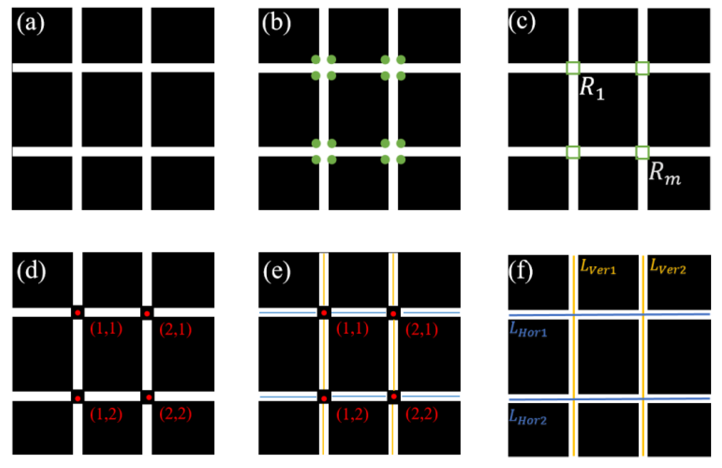
The corner points of the grid lines are detected by using the Shi-Tomasi algorithm [38]. The green points in Figure 3b indicate the corner of the intersecting lines.
(2)
Then the corner points are clustered into m groups by using the DBSCAN algorithm [39]. The points in the same group wrap one of the intersecting regions Ri (i = 1, 2, … m) as shown in Figure 3c.
(3)
After that, the center points of the regions can be easily obtained and sorted to be the markers (Figure 3d).
(4)
The gray centroid method is used to extract the strip centers between adjacent markers (Figure 3e). Finally, the horizontal stripes, LHi, and vertical stripes, LVj, are obtained and topologically labeled (Figure 3f).
During the calibration, the grid pattern should be projected on the calibration board (Figure 4). The white circles on the board can disturb the corner extraction (Figure 5b). To solve the problem, the gray value of the ellipse region on the input image is properly attenuated. The ellipses are extracted during the calibration. The maximum gray value in each ellipse is used as the threshold of gray filtering to remove the interference of the white circles. After the image gray attenuation, the corner detection of the output image (Figure 5d) can achieve the correct result (Figure 5e). Hence, the extraction of grid stripe features in a captured image is guaranteed by using the proposed algorithm. In Figure 6, the red lines tag the extracted horizontal stripes, while the yellow lines tag the vertical ones.

2.3. Calibration Procedures

According to the measuring principle of the SL system using a grid pattern, there are three categories of parameters which need to be calibrated: intrinsic parameters (fx, fy, u0, v0), distortion coefficients (k1, k2, p1, p2) and multiple light planes ( Π H i , Π V j ). By obtaining different pose views of a 2D coplanar point calibration board under several angles, all the parameters can be calibrated with a simple operation (Figure 7).
The procedures of the system calibration are shown in Figure 8. The calibration board as a target are placed in different poses (Figure 7). The grid pattern is projected on the board at each position. A set of target images and corresponding grid pattern images are acquired first.
The elliptic centers on each target image are extracted to provide the data for the camera calibration. By adopting Zhang’s method [40], the intrinsic parameters and distortion coefficients can be obtained. In addition, the rotation matrix Ri and translation vector Ti of each target pose can be calculated. The equations of the target planes in Oc-XcYcZc can be formed as:
a t i x c + b t i y c + c t i z c + d t i = 0
where n = [ati, bti, cti] is the third column of Ri, dtn = - n · T i . n = 1, 2,…, N. N is the total number of the positions.
Meanwhile, the stripe centers extraction is performed on the grid pattern images. The actual (distorted) pixel coordinates of the centers are labelled according to the topological relationship of the grids. The values m V i j n and m H i j n   are the actual pixel points on the vertical and horizontal stripes, respectively. Subsequently, the ideal (distortion-free) pixel points m V i j n and m H i j n are calculated by substituting the actual pixel coordinates and calibrated distortion coefficients into Equation (4). By combining Equations (1) and (5), the 3D coordinates of the ideal pixel points in Oc-XcYcZc can be obtained. The values M V i j n and M H i j n are the 3D grid feature points on the target planes and also the points on the grid light planes. Finally, the equations of the vertical and horizontal light planes can be fitted with the corresponding M V i j n and M H i j n .

3. Experiments and Discussion

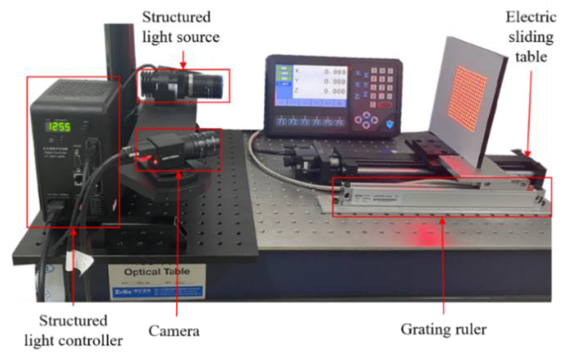
The experimental platform was constructed as shown in Figure 9. The camera was a Hikvision MV-CA013-21UM, with a 1280 × 1024 resolution. The focal length of the lens was 16 mm. Instead of utilizing a DLP projector, a low-cost LED projector was employed, which minimized the cost, reducing it by about 60%. The projector was the OPT structured light source OPT-SL03-R, with 16 × 16 grid stripes. The camera and the projector were aligned with an angle. The system parameters were calibrated in advance. An electric sliding table (Zolix TSA200) and a grating ruler with 1 µm accuracy were used to verify the precision of measurements. The algorithms and software were developed using Visual C# 2019 and opencv.
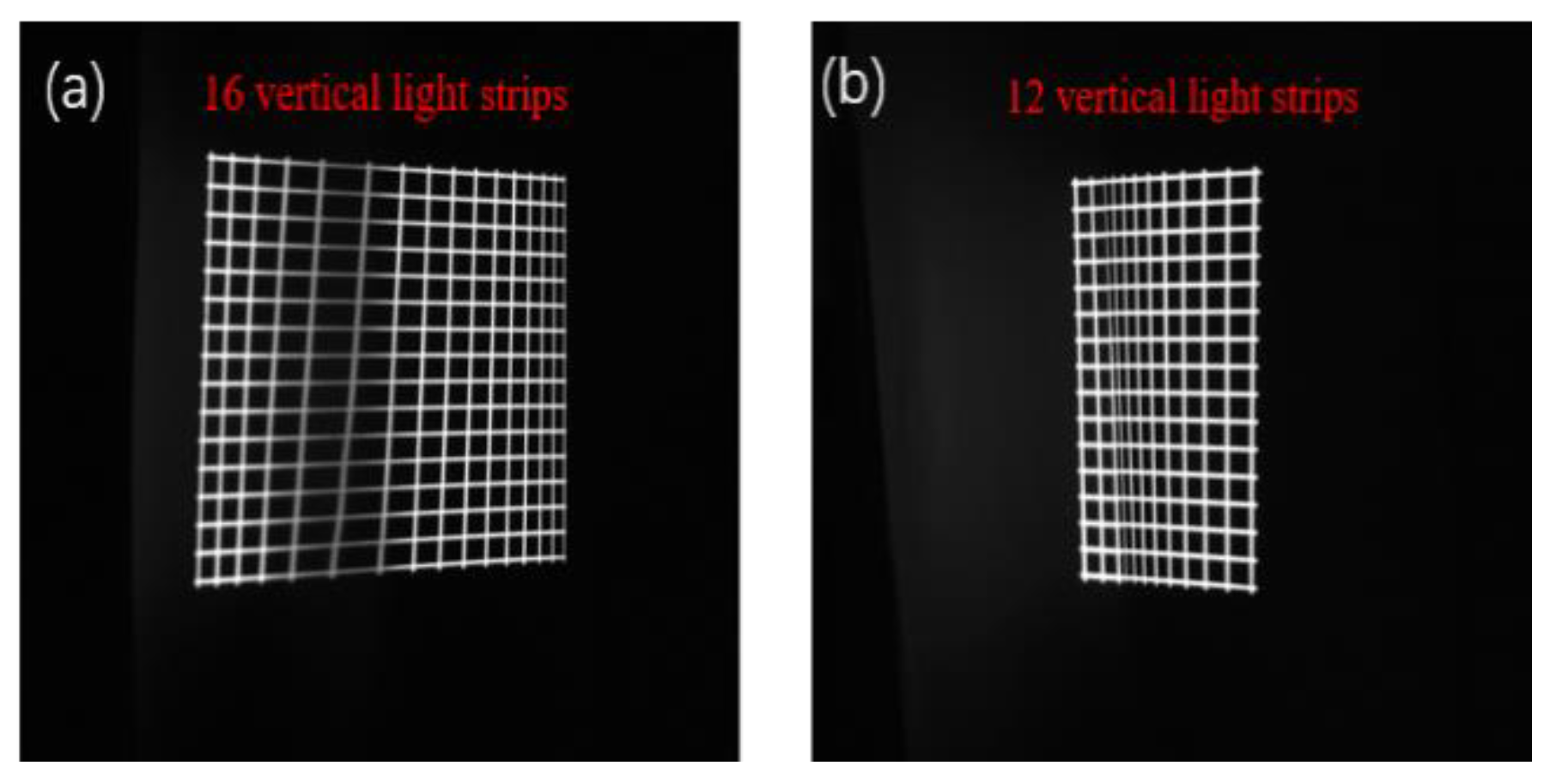
It should be noted that the grid pattern-based structured-light vision method suffers from a monotonicity constraint, even though it has many advantages in terms of higher accuracy and lower cost, compared with time-of-flight (ToF) and stereo vision [24]. The method is not capable of measuring large depth changes due to the monotonicity constraint. There is an upper bound of depth change. When all the local depth changes in a scene were less than the upper bound, the monotonicity constraint was satisfied, and, thus, all the light stripes could be obtained in the image (Figure 10a). The monotonicity constraint was violated when measuring depth changes over the upper bound, resulting in loss of light stripes (Figure 10b).
The upper bound of depth change, by employing the method is given by the following formula [24]:
Δ z = z 0 2 Δ d f p B + z 0 Δ d
where fp denotes the focal length of the projector, B denotes the length of the baseline, z0 denotes the reference depth, and Δd denotes the line interval in the projected grid. In our system, z0 = 450 mm, Δd = 0.45 mm, B = 250 mm, fp = 35 mm. Thus, the Δz = 10.179 mm.

3.1. System Calibration

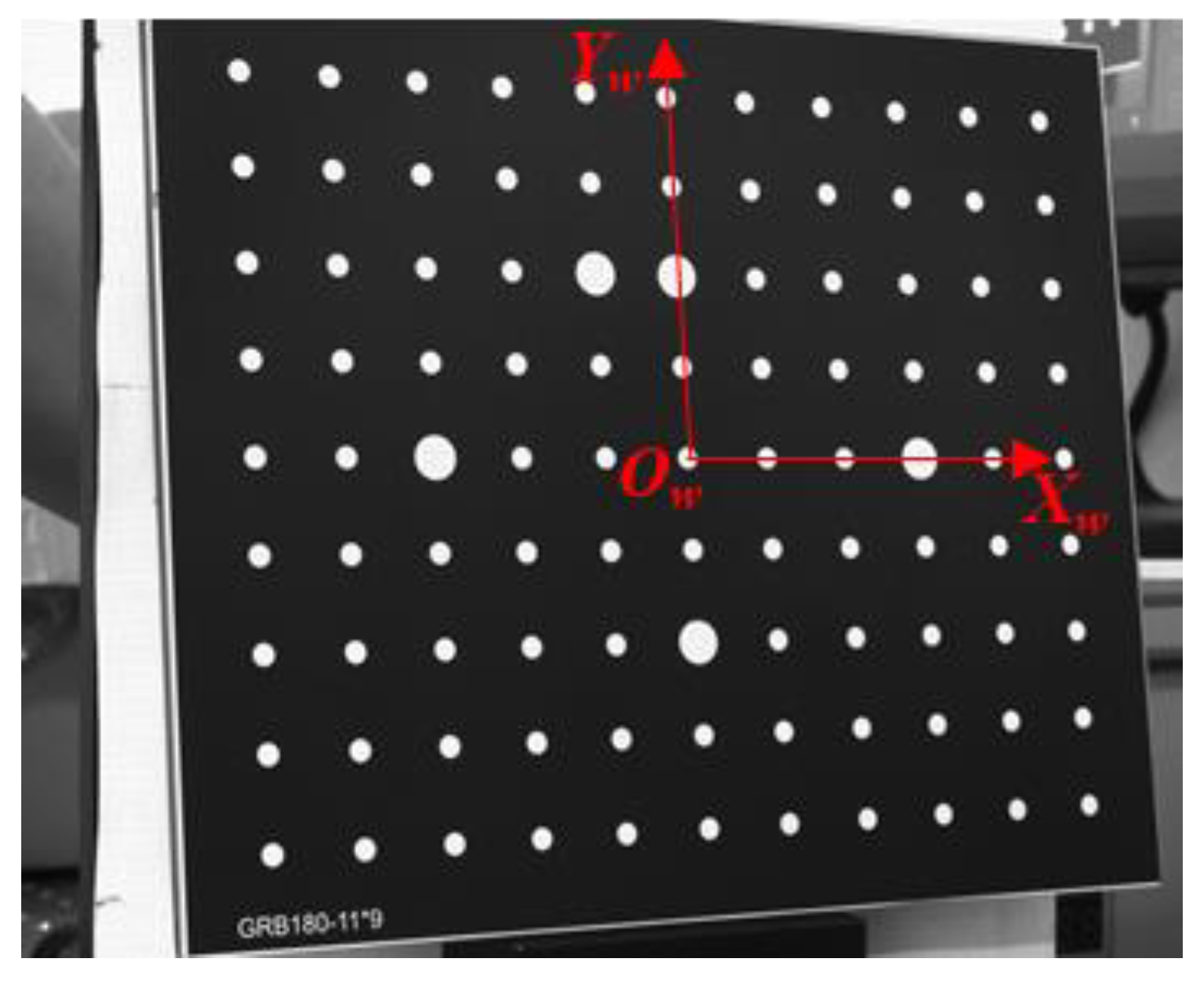
The 2D coplanar calibration board for the calibration had plenty of circular features (Figure 11). The specification of the target is shown in Table 1.
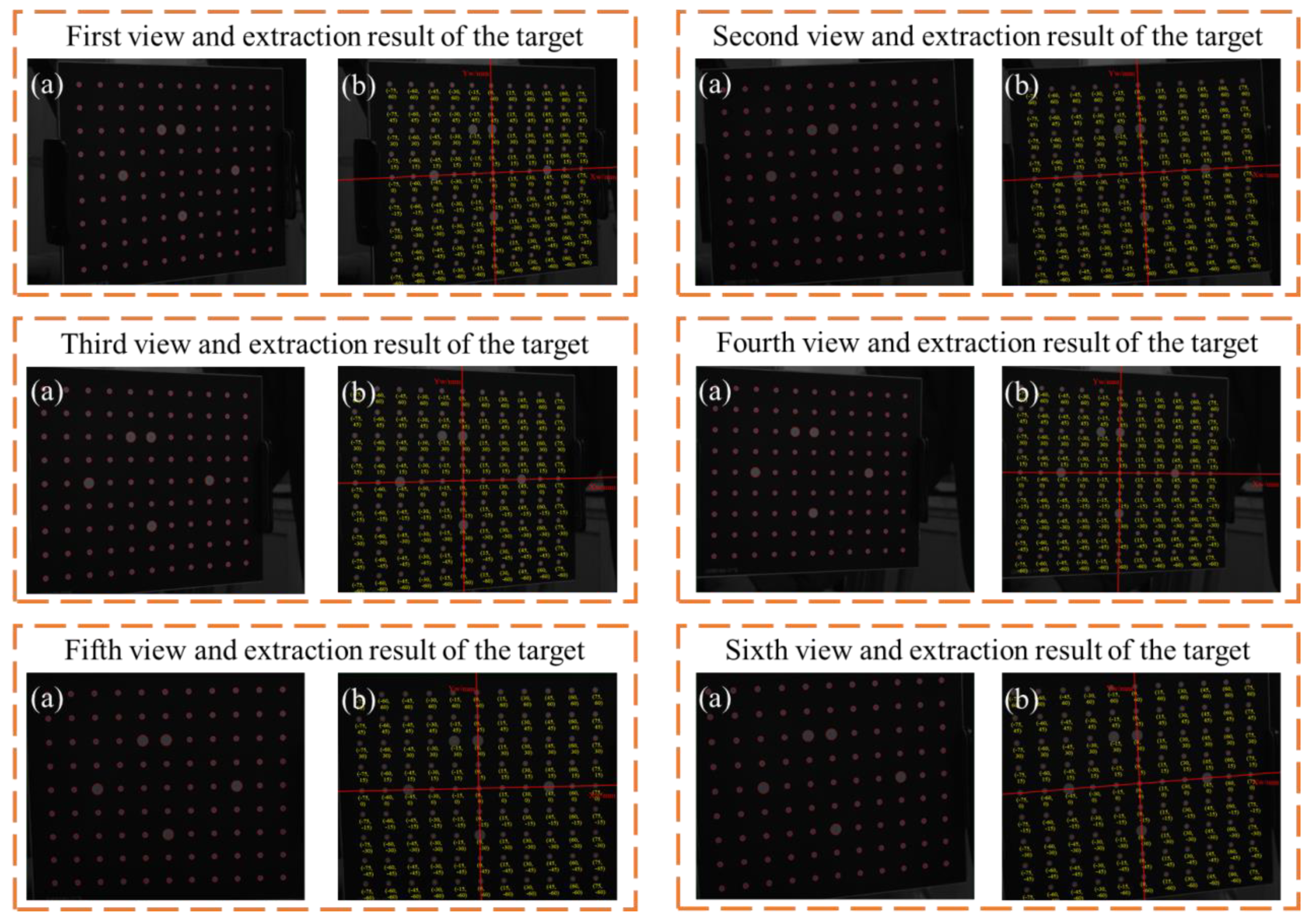
The target was placed at six different positions in the viewing field of the camera. The contour points of the white circles were extracted and fitted to the ellipses, as shown in Figure 12a. The ellipse centers were regarded as the feature points for calibration. The ellipse centers were sorted and marked according to topological ordering, as shown in Figure 12b.
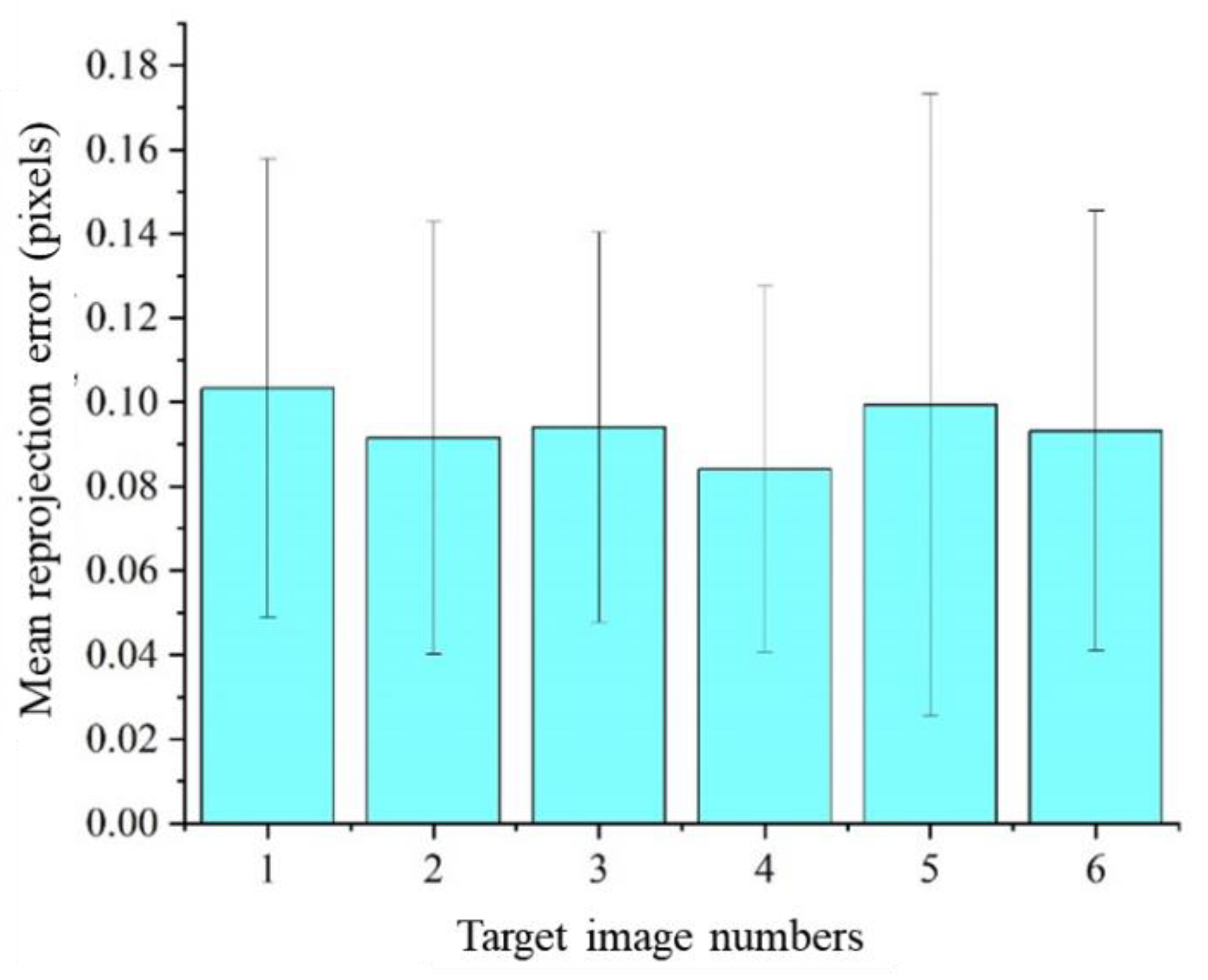
By utilizing Zhang’s method [40], the intrinsic parameters, distortion coefficients and relative poses Ri, Ti were obtained. The intrinsic parameters and distortion coefficients are listed in Table 2. The rotation matrix Ri was transformed into a vector formation rveci, consisting of Euler angles. The extrinsic parameters of the six pose views are listed in Table 3. The reprojection errors were the distances from the measured 2D points and their respective projections obtained by applying the calibrated camera model to the 3D points [41]. The mean reprojection errors of the six images were below 0.103 pixel, as shown in Figure 13.
There were sixteen horizontal and sixteen vertical planes on the grid pattern. The parameters of the light planes are listed in Table 4. The values [Aver, Bver, Cver, Dver] represent the coefficients of the vertical planes, while the values [AHor, BHor, CHor, DHor] represent the coefficients of the horizontal planes. The planes in the camera coordinate system are shown in Figure 14.

3.2. Measurement Verification

Displacement measurement experiments were conducted to evaluate the performance of the grid pattern-based structured-light vision method. A plane board was placed on the electrical sliding table and carried to several positions in front of the system. The electrical sliding table was equipped with a grating ruler (1 µm accuracy). The moving distances measured by the grating ruler were regarded as the ground truth. Three-dimensional coordinates of the grid pattern points on the board were obtained by the proposed method and fitted to planes at each location. The plane at the first position was regarded as the base plane. The distances from the 3D points on the other planes to the base plane were calculated sequentially. The measurement results and the corresponding ground truth values are listed in Table 5. The maximum relative error was 0.840%.
The 3D reconstruction of a gypsum sphere object was implemented in single-shot by using the grid pattern-based structured-light vision system. The Intel Realsense D455 is a popular RGB-D camera, using the speckle-based structured-light stereo vision method. As shown in Figure 15, a D455 camera was employed to reconstruct the same gypsum sphere. The approximate distance from the sphere to our system and the RGB-D camera was 450 mm.
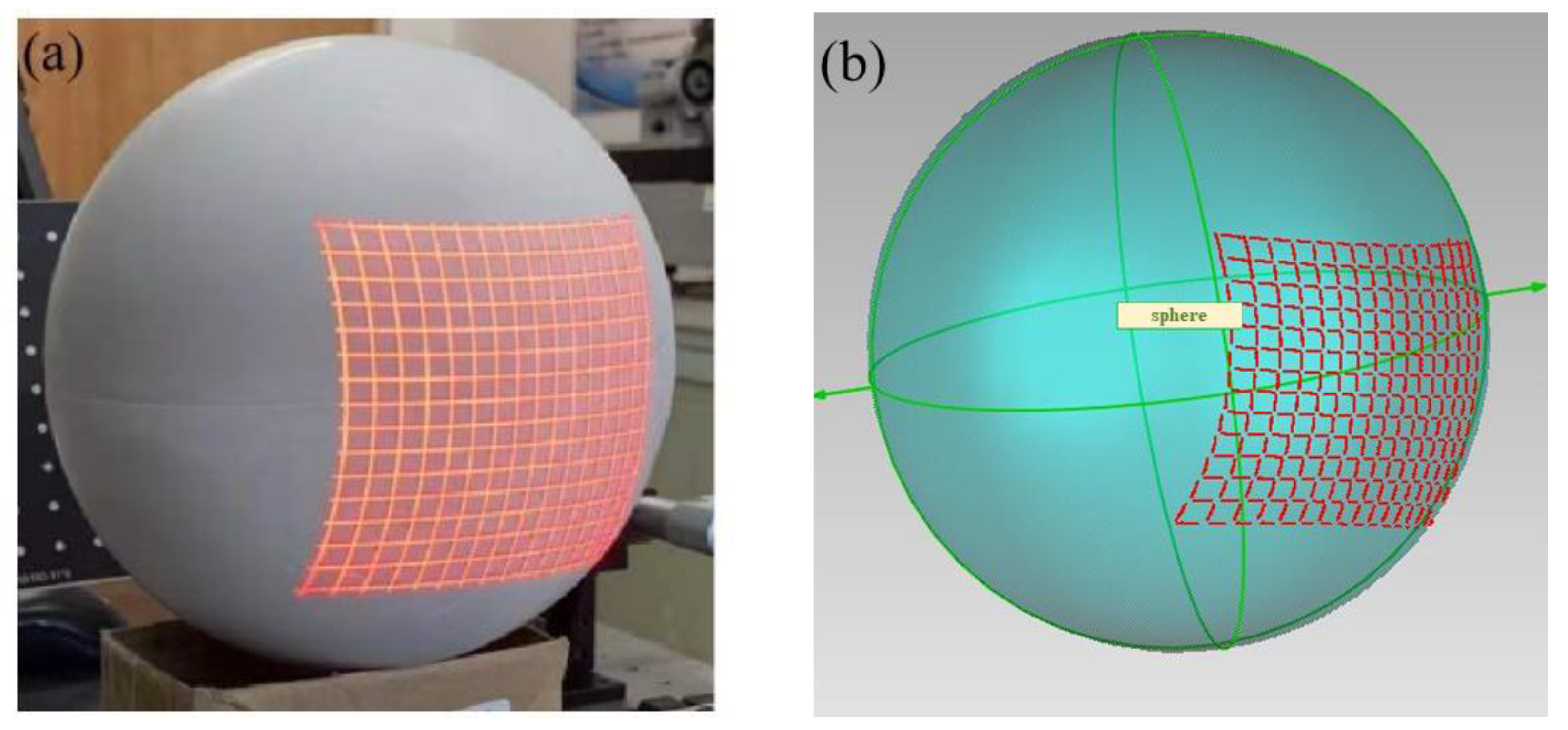
The experimental result using our approach is shown in Figure 16, while the result using the D455 camera is shown in Figure 17.
The nominal radius of the gypsum sphere was 85 mm. The 3D reconstruction data from our system and from the D455 camera were fitted to the sphere equation to calculate the measured radius. The measured radius of our approach and of that using D455 are listed in Table 6.

4. Conclusions

In this paper, a simple and effective single-shot 3D reconstruction approach, using the grid pattern-based structured-light vision method, was proposed. The system consisted of a camera and a low-cost LED projector.
The grid pattern-based structured-light model was combined with the camera pinhole model and the multiple light plane constraint. The tangential distortion and radial distortion were compensated for. Without the use of the epipolar constraint, the error propagation of the low calibration accuracy of the stereo vision model was avoided. The grid pattern consisted of a number of intersecting light stripes. The common algorithms for stripe center extraction are inaccurate. However, the intersections of the grid lines could be precisely extracted. Following the topological distribution of the intersections, an effective extraction method was investigated to gather the sub-pixel centers on the grid strips. The white circles on the calibration board could disturb the extraction. To solve the problem, the gray value of the ellipse region on the input image was properly and automatically attenuated. A calibration method, based on the coplanar constraint, was presented, which could be implemented in one step.
Displacement measurement experiments were conducted to evaluate the performance of the proposed method. The displacements measured by the grating ruler with 1 µm accuracy were regarded as the ground truth. The maximum relative error between the measurement results and the corresponding ground truth values was 0.840%. The 3D reconstruction of a sphere object was implemented in single-shot by using the grid pattern-based structured-light vision system. By comparing this with the reconstruction of the sphere from the commercial RGB-D camera, the proposed method was verified. Following the development of deep learning techniques, the detection and correspondence retrieval techniques of the grid pattern could achieve several innovations in the future.

Author Contributions

Conceptualization, G.W. and B.L.; methodology, G.W. and B.L.; software, F.Y. and Y.H.; validation, G.W., B.L. and F.Y.; formal analysis, B.L. and Y.Z.; investigation, B.L. and Y.Z.; resources, B.L. and Y.Z.; data curation, B.L., Y.H. and F.Y.; writing—original draft preparation, B.L. and F.Y.; writing—review and editing, G.W. and B.L.; visualization, F.Y. and Y.H.; supervision, G.W.; project administration, G.W.; funding acquisition, G.W., B.L. and F.Y. All authors have read and agreed to the published version of the manuscript.

Funding

This research was funded by the National Natural Science Foundation of China (51835007), Natural Science Foundation of Tianjin (21JCZDJC00760), “Project + Team” Key Training Fund of Tianjin (XC202054), Tianjin Graduate Scientific Research Innovation Project (2020YJSS013).

Institutional Review Board Statement

Not applicable.

Informed Consent Statement

Not applicable.

Data Availability Statement

The data presented in this research are available on request from the corresponding author.

Conflicts of Interest

The authors declare no conflict of interest.

References

  1. Cao, J.; Li, C.; Li, C.; Zhang, X.; Tu, D. High-reflectivity surface measurement in structured-light technique by using a transparent screen. Measurement 2022, 196, 111273. [Google Scholar] [CrossRef]
  2. Wang, H.; Ma, J.; Yang, H.; Sun, F.; Wei, Y.; Wang, L. Development of three-dimensional pavement texture measurement technique using surface structured light projection. Measurement 2021, 185, 110003. [Google Scholar] [CrossRef]
  3. Yang, G.; Wang, Y. Three-dimensional measurement of precise shaft parts based on line structured light and deep learning. Measurement 2022, 191, 110837. [Google Scholar] [CrossRef]
  4. Zhang, S. High-speed 3D shape measurement with structured light methods: A review. Opt. Lasers Eng. 2018, 106, 119–131. [Google Scholar] [CrossRef]
  5. Stempin, J.; Tausendfreund, A.; Stöbener, D.; Fischer, A. Roughness measurements with polychromatic speckles on tilted surfaces. Nanomanufacturing Metrol. 2021, 4, 237–246. [Google Scholar] [CrossRef]
  6. Wang, Z. Review of real-time three-dimensional shape measurement techniques. Measurement 2020, 156, 107624. [Google Scholar] [CrossRef]
  7. Li, R.; Li, F.; Niu, Y.; Shi, G.; Yang, L.; Xie, X. Maximum a posteriori-based depth sensing with a single-shot maze pattern. Opt. Express 2017, 25, 25332–25352. [Google Scholar] [CrossRef]
  8. Li, F.; Shang, X.; Tao, Q.; Zhang, T.; Shi, G.; Niu, Y. Single-shot depth sensing with pseudo two-dimensional sequence coded discrete binary pattern. IEEE Sens. J. 2021, 21, 11075–11083. [Google Scholar] [CrossRef]
  9. Pan, X.; Liu, Z. High-accuracy calibration of line-structured light vision sensor by correction of image deviation. Opt. Express 2019, 27, 4364–4385. [Google Scholar] [CrossRef]
  10. Li, W.; Hou, D.; Luo, Z.; Mao, X. 3D measurement system based on divergent multi-line structured light projection, its accuracy analysis. Optik 2021, 231, 166396. [Google Scholar] [CrossRef]
  11. Lu, X.; Wu, Q.; Huang, H. Calibration based on ray-tracing for multi-line structured light projection system. Opt. Express 2019, 27, 35884–35894. [Google Scholar] [CrossRef] [PubMed]
  12. Salvi, J.; Fernandez, S.; Pribanic, T.; Llado, X. A state of the art in structured light patterns for surface profilometry. Pattern Recognit. 2010, 43, 2666–2680. [Google Scholar] [CrossRef]
  13. Yin, W.; Feng, S.; Tao, T.; Huang, L.; Trusiak, M.; Chen, Q.; Zuo, C. High-speed 3D shape measurement using the optimized composite fringe patterns and stereo-assisted structured light system. Opt. Express 2019, 27, 2411–2431. [Google Scholar] [CrossRef] [PubMed]
  14. Zuo, C.; Feng, S.; Huang, L.; Tao, T.; Yin, W.; Chen, Q. Phase shifting algorithms for fringe projection profilometry: A review. Opt. Lasers Eng. 2018, 109, 23–59. [Google Scholar] [CrossRef]
  15. Vuylsteke, P.; Oosterlinck, A. Range image acquisition with a single binary-encoded light pattern. IEEE Trans. Pattern Anal. Mach. Intell. 1990, 12, 148–164. [Google Scholar] [CrossRef]
  16. Shi, G.; Yang, L.; Li, F.; Niu, Y.; Li, R.; Gao, Z.; Xie, X. Square wave encoded fringe patterns for high accuracy depth sensing. Appl. Opt. 2015, 54, 3796–3804. [Google Scholar] [CrossRef]
  17. Wang, L.; Chen, Y.; Han, X.; Fu, Y.; Zhong, K.; Jiang, G. A 3D shape measurement method based on novel segmented quantization phase coding. Opt. Lasers Eng. 2018, 113, 62–70. [Google Scholar] [CrossRef]
  18. Shoji, E.; Komiya, A.; Okajima, J.; Kubo, M.; Tsukada, T. Three-step phase-shifting imaging ellipsometry to measure nanofilm thickness profiles. Opt. Lasers Eng. 2019, 112, 145–150. [Google Scholar] [CrossRef]
  19. Fu, B.; Li, F.; Zhang, T.; Jiang, J.; Li, Q.; Tao, Q.; Niu, Y. Single-shot colored speckle pattern for high accuracy depth sensing. IEEE Sens. J. 2019, 19, 7591–7597. [Google Scholar] [CrossRef]
  20. Pagès, J.; Salvi, J.; Collewet, C.; Forest, J. Optimised de bruijn patterns for one-shot shape acquisition. Image Vis. Comput. 2005, 23, 707–720. [Google Scholar] [CrossRef]
  21. Albitar, C.; Graebling, P.; Doignon, C. Robust structured light coding for 3D reconstruction. In Proceedings of the 2007 IEEE 11th International Conference on Computer Vision, Rio De Janeiro, Brazil, 14–21 October 2007; pp. 1–6. [Google Scholar]
  22. Li, Q.; Li, F.; Shi, G.; Gao, S.; Li, R.; Yang, L.; Xie, X. One-shot depth acquisition with a random binary pattern. Appl. Opt. 2014, 53, 7095–7102. [Google Scholar] [CrossRef] [PubMed]
  23. Lavoie, P.; Ionescu, D.; Petriu, E. 3D object model recovery from 2D images using structured light. IEEE Trans. Instrum. Meas. 2004, 53, 437–443. [Google Scholar] [CrossRef]
  24. Shi, G.; Li, R.; Li, F.; Niu, Y.; Yang, L. Depth sensing with coding-free pattern based on topological constraint. J. Vis. Commun. Image Represent. 2018, 55, 229–242. [Google Scholar] [CrossRef]
  25. Salvi, J.; Batlle, J.; Mouaddib, E. A robust-coded pattern projection for dynamic 3D scene measurement. Pattern Recognit. Lett. 1998, 19, 1055–1065. [Google Scholar] [CrossRef] [Green Version]
  26. Sagawa, R.; Furukawa, R.; Kawasaki, H. Dense 3D reconstruction from high frame-rate video using a static grid pattern. IEEE Trans. Pattern Anal. Mach. Intell. 2014, 36, 1733–1747. [Google Scholar] [CrossRef]
  27. Je, C.; Lee, S.W.; Park, R.-H. High-contrast color-stripe pattern for rapid structured-light range imaging. In Proceedings of the Computer Vision—ECCV 2004, Prague, Czech Republic, 11–14 May 2004; Springer: Berlin/Heidelberg, Germany; pp. 95–107. [Google Scholar] [CrossRef]
  28. Jason, G.Z. Rainbow three-dimensional camera: New concept of high-speed three-dimensional vision systems. Opt. Eng. 1996, 35, 376–383. [Google Scholar]
  29. Ulusoy, A.O.; Calakli, F.; Taubin, G. Robust one-shot 3D scanning using loopy belief propagation. In Proceedings of the 2010 IEEE Computer Society Conference on Computer Vision and Pattern Recognition—Workshops, San Francisco, CA, USA, 13–18 June 2010; pp. 15–22. [Google Scholar]
  30. Ulusoy, A.O.; Calakli, F.; Taubin, G. One-shot scanning using De Bruijn spaced grids. In Proceedings of the 2009 IEEE 12th International Conference on Computer Vision Workshops, ICCV Workshops, Kyoto, Japan, 27 September–4 October 2009; pp. 1786–1792. [Google Scholar]
  31. Furukawa, R.; Kawasaki, H.; Sagawa, R.; Yagi, Y. Shape from grid pattern based on coplanarity constraints for one-shot scanning. IPSJ Trans. Comput. Vis. Appl. 2009, 1, 139–157. [Google Scholar] [CrossRef] [Green Version]
  32. Cui, Y.; Zhou, F.; Wang, Y.; Liu, L.; Gao, H. Precise calibration of binocular vision system used for vision measurement. Opt. Express 2014, 22, 9134–9149. [Google Scholar] [CrossRef]
  33. Wang, X.; Zhu, Z.; Zhou, F.; Zhang, F. Complete calibration of a structured light stripe vision sensor through a single cylindrical target. Opt. Lasers Eng. 2020, 131, 106096. [Google Scholar] [CrossRef]
  34. Liu, X.; Liu, Z.; Duan, G.; Cheng, J.; Jiang, X.; Tan, J. Precise and robust binocular camera calibration based on multiple constraints. Appl. Opt. 2018, 57, 5130–5140. [Google Scholar] [CrossRef]
  35. Qi, L.; Zhang, Y.; Zhang, X.; Wang, S.; Xie, F. Statistical behavior analysis and precision optimization for the laser stripe center detector based on Steger’s algorithm. Opt. Express 2013, 21, 13442–13449. [Google Scholar] [CrossRef] [PubMed]
  36. He, L.; Wu, S.; Wu, C. Robust laser stripe extraction for three-dimensional reconstruction based on a cross-structured light sensor. Appl. Opt. 2017, 56, 823–832. [Google Scholar] [CrossRef] [PubMed] [Green Version]
  37. Yang, F. Binocular measurement method using grid structured light. Chin. J. Lasers 2021, 48, 64–76. [Google Scholar]
  38. Shi, J. Good features to track. In Proceedings of the 1994 IEEE Conference on Computer Vision and Pattern Recognition, Seattle, WA, USA, 21–23 June 1994; pp. 593–600. [Google Scholar]
  39. Hou, J.; Gao, H.; Li, X. Dsets-DBSCAN: A parameter-free clustering algorithm. IEEE Trans. Image Process. 2016, 25, 3182–3193. [Google Scholar] [CrossRef] [PubMed]
  40. Zhang, Z. A flexible new technique for camera calibration. IEEE Trans. Pattern Anal. Mach. Intell. 2000, 22, 1330–1334. [Google Scholar] [CrossRef]
  41. Albarelli, A.; Rodolà, E.; Torsello, A. Robust camera calibration using inaccurate targets. In Proceedings of the British Machine Vision Conference, Aberystwyth, UK, 31 August–3 September 2010. [Google Scholar]
Figure 1. Schematic diagram of the SL system using grid pattern.
Applsci 12 10602 g001
Figure 2. The binary grid pattern.
Applsci 12 10602 g002
Figure 3. Schematic diagram of the grid stripe feature extraction. (a) Input image; (b) Corner detection result; (c) Intersecting regions; (d) Markers; (e) Strip centers; (f) Horizontal and vertical stripes.
Applsci 12 10602 g003
Figure 4. Grid pattern on the calibration board.
Applsci 12 10602 g004
Figure 5. Image gray attenuation for the grid pattern on white circles. (a) Input image; (b) The error occurred of corner detection on the input image; (c) Gray attenuation process; (d) The output image after the attenuation; (e) The correct corner detection result.
Applsci 12 10602 g005
Figure 6. Extraction of grid stripe feature in captured image.
Applsci 12 10602 g006
Figure 7. Schematic diagram of the system calibration.
Applsci 12 10602 g007
Figure 8. Calibration procedures.
Applsci 12 10602 g008
Figure 9. The experimental setup.
Applsci 12 10602 g009
Figure 10. The acquired images with depth variations in a target scene. (a) The image with all light stripes when the monotonicity constraint was satisfied; (b) The image with light strip loss during measuring depth changes over the upper bound.
Applsci 12 10602 g010
Figure 11. The acquired image of the calibration board.
Applsci 12 10602 g011
Figure 12. Different pose views and extraction results. (a) Ellipse fitting results of the different views. (b) Extracted feature centers and topological ordering results of the different views.
Applsci 12 10602 g012
Figure 13. The mean reprojection errors.
Applsci 12 10602 g013
Figure 14. The multiple light planes in the camera coordinate system. (a) Vertical light planes. (b) Horizontal light planes. (c) Space enclosed by the light planes.
Applsci 12 10602 g014
Figure 15. 3D reconstruction experiment using Intel Realsense D455.
Applsci 12 10602 g015
Figure 16. The 3D reconstruction of a sphere object using our approach. (a) Grid pattern image on the sphere; (b) Three-dimensional reconstruction result.
Applsci 12 10602 g016
Figure 17. The 3D reconstruction of the sphere object using D455. (a) Depth map; (b) Three-dimensional reconstruction result.
Applsci 12 10602 g017
Table 1. The specification of the target.
SpecificationsValues
Boundary dimensions (mm)180 × 150
Circle diameter (mm)7 (L), 3.5 (S)
Center distance (mm)15
Array number11 × 9
Precision (mm)±0.01
Table 2. The intrinsic parameters and distortion coefficients.
ParametersResults
fx, fy (pixel)3354.0982, 3354.8173
u0, v0 (pixel)697.163, 478.755
k1, k2−0.041, −1.344
p1, p2−0.00039, −0.00041
Table 3. The extrinsic parameters of the six pose views.
Pose ViewsrveciTi
1[−3.020, 0.046, −0.760][1.616, 5.987, 514.204]
2[−3.124, 0.083, −0.186][−8.074, 5.674, 511.550]
3[−3.048, 0.017, −0.677][−18.359, 5.856, 500.676]
4[−3.073, −0.015, −0.548][−25.7326, 0.505, 549.236]
5[−3.021, 0.031, −0.023][−7.029, 5.590, 469.236]
6[−2.990, 0.909, −0.355][−9.006, 2.654, 464.551]
Table 4. The parameters of the light planes.
ID[Aver, Bver, Cver, Dver][AHor, BHor, CHor, DHor]
1[0.807, 0.009, 0.59, −224.019][−0.041, 0.996, 0.807, 6.870]
2[0.814, 0.009, 0.579, −224.667][−0.035, 0.997, 0.071, 6.137]
3[0.821, 0.008, 0.569, −225.443][0.029, −0.998, −0.061, −5.225]
4[0.829, 0.008, 0.558, −225.711][−0.023, 0.999, 0.05, 4.704]
5[0.836, 0.007, 0.548, −226.566][−0.016, 0.999, 0.039, 4.195]
6[0.843, 0.007, 0.537, −226.901][−0.01, 0.999, 0.028, 3.694]
7[0.849, 0.007, 0.527, −227.53][−0.003, 0.999, 0.017, 3.244]
8[0.856, 0.006, 0.516, −227.949][0.004, 1.000, 0.006, 2.82]
9[0.863, 0.005, 0.505, −228.439][−0.01, −0.999, 0.005, −2.447]
10[0.869, 0.006, 0.493, −228.702][−0.017, −0.999, −0.015, 1.838]
11[0.875, 0.004, 0.483, −229.223][0.023, −0.999, −0.028, 1.98]
12[0.881, 0.004, 0.471, −229.522][0.029, 0.998, −0.037, 1.143]
13[0.897, 0.004, 0.46, −229.653][−0.036, −0.998, 0.049, −1.109]
14[0.893, 0.004, 0.449, −230.287][0.043, 0.997, −0.059, 0.085]
15[0.898, 0.003, 0.438, −230.369][0.048, 0.996, −0.069, −0.395]
16[0.903, 0.003, 0.428, −231.273][−0.054, −0.995, 0.078, 1.719]
Table 5. Accuracy verification experiment.
Ground Truth (mm)Measurement Results (mm)Errors (mm)Relative Errors
3.8623.8690.0070.181%
6.8386.824−0.014−0.205%
9.0458.969−0.076−0.840%
12.52412.475−0.049−0.391%
15.60115.514−0.087−0.558%
50.19020.039−0.151−0.748%
24.57324.558−0.015−0.061%
28.89228.879−0.013−0.045%
32.51132.5500.0390.120%
61.57161.7480.1770.287%
113.541113.8800.3390.299%
Table 6. The measured radius of our approach and D455.
Nominal Radius (mm)Our Approach (mm)D455 (mm)
85.00084.65288.937
Publisher’s Note: MDPI stays neutral with regard to jurisdictional claims in published maps and institutional affiliations.