Abstract
In this paper, an antenna with a multiple-input, multiple-output (MIMO) configuration is demonstrated for mm-wave 5G-based Internet of Things (IoT) applications. The two antenna elements are arranged next to each other to form a two-port antenna system such that significant field decorrelation is achieved. Moreover, a dielectric layer is backed by an eventual multiport system to amend and analyze the radiation characteristics. The overall size of the MIMO configuration is 14 mm × 20 mm, and the operation bandwidth achieves ranges from 16.7 to 25.4 GHz, considering the −10 dB criterion with a maximum isolation of more than −30 dB within the operating band. The peak gain offered by the antenna system is nearly 5.48 dB, and incorporating a dielectric layer provides an increase in the gain value to 8.47 dB. Within the operating band, more than 80% total efficiency is observed, and analysis shows several MIMO performance metrics with favorable characteristics. The compactness of the proposed design with high isolation, improved gain, and wideband features make it a suitable candidate for mm-wave-based 5G applications.
1. Introduction
The increase in annual data use by 40 to 70% has strained capacity requirements, representing an increase by 1000 times with the passage of time. Considering progressing data needs, 5G is a competent candidate adept to offer a data rate of multiple gigabits per second [1,2,3]. To accomplish the required goals, experts have focused on the mostly unoccupied portion of the spectrum, i.e., mm-wave, where high bandwidth achievement is possible, due in part to the limited bandwidth and capacity constraints of the lower portion of the spectrum (sub 6 GHz) [4,5]. Transmission based on 5G technology is not only intended to have high data rates and high quality of service but also to strengthen abilities of developing technologies, such as the Internet of Vehicles, virtual reality, smart cities etc. [6,7]. Frequency bands for communication networks must be carefully allocated, as several challenges arise with a particular band selection [8], which is why several frequency bands are being considered by various telecom regulatory bodies and various countries. Most of the bands that have been allocated for 5G communication are within the ranges of 24–28 GHz, 37–40 GHz, etc. [9]. However, path loss and atmospheric attenuations factors must be considered and solved before considering transmission at these frequency bands [10]. Furthermore, the bandwidth should be wide enough to offer significantly high data rates [11]. Thus, the role of antennas is key in this regard, and they must be carefully designed to realize 5G communication systems and to effectively benefit users [12].
5G systems will likely be built based on the multiantenna concept on both the transmission and receiver sides, making multiple input, multiple output (MIMO) configurations and also arrays are important in this regard [13]. To tackle attenuation-related issues in the case of mm-wave antennas, arrays are usually utilized to offer a narrow-beam radiation pattern [14]. However, these type of structures are focused on a single feed, and complex and simple power dividers are usually involved [15]. Controlling the losses in these type of power dividers is a challenging task, whereas a single feed results in limited capacity. Accommodating multiple antennas in an array structure to increase the gain also causes an increase in the profile [16]. Likewise, antennas incorporating lenses, metamaterials, and cavities are usually helpful to achieve high gain, and some antennas can maintain a low profile instead of high gain. For example, in [17], a DRA was developed with an EBG placed at a distance of 2.6 mm. The performance of the DRA was evaluated with and without an EBG. Overall, a 3 dB improvement in the gain was achieved. The size of the ground plane was 30 mm × 30 mm for the 60 GHz band. In [18], an EBG ground plane and a dielectric superstrate were utilized to improve the gain of the antenna, resulting in a gain of more than 16 dB. The superstrate was placed 5.35 mm above the main antenna array with a complex power divider. The array structure resulted in a larger PCB size, as a 12 mm separation was used between the antenna elements. A 28 GHz operating frequency antenna was proposed in [19], with a peak gain of 15.6 dB. A fractional bandwidth in the range of 26.5–29.4 GHz was attained. A 3D-printed dielectric lens was utilized to attain high gain. Moreover, 50 mm × 50 mm samples of polylactic acid (PLA) were fabricated. A complex structure was implemented in the proposed method to achieve high gain. However, the MIMO characteristic was lacking in the proposed designs, so capacity issues remained a challenge. Moreover, some of the proposed antennas lack a wide bandwidth. Recently, metamaterials with and without a combination of MIMO have been proposed. Antenna gain was improved by utilizing a three-pair metamaterial arrays in [20]. An overall gain of 7.4 dB was achieved, with bandwidth covering the range from 24.25 to 27.5 GHz and an overall size of 30.5 mm × 30 mm. Another antenna with an MIMO configuration was proposed in [21]; an electromagnetic band gap (EBG) configuration was adopted, increasing the gain by only 1.9 dB. Thus, an overall peak gain of 6 dB was achieved, with a bandwidth as high as 1 GHz. The size of the proposed EBG-based design is 27.5 mm × 27.5 mm. A dielectric resonator (DRA)-based MIMO antenna was proposed in [22], with an operating band range from 26.71 to 28.91 GHz. A peak gain of 7 dB was achieved after incorporating a metasurface with a DRA-based MIMO configuration such that the total size was 20 mm × 40 mm. A metamaterial surface was utilized as a reflector in [23] for an MIMO antenna system (two elements), resulting in a peak gain of 11.5 dB. The overall structure had a larger size of 31.7 mm × 53 mm. In [24], an MIMO antenna system (two elements) with a 8.6 dB peak gain was proposed with an operational bandwidth ranging from 29.7 to 31.5 GHz. Furthermore, the proposed structure had a large size of 48 mm × 21 mm. In [25], a MIMO antenna with a size of 95 mm × 80 mm was presented. The proposed design achieved a wide band but with many rapid jumps in the reflection coefficient, indicating that the reflection coefficient response was not smooth with a stable noise level variation at the transmission frequency band. Moreover, the large size represents a further constraint.
Overall, the use of metamaterial-based surfaces to improve the radiation characteristics of antennas is challenging in terms of controlling the capacitance and inductance in order to achieve a satisfactory output. As an alternative to metamaterial-based reflectors, surfaces are required for which capacitance and inductance can be easily controlled to enhance the radiation characteristics of the antennas, which is desirable for mm-wave communication. Moreover, wide bandwidth with a high gain requirement must be achieved in order to offer a high data rate, which is a promising feature of 5G technology. Due to the limitations observed, in this paper, we present a wideband, high-gain, and multiport antenna system (two antennas with two exciting sources). A compact antenna system is also proposed with a dielectric layer to improve the gain. Furthermore, to efficiently benefit from the MIMO system, high decorrelation in the radiation patterns is a desirable feature. Thus, a wideband ranging from 17.27 to 25.53 GHz with a total efficiency of more than 80% is achieved, with a peak gain of 8.47 dB, an isolation level of more than −30 dB, and the benefit of high decorrelation in radiation patterns.
2. Proposed Antenna Design Procedure
2.1. Antenna Element and MIMO Configuration
The geometry of the proposed design is demonstrated in Figure 1. A Rogers family substrate, i.e., RO-4350B with a thickness of 0.168 mm is used in the proposed design. The proposed system was designed and simulated using computer simulation technology (CST) software. A single element is backed by a truncated ground plane with a front side radiating structure modification to attain a wideband operation with optimal gain, efficiency, etc. Table 1 provides the dimensions summary of the proposed antenna element.
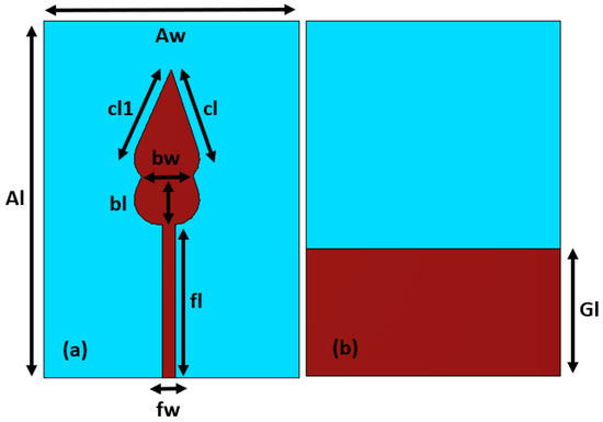
Figure 1.
Antenna element geometry: (a) front, (b) back.

Table 1.
Dimensions of the proposed antenna element.
The following expression can be utilized to estimate the feedline width [14].
The Equation (1) is based on a combination of components, i.e., feed line width (fw), impedance (Zo = 50 ohm), substrate thickness (h), and dielectric constant (εr). The reflection coefficient for the proposed antenna element is analyzed in Figure 2. Based on the −10 dB criterion, the response is well below −10 dB for the desired operational bandwidth. The design evolution steps of the proposed antenna are shown in Figure 2. Initially, a single radiating structure (step 1) provides a narrow bandwidth, whereas introducing a similar radiating structure on the top of the first radiating structure in step 2 yields an improvement in the bandwidth. Finally, in step 3, adding a sharp leaf-type radiating shape on the top of the first two structures results in a wider bandwidth. Thus, the structure achieved in step 3 is selected for subsequent processes, as it operates with a wide bandwidth and a meaningful magnitude of reflection coefficient. The basic antenna element (antenna) is a variation of the well-known circular broadband patch antenna tuned to work in the frequency range of 16.7–25.4 GHz. The mathematical modelling described in [26] was also helpful in determining the final design, including these design evolution steps. The single element is then extended to two-port MIMO configuration, as shown in Figure 3, such that it could be helpful to achieve field decorrelation. The overall dimensions of the proposed MIMO configuration are 14 mm × 20 mm × 0.168 mm.
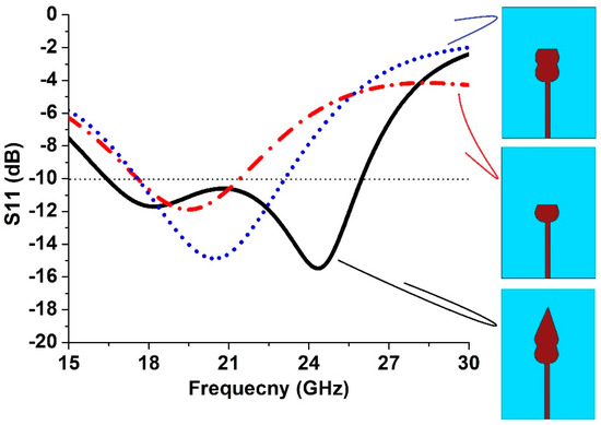
Figure 2.
Reflection coefficient comparison of the proposed antenna element design evolution steps.
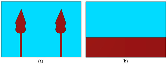
Figure 3.
MIMO antenna geometry: (a) front, (b) back.
The reflection coefficient for the proposed MIMO antenna is shown in Figure 4a, which is well below −10 dB. The isolation between the antenna elements is shown in Figure 4b. It is important to analyze the isolation between the MIMO antenna elements because it becomes an issue when more than one antenna element is assembled on a single printed circuit board (PCB) [27,28,29,30]. A maximum isolation level of more than −30 dB is achieved within the operating band. Overall, satisfactory likeness between the measured and simulated results is achieved. In the figures, sim. represents simulated results, whereas mea. represents measured results.
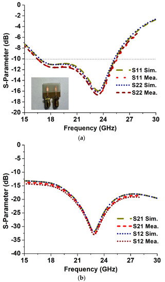
Figure 4.
Multiport antenna: (a) S-parameters, (b) isolation.
2.2. Antenna System Incorporated with a Dielectric Layer
An MIMO antenna incorporated with a dielectric layer is shown in Figure 5. A dielectric layer with overall dimensions of 20 mm × 26 mm × 2 mm is placed below a proposed MIMO configuration at a distance of 4 mm. Moreover, the dielectric constant is maintained at 12 to ensure that the proposed dielectric layer has a significant beam concentration. The overall aim is to improve the radiation performance of the proposed antenna system. The reflection coefficient of the proposed MIMO antenna after incorporating a dielectric layer is analyzed in Figure 6a, and the isolation is shown in Figure 6b, which is more than −30 dB (maximally) within the operating band. Here, we suggest that after incorporating a dielectric layer, both antennas will still achieve similar results, which will be helpful to attain high data rates, which is among the main features of MIMO-based 5G transmission. Furthermore, a gain comparison is shown in Figure 7 for an antenna with and without a dielectric layer. The peak gain in the case of an antenna without an external layer is 5.48 dB, whereas when a dielectric layer is incorporated, the peak gain increases to 8.47 dB within the operating band due to the highly dielectric nature of the layer incorporated on the back of MIMO antenna. Owing to the highly capacitive nature of the dielectric layer, it serves as a suitable reflective surface, resulting in the focusing of the fringing fields and an overall improvement in the gain. In the future, a dielectric layer with nearly the same dielectric constant value will be utilized to validate the simulated results based on the dielectric layer.

Figure 5.
MIMO antenna incorporated with a dielectric layer.
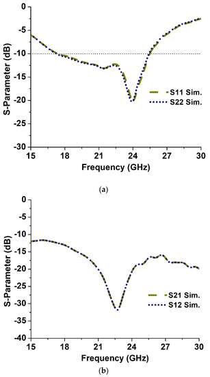
Figure 6.
S-parameters based on antenna incorporation with a dielectric layer: (a) reflection coefficient, (b) isolation.
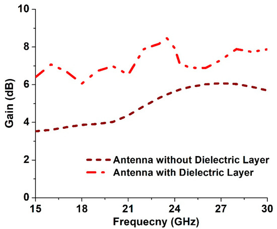
Figure 7.
Proposed MIMO antenna gain comparison with and without a dielectric layer.
The following expression [31] can be utilized to estimate the distance between the proposed MIMO system and the dielectric layer to achieve a satisfactory output performance.
The equation is based on a combination of components, i.e., free space propagation constant (β), reflection phase (φ), and distance (H) between the dielectric layer and the antenna configuration (π = 3.1415).
2.3. Radiation Pattern in Terms of Gain
In Figure 8, the simulated polar radiation patterns are compared for an antenna with and without a dielectric layer in the E-plane and H-plane in the 23.5 GHz frequency band. To efficiently benefit from the MIMO system, high decorrelation in the radiation patterns is a desirable feature. As shown in Figure 8, ports 1 and 2, the radiation pattern is well-de-correlated, indicating that one-antenna radiation results in low overlapping with the other one antenna within the same panel. This can be help to achieving sufficiently diverse performance. The total efficiency in the desired frequency band without a dielectric layer is 87.8%, whereas after incorporating a dielectric layer, the total efficiency is 89.6%. The gain measured at multiple frequency points for an antenna without a dielectric layer is compared with the simulated gain in Table 2.
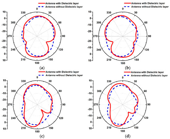
Figure 8.
Antenna polar radiation patterns in: (a) E-plane port 1, (b) E-plane port 2, (c), H-plane port 1, and (d) H-plane port 2.
Table 2.
Gain measurement of the proposed antenna.
2.4. MIMO Performance Metrics
Several MIMO performance metrics were analyzed for the proposed antenna system incorporated with a dielectric layer, such as envelope correlation coefficient (ECC), channel capacity loss (CCL), and diversity gain (DG). In Figure 9, the ECC is demonstrated using the far-field calculation method [31], which conforms with the standard value (<0.5), whereas in Figure 10, DG is analyzed, which is close to the standard value, i.e., 10 dB. Moreover, in Figure 11, CCL is shown. A CCL value of less than 0.4 bits/s/Hz is achieved across the operating band, which depicts a minimal capacity loss. It is important to analyze this loss because when more than one antenna is incorporated to form an antenna system, the channel capacity is increased, but some losses are encountered due to the correlation between the MIMO links. In [32], a channel capacity of 41 bps/Hz was observed for the sub 6 GHz band, with a low isolation value of −14.8 dB. CCL was not analyzed, and the size of the proposed design was relatively large, i.e., >80 mm. An MIMO antenna with a size of 150 mm × 80 mm was presented in [33]; a channel capacity of 41 bps/Hz was achieved, but no analysis of CCL was presented. The proposed MIMO antenna achieved an isolation of less than −15 dB within the 5150–5925 MHz frequency band, which may result in deterioration of the transmission quality. The same idea was implemented in [34], in which CCL was not taken into account and a relatively larger antenna of more than 80 mm was reported to have a low operating bandwidth, i.e., less than 1 GHz.
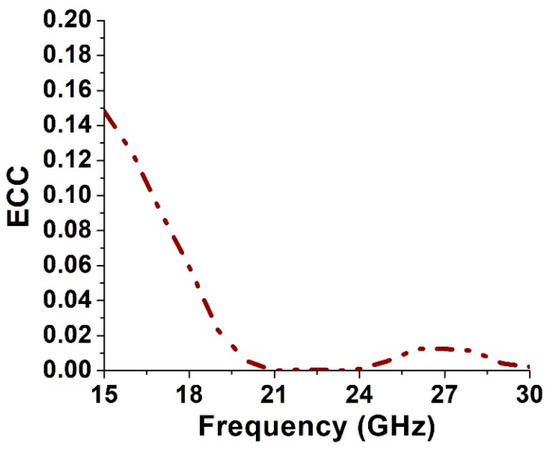
Figure 9.
ECC of the proposed antenna system incorporated with a dielectric layer.
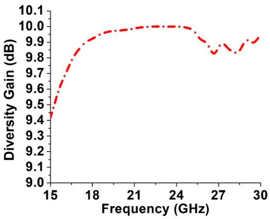
Figure 10.
DG of the proposed antenna system incorporated with a dielectric layer.
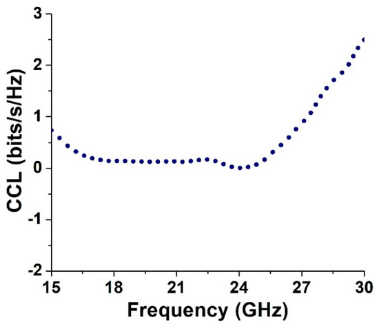
Figure 11.
CCL of the proposed antenna system incorporated with a dielectric layer.
3. Conclusions
In this paper, we demonstrated an antenna with a multiple input, multiple output (MIMO) configuration for mm-wave 5G applications. The two antenna elements are sequenced in series to form a two-port antenna system such that significant field decorrelation is achieved. Moreover, a dielectric layer is backed by the proposed MIMO antenna to improve and analyze the radiation characteristics. The overall size of the MIMO configuration is 14 mm × 20 mm, with an operation bandwidth in the range of 16.7–25.4 GHz, considering the −10 dB criteria with a maximum isolation of more than −30 dB within the operating band. The peak gain offered by the proposed antenna system is nearly 5.48 dB, and deploying a dielectric layer increases the gain value to 8.47 dB. A total efficiency of more than 80% is achieved within the operating band, and several MIMO performance metrics were analyzed, revealing satisfactory characteristics, making the proposed design a suitable candidate for mm-wave-based 5G applications. In the future, beam-steering techniques will be incorporated to achieve satisfactory cell transmission coverage.
Author Contributions
Conceptualization, D.A.S.; Data curation, M.A. (Mujeeb Abdullah); Formal analysis, W.A.S.; Funding acquisition, N.U.; Investigation, J.K.; Project administration, S.A.; Supervision, M.A. (Muhammad Asif). All authors have read and agreed to the published version of the manuscript.
Funding
The authors would like to thank Taif University Researchers, Taif University, Taif, Saudi Arabia, for supporting project number TURSP-2020/228.
Conflicts of Interest
The authors declare that they have no conflict of interest to report regarding the present study.
References
- Kiani, S.H.; Iqbal, A.; Wong, S.-W.; Savci, H.S.; Alibakhshikenari, M.; Dalarsson, M. Multiple elements MIMO antenna system with broadband operation for 5th generation smart phones. IEEE Access 2022, 10, 38446–38457. [Google Scholar] [CrossRef]
- Alibakhshikenari, M.; Ali, E.M.; Soruri, M.; Dalarsson, M.; Naser-Moghadasi, M.; Virdee, B.S.; Stefanovic, C.; Pietrenko-Dabrowska, A.; Koziel, S.; Szczepanski, S.; et al. A comprehensive survey on antennas on-chip based on metamaterial, metasurface, and substrate integrated waveguide principles for millimeter-waves and terahertz integrated circuits and systems. IEEE Access 2022, 10, 3668–3692. [Google Scholar] [CrossRef]
- Thompson, J.; Ge, X.; Wu, H.; Irmer, R.; Jiang, H.; Fettweis, G.; Alamouti, S. 5G wireless communication systems: Prospects and challenges [guest editorial]. IEEE Commun. Mag. 2014, 52, 62–64. [Google Scholar] [CrossRef]
- Wei, L.; Hu, R.Q.; Qian, Y.; Wu, G. Key elements to enable millimeter wave communications for 5G wireless systems. IEEE Wireless Commun. 2014, 21, 136–143. [Google Scholar]
- Hussain, M.; Mousa Ali, E.; Jarchavi, S.M.R.; Zaidi, A.; Najam, A.I.; Alotaibi, A.A.; Althobaiti, A.; Ghoneim, S.S.M. Design and characterization of compact broadband antenna and its MIMO configuration for 28 GHz 5G applications. Electronics 2022, 11, 523. [Google Scholar] [CrossRef]
- Rappaport, T.S.; Sun, S.; Mayzus, R.; Zhao, H.; Azar, Y.; Wang, K.; Wong, G.N.; Schulz, J.K.; Samimi, M.; Gutierrez, F. Millimeter wave mobile communications for 5G cellular: It will work! IEEE Access 2013, 1, 335–349. [Google Scholar] [CrossRef]
- Alibakhshikenari, M.; Virdee, B.S.; See, C.H.; Shukla, P.; Moghaddam, S.M.; Zaman, A.U.; Shafqaat, S.; Akinsolu, M.O.; Liu, B.; Yang, J.; et al. Dual-polarized highly folded bowtie antenna with slotted self-grounded structure for Sub-6 GHz 5G applications. IEEE Trans. Antennas Propag. 2022, 70, 3028–3033. [Google Scholar] [CrossRef]
- European 5G Observatory. National 5G Spectrum Assignment. Available online: https://5gobservatory.eu/ (accessed on 10 May 2020).
- Hussain, N.; Jeong, M.; Abbas, A.; Kim, N. Metasurface-based single-layer wideband circularly polarized MIMO antenna for 5G millimeter-wave systems. IEEE Access 2020, 8, 130293–130304. [Google Scholar] [CrossRef]
- Ojaroudiparchin, N.; Shen, M.; Pedersen, G.F. Beam-steerable microstrip-fed bow-tie antenna array for fifth generation cellular communications. In Proceedings of the 2016 10th European Conference on Antennas and Propagation (EuCAP), Davos, Switzerland, 10–15 April 2016; pp. 1–5. [Google Scholar]
- Sharaf, M.H.; Zaki, A.I.; Hamad, R.K.; Omar, M.M.M. A Novel Dual-Band (38/60 GHz) Patch Antenna for 5G Mobile Handsets. Sensors 2020, 20, 2541. [Google Scholar] [CrossRef]
- Barreto, A.N.; Faria, B.; Almeida, E.; Rodriguez, I.; Lauridsen, M.; Amorim, R.; Vieira, R. 5G–Wireless Communications for 2020. J. Commun. Inf. Syst. 2016, 31. [Google Scholar] [CrossRef]
- Li, M.Y.; Ban, Y.L.; Xu, Z.Q.; Guo, J.; Yu, Z.F. Tri-polarized 12-Antenna MIMO array for future 5G smartphone applications. IEEE Access 2017, 6, 6160–6170. [Google Scholar] [CrossRef]
- Khan, J.; Sehrai, D.A.; Ali, U. Design of dual band 5G antenna array with SAR analysis for future mobile handsets. J. Electr. Eng. Technol. 2019, 14, 809–816. [Google Scholar] [CrossRef]
- Li, Y.; Luk, K.-M. Wideband perforated dense dielectric patch antenna array for millimeter-wave applications. IEEE Trans. Antennas Propag. 2015, 63, 3780–3786. [Google Scholar] [CrossRef]
- Ta, S.X.; Choo, H.; Park, I. Broadband printed-dipole antenna and its arrays for 5G applications. IEEE Antennas Wireless Propag. Lett. 2017, 16, 2183–2186. [Google Scholar] [CrossRef]
- Al-Hasan, M.J.; Denidni, T.A.; Sebak, A.R. Millimeter-wave EBG-based aperture-coupled dielectric resonator antenna. IEEE Trans. Antennas Propag. 2013, 61, 4354–4357. [Google Scholar] [CrossRef]
- Haraz, O.M.; Elboushi, A.; Alshebeili, S.A.; Sebak, A. Dense dielectric patch array antenna with improved radiation characteristics using EBG ground structure and dielectric superstrate for future 5G cellular networks. IEEE Access 2014, 2, 909–913. [Google Scholar] [CrossRef]
- Malik, B.T.; Doychinov, V.; Zaidi, S.A.R.; Robertson, I.D.; Somjit, N. Antenna gain enhancement by using low-infill 3D-printed dielectric lens antennas. IEEE Access 2019, 7, 102467–102476. [Google Scholar] [CrossRef]
- Attia, H.; Abdelghani, M.L.; Denidni, T.A. Wideband and high-gain millimeter-wave antenna based on FSS Fabry–Perot cavity. IEEE Trans. Antennas Propag. 2017, 65, 5589–5594. [Google Scholar] [CrossRef]
- Iqbal, A.; Basir, A.; Smida, A.; Mallat, N.K.; Elfergani, I.; Rodriguez, J.; Kim, S. Electromagnetic bandgap backed millimeter-wave MIMO antenna for wearable applications. IEEE Access 2019, 7, 111135–111144. [Google Scholar] [CrossRef]
- Murthy, N.S. Improved isolation metamaterial inspired mm-wave MIMO dielectric resonator antenna for 5G application. Prog. Electromagn. Res. C 2020, 100, 247–261. [Google Scholar] [CrossRef]
- Saad, A.A.R.; Mohamed, H.A. Printed millimeter-wave MIMO based slot antenna arrays for 5G networks. AEU Int. J. Electron. Commun. 2019, 99, 59–69. [Google Scholar] [CrossRef]
- Sharawi, M.S.; Podilchak, S.K.; Hussain, M.T.; Antar, Y.M.M. Dielectric resonator based MIMO antenna system enabling millimeter wave mobile devices. IET Microw. Antennas Propag. 2017, 11, 287–293. [Google Scholar] [CrossRef]
- Gotra, S.; Varshney, G.; Pandey, V.S.; Yaduvanshi, R.S. Super-wideband multi-input–multi-output dielectric resonator antenna. IET Microw. Antennas Propag. 2019, 14, 21–27. [Google Scholar] [CrossRef]
- Ahmad, S.; Ijaz, U.; Naseer, S.; Ghaffar, A.; Qasim, M.A.; Abrar, F.; Parchin, N.O.; See, C.H.; Abd-Alhameed, R. A jug-shaped CPW-fed ultra-wideband printed monopole antenna for wireless communications networks. Appl. Sci. 2022, 12, 821. [Google Scholar] [CrossRef]
- Alibakhshikenari, M.; Khalily, M.; Virdee, B.S.; See, C.H.; Abd-Alhameed, R.A.; Limiti, E. Mutual-coupling isolation using embedded metamaterial EM bandgap decoupling slab for densely packed array antennas. IEEE Access 2019, 7, 51827–51840. [Google Scholar] [CrossRef]
- Alibakhshikenari, M.; Babaeian, F.; Virdee, B.S.; Aïssa, A.; Azpilicueta, L.; See, C.H.; Althuwayb, A.A.; Huynen, I.; Abd-Alhameed, R.A.; Falcone, F.; et al. A comprehensive survey on “various decoupling mechanisms with focus on metamaterial and metasurface principles applicable to SAR and MIMO antenna systems”. IEEE Access 2020, 8, 192965–193004. [Google Scholar] [CrossRef]
- Alibakhshikenari, M.; Khalily, M.; Virdee, B.S.; See, C.H.; Abd-Alhameed, R.A.; Limiti, E. Mutual coupling suppression between two closely placed microstrip patches using EM-bandgap metamaterial fractal loading. IEEE Access 2019, 7, 23606–23614. [Google Scholar] [CrossRef]
- Alibakhshikenari, M.; Virdee, B.S.; See, C.H.; Abd-Alhameed, R.A.; Ali, A.H.; Falcone, F.; Limiti, E. Study on isolation improvement between closely-packed patch antenna arrays based on fractal metamaterial electromagnetic bandgap structures. IET Microw. Antennas Propag. 2018, 12, 2241–2247. [Google Scholar] [CrossRef]
- Asif, M.; Sehrai, D.A.; Kiani, S.H.; Khan, J.; Abdullah, M.; Ibrar, M.; Alibakhshikenari, M.; Falcone, F.; Limiti, E. Design of a Dual Band SNG Metamaterial Based Antenna for LTE 46/WLAN and Ka-Band Applications. IEEE Access 2021, 9, 71553–71562. [Google Scholar] [CrossRef]
- Thakur, V.; Jaglan, N.; Gupta, S.D. Side edge printed eight-element compact MIMO antenna array for 5G smartphone applications. J. Electromagn. Waves Appl. 2022, 36, 1685–1701. [Google Scholar] [CrossRef]
- Jaglan, N.; Gupta, S.D.; Kanaujia, B.K.; Sharawi, M.S. 10 element sub-6-GHz multi-band double-T based MIMO antenna system for 5G smartphones. IEEE Access 2021, 9, 118662–118672. [Google Scholar] [CrossRef]
- Jaglan, N.; Gupta, S.D.; Sharawi, M.S. 18 Element Massive MIMO/Diversity 5G Smartphones Antenna Design for Sub-6 GHz LTE Bands 42/43 Applications. IEEE Open J. Antennas Propag. 2021, 2, 533–545. [Google Scholar] [CrossRef]
Publisher’s Note: MDPI stays neutral with regard to jurisdictional claims in published maps and institutional affiliations. |
© 2022 by the authors. Licensee MDPI, Basel, Switzerland. This article is an open access article distributed under the terms and conditions of the Creative Commons Attribution (CC BY) license (https://creativecommons.org/licenses/by/4.0/).