Article

Practical Experience in the Application of Energy Roofs, Ground Heat Storages, and Active Thermal Protection on Experimental Buildings

1
Faculty of Civil Engineering, Slovak University of Technology, Radlinského 11, 81005 Bratislava, Slovakia
2
Engineer in the Field of Energy Efficiency of Buildings, Topolčianska 5, 85105 Bratislava, Slovakia
*
Author to whom correspondence should be addressed.
Appl. Sci. 2022, 12(18), 9313; https://doi.org/10.3390/app12189313
Submission received: 25 July 2022 / Revised: 22 August 2022 / Accepted: 24 August 2022 / Published: 16 September 2022
(This article belongs to the Special Issue New Developments and Prospects in Clean and Renewable Energies)

Abstract

:
Research Area: Building components with integrated energy-active elements (BCEAE) are generally referred to as combined building-energy systems (CBES). Aim: Research on the application of energy (solar) roofs (ESR), ground heat storage (GHS), active thermal protection (ATP), and their cooperation in different modes of operation of energy systems with an emphasis on the use of renewable energy sources (RES) and waste heat. Methodology: The analysis and synthesis of the state of the art in the field, the inductive and analogical form of the creation of an innovative method of operation of combined building-energy systems, the development of an innovative solution of the envelope panel with integrated energy-active elements, the synthesis of the knowledge obtained from the scientific analysis and the transformation of the data into the design and implementation of the prototype of the prefabricated house IDA I and the experimental house EB2020. Results: The theoretical analysis of building structures with active thermal protection results in the determination of their energy potential and functionality, e.g., thermal barrier, heating/cooling, heat storage, etc. New technical solutions for envelopes with controlled heat transfer were proposed based on the implementation of experimental buildings. Conclusions: The novelty of our research lies in the design of different variants of the way of operation of energy systems using RES and in upgrading building envelope panels with integrated energy-active elements.

1. Introduction

Combined building-energy systems (CBES) are building components with energy-active components (BCEAE) that capture and/or store renewable energy sources (RES), in particular solar energy, geothermic energy, and energy from the surroundings, and then actively use them. Our research focuses mainly on energy (solar) roofs (ESR), ground heat storages (GHS), and active thermal protection (ATP) applied in building envelopes. Existing combined building-energy systems such as ISOMAX [1], which uses ESR and GHS as heat/cool sources, and thermal barrier (TB) to eliminate heat loss/gain of the building, can be considered as starting points in this research area. Envelope building structures using ATP can include thermally activated building structure (TABS) systems; for example, the REHAU system [2], as well as envelope panels with massive absorbers on the exterior side used to capture solar and ambient energy as a register for heat pumps, such as the RIEDER system [3].
In analyzing and synthesizing the findings in this area of research, we have drawn on several studies by researchers from around the world. In the literature review, we present the most relevant related studies.
We used the following literature as a background for the energy (solar) roof:
Li et al. [4], 2016, reported that the accurate calculation of solar energy on the rooftops of buildings in high-density residential development determines the critical role in renewable energy’s sustainable development and consumption. Light detection and ranging (LiDAR) data-based conventional solar radiation models are only appropriate for existing structures. The authors calculated the capacity of solar energy on rooftops using a pixel-based methodology. Buildings with flat roofs in a recently planned development region were chosen for the case study. The pixel unit is a mathematical formulation of the solar radiation in a specific cell. Image processing was used to compute the yields over a period of time while accounting for various instantaneous sun intensities. Solar radiation varied significantly throughout both time and space, according to measurements. Within the research region, radiation outputs were expected to range from 34,258 MJ/m2/year to 471,772 MJ/m2/year, respectively. Radiation contours were subsequently created to map various solar installation locations. Twenty percent of the roof space on any residential structure may provide at least 4500 MJ/m2 of solar radiation per year. The accuracy of the study’s predictions of solar radiation potential and its ability to pinpoint regions of strong radiation over building rooftops will be useful to energy investors and urban planners. The findings can be incorporated into public policy and city planning to promote the usage of renewable energy.
Michael and Selvarasan [5], 2017, explored a solar water heating system and a solar photovoltaic system that can substantially reduce household energy consumption. They have been dealing with innovative designs over the decades that have greatly improved the performance of solar collectors. However, they found that the choice of construction material plays a fundamental role in reducing the solar collector’s weight, costs, energy, and CO2 emissions. This paper compares a solar PV/Tna water heating system with a solar PV system and a flat plate solar water heating (SWH) system based on the economic and environmental evaluation. The obtained results show that with higher overall efficiency, the solar PV/T system has a better benefit ratio than the solar PV system while being competitive with the solar thermal system. It also makes the best use of the available home roof space and minimizes the number of building materials and the payback period. Moreover, the built-in energy and built-in CO2 emissions of the PV/T collector are smaller than the other two solar energy systems combined.
Walch et al. [6], 2020, discuss large-scale photovoltaic (PV) installations. To assess the technical suitability of such installations for specific roof regions, they created a methodology that integrates machine learning algorithms, geographic information systems, and physical models with hourly temporal resolution. To quantify the uncertainty in the final PV potential, they further evaluate the uncertainties linked to each stage of the capacity assessment and combine them. The approach is used on 9.6 million Swiss rooftops, but it may be applied to any sizable area or nation given enough data. The results show that it is possible in Switzerland to install PV panels on 55% of the total roof area, representing the annual technical potential of PV panels on roofs. This would make it possible to cover more than 40% of Switzerland’s current annual electricity demand. The reported method of hourly estimation of rooftop PV potential and uncertainty applies to a broad assessment of future energy systems with decentralized electricity grids. The results can be used to design effective strategies for integrating rooftop PV systems into the built environment.
As a background for long-term heat accumulation, we used the following literature:
Lazzarotto’s [7] 2015 paper is devoted to developing thermal modeling of borehole heat storage systems. The major goal was to improve physical phenomena representation by introducing aspects typically not employed in current models. The mathematical description of the borehole heat exchanger network’s structure and the modeling of borehole fields with variable borehole orientation are included in these services. A network model was used to approach the detailed modeling of the topology of borehole heat exchangers. Components are smaller, discrete versions of the larger geothermal system. These are interconnected through a network to build the logical connections required to define a certain borehole connection geometry. His method shows that combining a sufficient system discretization and network representation yields the granularity or flexibility required to describe any wellfield connection configuration.
According to Haq and Hiltunen’s work from 2019 [8], they looked at how a ground source heat storage system responded thermally during two successive charging intervals from June 2016 to August 2017. In the summer, the ground source heat storage system holds the thermal energy that the solar collectors collected. In order to maximize the efficiency of the ground heat storage, the authors created a charging method based on the findings of the experimental measurements. According to the study’s findings, the ground warmed from 8 to 18 °C in a year. Over a five-year operating period, a temperature distribution of 24 °C was assumed for the ground source heat store. The temperature response of the ground source heat store is expected to range from 18 °C to 34 °C over a year for injection power adjustments from 30 kW to 60 kW. The average multi-year heat transfer in ordinary ground storage in Finland is estimated to be 1.2 GJ.
Sun et al. [9], 2020, describe the design of a novel solar-powered ground-source heat pump (SAGSHP) system with a thermal cascade formed by borehole heat exchangers in North China. The core and peripheral regions of the borehole heat exchangers were separated into two groups. A high temperature, such as 45 °C, which is substantially higher than in earlier research, can be maintained in the core region. Without using the heat pump, it is possible to use the heat from this region directly. The outcomes show that a suitable soil temperature gradient may be established and maintained. The monthly average borehole-wall temperature difference between borehole heat exchangers in the core and at the periphery can be up to 30.1 °C. This points to the possibility of implementing both cascading heat storage and heat recovery. In addition, an average performance of CCOP = 5.15 (coefficient of performance for the compressor) and SCOP = 4.66 (coefficient of performance for the system) can be achieved. Compared to previous studies, it can be concluded that despite the lower CCOP, a higher SCOP can be achieved due to heat cascade storage and utilization. The new approach described in this paper presents a viable alternative for space heating in North China.
For active thermal protection (thermal barrier), we used the following literature as a background:
Li et al. [10], 2016, researched and designed a new low-quality energy utilization system, i.e., j. pipe-embedded wall integrated with a heat exchanger connected to a ground source, investigating its energy-saving potential in five typical climate regions of China. The study results show that the proposed system’s energy saving potential varies depending on the climatic regions. With an equally large system of built-in pipes, building in warm climates achieves the highest percentage of energy savings. It is followed by buildings in a hot summer and cold winter region, a strong cold climate region, a cold climate region, and a hot summer and warm winter region in descending order of energy saving. Meanwhile, a multi-criteria performance evaluation was also carried out in order to find the optimal size of the low-energy system in each climate region. The proposed system can be used in practice to save energy, and the results of the study are helpful in guiding the practical applications of the system of walls inserted into pipes in different climatic regions.
Kisilewicz et al. [11], 2019, present the results and analysis of research they conducted in an experimental residential building in Nyiregyhaza, Hungary. An innovative system of direct connection of a ground heat exchanger to a wall heat exchanger is installed in the building. The author of this system, Tamas Barkanyi, was awarded a patent for active thermal insulation of buildings in 2012. The authors address the problem of to what extent an active insulation system can participate in the replacement of standard passive insulation systems. Initial research results show that active thermal insulation has a beneficial effect on improving the insulation performance of the envelope wall. The overall reduction of heat loss through the external wall ranged from 53% to 81% in the periods analyzed from February to November. The equivalent heat transfer coefficient Ueq of the analyzed wall depended on the local climatic conditions and was 0.047 W/(m2·K) in November and 0.11 W/(m2·K) in March, while the standard value of the heat transfer coefficient was 0.282 W/(m2·K). The positive research results should be the basis for implementing the innovative system in near-zero energy buildings.
Iffa et al. [12], 2022, investigated thermal energy storage systems in buildings that can store energy for cooling/heating during off-peak hours or when are renewable energy sources available for later use. In this study, a wall system equipped with an active insulation system and a thermally activated storage system was designed, and its performance for active cooling energy contribution was studied. The performances of energy storage (charging), energy release (discharging) of thermal energy storage, and active insulation systems were studied separately and together as an integrated system. The results showed that the thermal properties of the thermal energy storage core material, the spacing of the pipes embedded in the thermal energy storage, and the hydronic pipes used in the active insulation system had the greatest influence on the wall properties of all the tested parameters of the wall system.
The beginning of our team’s research activities in the field of CBES dates to 2003/2004. Our research has focused on the application of energy (solar) roofs (ESR), ground heat storage (GHS), active thermal protection (ATP), and their cooperation in different modes of operation of energy systems with an emphasis on the use of renewable energy and waste heat.
The theoretical assumptions have been experimentally verified on IDA I (Ida—the first name of the wife of the sponsor of the research and implementation of the experimental building) and EB2020 (energy building meeting the requirements for nearly Zero Energy Buildings from 2020) buildings designed and implemented by us. A detailed description of the research, development, design, and implementation of the IDA I prototype prefabricated house with combined building-energy systems using RES is part of the study carried out based on the work contract HZ 04-309-05 (Kalús: responsible researcher) [13], 2005. The theoretical analysis and computer simulation of selected circuit panels with integrated energy-active elements were elaborated by Cvíčela M. (supervisor: Kalús) in his dissertation thesis [14].
Between 2011 and 2013, research was carried out on an experimental family house, EB2020, which was designed to use solar and geothermic energy. The basic CBES using RES of this building include energy (solar) roof (ESR), ground heat storage (GHS), and envelope constructions with active thermal protection (ATP). We designed this house, managed its construction, and conducted experimental measurements under different heat sources and energy system operations. A detailed description of the research is part of the study carried out under the contract HZ PG73/2011 (Kalús: responsible researcher) [15], 2013. Theoretical analysis and experimental measurements of the operation of the energy (solar) roof (ESR), ground heat storage (GHS), and active thermal protection (ATP) were developed by Janík D. (supervisor: Kalús) also in his Ph.D. thesis [16].
CBES is divided into source elements of energy systems and end elements of energy systems, Figure 1.
Our research is based on the analysis and synthesis of the current state of the art in the field. We developed innovative ways of operating combined building-energy systems using inductive and analogical scientific methods. We designed and developed innovative envelope panel solutions with integrated energy-active elements. We developed mathematical-physical models for building envelopes with ATP and analyzed their energy potential. Based on synthesizing the knowledge obtained from scientific analysis and data transformation, we designed and implemented a prototype of the IDA I prefabricated house and the experimental house EB2020. The novelty of our research lies in the design of different variants of the method of operation of energy systems using RES and in upgrading building envelope panels with integrated energy-active elements. Our research aims to design and optimize variants of Combined Building-Energy Systems (CBES) that will represent energy reliable, safe, and environmentally friendly technical solutions. Furthermore, to analyze building structures with active thermal protection to determine their energy potential and functionality, e.g., thermal barrier, heating/cooling, heat storage, etc. Based on experimental buildings to verify the theoretical assumptions, optimize the operation of CBES, and propose new technical solutions for envelopes with controlled heat transfer. The results of our research have been processed into three utility models [17,18,19] and one European patent [20].

2. Materials and Methods

In Section 2.1, we focused on the description of the materials used in the context of the research described in this study. Section 2.2 describes the most important scientific methods used in the research.

2.1. Materials

For parametric studies used to determine the energy potential of building envelopes with integrated energy-active elements based on mathematical-physical models, we used calculation software developed in MS Excel.
The theoretical analysis and computer simulation in ANSYS software of selected circuit panels with integrated energy active elements was carried out by Cvíčela M. (supervisor: Kalús) in his Ph.D. thesis [14].
AUTOCAD software was used in the design, development, and projects of the prototype prefabricated house IDA I and the experimental house EB2020. The technical standards in force at the time were also applied.
Different measuring instruments were used in the experimental measurements on the experimental house EB2020 [15,16]:
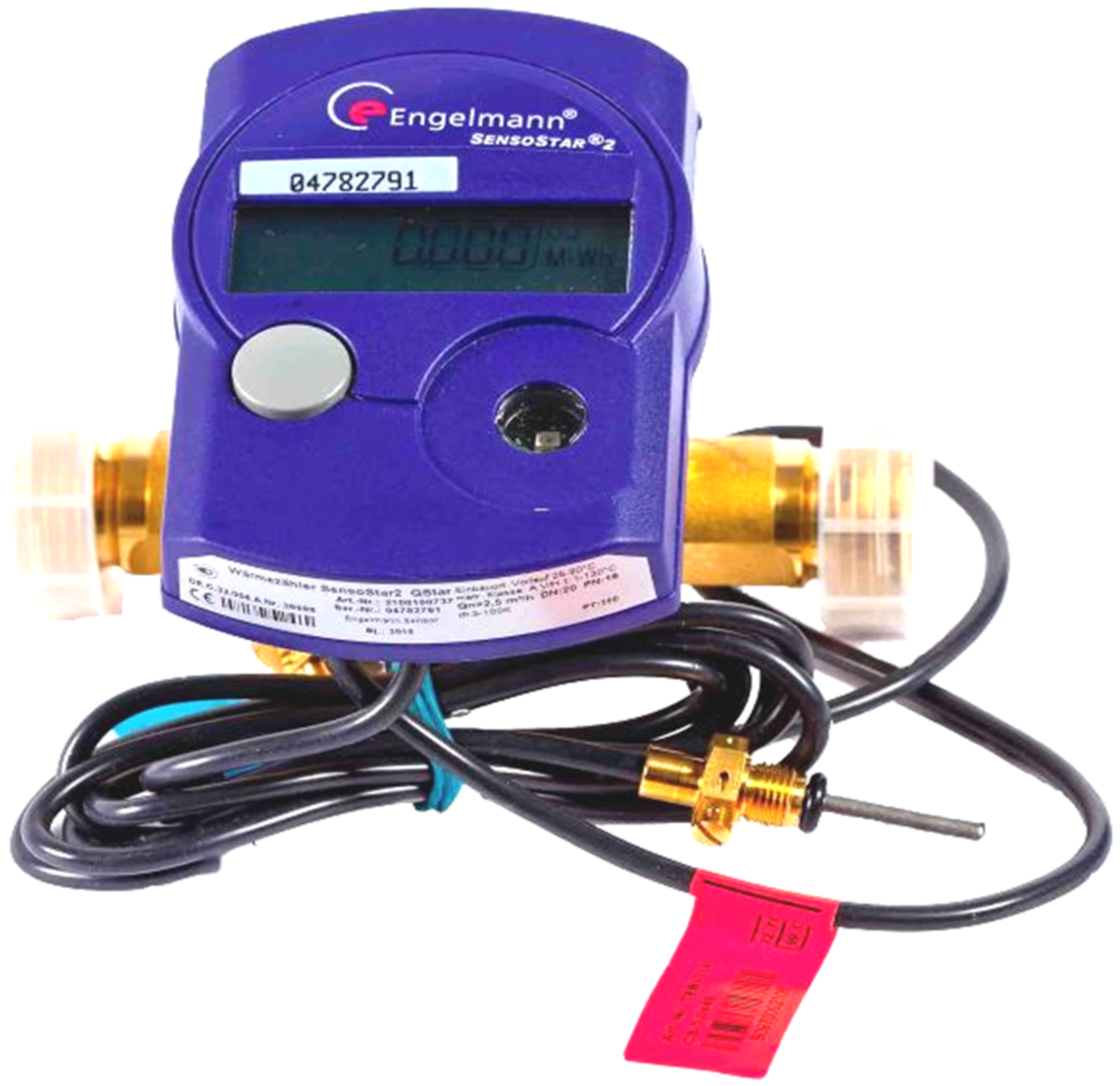
Engelmann Sensostar2 compact heat meters,
Testo 845 infrared thermometer,
MobIR M4 portable infrared camera.
Engelmann Sensostar2 Compact heat meters are fixed in the experimental house EB2020 at the energy roof (measured behind the plate heat exchanger), the fireplace insert, the gas boiler, and the ground source heat store active thermal protection and the underfloor heating. Two compact heat meters are fitted at the ground storage tank to measure the values during the charging and discharging cycles (heat supply to the energy system from the heat storage tank). The temperature in the supply and return pipes (°C), power (kW), flow (m3/h), flowed volume (m3), and heat (GJ) can be measured using the measuring device. The compact meter is shown in Figure 2. Figure 3 shows the measuring and recording control panel for data acquisition with automatic data transfer to software available via the Internet.
The infrared thermometer Testo 845 was used for non-contact measurement of surface temperatures of building structures (°C). It is shown in Figure 4. The MobIR M4 portable infrared camera was used to detect heat leakage, temperature distribution on building structures, and the location of ATP pipes. It is shown in Figure 5.

2.2. Methods

In this section, we describe the most important scientific methods we applied in our research:
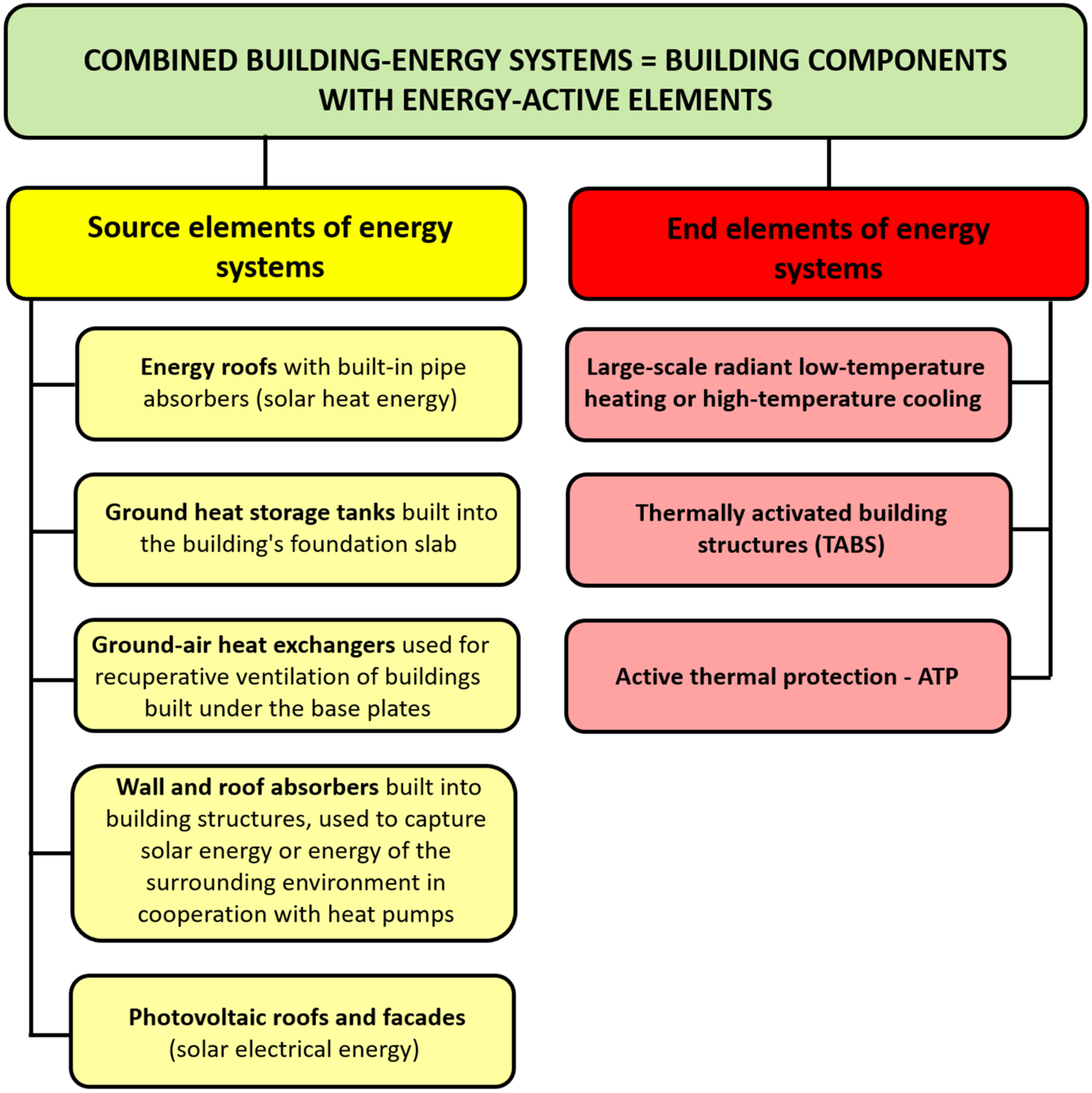
Analysis and synthesis of knowledge in the field of energy (solar) roofs, ground heat storage, and active thermal protection (thermal barriers and other energy functions), Introduction;
Analysis and description of basic calculation procedures for sizing energy (solar) roofs, published in [21], ground heat storage, published in [22], and active thermal protection, published in [23];
Inductive and analog form of creating variants of an innovative way of operation of combined building-energy systems, Section 2.2.1;
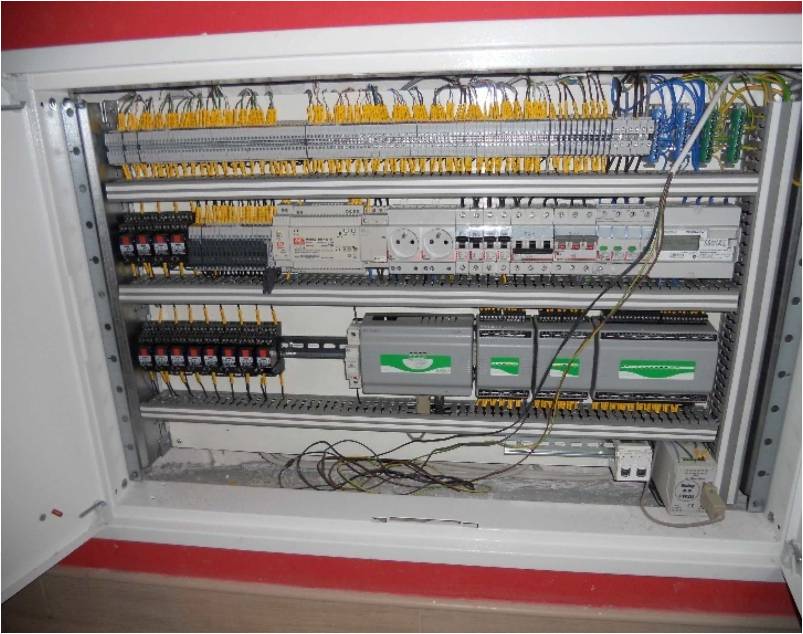
Development of an innovative circuit panel solution with integrated energy-active elements, Section 2.2.2;
Development of mathematical-physical models of envelopes with active thermal protection, Section 2.2.3;
Parametric study and analysis of the energy potential of active thermal protection in the function of thermal barrier, Section 3.1.1;
Synthesis of the knowledge obtained from the scientific research and transformation of the data into the design and implementation of the IDA I prefabricated house prototype, Section 3.1.2, and the EB2020 experimental house, Section 3.1.3;
Experimental measurements, analysis, and synthesis of measured physical quantities, verification of theoretical assumptions, and calculations for energy (solar) roofs have been published in the study [21], and for ground source heat storage have been published in the study [22].

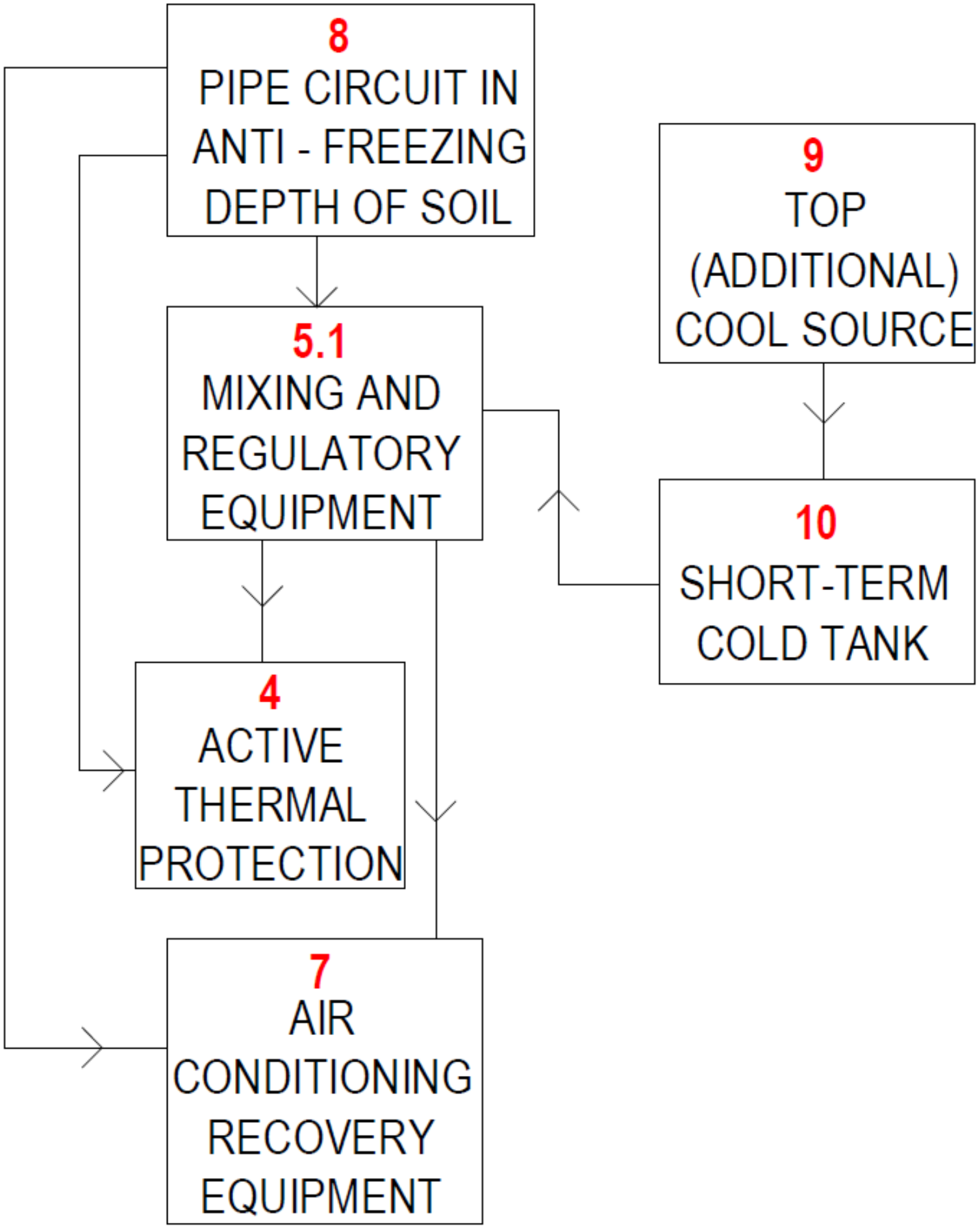
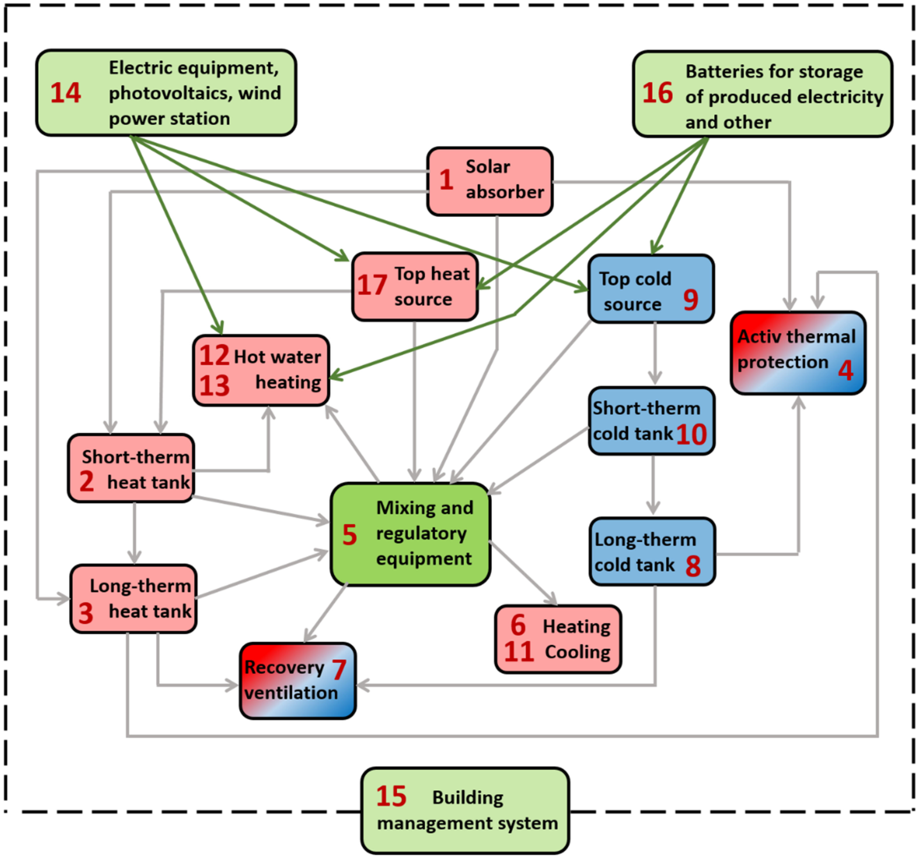
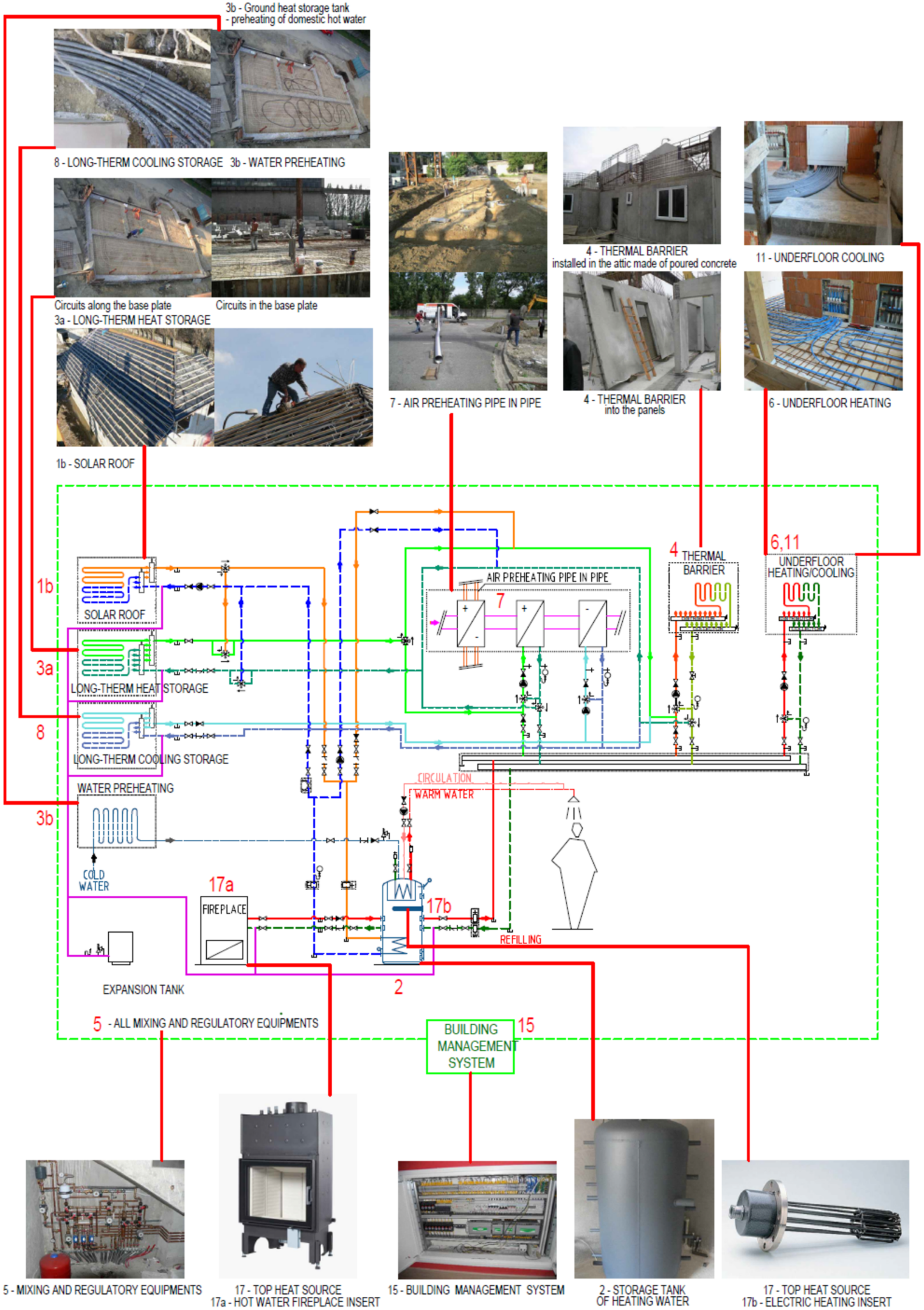
2.2.1. The Inductive and Analogical Form of Creating an Innovative Way of Operating a Combined Building-Energy System

Based on the results of our research, we have proposed innovation on how to operate RES-based CBES in cooperation with building envelope panels with embedded energy-active components. The complex creation of an indoor climate of buildings considering long-term or immediate requirements is based on the use of different options for the combination of heat absorption, heat, and cold production, thermal or cooling energy storage, active thermal protection, large-scale and hot-air heating, ventilation, cooling, preheating, and reheating of hot water, heat recovery from wastewater and technological and production processes, Figure 6.
The operation of the CBES is ensured by a control system that coordinates the efficient interaction of long- and short-term heat and cold storage and puts peak heat and cold sources into operation in the event of an inadequate temperature of the heat transfer medium. The CBES system can operate with the following operating strategies:
(a)
Solar thermal energy storage operation;
(b)
Operation with active thermal protection;
(c)
Operation with low-temperature hot-water heating;
(d)
Operation with hot air heating;
(e)
Operation with cooling and/or ventilation;
(f)
Operation with preheating and reheating of domestic hot water;
(g)
Waste heat recovery operation.
The building energy system can be implemented with any combination of the above operational strategies. Each of the modules consists of metering and control equipment consisting of at least one group of control and mixing elements and a control controller with programmed software. Characteristically, its elements for modifying the individual variants can be combined with each other depending on the immediate requirements of the operation, i.e., the individual elements of the overall plant can be combined and disconnected.

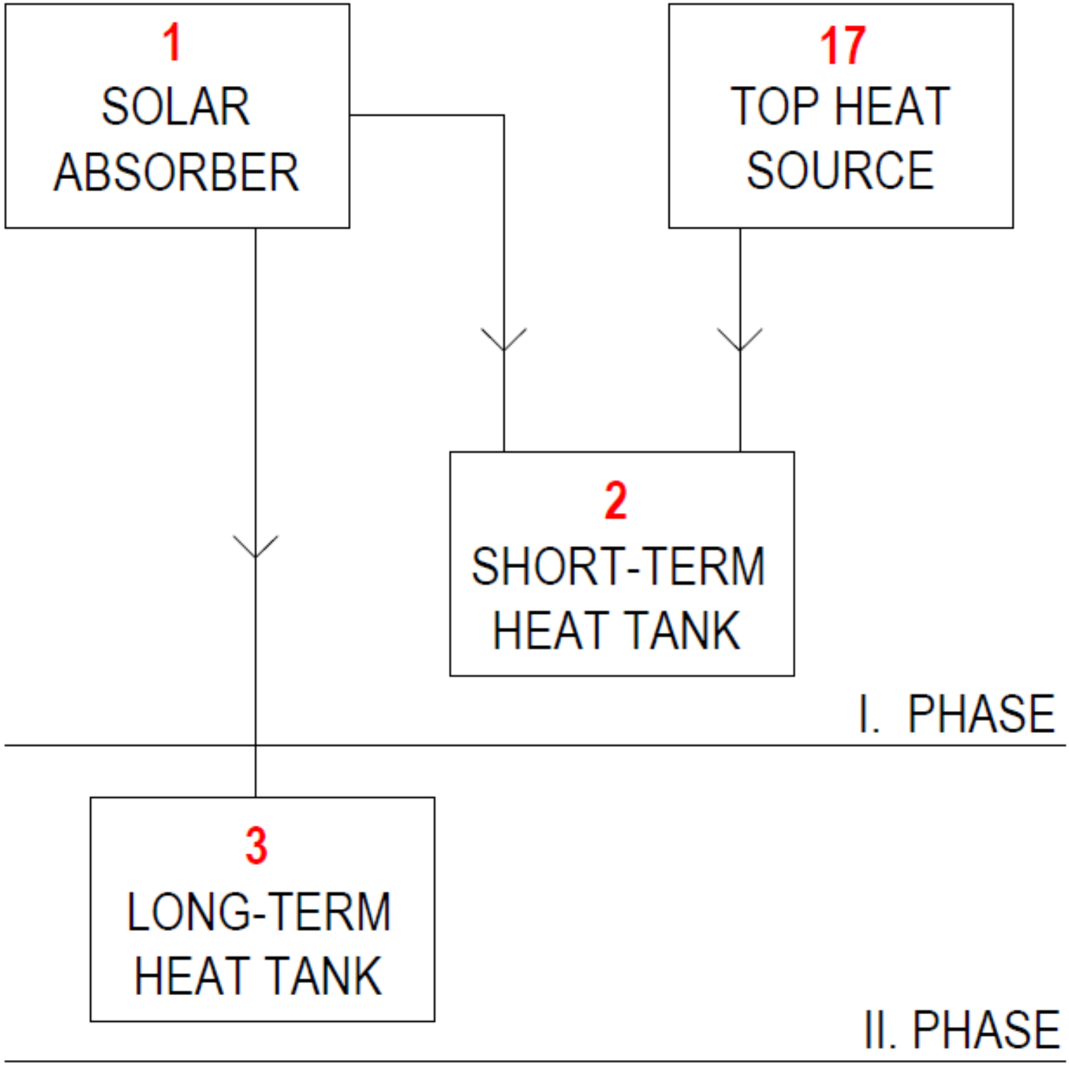
Solar Thermal Energy Storage Operation

The accumulation of heat from solar absorbers takes place in two phases. In the first phase, the heat is accumulated in at least one short-term heat reservoir “2” based on a liquid, solid, or phase change substance. In the second phase, the heat is accumulated in at least one long-term heat reservoir “3” based on a liquid, a solid, or a change of state. For the phase differentiation of the heat storage, the criterion is the full heat capacity of the short-term heat storage, Figure 7.

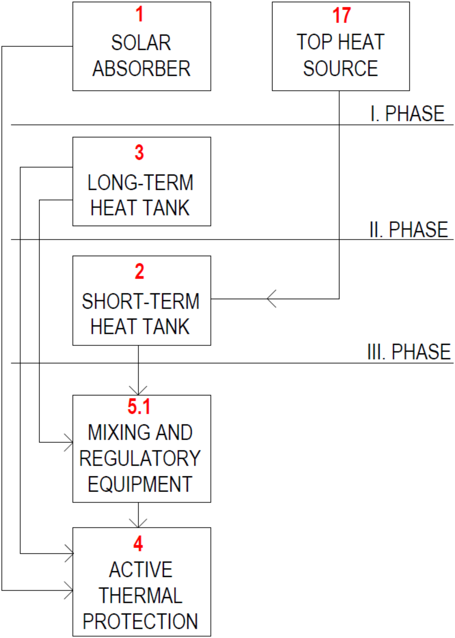
Operation with Active Thermal Protection

Active thermal protection “4” built into the building envelope is carried out by heat or cold distributed to the thermal wall barrier in at least one of three phases. In the first phase, the heat distribution is carried out directly from the solar absorbers “1”. In the second phase, heat or cold distribution is carried out from at least one long-term heat “3” or cold store “8”. In the third phase, the heat distribution is carried out from at least one short-term heat/cool storage tank “2/10”. Alternatively, the distribution of heat and cold to the thermal barrier is carried out by mixing in a mixing and control device “5”, Figure 6 and Figure 8.

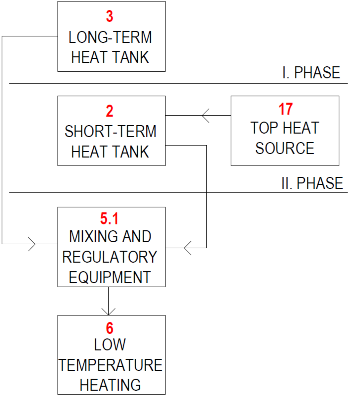
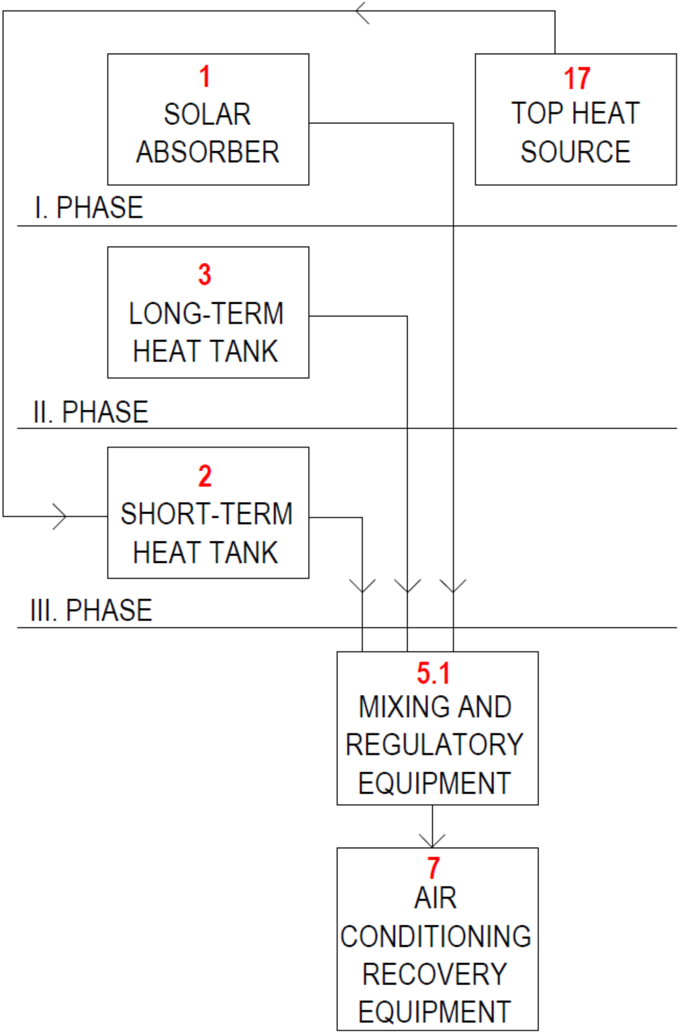
Operation with Low-Temperature Hot-Water Heating

Underfloor, ceiling, or wall heating “6” is carried out by heat distributed to the low-temperature heating system from at least one short-term heat reservoir “2” or from at least one long-term heat reservoir “3” or by mixing the heat transfer medium from both heat reservoirs “5”, Figure 9.

Operation with Hot Air Heating

Hot air heating is accomplished by receiving and/or transferring heat or cooling recovery heat in a heat recovery air handling unit “7” located in the building with preheating/cooling of the air in heat exchangers “3/8” located at a non-freezing depth in the ground. Reheating/recooling of preheated/precooled ventilated air is by means of a heater/cooler located near or directly integrated into the heat recovery air handling unit “7”, Figure 6 and Figure 10.

Operation with Cooling and/or Ventilation

To distribute cold for wall and/or ceiling cooling “11” and/or active thermal protection “4” and/or controlled forced ventilation “7”, the natural temperature of the ground from a non-freezing depth “8” and/or the low temperature of the liquid from a liquid or phase change or solid based cold storage “10” reservoir cooled by a peak cooling source “9” shall be utilized, Figure 11.

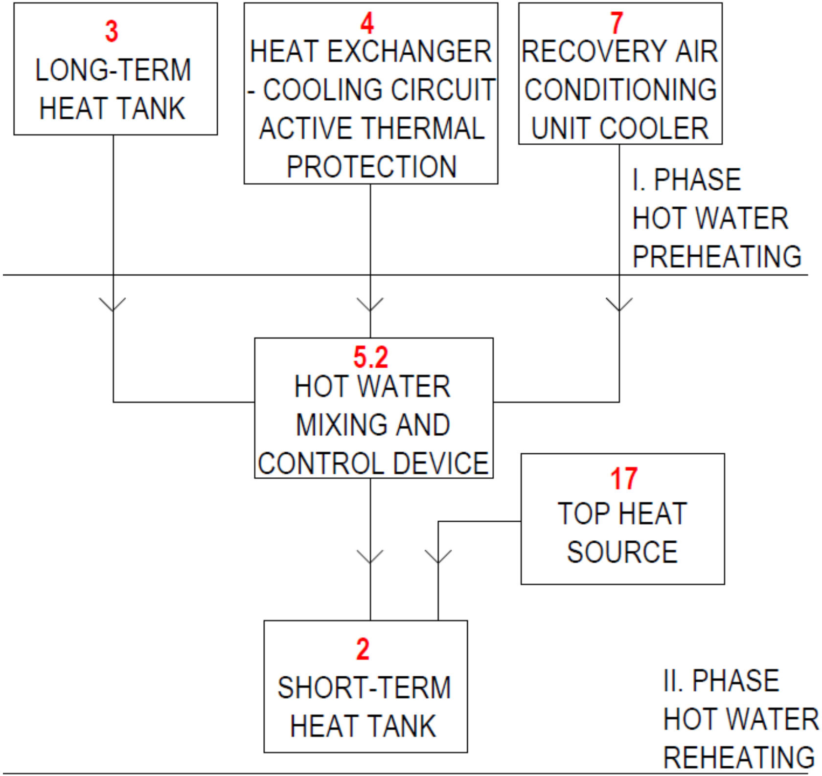
Operation with Preheating and Reheating of Domestic Hot Water

Hot water heating is carried out in two phases. In the first phase, the preheating of the hot water takes place in a long-term liquid “3”, solid or phase change heat storage tank and/or in a heat exchanger “8” used to cool the active thermal protection “4” and/or in the heat sink of the heat recovery air handling unit “7”. In the second phase, the hot water is heated in a short-term heat storage tank “2”, Figure 12.

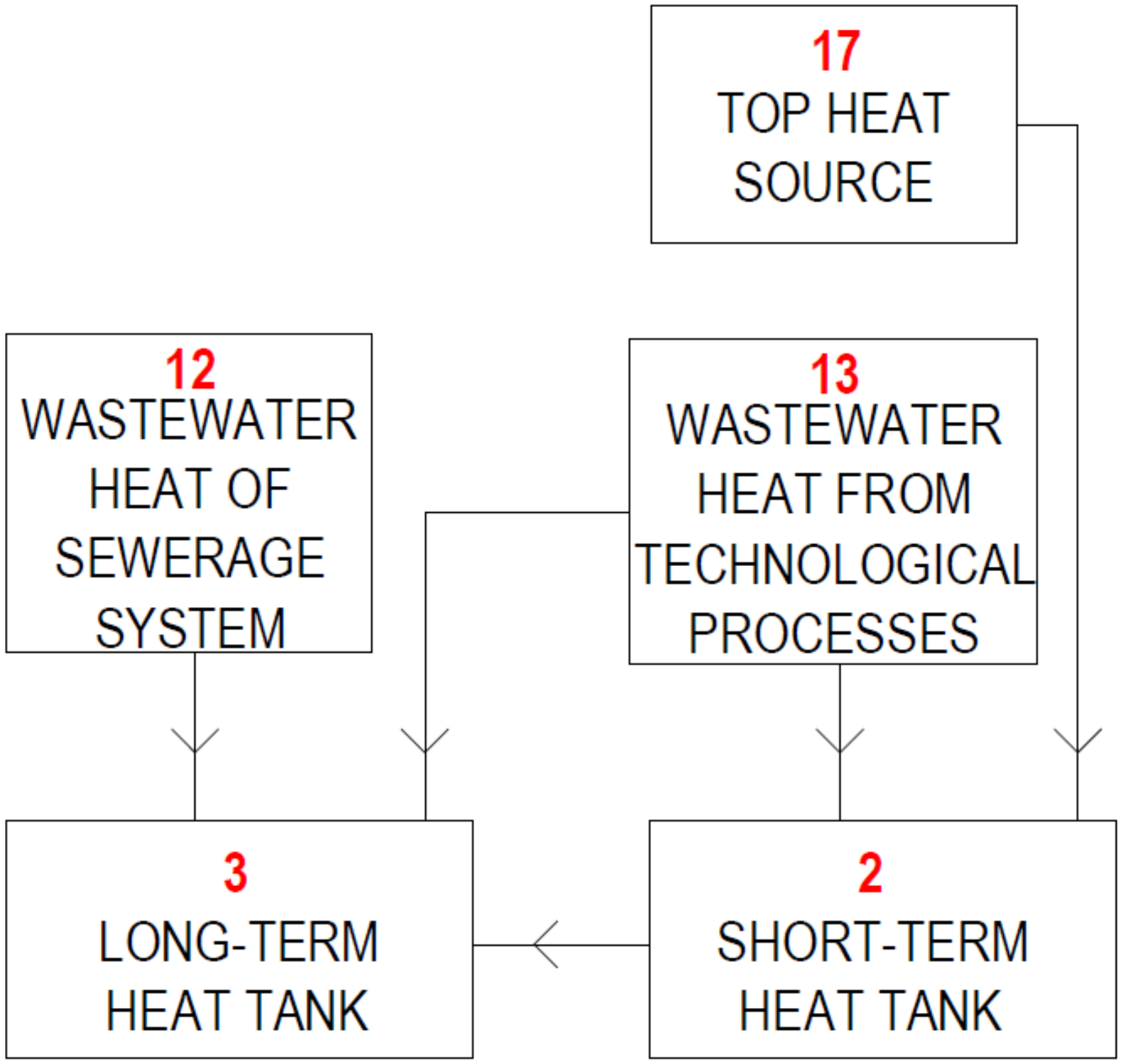
Waste Heat Recovery Operation

The heat from the peak heat source “17” and/or heat recovery “7” and/or waste heat from production and technological processes “12 and 13” is still stored in the short-term heat storage “2”, Figure 13.

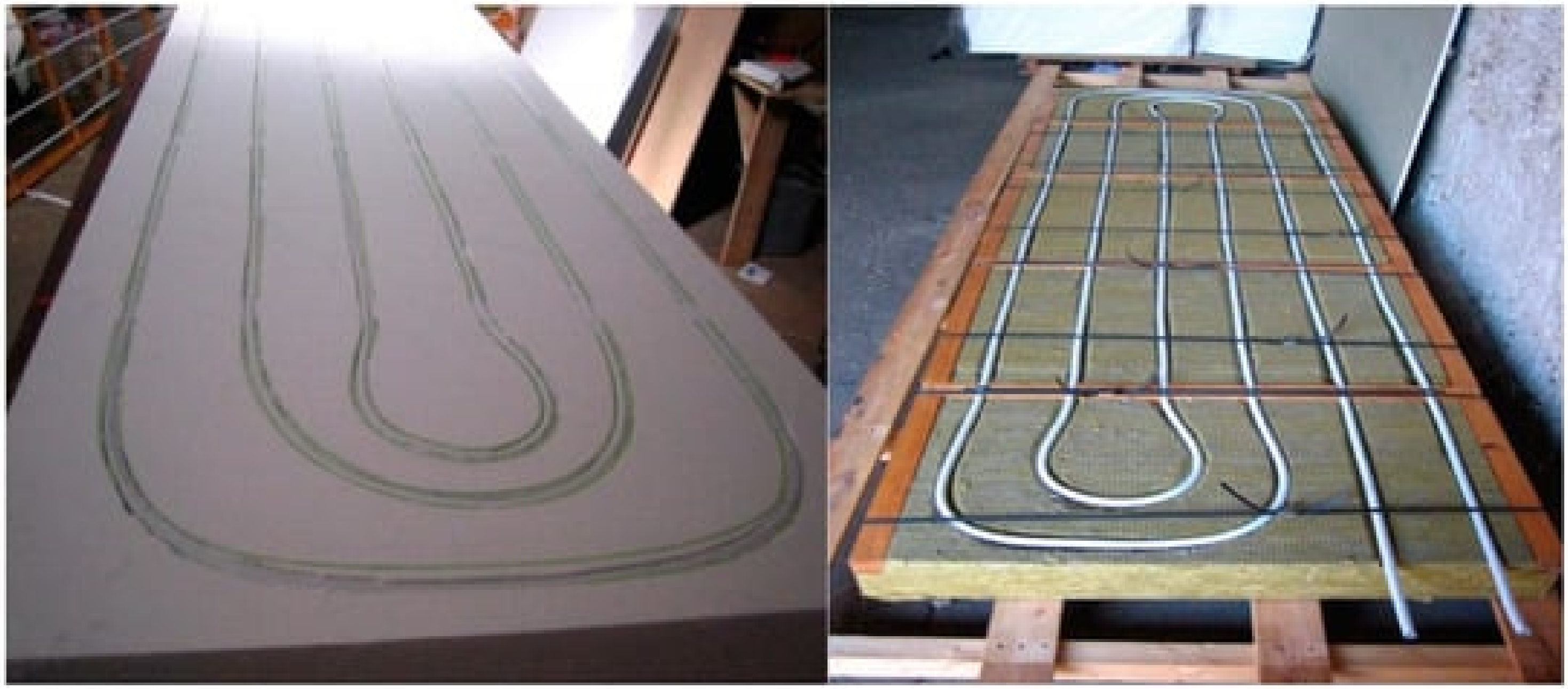
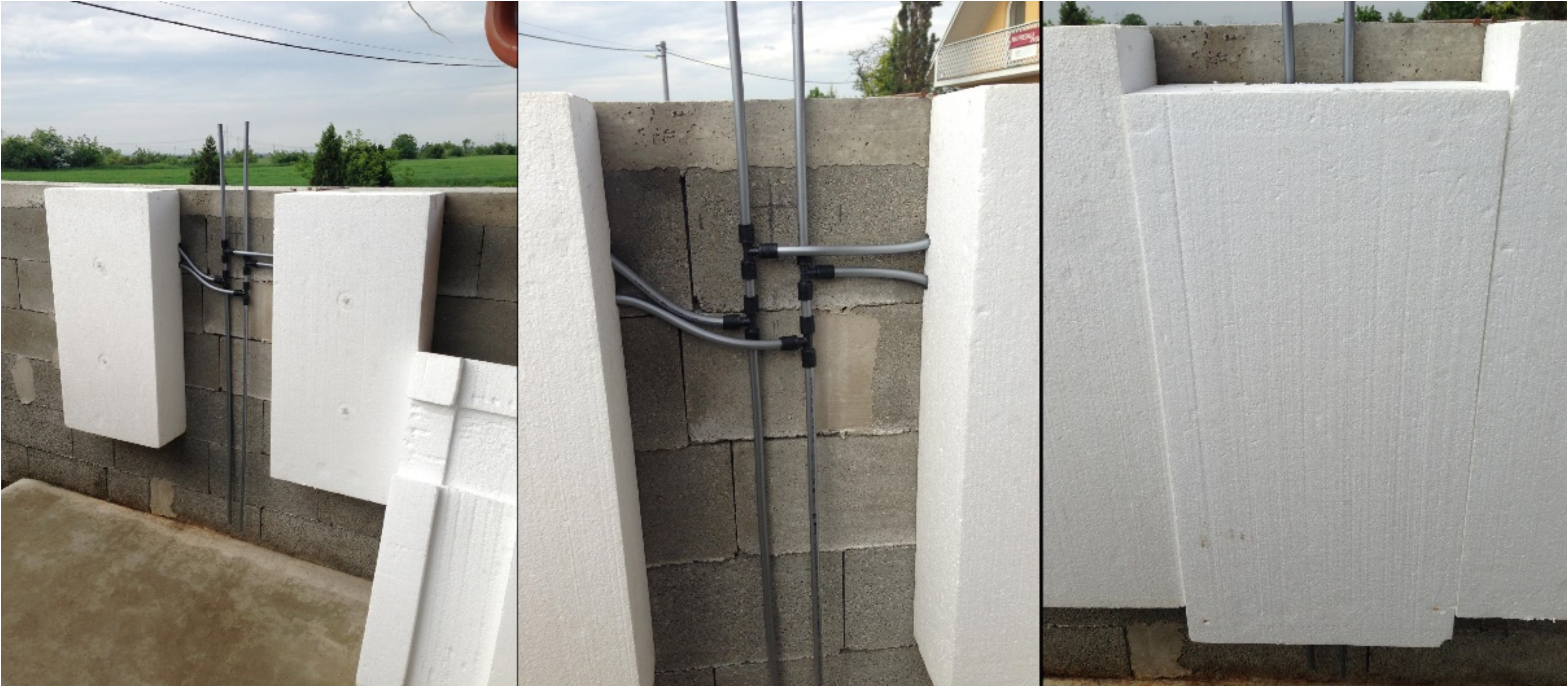
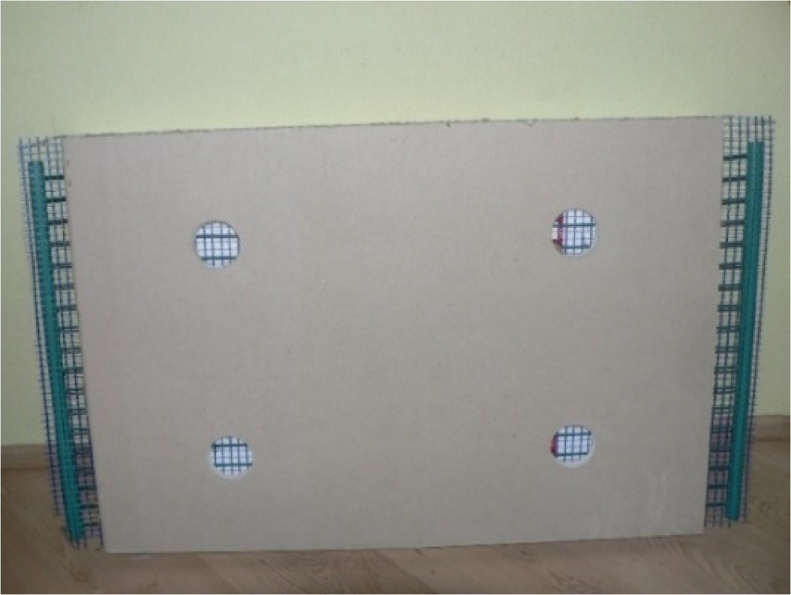
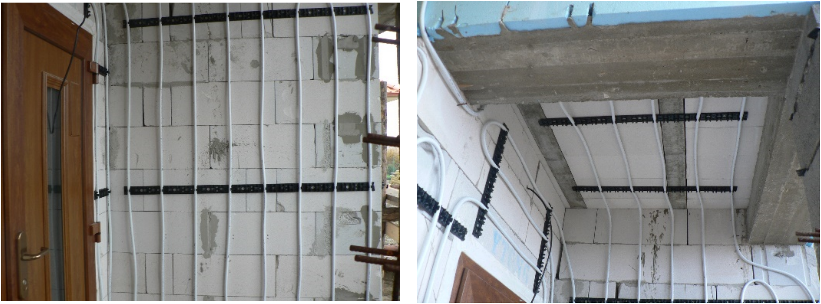
2.2.2. The Development of an Innovative Circuit Panel Solution with Integrated Energy-Active Elements

Active thermal protection in the form of pipe circuits is implemented on brick buildings and also during reconstruction “in a wet way”. The pipes are fixed to the wall surface area plastered, and after the plaster has matured, they are insulated with polystyrene or mineral wool thermal insulation. The thermal insulation can only be glued to avoid damage to the pipes.
This process is time-consuming (waiting for the plaster to dry), difficult (repairing pipes, plastering, and insulation), and lengthy (individual technological procedures). Due to these factors, we created insulation panels with integrated active protection that can be used in place of standard building insulation systems, as shown in Figure 14. Figure 15 shows a photograph of the principle of the contact thermal insulation system with ATP. Variants of the panels with different functions, including the possibility of application from the interior side for heating/cooling, Figure 16, are part of the European patent EP 2 572 057 B1 [20] and utility model SK 5725 Y1 [19].

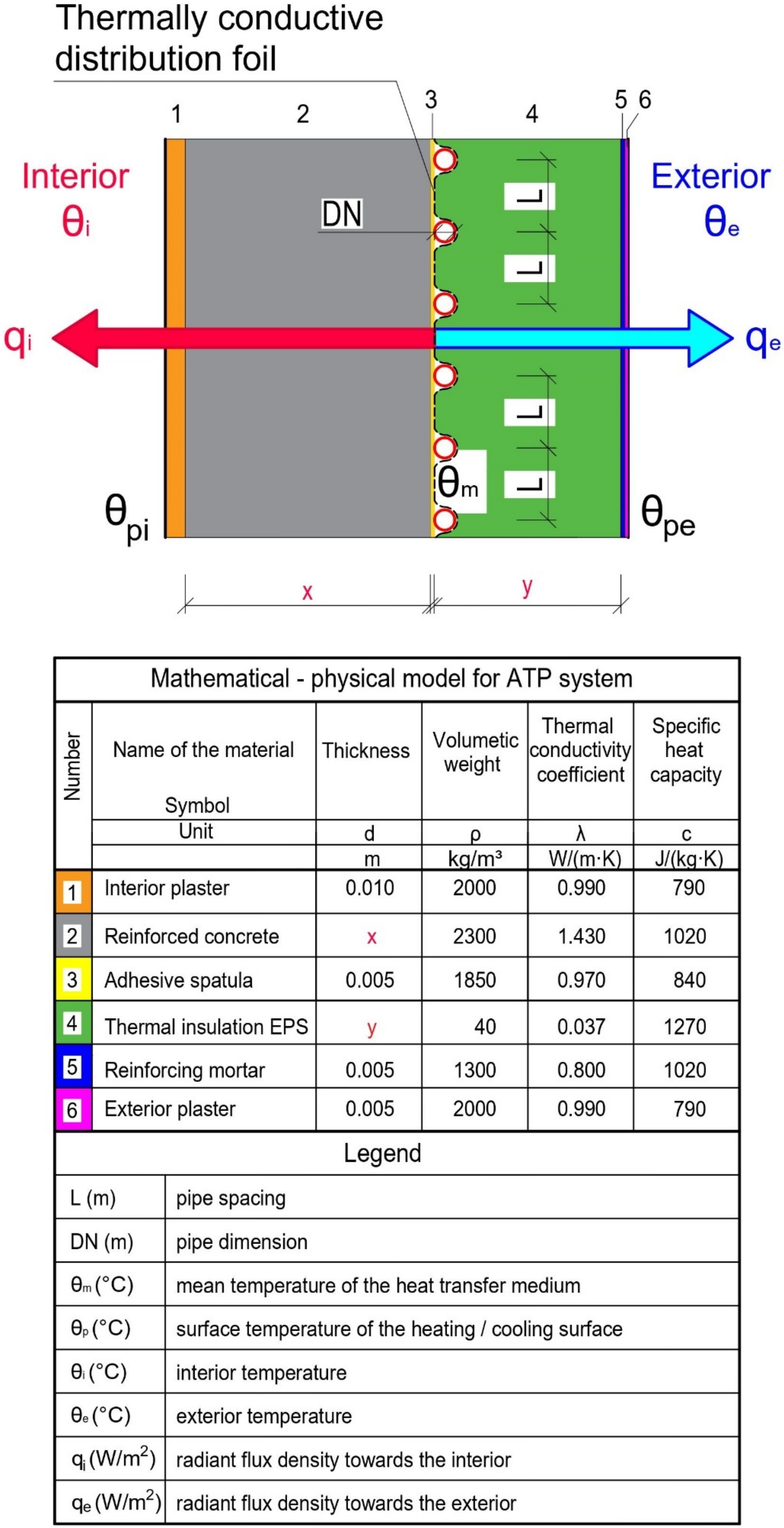
2.2.3. Development of Mathematical-Physical Models of Envelopes with Active Thermal Protection

The heating/cooling performance of thermal insulation panels with integrated active thermal protection depends on several factors, but mainly on the thermal conductivity coefficient of the material of the building structure to be insulated. Figure 17 is a mathematical-physical model for a monolithic reinforced concrete wall with the variables that enter the thermal performance calculation.
The preparation of laboratory measurements of thermal insulation panels with various combinations of energy functions and computer simulations are stages in the research and development of a novel facade system with active thermal protection. The article presents theoretical suppositions, calculation methods, and parametric analyses of three fundamental design options for combined energy wall systems that act as low-temperature radiant heating and high-temperature radiant cooling [23]. In article [24], we describe the theoretical assumptions, calculation procedure, and parametric study to determine the energy potential of an innovative perimeter reinforced concrete panel. We used active thermal protection as a thermal barrier, which was used in constructing the IDA I prototype prefabricated house.

3. Results and Discussion in General

3.1. Results

In general, the results of our long-term research can be divided into theoretical (mathematical-physical models, computer simulations, parametric studies) and practical (a collection of different functional schemes for the connection of combined building-energy systems in various modes of operation, the creation of prototypes of panels with integrated energy-active elements, the design and implementation of experimental buildings, the implementation and evaluation of experimental measurements, utility models, and patent). In this section, we describe:
Parametric study and analysis of the energy potential of active thermal protection in the function of thermal barrier;
The prototype of the prefabricated house IDA I;
The Experimental Family House EB2020.

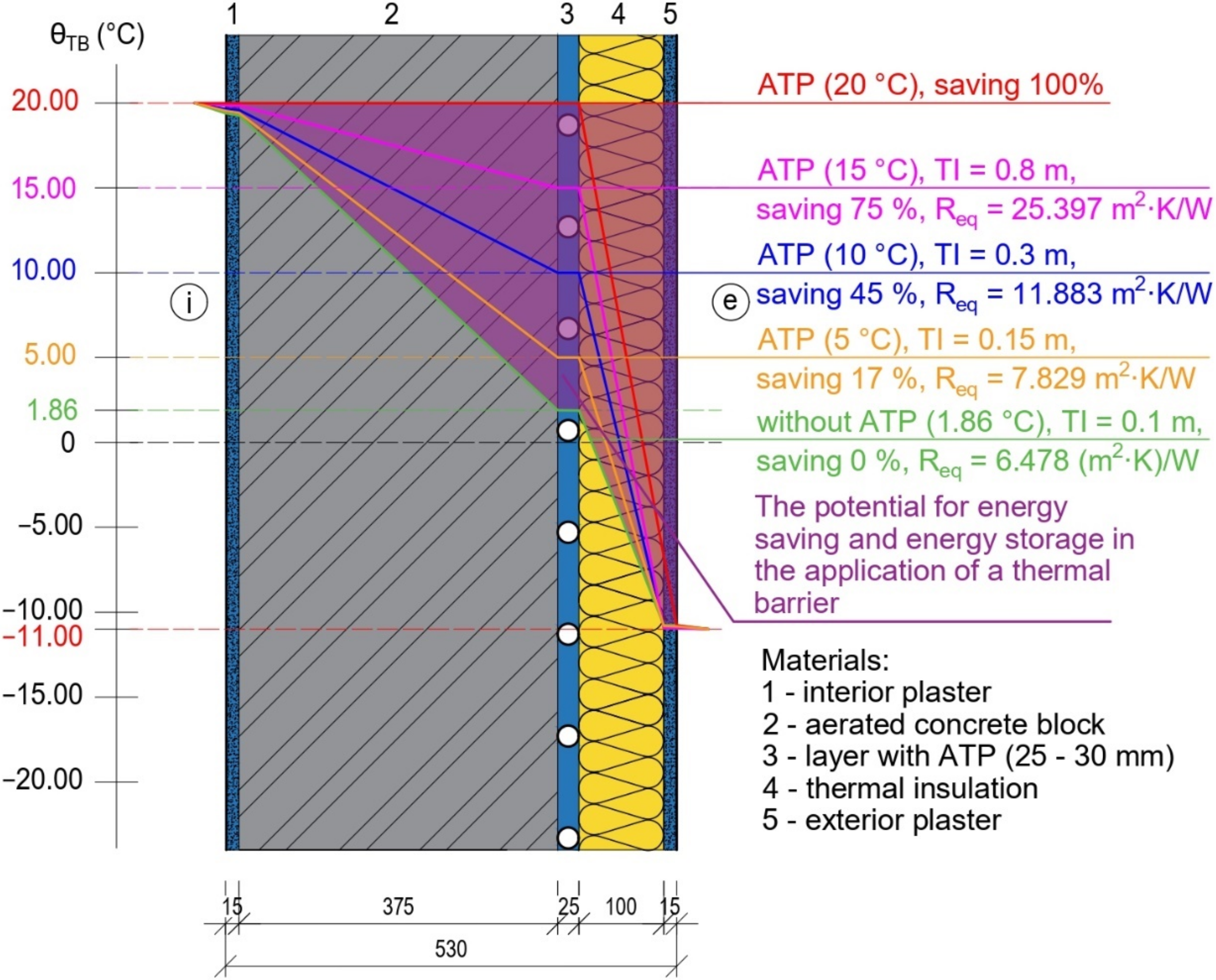
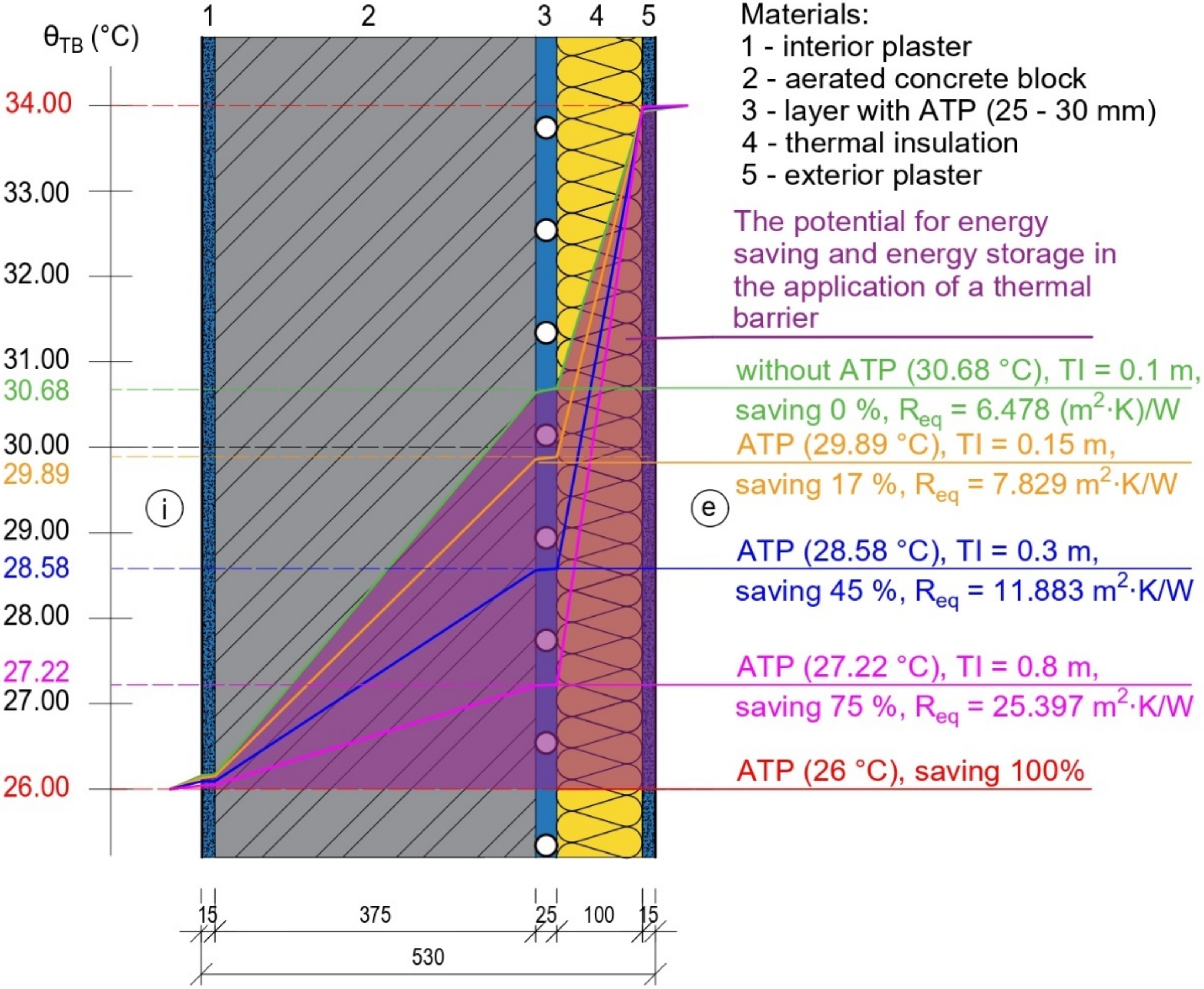
3.1.1. Parametric Study and Analysis of the Energy Potential of Active Thermal Protection in the Function of Thermal Barrier

Figure 18 and Figure 19 show the mathematical-physical models on which we performed a parametric study of active thermal protection as a function of a thermal barrier for a perimeter wall made of aerated concrete blocks. In the design, we investigated the temperature waveforms during the heating period, Figure 18, and during the summer period when cooling is required, Figure 19. The mathematical-physical models show the isotherms for different mean temperatures of the heat transfer medium in the thermal barrier. For example, during the heating season, in Figure 18, the temperature in the structure at the interface between the load-bearing and thermal insulation layers without applying a thermal barrier is θTB = 1.86 °C, with thermal insulation thickness of 100 mm. The application of the thermal barrier modifies the temperature in this layer. For example, a mean temperature of the heat transfer medium of θTB = 10 °C represents an energy saving of 45%, which is the temperature attributable to the structure when thermal insulation of 300 mm thickness is used. Increasing the temperature of the heat transfer fluid in TB also increases the value of the equivalent thermal resistance Req. For example, the thermal resistance value for constructing the perimeter wall in question without active thermal protection is R = 6.478 (m2·K)/W. If we have a thermal barrier in the construction with a mean temperature of the heat transfer medium of 10 °C, the equivalent thermal resistance value will be Req,10 = 11.883 (m2·K)/W. The same physical principle of equivalent thermal resistance applies to cooling, Figure 19.
Both figures show the potential for energy savings and heat/cool accumulation when applying a thermal barrier to the perimeter wall structure in question. For heating, this is an isotherm of +20 °C; for cooling, this is an isotherm of +26 °C. The parametric study results for heating and cooling are given in Table 1 and Table 2. The values of the thermal resistance R, the structure U’s heat transfer coefficient, and the structure’s temperature between the statically load-bearing part of the wall and the thermal insulation layer θTB for different thicknesses of thermal insulation are given. Values for the wall without TB are shown in gray, and values for the alternative with a mean temperature of the heat transfer medium in the TB of +10 °C for heating and +28.58 °C for cooling are shown in green. They represent the equivalent thermal resistance of the building structure with thermal insulation of 300 mm.

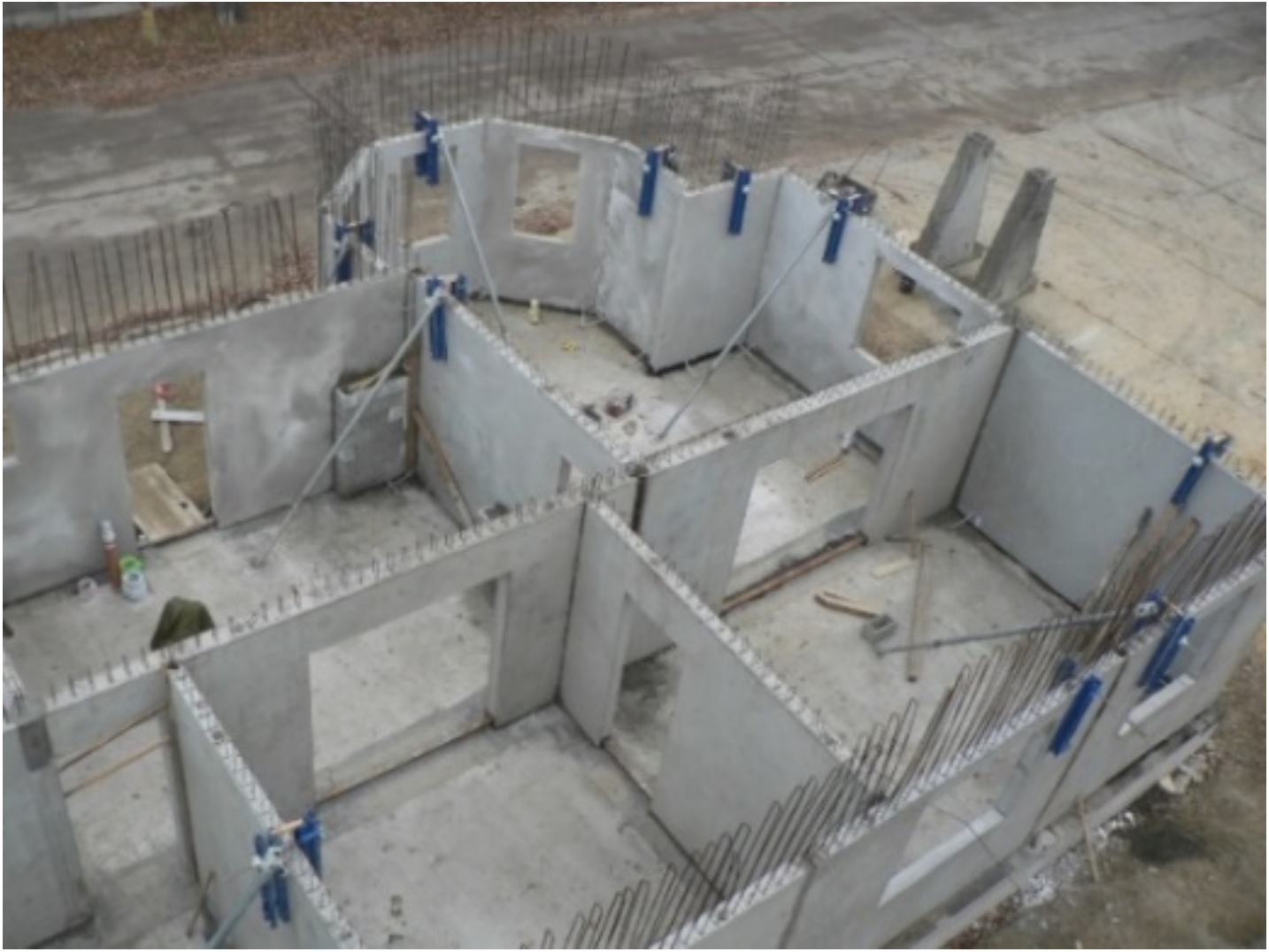
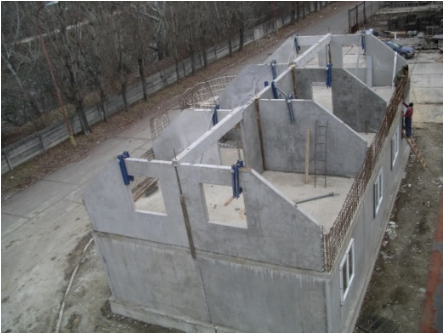
3.1.2. The Prototype of the Prefabricated House IDA I

Based on the fundamental principles of the ISOMAX system [1], we modified and added a high-end heat/cooling source and the end elements of the transfer systems to the prefabricated house IDA I prototype to ensure the heating/ventilation system would operate reliably. The design and construction of the IDA I prefabricated house prototype are discussed in this section as a synthesis of the knowledge discovered through scientific analysis and data transformation.
The panel house IDA I prototype is located in the Paneláreň Vrakuňa, a.s. plant in Bratislava, Slovakia, Figure 20. The building is used as an administration; it has two above-ground floors, and the second floor is an attic [13]. From a structural perspective, it is a prefabricated longitudinal load-bearing system, with load-bearing side walls and one central wall built of reinforced concrete panels. A perpendicular ridge to the front façade is on the gabled roof. There are offices, a restroom, and a hallway on the ground floor. The attic has a hallway, offices, and a bathroom. The layout and construction solution is clearly shown in the photographic documentation in Figure 21, Figure 22, Figure 23 and Figure 24 [13].
Solar energy is absorbed by the energy roof “1” and stored in a medium temperature ground heat storage “3” (GHS-MT), which maintains a temperature range of 30 to 50 °C. This heat source is used for heating, ventilation, and hot water preheating. As a peak heat source “17”, it is suggested that a fireplace with a hot-water heat exchanger and an electric heating insert in the heating water storage tank be used to compensate for heat losses. The heating water storage tank (short-term heat storage) “2” and the ground heat storage tank (long-term heat storage) “3” are both connected to the fireplace hot-water heat exchanger, Figure 25.
The heating system includes underfloor heating circuits “6”, and a thermal barrier “4” is built into the exterior perimeter walls. The peak heat source “17”—a fireplace with a hot water heat exchanger connected to the heating water storage tank “2”, which is furnished with an electric heating insert, is connected to the energy roof “1”, the ground heat storage tank “3”, and the individual circuits via distributors and collectors. Any time and any heat source can provide the required heat for heating, as shown in Figure 25.
The ISOMAX system’s “7” counter-current heat recovery exchanger pipe-in-pipe is intended for both heat recovery and ventilation of the building. It is partly outside the building at a depth of 2 m and partly inside the building in the subsurface heat reservoir at a depth of 1 m below the floor. The air is reheated or cooled using a heat exchanger that is mounted inside the internal supply air duct. The heating water storage tank “2” provides the heat needed to warm the ventilation air. Ground cooling circuits “8”—pipes installed at a depth of about 2 m below ground level outside the building—provide the cooling necessary to cool the ventilation air, Figure 25.
A ground cooling circuit “8” is a piping system constructed of 20 × 2 PP pipes laid at a depth of 2 m below ground level outside the building. This cooling circuit is designed for the cooling of the building. The thermal barrier circuits “4” in the perimeter external walls, which work to reduce the effects of irradiation (preheating the cooled walls in winter), and the heat exchanger in the ductwork, which cools the ventilation air “7”, are both connected to this cooling system via a distributor and collector, Figure 25.
The hot water temperature is prepared in two stages. The first stage involves preheating the water in the ground heat storage tank “3” from around 10 °C to about 25 °C. In the second stage, a trivalent heating water storage tank with an integrated hot water tank “2” is heated to the appropriate temperature of 55 to 60 °C utilizing solar energy, electricity, or hot water heated in a hot water heat exchanger in the fireplace “17,” Figure 25.

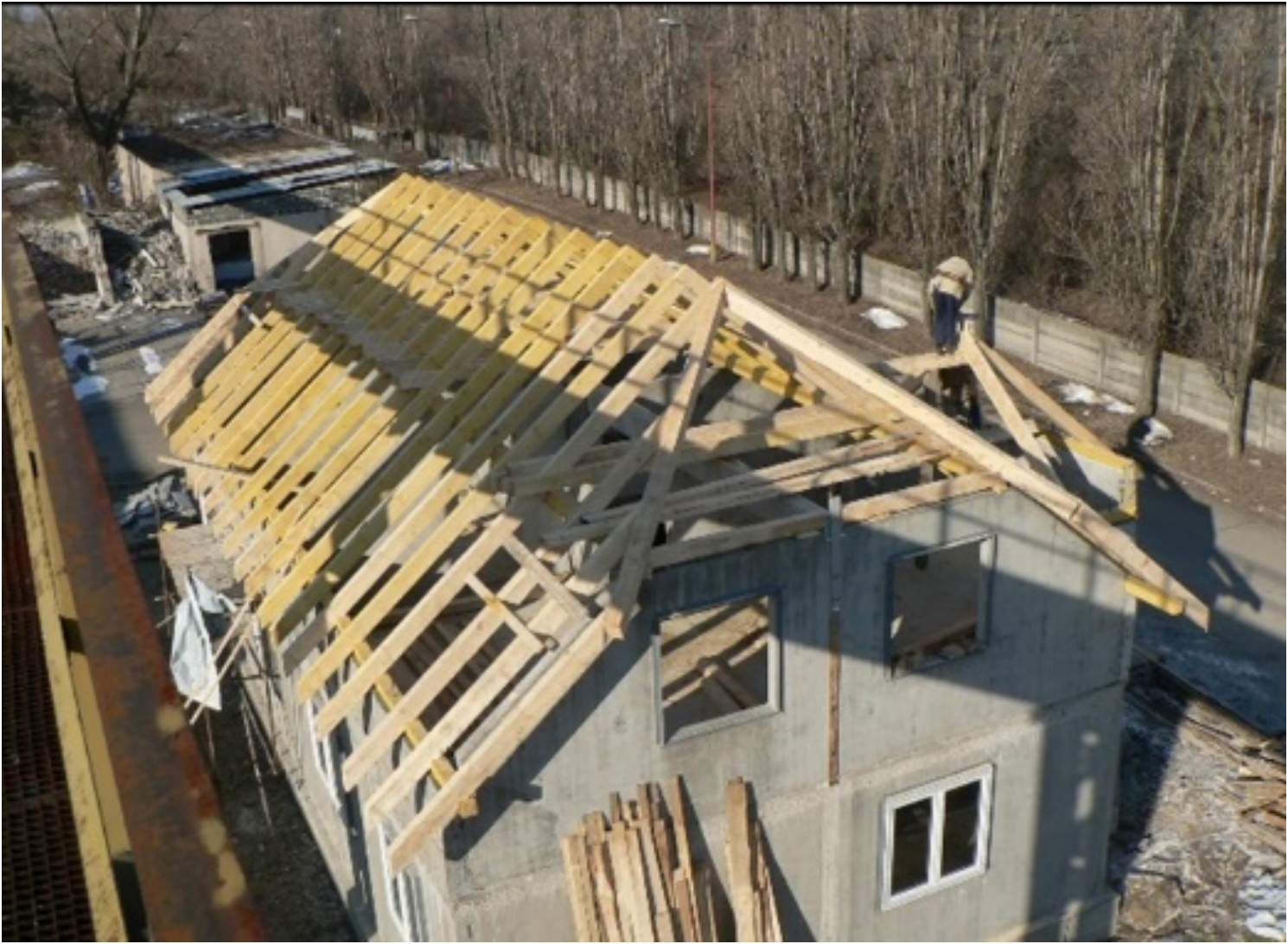
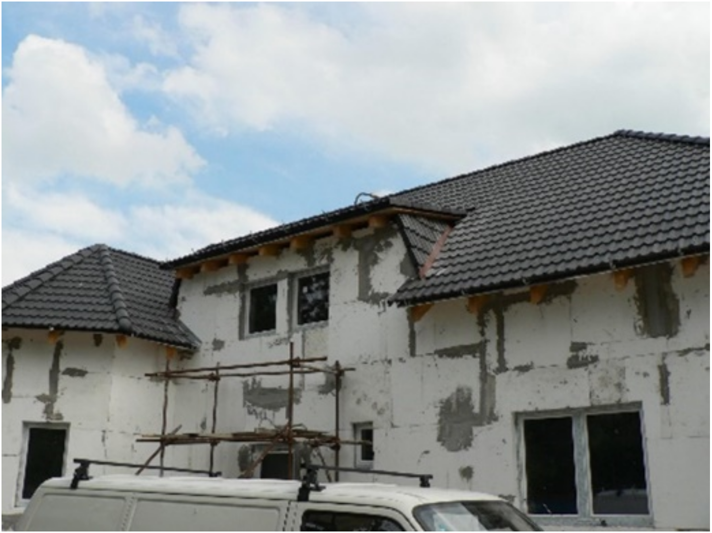
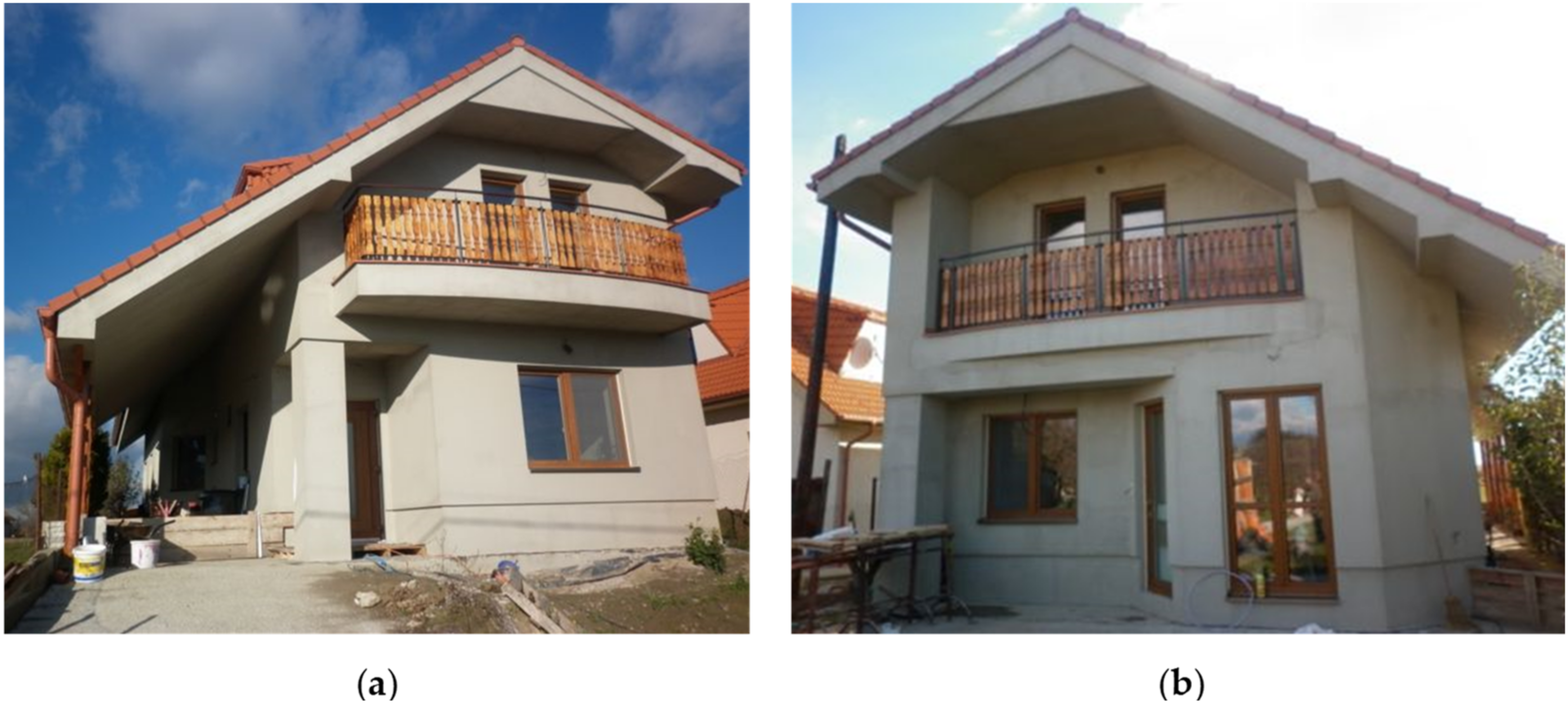
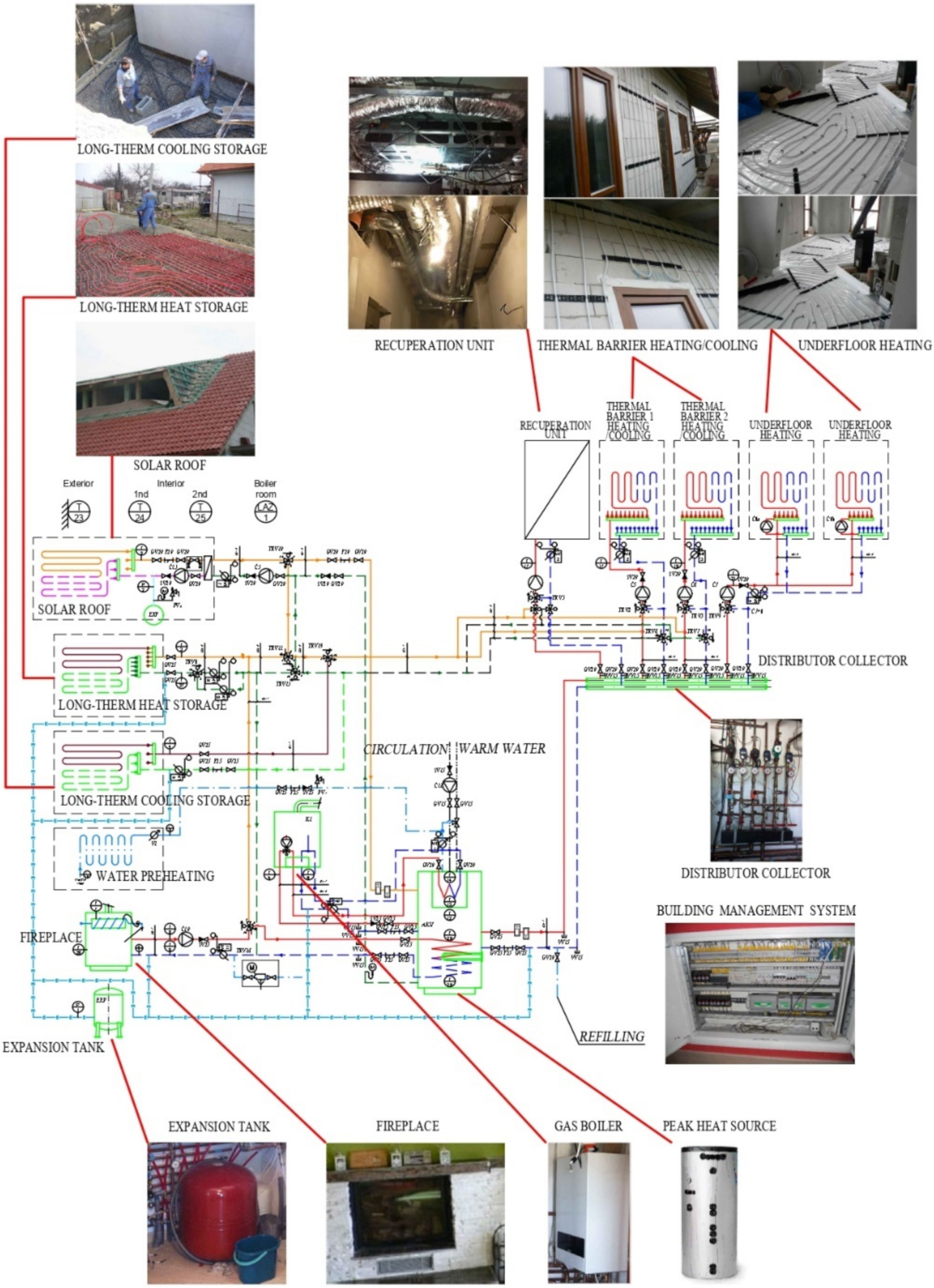
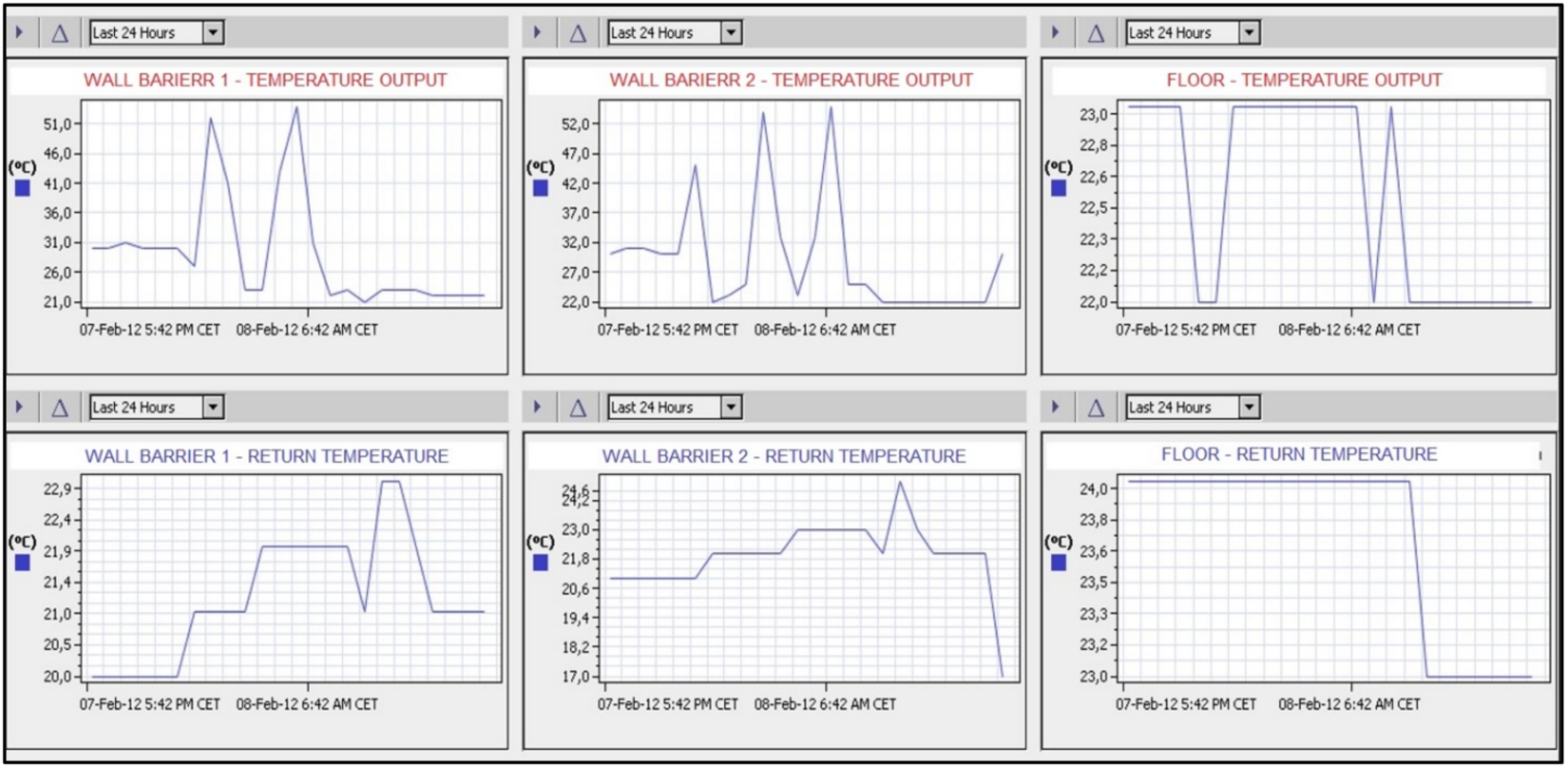
3.1.3. The Experimental Family House EB2020

The synthesis of the knowledge obtained from the scientific analysis was applied by transforming the data into the design, project, implementation, and measurements of the experimental family house EB2020. In [21], we addressed the issue of energy (solar) roofs (ESR) and described the design, implementation, and measurements of the experimental EB2020 family house. Publication [22] focused on the design, implementation, and measurements of a ground heat storage (GHS) on the family house in question. Following on from previous publications, we focus more on active thermal protection in this article. In Section 3.1.1, we described the parametric study and analysis of the energy potential of active thermal protection as a thermal barrier for the perimeter walls of the experimental family house EB2020.
The experimental house called EB2020 is in the village of Tomášov, about 25 km from Bratislava. It is a family house with two floors. On the first floor is an entrance hall, living room with a kitchen, bathroom, and guest room. There is a hallway, three bedrooms, and a bathroom on the second floor. Figure 26a,b view the experimental house from the street and the garden. The perimeter walls are made of aerated concrete blocks of 375 mm thickness, layers with active thermal protection of 25 to 30 mm thickness, thermal insulation of 100 mm thickness, and are plastered on the exterior and interior with plaster of 15 mm thickness.
Active thermal protection is a dynamic process that, in combined building-energy systems, in structures with integrated energy-active elements, depending on the design and material composition of the building envelope, can serve for heating, cooling, thermal barrier, heat/cooling storage, and other energy functions. The active thermal barrier piping is mainly made of plastic pipes placed between the load-bearing part of the building structure and the thermal insulation in the mortar bed, Figure 18 and Figure 19. The piping on the experimental house EB2020 is fixed with plastic battens, Figure 27.
In Figure 28, we present a simplified principal diagram of the combined building-energy systems of the EB2020 experimental house with peak heat sources. To better illustrate the individual energy systems and the overall technical design of the experimental house, we also provide photographs.
In December 2011, the system was put into operation with the use of ATP and underfloor heating (UH), with the temporary use of a low-temperature gas boiler and a hot-water fireplace insert as heat sources. In the 2012/2013 heating season, the heat was also partially supplied to the ATP from the ground source heat storage (GHS). In the summer season, the ATP was operated in the wall cooling function. The source of cooling is plastic pipe circuits located in the ground at a non-freezing depth around the house’s foundation.
The aim of the experimental measurements was a comprehensive evaluation of the system, focusing on the energy and economic aspects, evaluation of the environmental impact, and measurement of the internal environment of the building. The system had to be compared with another operation to draw relevant conclusions. The system was therefore tested in different operations—with and without using ATP. Different inlet temperatures of the working substance to the ATP (thermal barrier) and to the underfloor heating were set to find the optimum energy system use. Comparing different energy system operations in one building is more efficient than measuring different operations in multiple buildings. A single building has the same design and technical boundary conditions, the same number, and occupants’ behavior. The first objective of the long-term measurements was to determine whether operating the energy system with active thermal protection in the thermal barrier and wall heating function makes sense. The ATP in the experimental house EB2020 consists of 20 circuits connected via two circulators. In the diagram in Figure 28, the branches are labeled as “thermal barrier 1” and “thermal barrier 2”.
According to the diagram in Figure 28, the heat produced by the solar energy-energy roof (ESR) is stored in a ground heat storage (GHS), while it is also capable of being placed in a combination storage vessel when the circumstances are right. A heat exchanger is attached between the primary side, where the glycol-based antifreeze is circulated, and the secondary side. A fireplace insert, which serves as the heat source for the storage vessel, can also provide heat to the ground heat storage tank. A low-temperature gas boiler serves as an additional heat source for the storage vessel. The storage tank also has a 6 kW electric heating insert. The storage tank provides low-temperature radiant floor heating. The ground source heat store or the storage tank may be used to provide ATP.
The energy system’s control, regulation, and monitoring were implemented via an Internet connection. This made it possible to control how the power system operated and to alter the input parameters as necessary. It was possible to start or stop the operation of ATP1, ATP2, or floor heating using an Internet connection to set the desired input temperature, or to start the system with the epithermal control by setting the required indoor temperature. Figure 29 shows that the measured data were saved on the server and accessible at all times. The program allowed for the display of the heat given in GJ to ATP1, ATP2, and underfloor heating at any time (last 24 h, week, month, year, or it was possible to enter a specific period). Additionally, the output and flow rate of ATP1, ATP2, and underfloor heating could all be seen.

3.2. Discussion in General

The heating/cooling performance of thermal insulation panels with integrated active thermal protection depends on several factors, but mainly on the thermal conductivity coefficient of the material of the building structure to be insulated. Figure 17 is a mathematical-physical model for a monolithic reinforced concrete wall with the variables that enter the thermal performance calculation. For the parametric study, we created computational software in MS Excel.
The calculation was made for the heating season. Boundary conditions: thickness of reinforced concrete bearing part of the panel bpanel = 150 mm, thickness of thermal insulation bTI = 200 mm, outer dimension of the ATP pipe d = 15 mm, distance between pipes L = 0.150 m, heat transfer coefficient towards the interior hp = 10 W/(m2·K) (according to EN 15377-1 [25] and STN 73 0540-2+Z1+Z2 [26]), heat transfer coefficient towards the exterior he = 7 W/(m2·K) (according to STN 73 0540-2+Z1+Z2, [26]). In the simplified calculation relations, the same wall mass temperature in front of and behind the pipe was considered in calculating the average design temperature in the pipe axis and the average surface temperature in accordance with [27,28,29]. The outside air temperature θe = −11 °C, the inside air temperature θi = 20 °C, and the average temperature of the working medium in the ATP pipe θm = 30 °C were considered. The results of the parametric study were compared for the perimeter system with direct heating (VARIANT I), semi-accumulation heating (TABS system—VARIANT II), and the system with ATP (accumulation heating—VARIANT III), Figure 30.
For thermal insulation in the thickness range of 50 to 100 mm, the heat flux to the interior qi (W/m2) increases while the heat loss qe (W/m2) decreases rapidly. For thicknesses above 100 mm, the effect of adding more insulation becomes relatively small. This is true regardless of the thickness of the concrete core, which has almost no effect on the heat flux. On the other hand, the effect of pipe spacing on heating performance is evident; despite the small effect on the heat flux to the interior, increasing the thickness of the concrete, and hence the inertia of the wall, can reduce the energy demand for heating [25]. The storage capacity, which is expressed as a time constant, can range from approximately 2.5 to almost 8 h for a system with a pipe embedded in a solid concrete core [30]. For example, N. Aste et al. [31] report that in Milan, Italy, the energy demand for high inertia walls can be up to 10% lower than for low inertia walls. S.A. Al-Sanea, M.F. Zedan, and S.N. Al-Hussain [32] calculated for the climate of Riyadh, Saudi Arabia, a reduction in energy demand for increasing wall thickness and a heating energy saving of up to 35% due to thermal mass optimization. Other studies [33,34,35] highlight the importance of concrete thickness for the thermal dynamics of buildings, which must be considered when designing new construction, renovation, or control system.
Based on the analysis of the results of the parametric study of the energy potential of the individual technical solutions of the envelope panels with integrated energy-active elements, it can be concluded that the increase in heat losses due to the location of the tubes in the structure closer to the exterior for VARIANT II, semi-accumulation heating (TABS system), and VARIANT III, accumulation heating, in relation to VARIANT I, direct heating, negligible, below 1% of the total delivered heat flux, Figure 30.
The direct heat flux to the heated room is 89.17% for direct heating, VARIANT I, 73.36% for semi-accumulation heating (TABS system), VARIANT II and 58.46% for accumulation heating, VARIANT III of the total delivered heat flux, Figure 30.
For simplicity, VARIANT I does not consider heat accumulation for the panel. For the panel design (TABS system), VARIANT II represents 14.84% and VARIANT III up to 29.86% heat accumulation of the total delivered heat flux, Figure 30.
Variants II and III appear promising in heat/cool accumulation with an assumption of lower energy demand (at least 10%) than for low inertia walls.
The potential application of the work lies in the presented variants of combined building-energy systems of buildings using renewable energy sources. Compared to fossil fuel-based heat/cooling sources, these technical solutions meet the conditions of energy security, self-sufficiency, and carbon neutrality of European Union buildings. Perimeter panels with integrated energy-active elements represent a progressive alternative to traditional energy systems for heating, cooling, and domestic hot water preparation, in particular, due to their multifunctional application capability from the use of both source and end elements of energy systems.
We plan to extend our research to date with dynamic computer simulations to optimize the design and composition of panels with integrated energy-active elements to build experimental buildings. Moreover, we intend to optimize the design of energy (solar) roofs (ESR), ground heat storage (GHS), active thermal protection (ATP), and their cooperation in different modes of operation of energy systems, with an emphasis on the use of renewable energy sources (RES) and waste heat.

4. Conclusions

Based on the theoretical analysis in the field of energy solar roofs (ESR), ground heat storages (GHS), and active thermal protection (ATP), as well as the research carried out on the IDA I prototype prefabricated house and the experimental family house EB2020, the following statements can be made:
The application of an energy (solar) roof (ESR) requires lower investment costs than conventional solar collectors, but experimental measurements have shown that the energy gain and the achieved outlet temperatures of the working fluid are significantly lower. To increase the ESR efficiency, applying a dark-colored roof covering is important and installing more circuits with a suitable distribution according to cardinal directions is important.
The use of ESR for low-temperature heating or supply of active thermal protection can only be implemented with a suitable heat storage solution. For hot water production, the ESR can only be used for preheating. The ESR could also be used as a collector for a heat pump, which would serve for heating, domestic hot water preparation, and cooling.
Heat accumulation in a conventional house slab foundation as a ground heat storage (GHS) is limited only to the application of active thermal protection in a thermal barrier (TB) function. It is insufficient for heating and domestic hot water. Heat accumulation from ESR and peak heat sources is recommended in large-capacity water storage tanks or in storage tanks with the change of state.
The use of ATP in wall heating and cooling is of practical significance only in building constructions with a high accumulation capacity on the inside in front of the ATP tubes, i.e., high bulk density, thermal conductivity, and thermal capacity, e.g., reinforced concrete.
Building structures that have a high thermal resistance in front of the ATP pipes are only suitable for the thermal barrier function. Parametric studies predict such structures to achieve high equivalent thermal resistance at relatively low mean temperatures of the heat transfer medium. For example, +10 to +15 °C represents a design with thermal insulation of 300 to 800 mm, see Table 1 in Section 3.1.1.
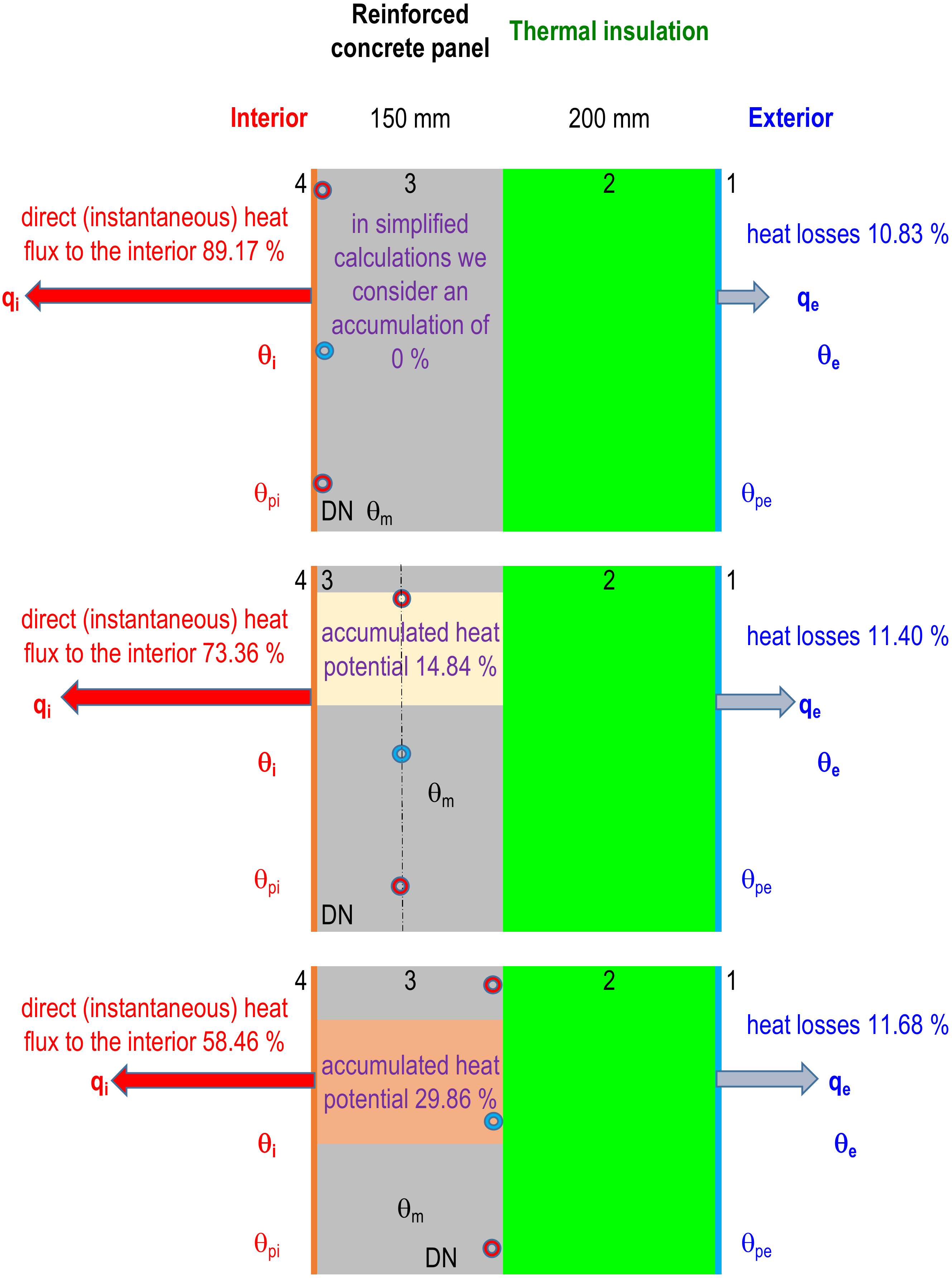
Based on the analysis of the parametric study results of the energy potential of individual technical solutions of reinforced concrete envelope panels with integrated energy active elements in Section 3.2., it can be concluded that the increase in heat loss due to the location of the tubes in the structure closer to the exterior is negligible for VARIANT II, semi-accumulation heating (TABS system), and VARIANT III, accumulation heating, compared to VARIANT I, direct heating, below 1% of the total delivered heat flux, Figure 30. The direct heat flux to the heated room is 89.17% for direct heating, VARIANT I, 73.36% for semi-accumulation heating (TABS system), VARIANT II and 58.46% for accumulation heating, VARIANT III of the total delivered heat flux, Figure 30. For simplicity, VARIANT I does not consider heat accumulation for the panel. For the panel design (TABS system), VARIANT II represents 14.84% and VARIANT III up to 29.86% heat accumulation of the total delivered heat flux, Figure 30. Variants II and III appear promising in heat/cool accumulation with an assumption of lower energy demand (at least 10%) than for low inertia walls.
Variants in how energy systems operate represent energy-safe and environmentally friendly technical solutions that need to be adapted and optimized case-by-case based on all input requirements.
Based on the design, project, and implementation of the prototype of the prefabricated house IDA I and the experimental house EB2020, we have created variants of functional measurement and control schemes for the interconnection of all energy systems, which, in synergy with the building control system optimize the mode of operation in buildings using combined building-energy systems. We have also defined operational strategies for the individual energy systems, Section 3.1. These solutions are analyzed in detail in utility model SK 5749 Y1 (Kalús: author of the technical solution) [17], 2011.
Based on energy analysis and the technological process of ISOMAX system panels production, we proposed for the prototype of prefabricated house IDA I an innovative composition of the perimeter panel with thermal barrier and proposed other possible variants of self-supporting thermal insulation panels with active heat transfer control of different structures with different energy functions (thermal barrier, heating, cooling, heat accumulation, heat recovery, collection of solar energy, and energy of the surrounding environment) based on liquid and gaseous heat transfer agent. The above variants and their possible applications are described in the utility model SK 5729 Y1 (Kalús: author of the technical solution) [18], 2011.
Active thermal protection in masonry buildings is implemented by fixing pipes to the perimeter walls and then plastering. After the covering plaster has cured, the walls are thermally insulated. At present, the method of implementing active thermal protection in masonry buildings is costly and time-consuming. For these reasons, we have developed a prototype thermal insulation panels for systems with active heat transfer control implemented on-site as a conventional contact insulation system. These are thermal insulation panels with integrated pipes. The technical solution and different variants of these thermal insulation panels are described in utility model SK 2725 Y1 (Kalús: author of the technical solution) [19], 2011 and European patent EP 2 572 057 B1 (Kalús: author of the technical solution) [20], 2014.

Author Contributions

Conceptualization, D.K. (Daniel Kalús), P.J., D.K. (Daniela Koudelková), M.K., V.M. and M.S.; methodology, D.K. (Daniel Kalús), P.J., D.K. (Daniela Koudelková) and M.K.; validation, D.K. (Daniel Kalús), D.K. (Daniela Koudelková) and M.K.; formal analysis, D.K. (Daniel Kalús); investigation, D.K. (Daniel Kalús), P.J., D.K. (Daniela Koudelková) and M.K.; resources, D.K. (Daniel Kalús), P.J., D.K. (Daniela Koudelková), M.K. and V.M.; data curation, D.K. (Daniel Kalús), P.J., D.K. (Daniela Koudelková), M.K., V.M. and M.S.; writing—original draft preparation, D.K. (Daniel Kalús), P.J., D.K. (Daniela Koudelková), M.K., V.M. and M.S.; writing—review and editing, D.K. (Daniel Kalús), P.J., D.K. (Daniela Koudelková), M.K., V.M. and M.S. All authors have read and agreed to the published version of the manuscript.

Funding

The publication of this work was financially supported by EHBconsulting s.r.o. At the same time, we express our sincere thanks to the private investor Ing. Tomáš Ircha, who significantly supported the research in the field of combined building and energy systems.

Institutional Review Board Statement

Not applicable.

Informed Consent Statement

Not applicable.

Data Availability Statement

Not applicable.

Acknowledgments

This research was supported by the Ministry of Education, Science, Research and Sport of the Slovak Republic (grant VEGA 1/0304/21). This research was also supported by the Ministry of Education, Science, Research, and Sport of the Slovak Republic (grant KEGA 005STU-4/2021).

Conflicts of Interest

The authors declare no conflict of interest.

References

  1. Available online: http://www.isomax-terrasol.eu/home.html (accessed on 17 August 2022).
  2. Available online: https://www.rehau.com/sk-sk (accessed on 17 August 2022).
  3. Available online: https://www.rieder.cc/us/ (accessed on 17 August 2022).
  4. Li, Y.; Ding, D.; Liu, C.; Wang, C. A pixel-based approach to estimation of solar energy potential on building roofs. Energy Build. 2016, 129, 563–573. [Google Scholar] [CrossRef]
  5. Michael, J.J.; Selvarasan, I. Economic analysis and environmental impact of flat plate roof mounted solar energy systems. Sol. Energy 2017, 142, 159–170. [Google Scholar] [CrossRef]
  6. Walch, A.; Castello, R.; Mohajeri, N.; Scartezzini, J.L. Big data mining for the estimation of hourly rooftop photovoltaic potential and its uncertainty. Appl. Energy 2020, 262, 114404. [Google Scholar] [CrossRef]
  7. Lazzarotto, A. Developments in Ground Heat Storage Modeling. Ph.D. Dissertation, KTH Royal Institute of Technology, Stockholm, Sweden, 2015. [Google Scholar]
  8. Haq, H.M.; Hiltunen, E. An inquiry of ground heat storage: Analysis of experimental measurements and optimization of system’s performance. Appl. Therm. Eng. 2019, 148, 10–21. [Google Scholar] [CrossRef]
  9. Sun, T.; Yang, L.; Jin, L.; Luo, Z.; Zhang, Y.; Liu, Y.; Wang, Z. A novel solar-assisted ground-source heat pump (SAGSHP) with seasonal heat-storage and heat cascade utilization: Field test and performance analysis. Sol. Energy 2020, 201, 362–372. [Google Scholar] [CrossRef]
  10. Li, A.; Xu, X.; Sun, Y. A study on pipe-embedded wall integrated with ground source-coupled heat exchanger for enhanced building energy efficiency in diverse climate regions. Energy Build. 2016, 121, 139–151. [Google Scholar] [CrossRef]
  11. Kisilewicz, T.; Fedorczak-Cisak, M.; Barkanyi, T. Active thermal insulation as an element limiting heat loss through external walls. Energy Build. 2019, 205, 109541. [Google Scholar] [CrossRef]
  12. Iffa, E.; Hun, D.; Salonvaara, M.; Shrestha, S.; Lapsa, M. Performance evaluation of a dynamic wall integrated with active insulation and thermal energy storage systems. J. Energy Storage 2022, 46, 103815. [Google Scholar] [CrossRef]
  13. Kalús, D. The Contract for Work HZ 04–309–05—Design of a Passive House Using Solar and Geothermic Energy; K–TZB SvF STU: Bratislava, Slovakia, 2006. [Google Scholar]
  14. Cvíčela, M. Analysis of Wall Energy Systems. Ph.D. Dissertation, Faculty of Civil Engineering, Slovak University of Technology in Bratislava, Bratislava, Slovakia, 2011. [Google Scholar]
  15. Kalús, D. The Contract for Work HZ PG73/2011—Experimental Measurements, Analysis, and Determination of the Optimal Rate of Use of Renewable Energy Sources on a Prototype of a Family House EB2020 with Nearly Zero Energy Demand; K-TZB SvF STU: Bratislava, Slovakia, 2011–2013. [Google Scholar]
  16. Janík, P. Optimization of Energy Systems with Long-Term Heat Accumulation. Ph.D. Dissertation, Faculty of Civil Engineering, Slovak University of Technology in Bratislava, Bratislava, Slovakia, 2013. [Google Scholar]
  17. Available online: https://wbr.indprop.gov.sk/WebRegistre/UzitkovyVzor/Detail/5027-2010 (accessed on 17 August 2022).
  18. Available online: https://wbr.indprop.gov.sk/WebRegistre/UzitkovyVzor/Detail/5030-2010 (accessed on 17 August 2022).
  19. Available online: https://wbr.indprop.gov.sk/WebRegistre/UzitkovyVzor/Detail/5031-2010 (accessed on 17 August 2022).
  20. Available online: https://patents.google.com/patent/WO2011146025A1/und (accessed on 17 August 2022).
  21. Kalús, D.; Janík, P.; Kubica, M. Experimental house EB2020—Research and experimental measurements of an energy roof. Energy Build. 2021, 248, 111172. [Google Scholar] [CrossRef]
  22. Kalús, D.; Janík, P.; Koudelková, D.; Mučková, V.; Sokol, M. Contribution to research on ground heat storages as part of building energy systems using RES. Energy Build. 2022, 267, 112125. [Google Scholar] [CrossRef]
  23. Kalús, D.; Gašparík, J.; Janík, P.; Kubica, M.; Šťastný, P. Innovative building technology implemented into facades with active thermal protection. Sustainability 2021, 13, 4438. [Google Scholar] [CrossRef]
  24. Kalús, D.; Koudelková, D.; Mučková, V.; Sokol, M.; Kurčová, M. Contribution to the Research and Development of Innovative Building Components with Embedded Energy-Active Elements. Coatings 2022, 12, 1021. [Google Scholar] [CrossRef]
  25. Šimko, M.; Krajčík, M.; Šikula, O.; Šimko, P.; Kalús, D. Insulation panels for active control of heat transfer in walls operated as space heating or as a thermal barrier: Numerical simulations and experiments. Energy Build. 2018, 158, 135–146. [Google Scholar] [CrossRef]
  26. Standard STN 73 0540-2+Z1+Z2; Thermal Protection of Buildings. Thermal Performance of Buildings and Components. Part 2: Functional requirements. Slovenský Ústav Technickej Normalizácie: Bratislava, Slovakia, 2019.
  27. Babiak, J.; Olesen, B.W.; Petras, D. Low Temperature Heating and High Temperature Cooling. Embedded Water Based Surface Heating and Cooling Systems; Rakennusten Pintalaemmitys Ja-Jaeaehdytys. Rakenteisiin Upotetut Vesikiertoiset Pintalaemmitys-Ja Jaeaehdytysjaerjestelmaet. Available online: https://www.osti.gov/etdeweb/biblio/1030138 (accessed on 5 August 2022).
  28. Petráš, D. Nízkoteplotní Vytápění a Obnovitelné Zdroje Energie; Vydavateľstvo JAGA Group: Bratislava, Slovakia, 2008; 216p, ISBN 978-80-8076-069-4. [Google Scholar]
  29. Petráš, D.; Kalús, D.; Koudelková, D. Vykurovacie Sústavy, Cvičenie a Ateliérová Tvorba; STU: Bratislava, Slovakia, 2012; ISBN 978-80-227-3795-1. [Google Scholar]
  30. Ning, B.; Schiavon, S.; Bauman, F.S. A novel classification scheme for design and control of radiant system based on thermal response time. Energy Build. 2017, 137, 38–45. [Google Scholar] [CrossRef]
  31. Aste, N.; Angelotti, A.; Buzzetti, M. The influence of the external walls thermal inertia on the energy performance of well insulated buildings. Energy Build. 2009, 41, 1181–1187. [Google Scholar] [CrossRef]
  32. Al-Sanea, S.A.; Zedan, M.F.; Al-Hussain, S.N. Effect of thermal mass on performance of insulated building walls and the concept of energy savings potential. Appl. Energy 2012, 89, 430–442. [Google Scholar] [CrossRef]
  33. Schmelas, M.; Feldmann, T.; Wellnitz, P.; Bollin, E. Adaptive predictive control of thermo-active building systems (TABS) based on a multiple regression algorithm: First practical test. Energy Build. 2016, 129, 367–377. [Google Scholar] [CrossRef]
  34. Nemethova, E.; Petras, D.; Krajcik, M. Indoor environment in a high-rise building with lightweight envelope and thermally active ceiling. In Proceedings of the 12th REHVA World Congress (CLIMA 2016), Aalborg, Denmark, 22–25 May 2016; Volume 22, p. 2016. [Google Scholar]
  35. Široký, J.; Oldewurtel, F.; Cigler, J.; Prívara, S. Experimental analysis of model predictive control for an energy efficient building heating system. Appl. Energy 2011, 88, 3079–3087. [Google Scholar] [CrossRef]
Figure 1. Overview of source elements of energy systems and end elements of energy systems of combined building-energy systems.
Applsci 12 09313 g001
Figure 2. Engelmann Sensostar2 compact heat meters [15,16].
Applsci 12 09313 g002
Figure 3. Measuring and recording control panel installed in the experimental house EB2020 [15,16].
Applsci 12 09313 g003
Figure 4. Testo 845 Infrared Thermometer [15,16].
Applsci 12 09313 g004
Figure 5. MobIR M4 portable infrared camera [15,16].
Applsci 12 09313 g005
Figure 6. Variants of power equipment cooperate in different modes of operation.
Applsci 12 09313 g006
Figure 7. Functional diagram of the solar thermal energy storage operation [17].
Applsci 12 09313 g007
Figure 8. Functional diagram of the operation with active thermal protection [17].
Applsci 12 09313 g008
Figure 9. Functional diagram of the combined building-energy system in low-temperature heating mode [17].
Applsci 12 09313 g009
Figure 10. Functional diagram of the combined building-energy system in hot-air heating mode [17].
Applsci 12 09313 g010
Figure 11. Functional wiring diagram of a combined building-energy system in cooling and/or ventilation mode [17].
Applsci 12 09313 g011
Figure 12. Functional diagram of the combined building-energy system in preheating and hot water reheating mode [17].
Applsci 12 09313 g012
Figure 13. Functional diagram of the combined building-energy system in waste heat recovery mode [17].
Applsci 12 09313 g013
Figure 14. View of prototypes of insulation panels with integrated active thermal protection, on the left made of polystyrene, on the right of mineral wool. [Author: Kalús].
Applsci 12 09313 g014
Figure 15. The principle of the contact thermal insulation system with ATP. [Author: Kalús].
Applsci 12 09313 g015
Figure 16. View of a prototype interior panel with capillary mat application for heating/cooling. [Author: Kalús].
Applsci 12 09313 g016
Figure 17. Mathematical-physical model of a perimeter wall with a thermal insulation panel with integrated active thermal protection.
Applsci 12 09313 g017
Figure 18. Mathematical-physical model of construction with isotherms for heating.
Applsci 12 09313 g018
Figure 19. Mathematical-physical model of construction with isotherms for cooling.
Applsci 12 09313 g019
Figure 20. Location of the prototype of the prefabricated house IDA I. within Bratislava, Slovak Republic. (https://www.google.com/maps, accessed on 17 August 2022).
Applsci 12 09313 g020
Figure 21. Completion of the ground floor assembly. (Photo archive: Kalús, D.) [13].
Applsci 12 09313 g021
Figure 22. Mounting the attic (Photo archive: Kalús, D.) [13].
Applsci 12 09313 g022
Figure 23. View of the realization of the wooden truss. (Photo archive: Kalús, D.) [13].
Applsci 12 09313 g023
Figure 24. View of the implementation of the insulation of the perimeter panels. (Photo archive: Kalús, D.) [13].
Applsci 12 09313 g024
Figure 25. Simplified wiring diagram of the technical solution of the energy systems of the IDA I prefabricated house prototype [13]. 1—solar absorber (energy roof, solar collector, etc.), 2—short-term heat storage, 3—long-term heat storage, 4—active thermal protection circuits (building structure with an internal heat source), 5—mixing and control equipment, 6—low-temperature heating circuits, 7—heat recovery ventilation equipment, 8—cooling circuits located in the ground outside the building, 9—peak cooling source, 10—short-term cold storage, 11—high-temperature cooling circuits, 12—waste heat from the drainage system, 13—waste heat from the technological process, 14—electricity generation equipment (photovoltaics, wind power plant, etc.), 15—building control system, 16—batteries for storing electricity, 17—top heat source. (Note: The description of the numerical items is identical to the devices in Figure 6 and in Section 2.2.1).
Applsci 12 09313 g025
Figure 26. Experimental house EB2020: (a) View from the street; (b) view from the garden. [Author: Kalús].
Applsci 12 09313 g026
Figure 27. Placing pipes of active thermal protection on the facade. [Author: Kalús].
Applsci 12 09313 g027
Figure 28. Wiring diagram of the technical solution of the energy systems of the experimental house EB2020. [Author: Kalús].
Applsci 12 09313 g028
Figure 29. Display the working substance’s temperature in the supply (red) and return (blue) pipes from ATP1, ATP2, and underfloor heating for the last 24 h [15].
Applsci 12 09313 g029
Figure 30. Heat flux analysis for the investigated variants of mathematical-physical perimeter reinforced concrete panels models. qi—heat flow towards the interior (W/m2), qe—heat flow towards the exterior (W/m2), θi—internal calculation temperature (°C), θe—outdoor calculation temperature (°C), θpi—interior surface temperature (°C), θpe—exterior surface temperature (°C), 1–4—layer number. [Author: Kalús].
Applsci 12 09313 g030
Table 1. Parameters during heating.
dTIext (m)0.0750.1000.1250.1500.1750.2000.2500.3000.400
U (W/(m2·K))0.1670.1500.1370.1250.1150.1070.0930.0830.068
R (m2·K/W)5.8026.4787.1547.8298.5059.18110.53211.88314.586
θTB (°C)−0.1901.8603.5404.9306.1007.1108.73010.00011.830
dTIext (m)0.5000.6000.7000.8000.9001.0001.5002.0003.000
U (W/(m2·K))0.0570.050.0440.0390.0350.0320.0220.0170.012
R (m2·K/W)17.28919.99122.69425.39728.09930.80244.31657.82984.856
θTB (°C)13.09014.0214.7315.2815.7416.1117.2917.9218.58
Table 2. Parameters during cooling.
dTIext (m)0.0750.1000.1250.1500.1750.2000.2500.3000.400
U (W/(m2·K))0.1670.1500.1370.1250.1150.1070.0930.0830.068
R (m2·K/W)5.8026.4787.1547.8298.5059.18110.53211.88314.586
θTB (°C)31.2130.6830.2529.8929.5929.3328.9128.5828.11
dTIext (m)0.5000.6000.7000.8000.9001.0001.5002.0003.000
U (W/(m2·K))0.0570.050.0440.0390.0350.0320.0220.0170.012
R (m2·K/W)17.28919.99122.69425.39728.09930.80244.31657.82984.856
θTB (°C)27.7827.5427.3627.2227.1027.0026.7026.5426.37
Publisher’s Note: MDPI stays neutral with regard to jurisdictional claims in published maps and institutional affiliations.

