Article

Semianalytical Lower-Bound Limit Analysis of Domes and Vaults

Department of Engineering, University of Campania “L. Vanvitelli”, 81031 Aversa, Italy
*
Author to whom correspondence should be addressed.
These authors contributed equally to this work.
Appl. Sci. 2022, 12(18), 9155; https://doi.org/10.3390/app12189155
Submission received: 2 August 2022 / Revised: 29 August 2022 / Accepted: 3 September 2022 / Published: 13 September 2022
(This article belongs to the Special Issue Advances in Non-destructive Diagnosis of Masonry)

Abstract

:

Featured Application

The possible application of the work is in the forecast of the stability of masonry or concrete structures. The result is very useful in addressing the restoration and interpreting the results of the experimental monitoring of the structures during their lifetime. The nonlinear analysis conducted by means of the upper-bound theorem of the limit design allows for evaluating the response to different randomly variable and unknown load paths giving the overall safety factor. In this way, the real-life behavior of the structures can be addressed by practitioners that must monitor and restore the art structures.

Abstract

The calculation of the collapse load of spherical domes is addressed using a semianalytical approach under the hypothesis of small displacements and perfect plasticity. The procedure is based on the numerical approximation of the self-stress that represents the projection of the balance equilibrium null space on a finite dimensional manifold. The so-obtained self-equilibrated stress span is superimposed onto a finite-element linear elastic solution to the prescribed loads yielding to the statically admissible set accordingly to Melan’s theorem. The compatibility of the stress with the constitutive law of the material was enforced using a linearized limit domain in terms of generalized stress, namely, axial force and bending moment along the local spherical curvilinear coordinates. The procedure was tested with reference to numerical and experimental data from the literature, confirming the accuracy of the proposed method. A comparison with the literature confirms that the buckling load was much greater than the two plastic collapse loads calculated through the proposed procedure and reported in the quoted literature.

1. Introduction

Spherical-shell safety to applied loads is related to the loss of equilibrium consequent to geometric- or constitutive-limit attainment. The geometric limit trespass consists of the buckling or snapping phenomenon insurgence, while constitutive limits involve the plastic collapse of the structure. The two phenomena are connected, since plastic collapse occurs when the buckling limit is attained because of the great stress level consequent to large deflections arising when the structure buckles. Analogously, the buckling occurs when, due to plastic collapse, large deflections appear. Combined limit evaluation implies coupled formulation that can generally be resolved only through a path following analysis. In the following, we refers to limit analysis only in order to obtain the collapse loads and mechanisms under the hypotheses of small displacement plasticity. To calculate the limit load for the plastic collapse of the structures, limit analysis results in one of the tools that have received major interest. A complete survey and the proposal of a finite-element approach for domes and shells using cylindrical hinges between element interfaces where the dissipation is localized are in [1]. Recently, static analysis has received renewed interest in the masonry structure framework due to the trust-line method and limit equilibrium application [2,3,4,5]. Limit analysis is used for the safety assessment of concrete domes and achesfor large structures, as shown in [6,7,8]. In particular, the authors in [9,10] investigated concrete vessels’ composite structures considering collapse and buckling load evaluation. In [11], an application of the kinematic method was presented for a first-order assessment strategy of the structure safety. Size effects and the corresponding influence on the structural limit behavior is addressed differently by [12] considering dome stability under spreading supports. Experimental and analytical results using limit analysis were presented in [13], where the results were compared with those obtained by the experimental campaign reported in [14]. In particular, the authors in [13] highlighted that the collapse load of concrete caps is calculated through crack-line development balance using an analytical formulation that applies the upper-bound kinematic approach of limit analysis. Moreover, the collapse formula was compared to the experimental campaign from [14] and to the buckling load calculated in [15]; the accuracy of the proposed limit analysis is addressed. In particular, the authors in [13] reported that the collapse load from the experimental campaign was predicted by the limit analysis rather than buckling theoretical formulas. In [16,17,18], a more comprehensive study can be found.
In the present paper, we discuss an application of the semianalytical formulation that presents the lower-bound theorem of the limit analysis to assess dome collapse load on the basis of the self-equilibrated solution of the balance equations. The present work applies the procedure that is reported in [16,18] to slender concrete caps studied by [14] with the scope of comparing the proposed semianalytical formulation to the experiments and the theoretical formulation from [13]. The limit analysis lower-bound proposed formulation is rather general, can deal with any structure for which an analytical balance equation exists, and can be solved numerically for calculating the self-equilibrated stress set. The load can vary in time both monotonically and randomly, provided that the time variation is slow enough to prevent inertial effects. The procedure recalls Melan’s theorem; hence, it requires knowledge of a linearly elastic solution due to the applied loads. Such an elastic solution was obtained through a homemade APDL routine written for finite-element program ANSYS© Multiphysics (ANSYS Inc., Canonsburg, PA, USA). The use of a finite element to obtain the elastic solution allows for freeing the particular solution from the knowledge of actual elastic stress. The compatibility condition was formulated according to Melan’s theorem in the stress space [19], and the eigensolution was discretized to be handled in a numerical optimization program that finds the load multiplier. The results from the proposed formulation showed good agreement with the experiments by Vandepitte and Lagae [14], and with the analogous calculation presented in [13,20] that had been obtained with a somewhat different application of the limit analysis formulated in terms of collapse lines and the upper-bound theorem.
This work starts with reporting a brief outline of the general formulation. First, the spherical domes equilibrium equations are recalled, and the eigensolution, i.e., the solution of the homogeneous equation, is introduced in discretized form. In the subsequent section, the constitutive and compatibility equations of the unreinforced concrete that constitute the cap material are described, and the limit domain is derived in linearized form. Furthermore, the case study and the linear elastic solution derived using finite-element linear analysis are presented. Lastly, the optimization program used to obtain the collapse load multiplier is described, and the results are discussed. The result depends on the parameters of the eigensolution, which were the design variables that represent the Melan’s residuals of the structure at the incoming collapse.

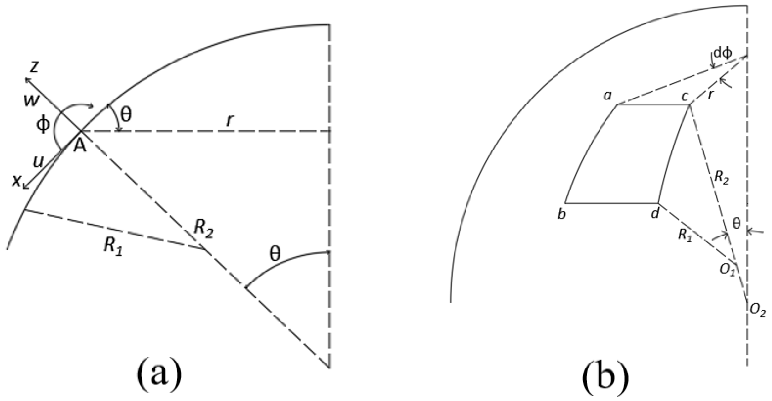
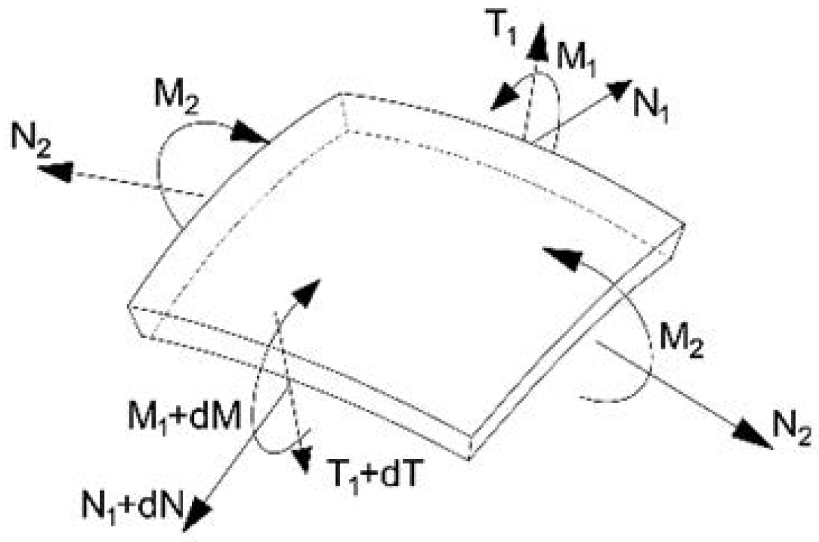
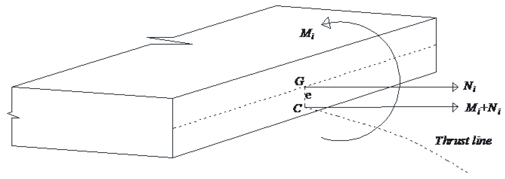
2. Equilibrium and Self-Equilibrium of Domes

This section briefly recalls a spherical shell equilibrium equation; the complete treatment can be found in [21]. The formulation used generalized stress as mechanical parameters; hence, the stress is described through internal forces N, T, and M that are the resultant components, axial, and shear forces, respectively, and the resultant bending moment of the stress acting on the section; see Figure 1. Only the axial force and bending moment were assumed to influence the structure’s safety, since the shear effects were negligible due to the small thickness of the caps. The internal forces were statically equivalent to a single one of magnitude N acting on point C called the center of thrust of the section (Figure 2). The line connecting all the centers along the structure’s axis is called the structure’s thrust line, depending on the actual load condition.
The procedure that follows was widely described in [16,18]. The solution of the homogeneous form of the balance equations represents the domain of the eigenstress of the shell. The set of equilibrium equations of a spherical dome had the following expression, with the symbols summarized in Figure 3:
d N 1 R 1 s i n θ d θ N 2 R 1 c o s θ T 1 R 1 s i n θ = X R 1 2 s i n θ N 1 R 1 s i n θ + N 2 R 1 s i n θ + d ( T 1 R 1 s i n θ ) d θ = Z R 1 2 s i n θ ( M 1 R 1 s i n θ ) d θ M 2 R 1 c o s θ T 1 R 1 2 s i n θ = 0
Due to the symmetry of the loads and shell, the stress depended only on colatitude angle θ . Hence, self-equilibrated generalized stress set C = N 1 0 , M 1 0 , T 1 0 , N 2 0 , M 2 0 satisfies the following equations:
d N 1 0 r d θ N 1 0 R 1 c o s θ T 1 0 r = 0 N 1 0 r + N 1 0 R 1 s i n θ + d T 1 0 r d θ = 0 d M 1 0 r d θ M 2 0 R 1 c o s θ T 1 0 R 1 r = 0
A set of polynomial shape functions of degree n are used to the numerical approximation of the solution of Equation (2).
S n ( θ ) = θ 0 , θ 1 , , θ n / n !
whose derivatives are:
d S n ( θ ) = 0 , 1 , θ , , θ n 1 ( n 1 ) ! = [ 0 ] S n 1 ( θ )
Five nodal parameters sets were used to approximate the five unknown self-equilibrated stresses. Using the same approximation for all stress functions results in the following expressions:
N 1 0 = S n ( θ ) N 1 N 2 0 = S n ( θ ) N 2 M 1 0 = S n ( θ ) M 1 M 2 0 = S n ( θ ) M 2 T 1 0 = S n ( θ ) T 1 , N 1 = [ n 10 , n 11 , , n 1 n ] T N 2 = [ n 20 , n 21 , , n 2 n ] T M 1 = [ m 10 , m 11 , , m 1 n ] T M 2 = [ m 20 , m 21 , , m 2 n ] T T 1 = [ t 10 , t 11 , , t 1 n ] T , d N 1 0 r d θ = d S n θ N 1 d N 2 0 r d θ = d S n θ N 2 d M 1 0 r d θ = d S n θ M 1 d M 2 0 r d θ = d S n θ M 2 d T 1 0 r d θ = d S n θ T 1
By substituting Equation (5) into Equation (2), and collecting the unknown parameters into a single vector x = N 1 , N 2 , M 1 , M 2 , T 1 , the self-equilibrium equations can be rewritten in compact matrix form:
Ax = 0
where A is:
A ( θ ) = ( d r d θ S n ( θ ) + r d S n ( θ ) ) S n ( θ ) R 1 c o s ( θ ) 0 0 r S n ( θ ) r S n ( θ ) S n ( θ ) R 1 c o s ( θ ) 0 0 d r d θ S n ( θ ) + r d S n ( θ ) ) 0 0 d r d θ S n ( θ ) + r d S n ( θ ) ) S n ( θ ) R 1 c o s ( θ ) r S n ( θ )
Equation (6) has no unique solution since the number of unknowns is greater than the number of equations. Consequently, it is possible to find only three of the unknown variables as a function of the 5 n 3 leftover ones, represented by vector c , namely, the basis that spans the set of self-equilibrated stress:
x = K I c
Moreover, Equation (6) is numerically solved through shape functions S. Vector c contains the subset of the independent coefficients of the polynomial approximation resulting from the self-equilibrium equations’ solution:
N 1 0 N 2 0 M 1 0 M 2 0 T 1 0 = K N 1 0 K N 2 0 K M 1 0 K M 2 0 K T 1 0 c
where matrices K N 1 0 , K N 2 0 , K M 1 0 , K M 2 0 , and K T 1 0 collect the shape functions reassembled to fulfil the solution of the Equation (6).

3. Constitutive Equations

The constitutive equation governs the compatibility constraints of the optimization program that calculates the limit load multiplier. In the actual application, we refers to not-tensile-resistant (NTR) material, namely, uniaxial tensile strength σ t 0 is:
σ t 0 = 0
and compression strength limit σ c 0 belongs to the bounds
σ c 0 < 0
where the lower-bound limit σ c 0 = corresponds to the hypothesis of Heyman [22].
The limit domain was derived for the rectangular cross-section with the unit width of the concrete cap. The limit domain is described in terms of the generalized stress, N, and M considering that Bernoulli’s hypothesis of plane cross-sections holds true as in [20]. The compression strength was considered to be finite, and the admissible domain was obtained with the balance equation regarding the neutral axis of the section. This furnished the limit-bending moment for any coupled axial force. The domain is described by the two relations giving the bending moment as a function of the axial force.
M = N ( N b h σ c 0 ) 2 b σ c 0
where h and b are the height and width of the section, respectively. Figure 4 shows the resulting domain obtained using the data reported in [20].
The limit domain governs the compatibility constraints of the optimization program that furnishes the collapse load multiplayer. In the following, a linear programming technique is employed. Consequently, a linearization of the domain is introduced. Starting from the maximal bending moment M y in an absolute value that corresponds to the stationary points of the domain boundary curves in Figure 4, four linear interpolations of the curved domain were obtained. The set of linearized inequalities that represent the limit domain approximation are:
M < h 4 N M > h 4 N M < + h 4 N + 2 M y M > h 4 N 2 M y
Figure 5 depicts the shape of the linearized domain.
Following Melan’s theorem, the limit multiplier of prescribed load paths either monotonically increasing or randomly varying is obtained by maximizing the load multiplier under the constraint that the sum of the elastic response to the loads and a self-equilibrated time-independent stress belongs to the admissible domain. The procedures consist of constrained maximal research where the objective function is the load multiplier. The optimization constraints are Linear Inequalities (13). The linearized domain is a proper subset of the original one. Consequently, the admissible stress state satisfying the linearized compatibility constraint constitutes an admissible stress state for the nonlinear domain too. The numerical results that had been obtained introducing the self-equilibrated solution (9) were collocated on discrete points of the domes corresponding to a mesh of parallels and meridians that were individuated. The same mesh was used to obtain the elastic solution and the collocation points of the representation (5) of the self-equilibrated solution. The case study concerned axial symmetrical structure under axial symmetrical loads, so only one meridian was studied where a finite number of the colatitude angle was set.
The constrained maximal program had the following numerical form:
s u p c k k R + : 4 ( M i j 0 + k M i j e ) h ( N i j 0 + k N i j e ) 4 ( M i j 0 + k M i j e h ( N i j 0 + k N i j e ) 4 ( M i j 0 + k M i j e ) h ( N i j 0 + k N i j e ) + 8 M y 4 ( M i j 0 + k M i j e ) h ( N i j 0 + k N i j e ) 8 M y ) j
In Program (14), N i j e , M i j e are the elastic solution, and N i j 0 , M i j 0 are the self-equilibrated stress; subscript i refers to discrete angles θ i where the inequalities in (14) were collocated that defined the sampling point set and j = 1 , 2 corresponds to the meridian or parallel directions; see Figure 1. Formulation (14) has a general form, since the representation of the self-equilibrated stress was complete for the structures described by Equation (1). The elastic solution characterizes the load applied on the domes; hence, a very general load case, provided it is axial-symmetrical, can be applied. Consequently, the method has a valuable advantage compared to the step-by-step numerical method, and is more general than simple analytical methods calculating collapse loads using analytical closed-form approaches. The proposed method has simplicity, which suggests being able to use it for directly evaluating the collapse load joined with the generality due to the possibility of handling rather complicated load time histories of both monotonical or random variables.

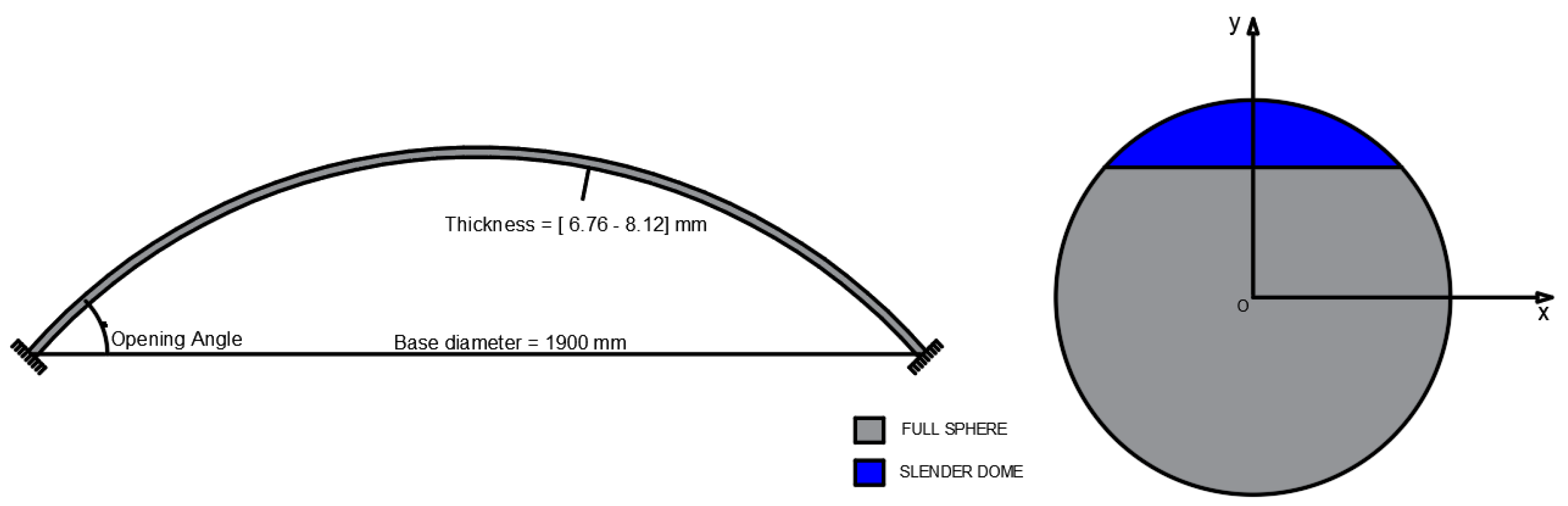
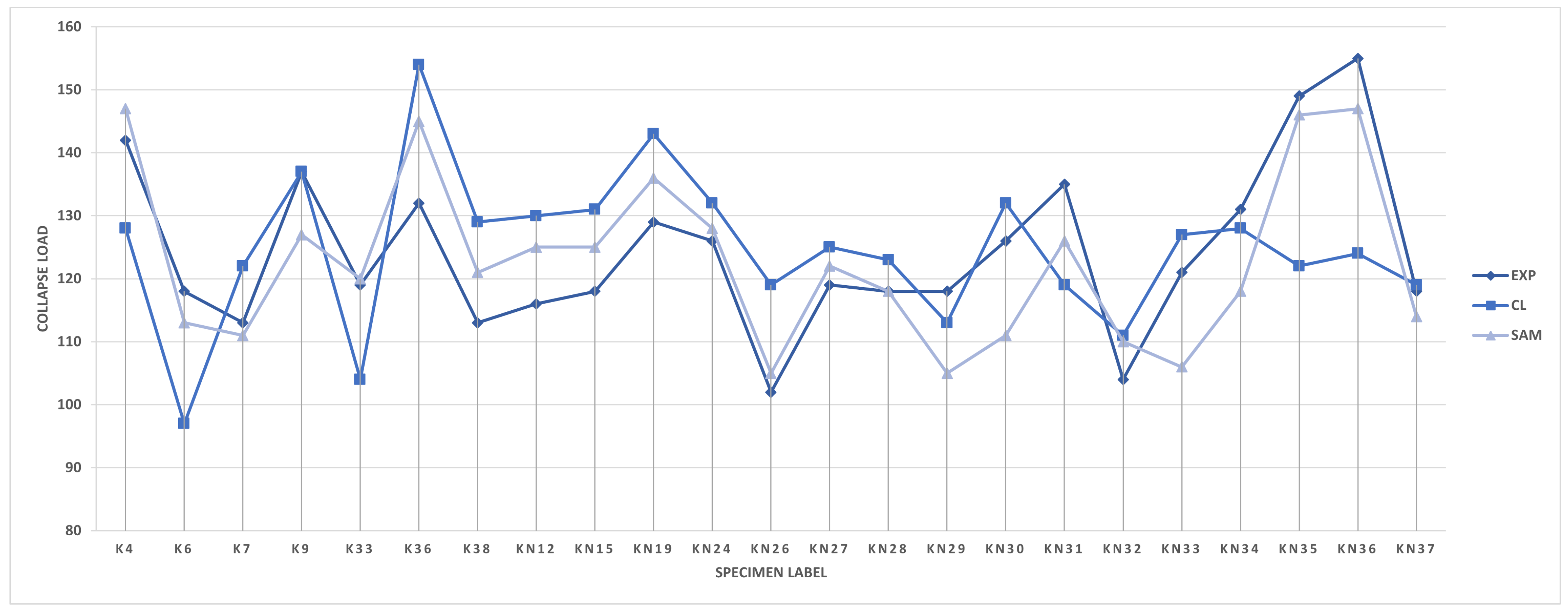
4. Case Study: Concrete Caps Collapse Load

To validate the method with respect to the experimental data, a numerical campaign was developed. The analysis concerned slender spherical domes of unreinforced concrete clamped at the base and loaded by uniform radial pressure. The geometry data of the domes are depicted in Figure 6; the base diameter was set to 1900 mm and the opening angle is equal to 45 degrees for all the specimens. The thickness varied from 6.76 to 8.12 mm.
The concrete caps were calculated to obtain the limit uniform radial pressure triggering the collapse. The load program consisted of monotonically increasing radial pressure through a scalar multiplier k superimposed to a fixed uniform self-weight. The calculation searches for the collapse value of k, say s c , for which the compatibility conditions hold. The routine calculating the semianalytical solution of the self-equilibrium equation was implemented in a Mathematica® (Wolfram, Champaign, IL, USA) environment. The structure’s geometry was obtained from [14], so that it could be compared with the experimental results. In particular, several different domes were calculated, considering the reported experimental data where slight differences in the shells’ radius and thickness, strength, and elastic properties were considered. The detailed dimensions of the specimens are reported in Table 1.

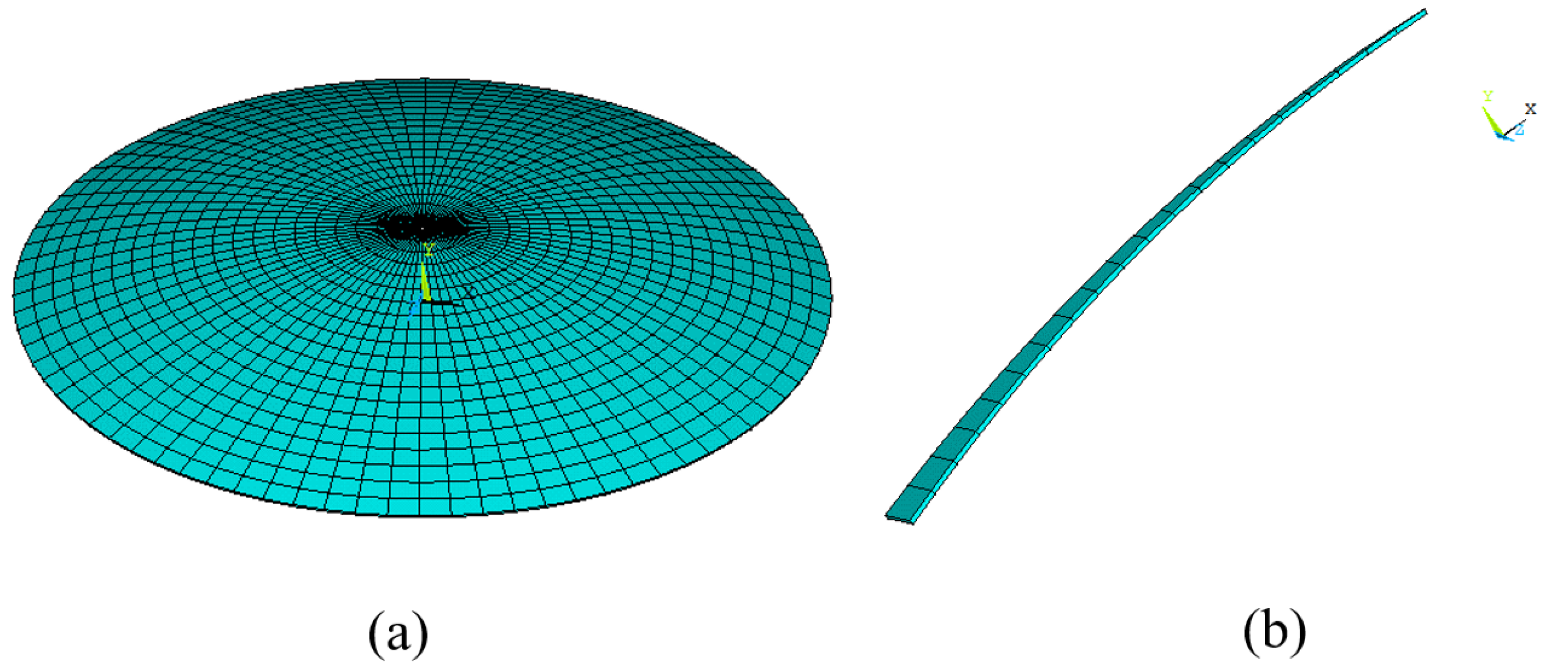
FEM Elastic Solution

The elastic response of the structures to the radial uniform pressure was calculated numerically using the finite-element Ansys© program. The elastic solution was collected in the matrix of elastic stresses containing parameters F * = { N i j e , M i j e , T i 1 e } calculated at discrete points on the meridian curve; see Figure 7. The FEM results were introduced into the semianalytical procedure described by Equation (14).
The caps were modeled using eight-node shell elements with 6 degrees of freedom for each node and quadratic shape functions. The axial forces and the bending moments acting on each shell element cross-section perpendicular to the parallels and meridians were collected. The numerical finite-element elastic solution and the semianalytical self-equilibrated solution were superimposed to obtain the statically admissible stress to introduce into the compatibility inequality constraints of the optimization program in Equation (14). The elastic solution was obtained at little computational cost, since only a linear elastic solution was calculated.

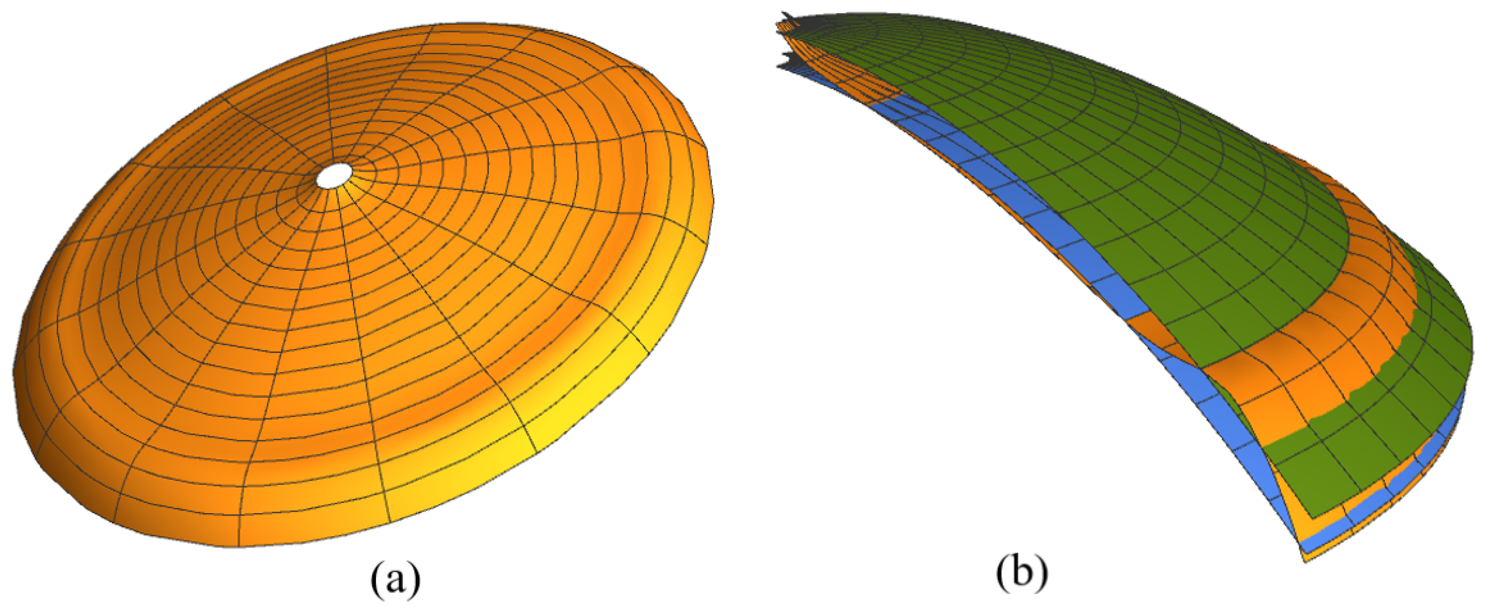
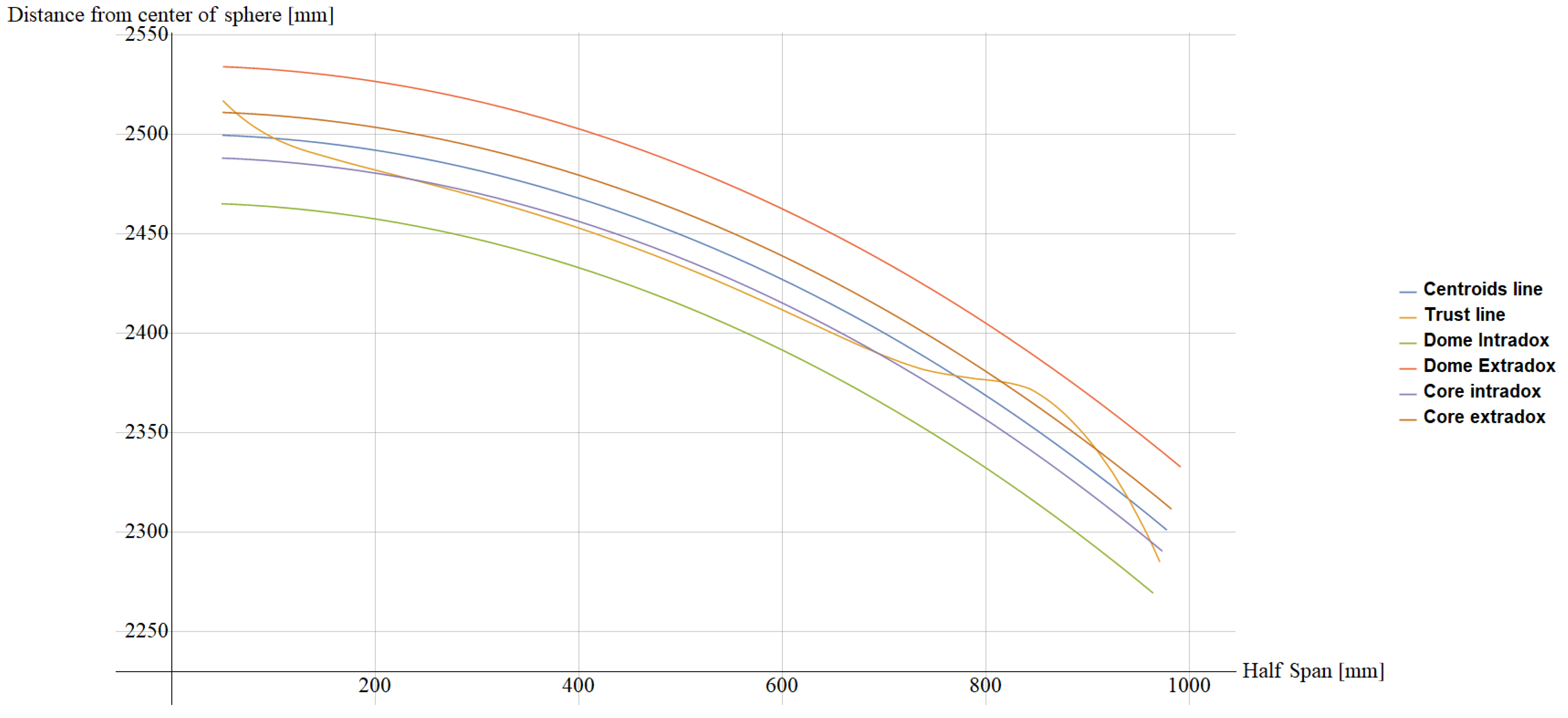
5. Results and Discussion

The obtained and literature results are summarized in Table 1. In particular, for each specimen besides the identifier, we indicate the thickness and radius of the dome, the compression stress limit, and Young’s modulus as reported in [14] and in [13,20]. The results of the present analysis are reported in comparison with the cited references. In particular, the table shows the collapse multiplier from the experiments of Vandepitte and Lagae [14] (EXP), the analytical value of the buckling load from [15] (BL), the numerical results obtained through the collapse line mechanism reported in [20] (CL), and the collapse load obtained from the present semianalytical method (SAM).
The SAM output consists of the load collapse multiplier and Melan’s residual stress representing the self-equilibrated stress that was summed to the elastic solution with respect to the compatibility constraints. Consequently, it was possible to calculate eccentricity e of the Melan compatible stress as follows:
e i j = M i j c N i j c
where M i j c and N i j c are the resulting stress from the optimization procedure.
Eccentricity is the distance along with the thickness of the cross-section of the center of trust C from the centroid of the section; hence, the line connecting the eccentricity of the sections is the trust line of the structure at the incoming collapse. Figure 8 shows the thrust line of the KN37 specimen meridian cross-section and the amplitude of the structure’s core and thickness. Such a line lies within the thickness of the structure. A three-dimensional representation of the trust locus is depicted in Figure 9 for the same sample, KN37.
Figure 10 shows a comparison of different models and experiments as a function of the specimen identifier. The calculation from CL and the experimental result by Ex were comparable, and the experimental results were lower than the calculated ones almost everywhere. Moreover, the theoretical buckling load, as reported by [20], deduced from [23], was always much greater than the experimental collapse load, which confirms that the collapse of the observed specimens occurred without meaningful geometric nonlinearity occurrence. The comparison shows that the proposed method gave accurate results with respect to the experimental and CL ones. Moreover, SAM results were almost everywhere between Ex and CL. The behavior of different procedures can be interpreted by considering that the proposed method applies the static approach; hence, it gives the lower bound of the actual collapse load. The analytical approach of [13] is based on the use of crack-line development and mechanism balance, so it consists of the application of a kinematic theorem. As a consequence, it furnishes an upper bound of the collapse load, as Figure 10 shows, where the CL results were higher than the experimental results almost everywhere. As was expected because of the theoretical statements, the proposed method produced results that were lower than those of CL almost everywhere. The semianalytical method, however, overestimated the experimental results of several specimens, since it is a discretized application of the lower bound theorem of the limit analysis; hence, it did not guarantee that the compatibility condition was enforced in the entire structure, but only at the sampling points. As a consequence, the calculated limit load had to decrease at the increase in the number of sampling points, i.e., the number of discrete colatitude angles where the inequalities in Equation (14) were enforced [16].

6. Conclusions

This work presented a comparison between the semianalytical method developed in [18] with experiments reported in [14] and numerical calculations in [13,20]. The SAM, whose formulation was developed for spherical domes of a general shape under a generic load pattern, was particularized to slender caps to compare the strategy with the experimental results and theoretical methods on the basis of fracture lines and the kinematic approach. The constitutive law and the corresponding limit domain of the structural material were derived considering the not-tensile-resistant material model of the unreinforced concrete, such as that used for the reference concrete caps in [13,14,20]. The collapse multiplier was determined by evaluating the existence of a statically admissible state of stress under loads of prescribed intensity. The statically admissible stress state consisted of the sum of the semianalytical solution of the balance equation of spherical domes and the simple linearly elastic solution under the prescribed load, obtained through a finite-element linear solution. The comparison between the experimental results and the simplest closed-form solution of domes under radial pressure shows that the method could accurately predict the collapse load. The method can be applied to spherical domes under axial–symmetrical loads; moreover, it can be applied to randomly variable loads to obtain the shakedown limit of the structures without any complications. The method requires the knowledge of a linearly elastic solution under the prescribed loads; this solution can be derived from a closed-form one if it exists or from any numerical solution obtained through well-established methods. However, the required elastic solution is obtained by only using linearly elastic methods and does not require any iterative ultraelastic calculation. When the collapse multiplier for a prescribed load path must be numerically calculated, one must apply an iterative strategy and nonlinear plasticity constitutive laws, with the latter consisting not only of a limit domain, but also of the flow rule that influences the calculation effort and the computational time [24]. Lastly, the proposed procedure also calculates the structure’s Melan residuals and the compatible stress distribution at the incoming collapse that can be used to calculate the upper bounds of the plastic dissipation at the collapse [19].
In [17,18], the procedure was applied to domes of revolution of different shapes and under several load conditions. In particular, parabolic and conical domes were analyzed with the geometry setup inspired by Santa Maria del Fiore and Saint Paul domes, respectively. The domes were loaded with uniform radial pressure, radial outward load, radial inward load, and vertical load on a generic parallel. The obtained outcomes were compared to FE-based commercial code ones. In the present work, the results were compared to experimental data, confirming the proposed procedure’s feasibility.
In conclusion, the results obtained in the present work were first compared with the analytical solution proposed by [20], and then with the numerical experiment proposed by [14]. The proposed method demonstrates its ability to obtain the load multiplier with no assumptions about the collapse mechanism. Independence from collapse-mechanism knowledge is another relevant advantage of such a static approach that allows for formulating the limit equilibrium of the structures with no a priori intuition of kinematics and collapse shape.
The proposed strategy will be applied to a broader set of geometry and load conditions, paving the way to a standard procedure for collapse-load multiplier evaluation.

Author Contributions

Conceptualization, R.Z. and V.M.; methodology, V.M.; software, V.M. and R.Z.; validation, R.Z., V.M. and L.E.; formal analysis, V.M.; investigation, R.Z., S.P., L.E., E.T. and V.M.; resources, V.M.; data curation, R.Z., S.P. and L.E.; writing—original draft preparation, R.Z.; writing—review and editing, R.Z. and V.M.; visualization, R.Z., V.M. and L.E.; supervision, V.M.; project administration, V.M.; funding acquisition, V.M. All authors have read and agreed to the published version of the manuscript.

Funding

This research was funded by the Università degli Studi della Campania ‘L Vanvitelli’, grant Programma VALERE: ‘VAnviteLli pEr la RicErca’, DDG n. 516-24/05/2018.

Institutional Review Board Statement

Not applicable.

Informed Consent Statement

Not applicable.

Data Availability Statement

Not applicable.

Conflicts of Interest

The authors declare no conflict of interest.

References

  1. Milani, E.; Milani, G.; Tralli, A. Limit analysis of masonry vaults by means of curved shell finite elements and homogenization. Int. J. Solids Struct. 2008, 45, 5258–5288. [Google Scholar] [CrossRef]
  2. Block, P.; Ciblac, T.; Ochsendorf, J. Real-time limit analysis of vaulted masonry buildings. Comput. Struct. 2006, 84, 1841–1852. [Google Scholar] [CrossRef]
  3. Block, P.; Ochsendorf, J. Thrust network analysis: A new methodology for three-dimensional equilibrium. J. Int. Assoc. Shell Spat. Struct. 2007, 48, 167–173. [Google Scholar]
  4. Block, P.; Lachauer, L. Three-dimensional (3D) equilibrium analysis of gothic masonry vaults. Int. J. Archit. Herit. 2014, 8, 826301. [Google Scholar] [CrossRef]
  5. Avelino, R.M.; Iannuzzo, A.; Mele, T.V.; Block, P. Assessing the safety of vaulted masonry structures using thrust network analysis. Comput. Struct. 2021, 257, 106647. [Google Scholar] [CrossRef]
  6. Save, M. Limit analysis and design of containment vessels. Nucl. Eng. Des. 1984, 79, 343–361. [Google Scholar] [CrossRef]
  7. Moncarz, P.D.; Griffith, M.; Noakowski, P. Collapse of a Reinforced Concrete Dome in a Wastewater Treatment Plant Digester Tank. J. Perform. Constr. Facil. 2007, 21, 4–12. [Google Scholar] [CrossRef]
  8. Teng, J.G.; Rotter, J.M. Geometrically and materially nonlinear analysis of reinforced concrete shells of revolution. Comput. Struct. 1992, 42, 327–340. [Google Scholar] [CrossRef]
  9. Zingoni, A.; Enoma, N. Strength and stability of spherical-conical shell assemblies under external hydrostatic pressure. Thin-Walled Struct. 2020, 146, 106472. [Google Scholar] [CrossRef]
  10. Zingoni, A. Stress and buckling resistance of dual-purpose concrete shells. Thin-Walled Struct. 2022, 170, 108596. [Google Scholar] [CrossRef]
  11. Stockdale, G.; Milani, G. Diagram based assessment strategy for first-order analysis of masonry arches. J. Build. Eng. 2019, 22, 122–129. [Google Scholar] [CrossRef]
  12. Mercuri, M.; Pathirage, M.; Gregori, A.; Cusatis, G. Masonry vaulted structures under spreading supports: Analyses of fracturing behavior and size effect. J. Build. Eng. 2022, 45, 103396. [Google Scholar] [CrossRef]
  13. Chang, Z.T.; Bradford, M.A.; Gilbert, R.I. Short-term behaviour of shallow thin-walled concrete dome under uniform external pressure. Thin-Walled Struct. 2011, 49, 112–120. [Google Scholar] [CrossRef]
  14. Vandepitte, D.; Lagae, G. Buckling of Spherical Domes Made of Microconcrete and Creep Buckling of Such Domes Under Long-term Loading. In Proceedings of the Inelastic Behaviour of Plates and Shells, Rio de Janeiro, Brazil, 5–9 August 1985; Bevilacqua, L., Feijóo, R., Valid, R., Eds.; Springer: Berlin/Heidelberg, Germany, 1986; pp. 291–311. [Google Scholar]
  15. Zoelly, R. Uber ein Knickungs Problem an der Kugelschale. Ph.D. Thesis, ETH Druck von Zurker & Furrer, Zürich, Switzerland, 1915. [Google Scholar]
  16. Palladino, S.; Esposito, L.; Ferla, P.; Totaro, E.; Zona, R.; Minutolo, V. Experimental and numerical evaluation of residual displacement and ductility in ratcheting and shakedown of an aluminum beam. Appl. Sci. 2020, 10, 3610. [Google Scholar] [CrossRef]
  17. Zona, R.; Esposito, L.; Ferla, P.; Palladino, S.; Totaro, E.; Minutolo, V. Lower bound limit analysis of parabolic domes based on spherical analytical solution. Int. J. Adv. Res. Eng. Technol. 2020, 11, 59–79. [Google Scholar] [CrossRef]
  18. Zona, R.; Ferla, P.; Minutolo, V. Limit analysis of conical and parabolic domes based on semi-analytical solution. J. Build. Eng. 2021, 44, 103271. [Google Scholar] [CrossRef]
  19. Lubliner, J. Plasticity Theory; Macmillan Pub Co.: New York, NY, USA, 1990. [Google Scholar]
  20. Chang, Z.T.; Bradford, M.A.; Gilbert, R.I. Limit analysis of local failure in shallow spherical concrete caps subjected to uniform radial pressure. Thin-Walled Struct. 2010, 48, 373–378. [Google Scholar] [CrossRef]
  21. Timoshenko, S.P. Theory of Plates and Shells, 1st ed.; McGraw-Hill: New York, NY, USA, 1964; Volume 1. [Google Scholar]
  22. Heyman, J. The stone skeleton. Int. J. Solids Struct. 1966, 2, 249–279. [Google Scholar] [CrossRef]
  23. O’Dwyer, D. Funicular analysis of masonry vaults. Comput. Struct. 1999, 73, 187–197. [Google Scholar] [CrossRef]
  24. Clementi, F.; Gazzani, V.; Poiani, M.; Lenci, S. Assessment of seismic behaviour of heritage masonry buildings using numerical modelling. J. Build. Eng. 2016, 8, 29–47. [Google Scholar] [CrossRef]
Figure 1. Stress resultants on the dome infinitesimal element.
Applsci 12 09155 g001
Figure 2. Center of thrust at a cross-section.
Applsci 12 09155 g002
Figure 3. (a) Geometric parameters; (b) infinitesimal element of the dome.
Applsci 12 09155 g003
Figure 4. Cap limit domain per unit width cross-section; blue and orange curves correspond to +/− sign in Equation (12).
Applsci 12 09155 g004
Figure 5. Linearization of the limit domain; blue, orange lines correspond to the sign of Equation (13).
Applsci 12 09155 g005
Figure 6. Geometry of the slender spherical domes. The origin of the reference frame is the center of the sphere, and its radius was in the range of 2428–2560 mm.
Applsci 12 09155 g006
Figure 7. Cap discretization: (a) Whole model; (b) single meridian element selection.
Applsci 12 09155 g007
Figure 8. Thrust line along with meridian and thickness.
Applsci 12 09155 g008
Figure 9. (a) Three-dimensional representation of the locus of the centers of axial forces: thrust surface; (b) axonometric section with the indication of the core thickness.
Applsci 12 09155 g009
Figure 10. Collapse load from EXP, CL, and present SAM procedure.
Applsci 12 09155 g010
Table 1. Specimen data and result comparison.
SpecimenThicknessRadiusStrengthYoung’s Modulus(Ex)BL(CL)SAM(Ex)/SAM
K47.1224316030,3561423051281471.035
K67.0724384625,667118254971130.958
K76.9124285922,7991132171221110.982
K96.9824506629,0131372761371270.927
K336.9124695133,6521193101041201.008
K366.924797631,5271322861541451.098
K386.8625246529,2691132551291211.071
KN127.0725386426,1261162401301251.078
KN156.9425546626,5371182301311251.059
KN196.9925377134,2301293041431361.054
KN247.125606532,1761262961321281.016
KN267.0625465926,7661022421191051.029
KN277.0925576230,5231192761251221.025
KN287.0125406130,0331182691231181
KN296.7625355831,4491182631131050.89
KN306.9825155832,9581262981321110.881
KN317.0425006533,8251353061191260.933
KN326.9325005826,9041042361111101.058
KN337.0225005526,8881212431271060.876
KN346.9425006228,9621312541281180.901
KN356.8325006334,2081492921221460.98
KN366.9825006134,7601553101241470.948
KN376.8925006133,3261182901191140.966
Publisher’s Note: MDPI stays neutral with regard to jurisdictional claims in published maps and institutional affiliations.

