
A Compact Broadband Planar Inverted-F Antenna with Dual-Resonant Modes

Abstract
:1. Introduction
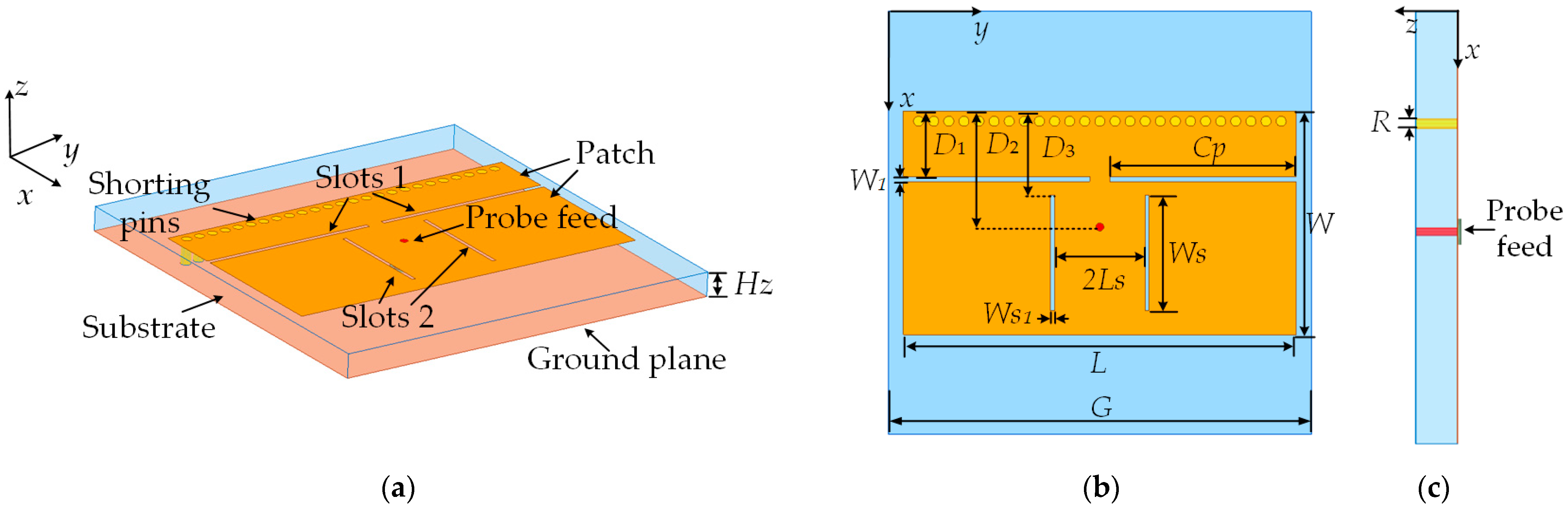
2. Geometry
3. Principle and Analysis
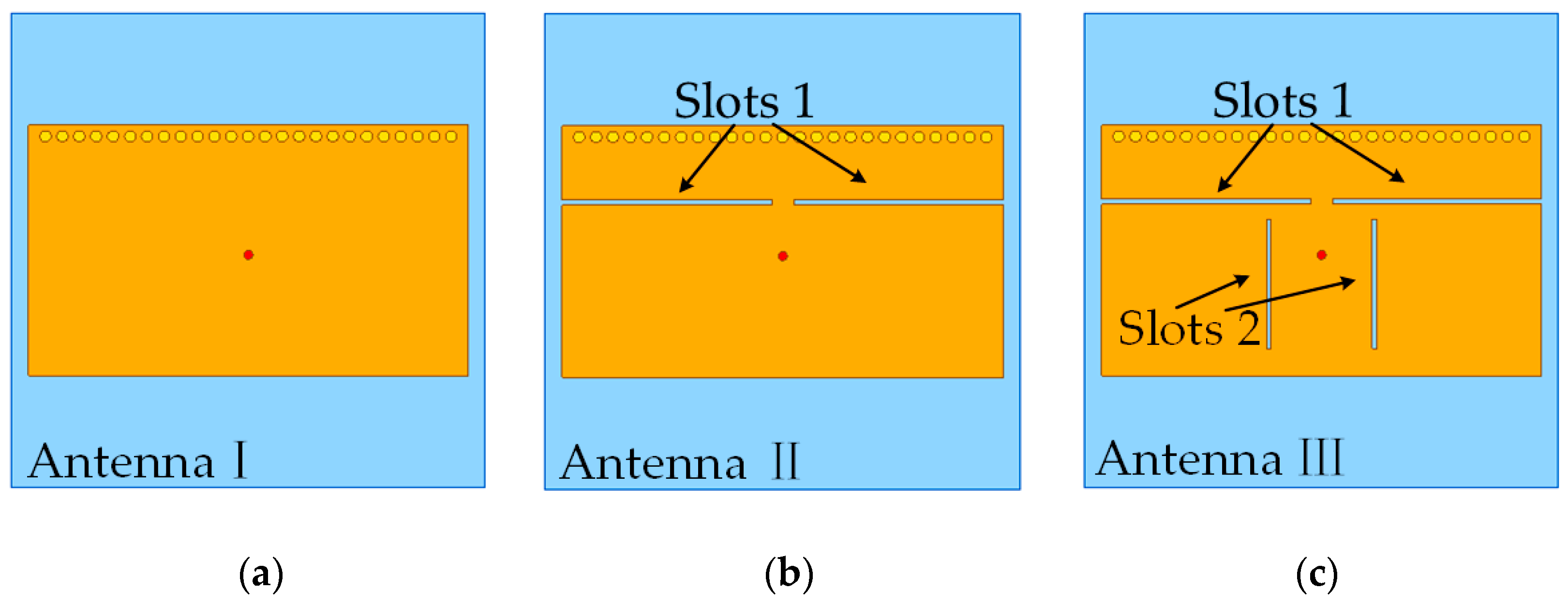
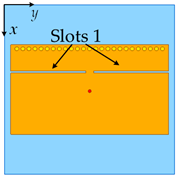
3.1. Loading of Slots 1
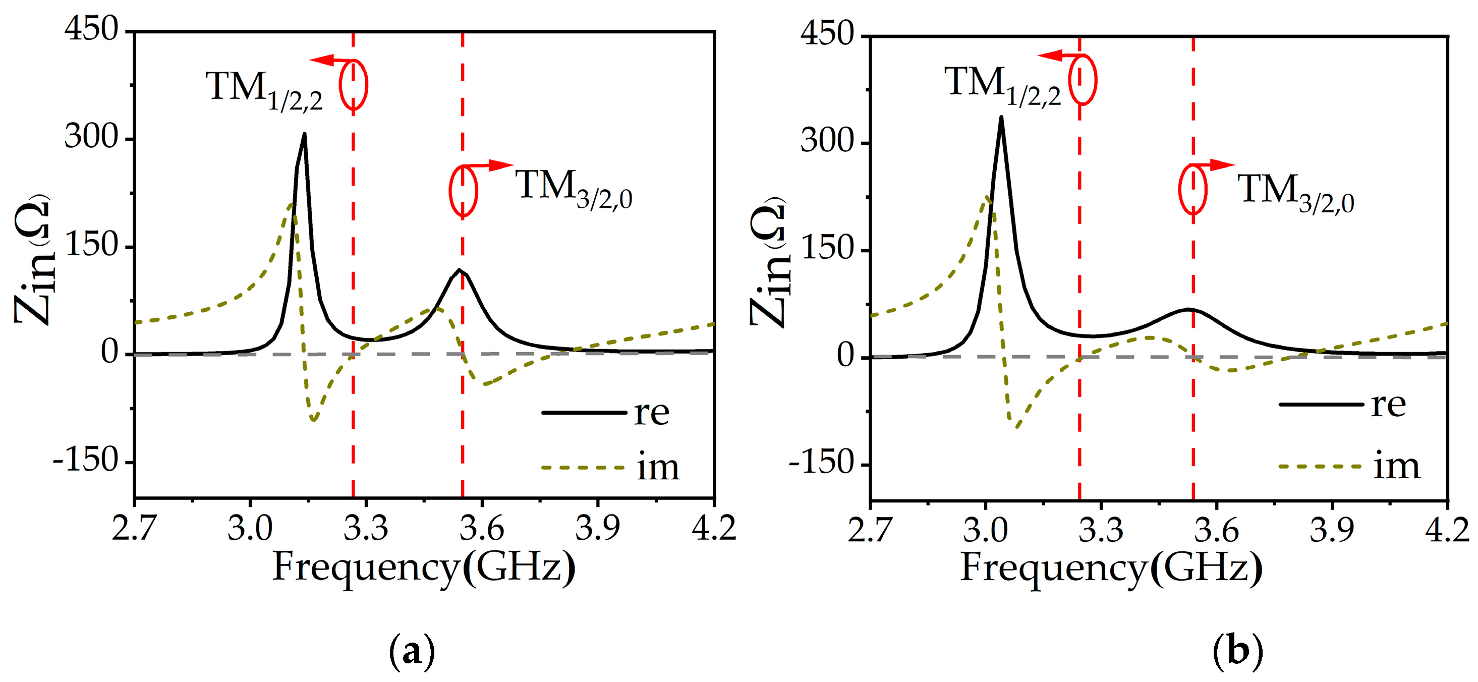
3.1.1. Closing the Resonant Frequencies of the Two Modes
3.1.2. Improving the Radiation Pattern
3.2. Loading of Slots 2
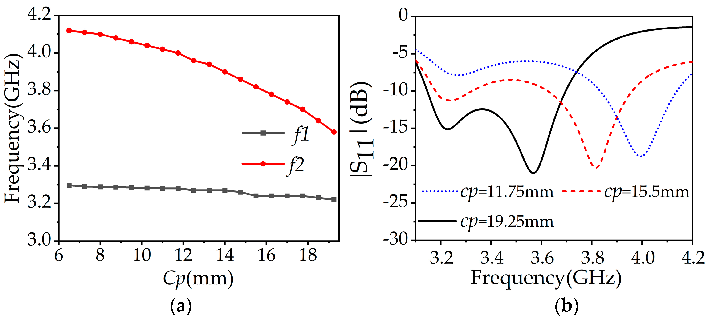
3.3. Parametric Studies
3.4. Design Guideline
- 1.
- Determining the initial values of the antenna structure. The antenna is supposed to operate under the resonances of TM1/2,2 and TM3/2,0 modes. For a conventional PIFA (L/W ≈ 2), the initial size can be estimated by referring to [27].
- 2.
- 3.
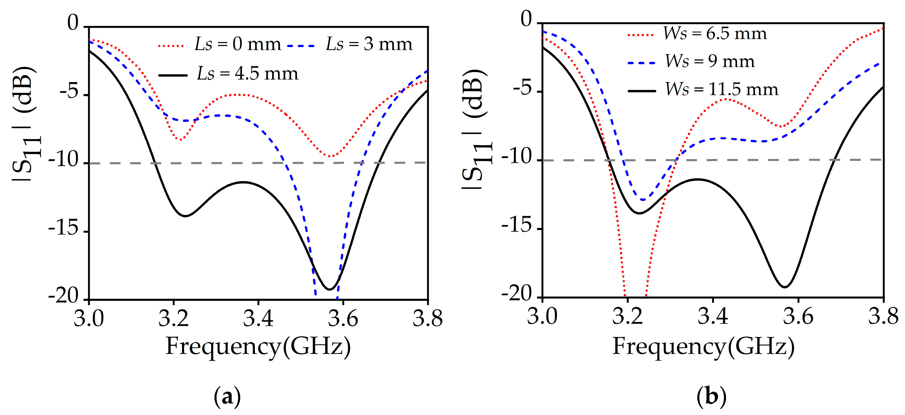
- Loading Slots 2 to improve impedance matching. Adjusting the length (Ws) and position (Ls) of Slots 2 can lead to better impedance matching, as shown in Figure 6a,b.
- 4.
- Optimizingthe final structure. The parameters of slots (cp, Ws, Ls, D1, and D3) and feed structure (D2) can be further adjusted to obtain an optimized performance.
4. Experiment Result
5. Conclusions
Author Contributions
Funding
Institutional Review Board Statement
Informed Consent Statement
Conflicts of Interest
References
- Xu, J.; Hong, W.; Jiang, Z.H.; Zhang, H.; Wu, K. Low-Profile Wideband Vertically Folded Slotted Circular Patch Array for Ka -Band Applications. IEEE Trans. Antennas Propag. 2020, 68, 6844–6849. [Google Scholar] [CrossRef]
- Varum, T.; Caiado, J.; Matos, J. Compact Ultra-Wideband Series-Feed Microstrip Antenna Arrays for IoT Communications. Appl. Sci. 2021, 14, 6267. [Google Scholar] [CrossRef]
- Chang, L.; Wang, H. Dual-Band four-antenna module covering N78/N79 based on PIFA for 5G terminals. IEEE Antennas Wirel. Propag. Lett. 2022, 21, 168–172. [Google Scholar] [CrossRef]
- Fakih, M.A.; Diallo, A.; Le Thuc, P.; Staraj, R.; Mourad, O.; Rachid, E.A. Optimization of efficient dual band PIFA system for MIMO half-duplex 4G/LTE and full-duplex 5G communications. IEEE Access 2019, 7, 128881–128895. [Google Scholar] [CrossRef]
- Shao, Z.; Zhang, Y.P. Miniaturization of differentially-driven microstrip planar inverted F antenna. IEEE Trans. Antennas Propag. 2019, 67, 1280–1283. [Google Scholar] [CrossRef]
- Ramírez, G.A. Reconfigurable dual-polarized beam-steering broadband antenna using a crossed-strips geometry. IEEE Antennas Wireless Propag. Lett. 2021, 20, 1379–1383. [Google Scholar] [CrossRef]
- Tian, M.; Yan, N.; Luo, Y.; Ma, K. A low-cost high-gain filtering patch antenna using SISL technology for 5G application. IEEE Antennas Wirel. Propag. Lett. 2021, 20, 2270–2274. [Google Scholar] [CrossRef]
- Gao, M.; Zhao, X. Design of Tri-Band Patch Antenna with Enhanced Bandwidth and Diversity Pattern for Indoor Wireless Communication. Appl. Sci. 2022, 12, 7445. [Google Scholar] [CrossRef]
- Li, T.; Chen, Z.N. A dual-band metasurface antenna using characteristic mode analysis. IEEE Trans. Antennas Propag. 2018, 66, 5620–5624. [Google Scholar] [CrossRef]
- Liu, W.E.I.; Chen, Z.N.; Qing, X. Miniature wideband non-uniform metasurface antenna using equivalent circuit model. IEEE Trans. Antennas Propag. 2020, 68, 5652–5657. [Google Scholar] [CrossRef]
- Liu, S.; Yang, D.; Chen, Y.; Zhang, X.; Xiang, Y. High isolation and low cross-polarization of low-profile dual-polarized antennas via metasurface mode optimization. IEEE Trans. Antennas Propag. 2021, 69, 2999–3004. [Google Scholar] [CrossRef]
- Ntawangaheza, J.d.D.; Sun, L.; Li, Y.; Biao, D.; Xie, Z.; Rushingabigwi, G. A single-layer planar low-profile wideband microstrip line-fed metasurface antenna. IEEE Antennas Wirel. Propag. Lett. 2021, 20, 1641–1645. [Google Scholar] [CrossRef]
- Liu, W.E.I.; Chen, Z.N.; Qing, X. Broadband low-profile L-probe fed metasurface antenna with TM leaky wave and TE surface wave resonances. IEEE Trans. Antennas Propag. 2020, 68, 1348–1355. [Google Scholar] [CrossRef]
- Bae, H.H.; Jang, T.H.; Kim, H.Y.; Park, C.S. Broadband 120 GHz L-probe differential feed dual-polarized patch antenna with soft surface. IEEE Trans. Antennas Propag. 2021, 69, 6185–6195. [Google Scholar] [CrossRef]
- Luo, K.; Wang, Q.; Meng, J.; Ge, S.; Liu, H. A narrow-strip broadband microstrip antenna with L-probe fed. IEEE Access 2020, 8, 60484–60490. [Google Scholar] [CrossRef]
- Zhang, X.; Tan, T.-Y.; Wu, Q.-S.; Zhu, L.; Zhong, S.; Yuan, T. Pin-loaded patch antenna fed with a dual-mode SIW resonator for bandwidth enhancement and stable high gain. IEEE Antennas Wirel. Propag. Lett. 2021, 20, 279–283. [Google Scholar] [CrossRef]
- Liu, Q.; Zhu, L.; Wang, J.; Wu, W. A wideband patch and SIW cavity hybrid antenna with filtering response. IEEE Antennas Wirel. Propag. Lett. 2020, 19, 836–840. [Google Scholar] [CrossRef]
- Liu, N.-W.; Zhu, L.; Choi, W.-W.; Zhang, X. A low-profile differential-fed patch antenna with bandwidth enhancement and sidelobe reduction under operation of TM10 and TM12 modes. IEEE Trans. Antennas Propag. 2018, 66, 4854–4859. [Google Scholar] [CrossRef]
- Wang, J.; Li, Y.; Wang, J. A low-profile dual-mode slot-patch antenna for 5G millimeter-wave applications. IEEE Antennas Wirel. Propag. Lett. 2022, 21, 625–629. [Google Scholar] [CrossRef]
- Gan, Z.; Tu, Z.-H. Dual-mode conjoint patch-pair for 5G wideband patch antenna array application. IEEE Antennas Wirel. Propag. Lett. 2021, 20, 244–248. [Google Scholar] [CrossRef]
- Hu, W.; Li, C.; Liu, X.; Wen, L.; Feng, T.; Jiang, W.; Gao, S. Wideband circularly polarized microstrip patch antenna with multimode resonance. IEEE Antennas Wirel. Propag. Lett. 2021, 20, 533–537. [Google Scholar] [CrossRef]
- Bahrami, S.; Moloudian, G.; Miri-Rostami, S.R.; Björninen, T. Compact microstrip antennas with enhanced bandwidth for the implanted and external subsystems of a wireless retinal prosthesi. IEEE Trans. Antennas Propag. 2021, 69, 2969–2974. [Google Scholar] [CrossRef]
- Zhang, X.; Hong, K.-D.; Zhu, L.; Bi, X.-K.; Yuan, T. Wideband differentially fed patch antennas under dual high-order modes for stable high gain. IEEE Trans. Antennas Propag. 2021, 69, 508–513. [Google Scholar] [CrossRef]
- Liu, X.; Hu, W.; Gao, S.S.; Wen, L.; Luo, Q.; Xu, R.; Liu, Y. A wideband triple-mode differentially fed microstrip patch antenna. IEEE Antennas Wirel. Propag. Lett. 2021, 20, 1160–1164. [Google Scholar] [CrossRef]
- Gao, G.; Yang, C.; Hu, B.; Zhang, R.; Wang, S. A wide-bandwidth wearable all-textile PIFA with dual resonance modes for 5 GHz WLAN applications. IEEE Trans. Antennas Propag. 2019, 67, 4206–4211. [Google Scholar] [CrossRef]
- Liu, N.; Zhu, L.; Choi, W.; Zhang, X. Wideband shorted patch antenna under radiation of dual-resonant modes. IEEE Trans. Antennas Propag. 2017, 65, 2789–2796. [Google Scholar] [CrossRef]
- Liu, N.; Zhu, L.; Choi, W. A low-profile wide-bandwidth planar inverted-F antenna under dual resonances: Principle and design approach. IEEE Trans. Antennas Propag. 2017, 65, 5019–5025. [Google Scholar] [CrossRef]
- Radavaram, S.; Naik, S.; Pour, M. Stably polarized wideband circular microstrip antenna excited in TM12 mode. IEEE Trans. Antennas Propag. 2021, 69, 2370–2375. [Google Scholar] [CrossRef]
- ANSYS. High Frequency Structure Simulator (HFSS 18.9); ANSYS: Canonsburg, PA, USA, 2018. [Google Scholar]
- Liu, N.-W.; Zhu, L.; Liu, Z.-X.; Zhang, Z.-Y.; Fu, G.; Liu, Y. Cross-polarization reduction of a shorted patch antenna with broadside radiation using a pair of open-ended stubs. IEEE Trans. Antennas Propag. 2020, 68, 13–20. [Google Scholar] [CrossRef]
- Zhou, C.; Guo, L.; Li, Q.; Li, H. A differentially fed hybrid dipole, slot, and patch antenna with unidirectional radiation patterns. IEEE Trans. Antennas Propag. 2020, 68, 2603–2611. [Google Scholar] [CrossRef]
- Wu, Y.-S.; Chu, Q.-X.; Huang, H.-Y. Electromagnetic transparent antenna with slot-loaded patch dipoles in dual-band array. IEEE Trans. Antennas Propag. 2022; accepted. [Google Scholar] [CrossRef]
- Jian, R.; Chen, Y.; Chen, T. A low-profile wideband PIFA based on radiation of multiresonant modes. IEEE Antennas Wirel. Propag. Lett. 2020, 19, 685–689. [Google Scholar] [CrossRef]
- Wen, J.; Xie, D.; Zhu, L. Bandwidth-Enhanced high-gain microstrip patch antenna under TM30 and TM50 dual-mode resonances. IEEE Antennas Wirel. Propag. Lett. 2019, 18, 1976–1980. [Google Scholar] [CrossRef]


| Parameters | Values (mm) | Parameters | Values (mm) |
|---|---|---|---|
| G | 42 | Ws1 | 0.4 |
| Hz | 2.54 | D1 | 6.5 |
| L | 39 | D2 | 11.5 |
| Ls | 4.5 | D3 | 7.25 |
| W | 22.2 | Cp | 19.25 |
| W1 | 0.5 | R | 0.5 |
| Ws | 11.5 |
| Antenna I | Antenna II |
|---|---|
| Structure | |
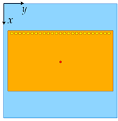 |  |
Current distribution of the TM1/2,2 mode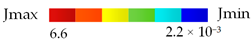 | |
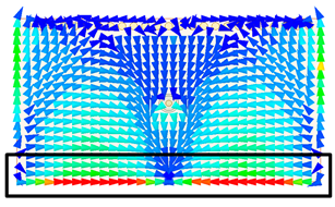 Edge for main radiation |  Slots for main radiation |
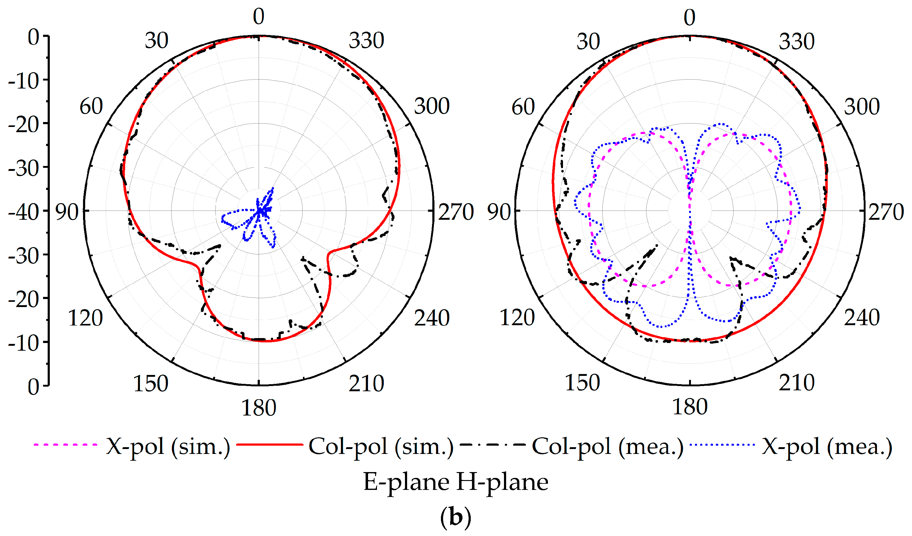
| Radiation patterns of the TM1/2,2 mode | |
Peak gain: 3.03dBi @ 270°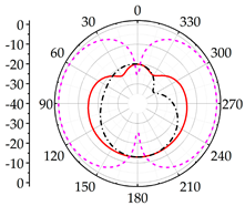 | 7.2dBi @ 0°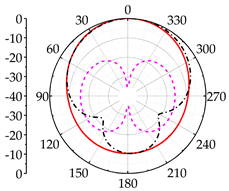 |
 | |
Current distribution of the TM3/2,0 mode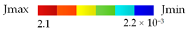 | |
 |  |
| Radiation patterns of the TM3/2,0 mode | |
Peak gain: 7.46dBi @ 330° | 6.36dBi @ 0°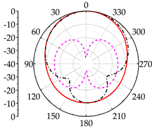 |
 | |
| Refs. | f0 (GHz) | BW (%) | Peak Gain (dBi) | Efficiency (%) | Radiation Pattern | Resonant Modes | Size (λ03) |
|---|---|---|---|---|---|---|---|
| [17] | 3.50 | 9.14 | 7.30 | 80 | Good | TM1,1, TM2,1 | 0.74 × 0.74 × 0.04 |
| [18] | 1.90 | 10.0 | 11 | 85 | Good | TM1,0, TM1,2 | 1.71 × 0.51 × 0.04 |
| [25] | 5.5 | 18.0 | 5.9 | 74.1 | Asymmetry 35°-tilt | TM0,1/2, TM0,3/2 | 0.55 × 0.37 × 0.04 |
| [26] | 4.10 | 11.8 | 3.5 | 85 | Asymmetry 30°-tilt | TM0,1/2, TM0,3/2 | 0.41 × 0.34 × 0.04 |
| [27] | 2.49 | 15.3 | 5 | - | High cross-pol (over −5dB) | TM0,1/2, TM2,1/2 | 1.00 × 0.27 × 0.04 |
| [34] | 5.5 | 6.1 | 10.7 | - | Good | TM3,0, TM5,0 | 1.05 × 0.86 × 0.015 |
| This work | 3.45 | 14.5 | 6.23 | 83 | Good | TM1/2,2, TM3/2,0 | 0.45 × 0.26 × 0.03 |
Publisher’s Note: MDPI stays neutral with regard to jurisdictional claims in published maps and institutional affiliations. |
© 2022 by the authors. Licensee MDPI, Basel, Switzerland. This article is an open access article distributed under the terms and conditions of the Creative Commons Attribution (CC BY) license (https://creativecommons.org/licenses/by/4.0/).
Share and Cite
Qi, Z.; Ding, X.; Yang, W.; Chen, J. A Compact Broadband Planar Inverted-F Antenna with Dual-Resonant Modes. Appl. Sci. 2022, 12, 8915. https://doi.org/10.3390/app12178915
Qi Z, Ding X, Yang W, Chen J. A Compact Broadband Planar Inverted-F Antenna with Dual-Resonant Modes. Applied Sciences. 2022; 12(17):8915. https://doi.org/10.3390/app12178915
Chicago/Turabian StyleQi, Zhengya, Xinhao Ding, Wenwen Yang, and Jianxin Chen. 2022. "A Compact Broadband Planar Inverted-F Antenna with Dual-Resonant Modes" Applied Sciences 12, no. 17: 8915. https://doi.org/10.3390/app12178915
APA StyleQi, Z., Ding, X., Yang, W., & Chen, J. (2022). A Compact Broadband Planar Inverted-F Antenna with Dual-Resonant Modes. Applied Sciences, 12(17), 8915. https://doi.org/10.3390/app12178915