


Experimental Study and Engineering Application of the Spatial Reticulated Grid Bolt-Shotcrete Support Structure for Excavation Tunnels

Abstract
:1. Introduction
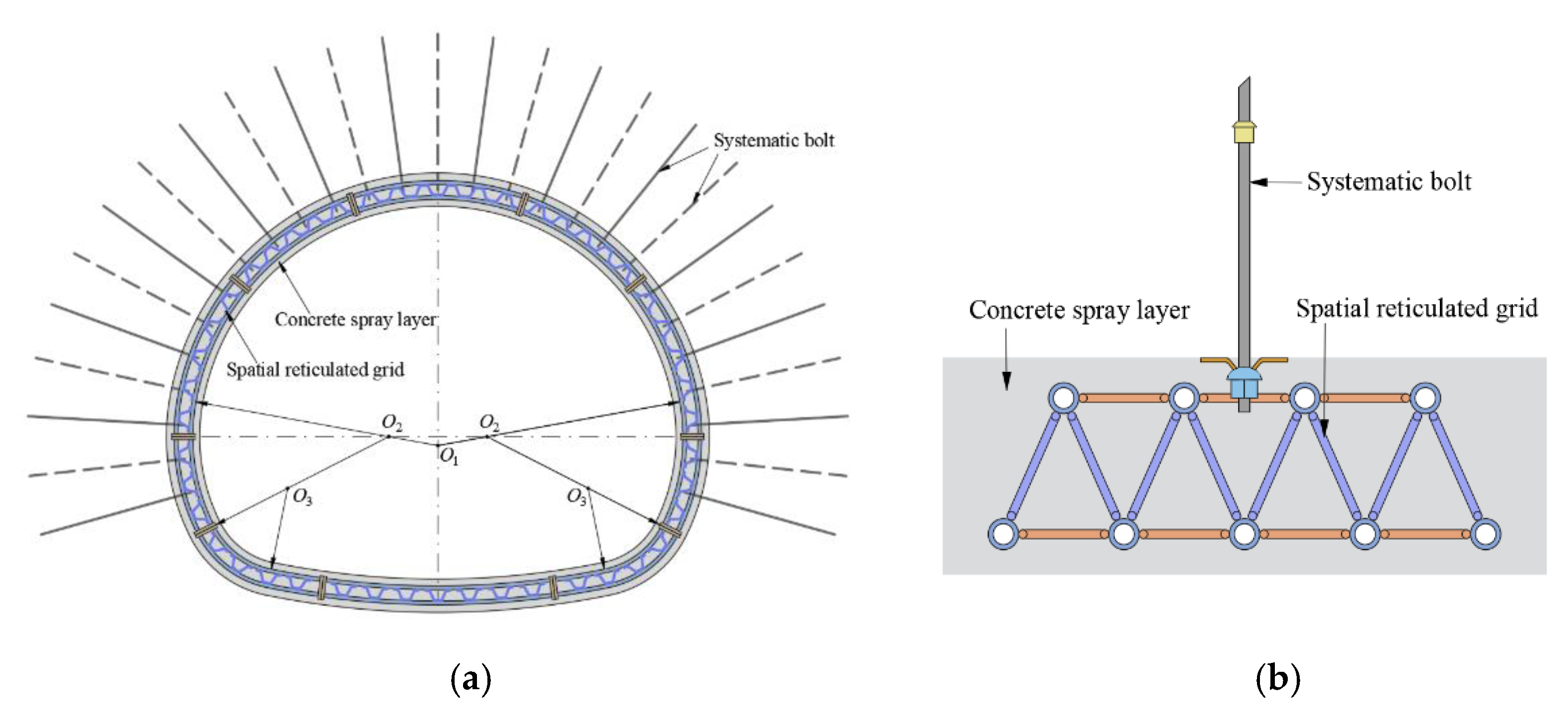
2. The Principle of the SRGB Support Structure
3. Indoor Tests of the Spatial Reticulated Grid Concrete Components
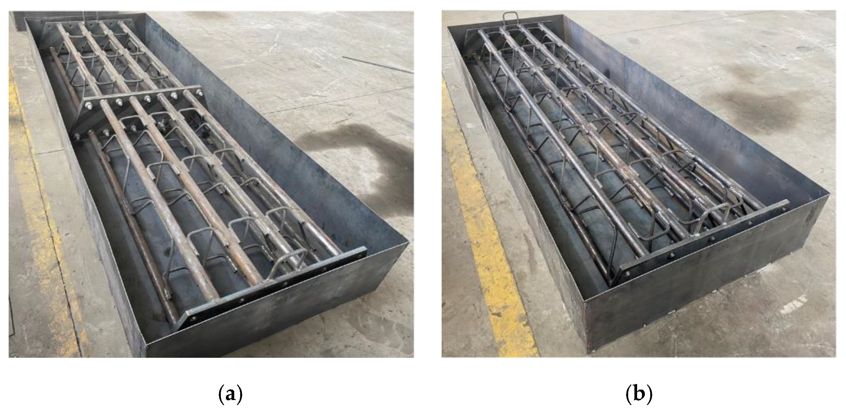
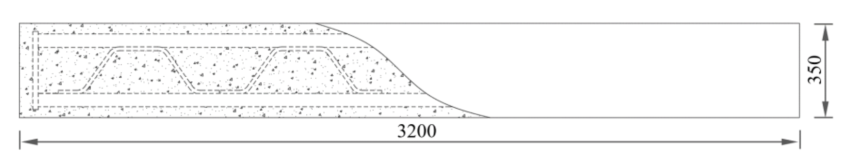
3.1. Component Design and Production
3.1.1. Component Design
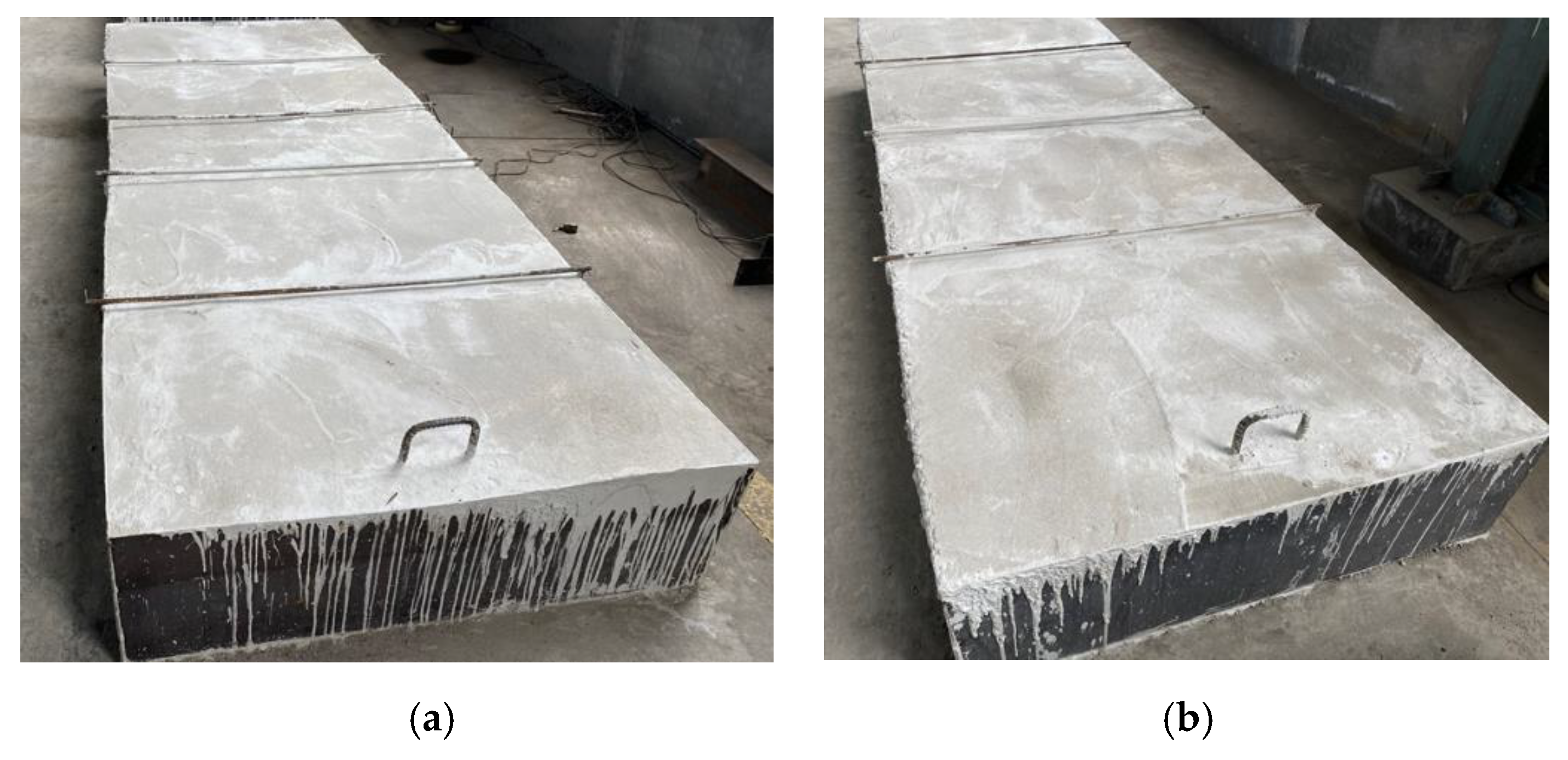
3.1.2. Component Production
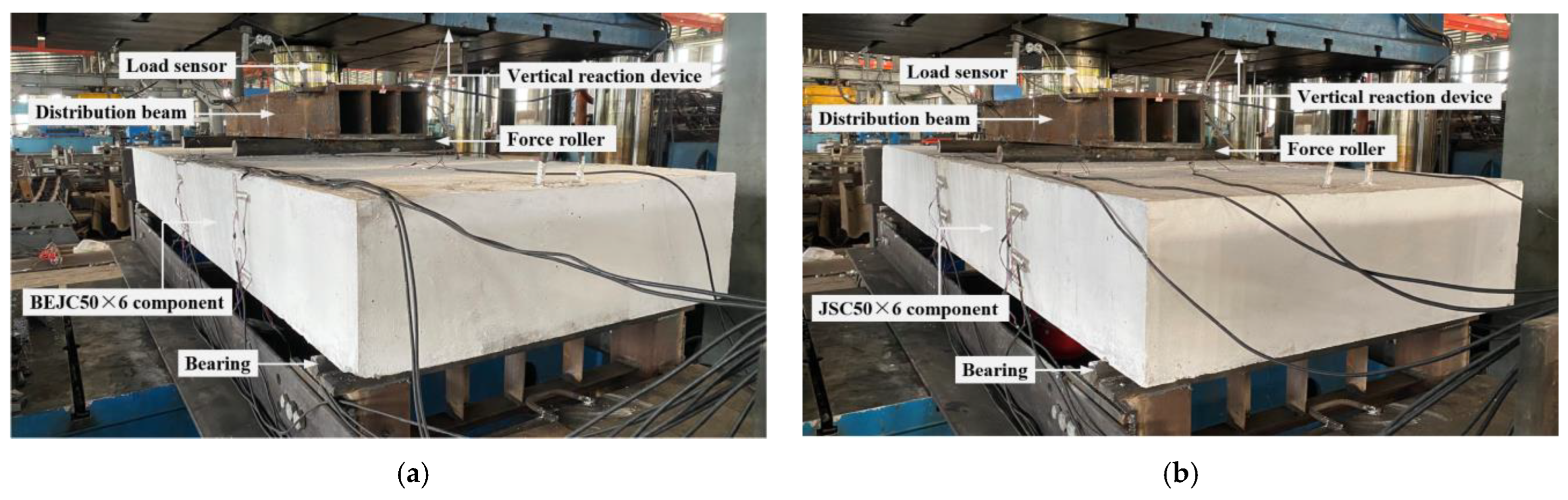
3.2. Test Loading and Measurement
3.3. Test Results and Analysis
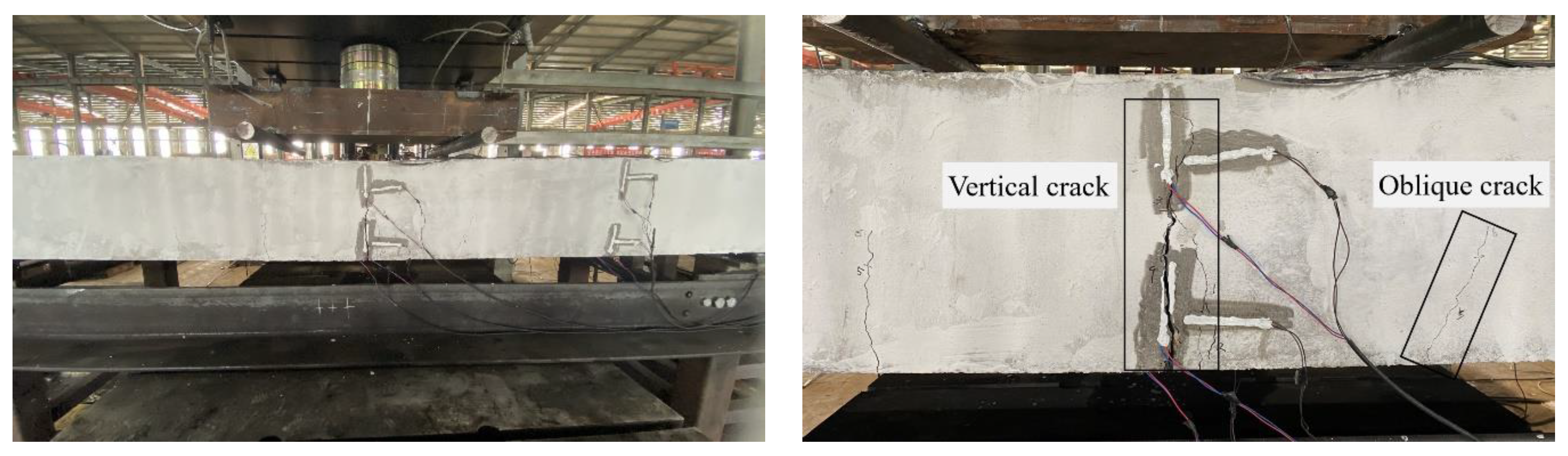
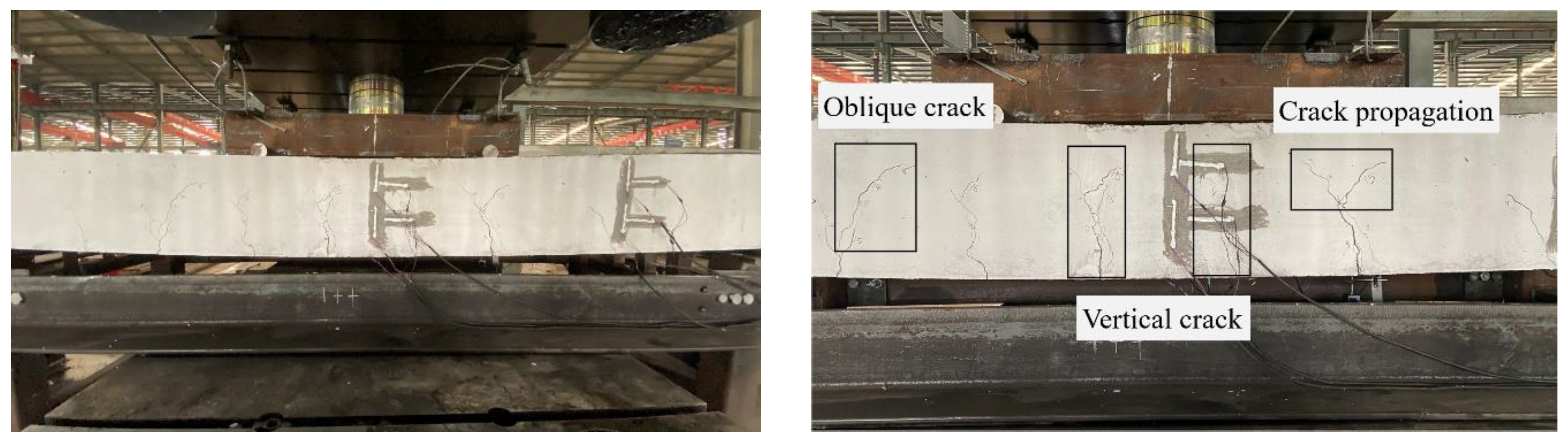
3.3.1. Experimental Phenomena
- (1)
- The BEJC50 × 6 component
- (2)
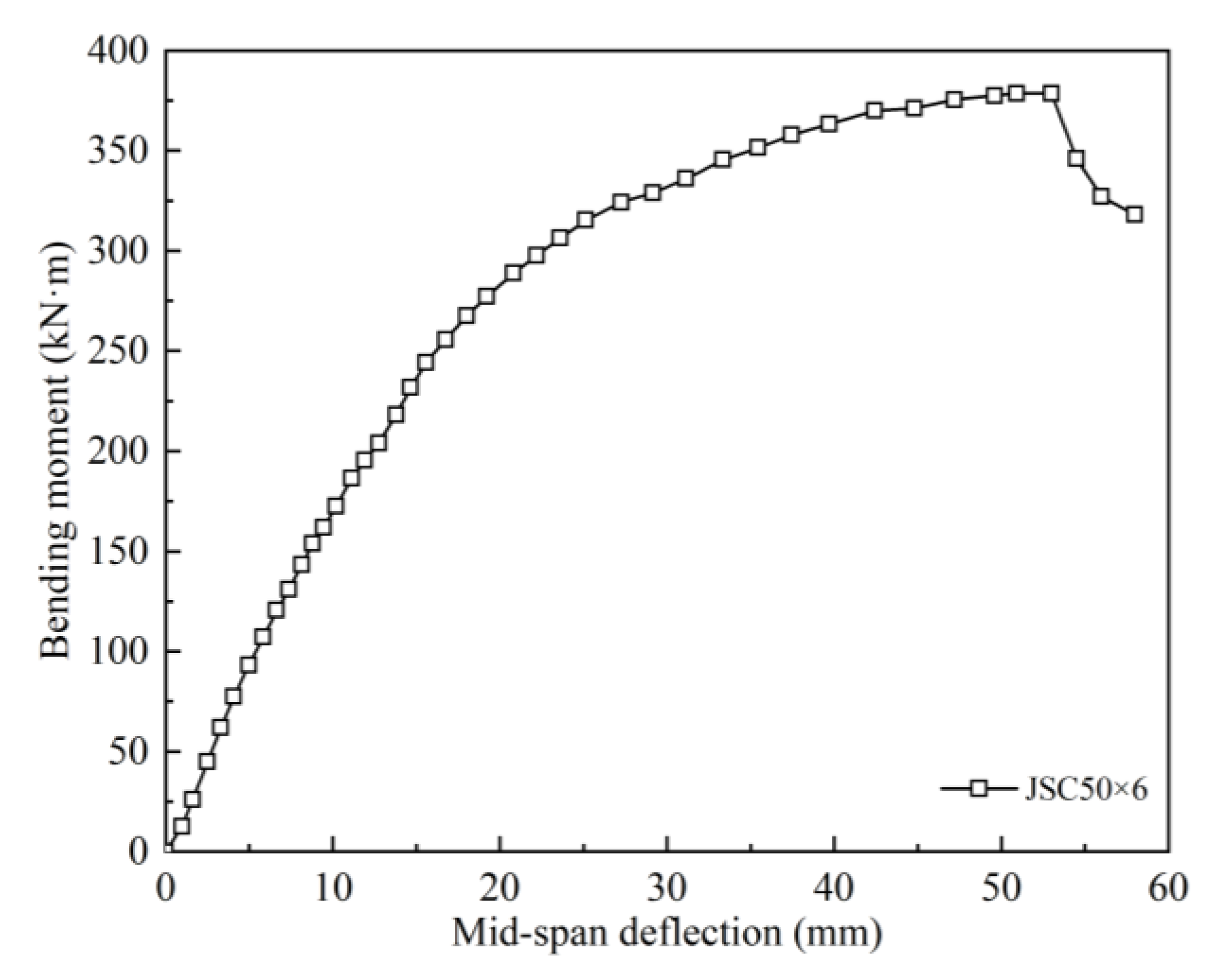
- The JSC50 × 6 component
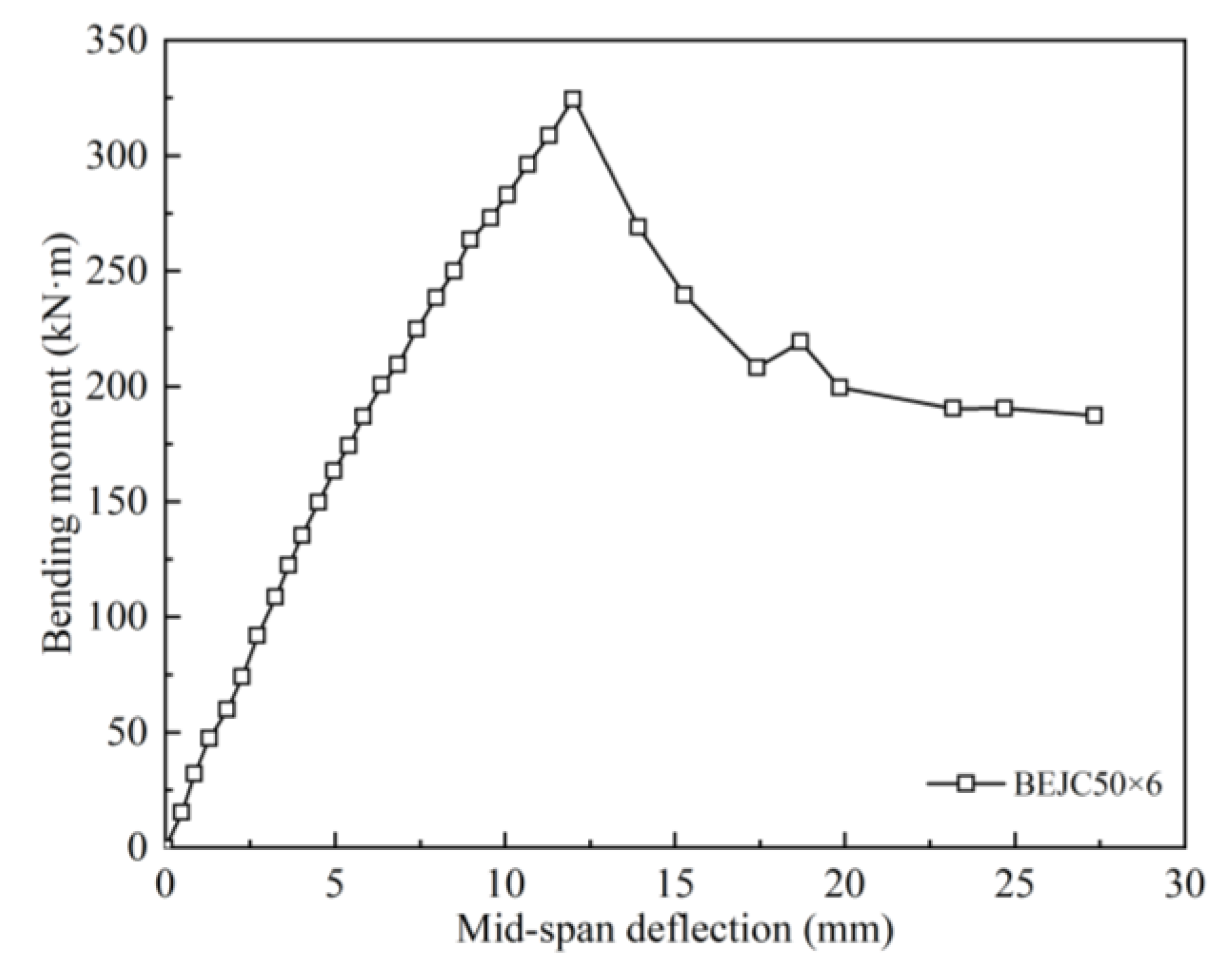
3.3.2. Deflection Displacement
- (1)
- The BEJC50 × 6 component
- (2)
- The JSC50 × 6 component
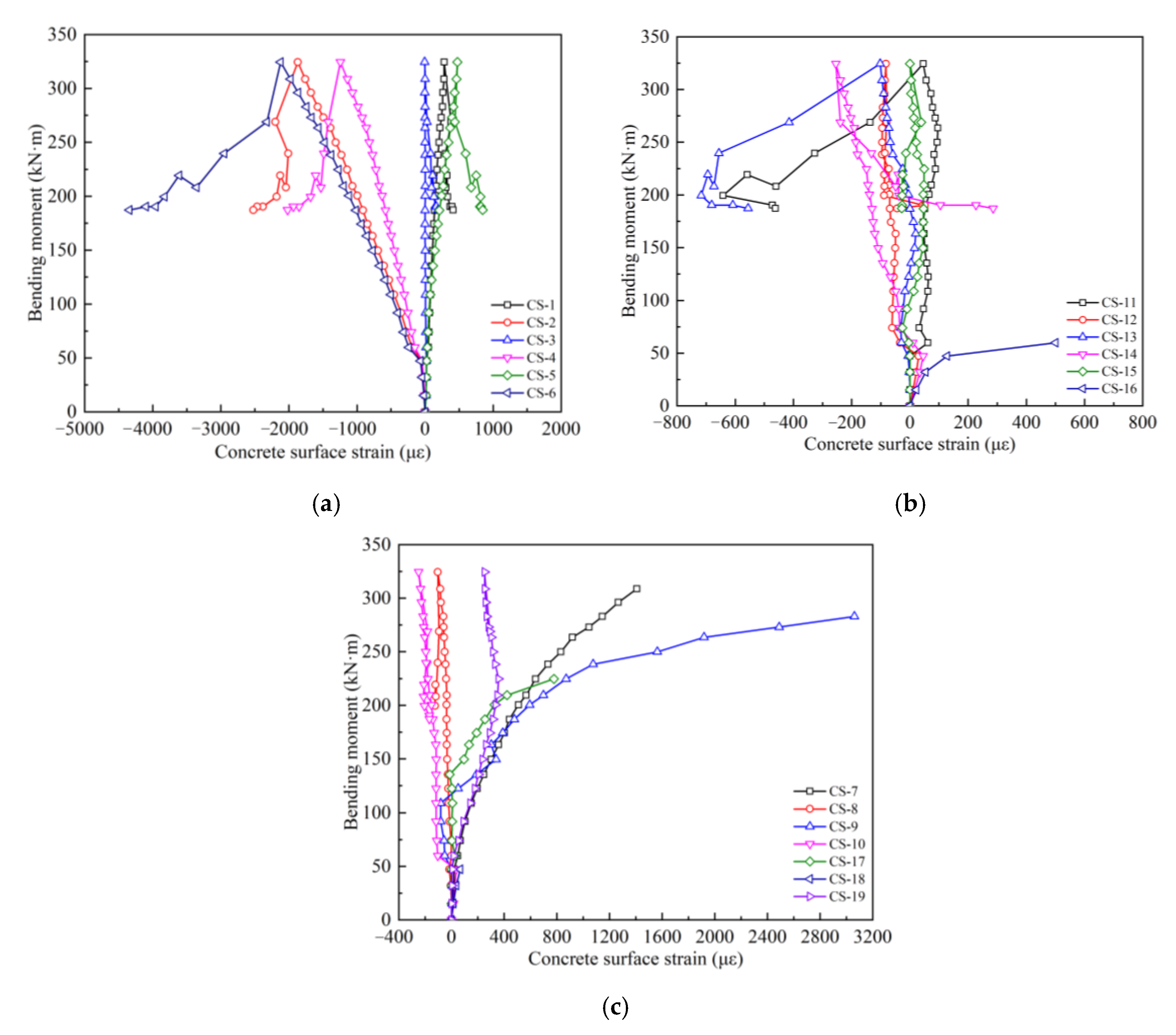
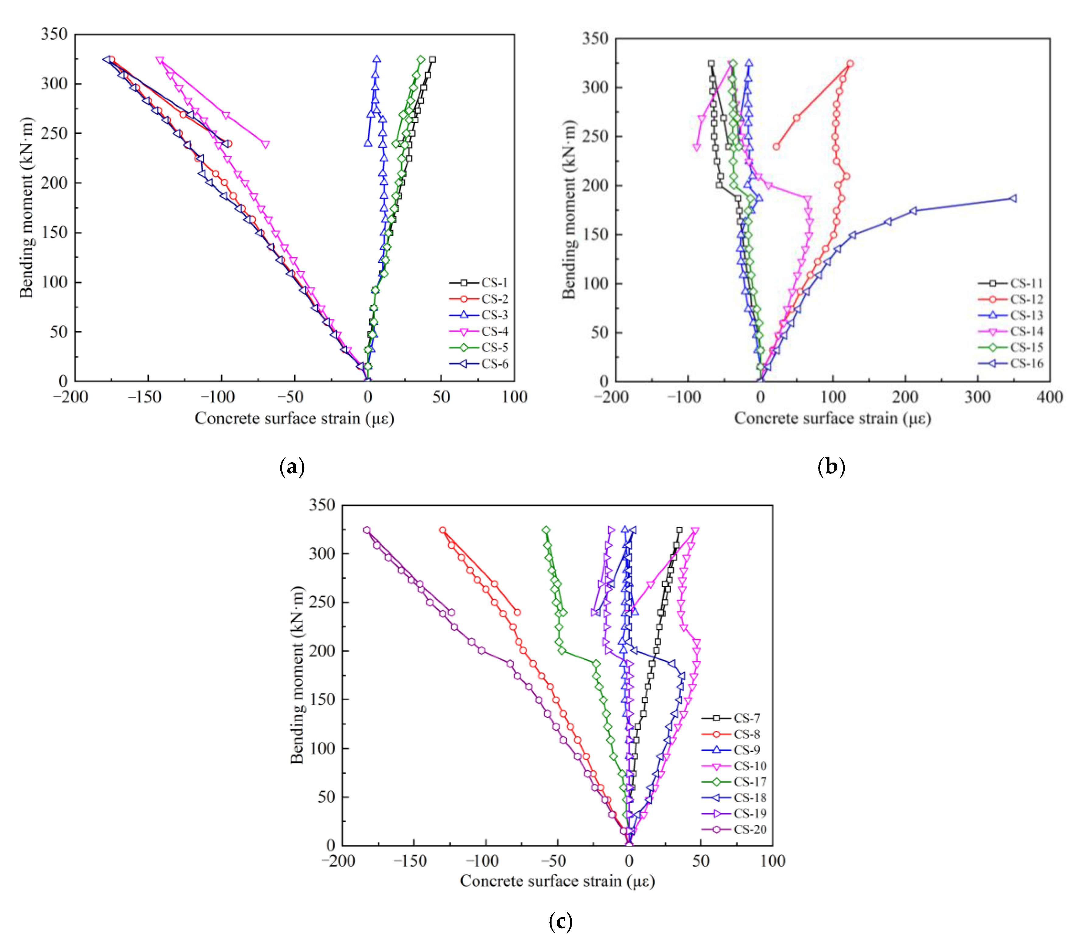
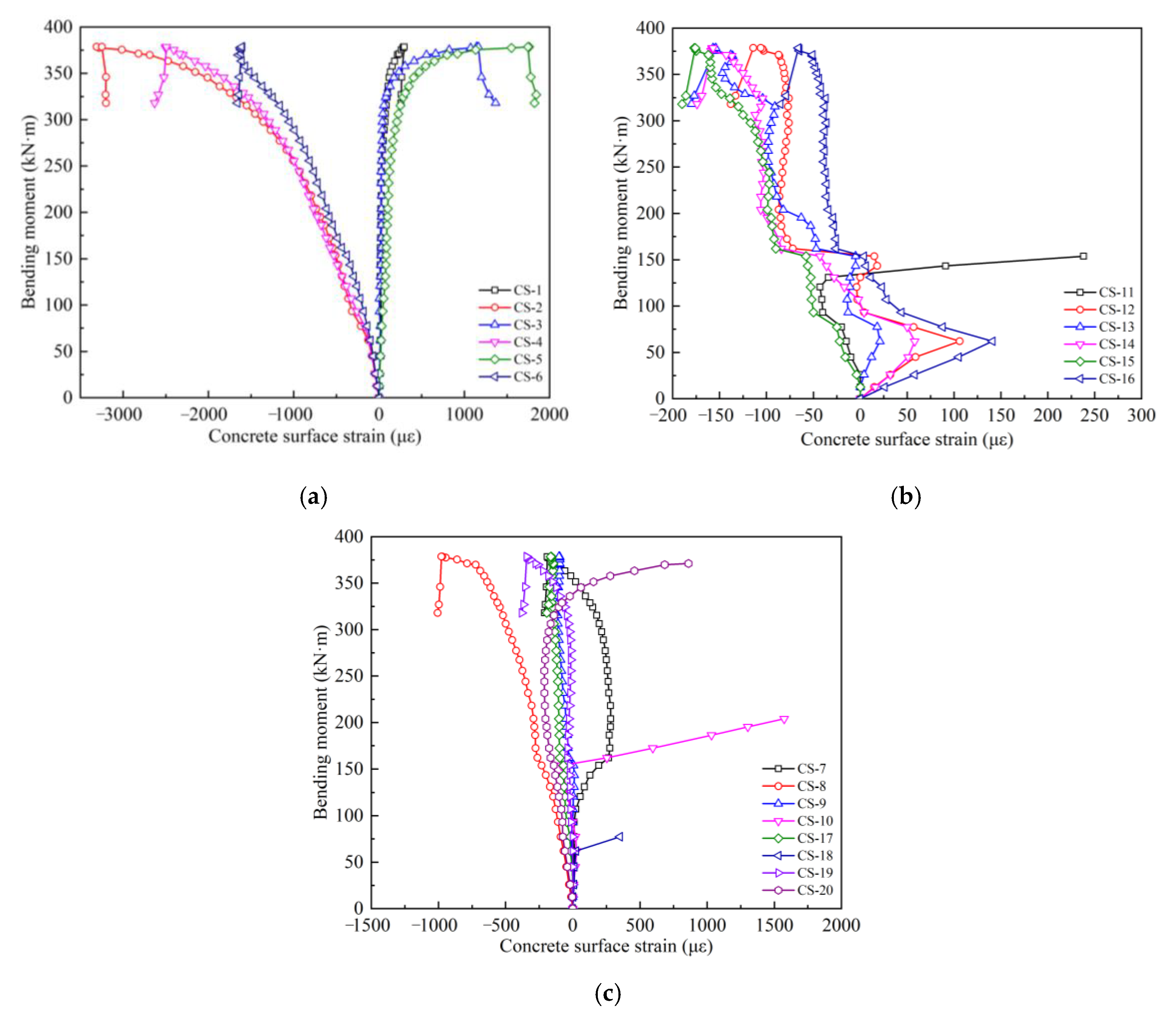
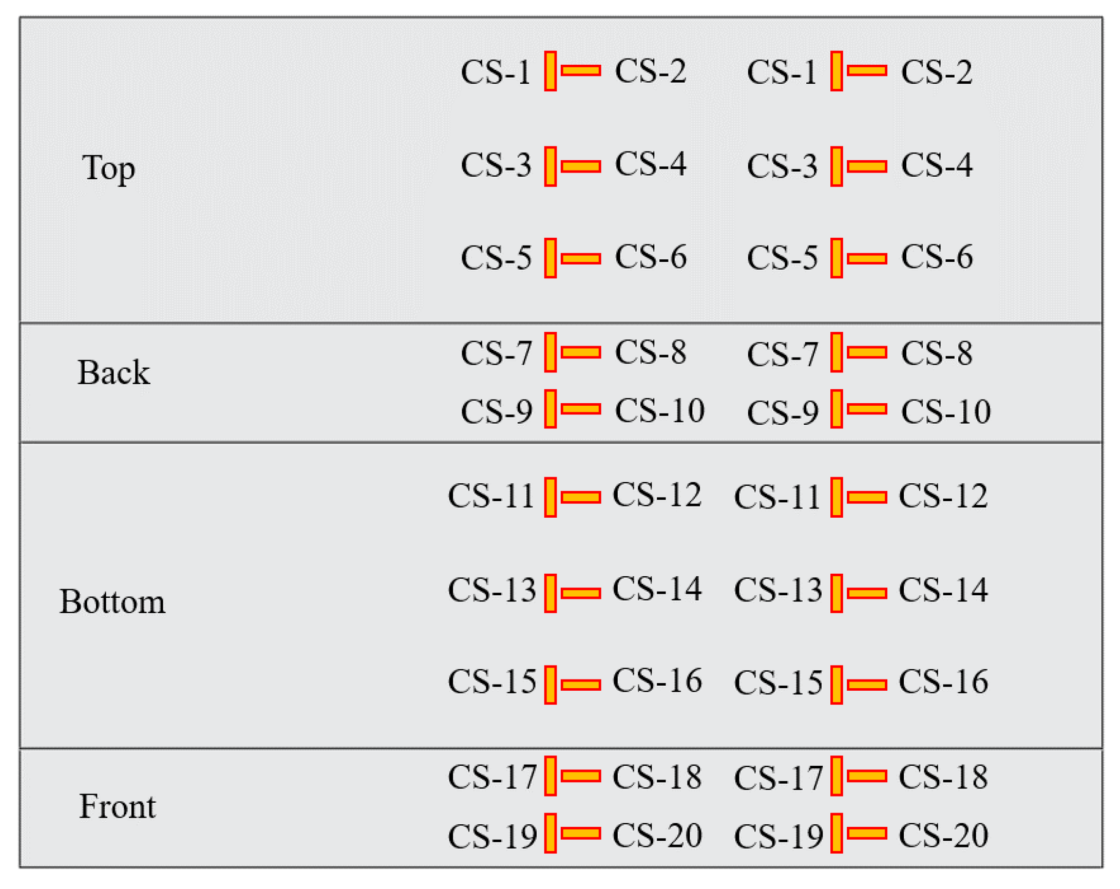
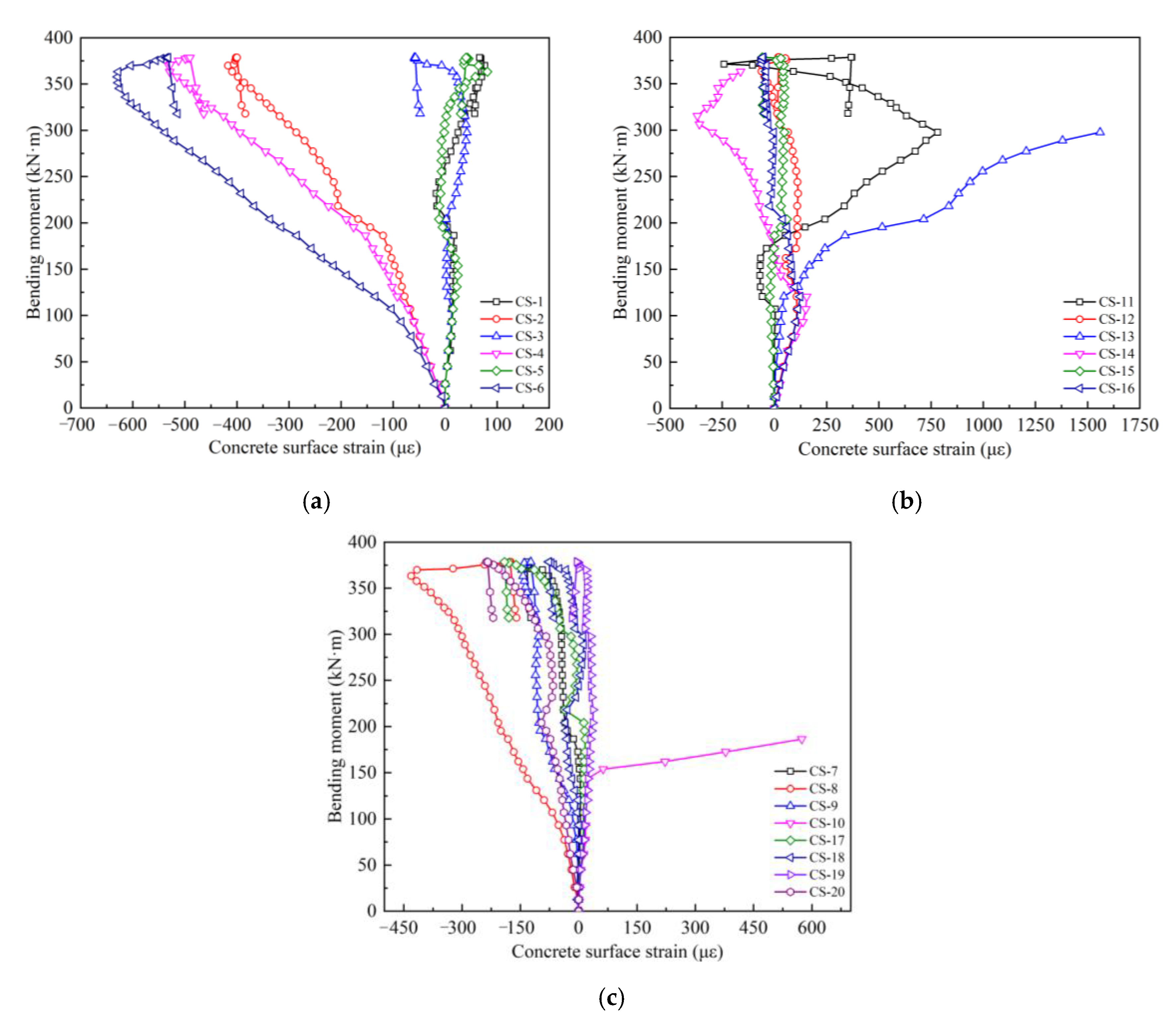
3.3.3. Concrete Strain
- (1)
- The BEJC50 × 6 component
- (2)
- The JSC50 × 6 component
4. Simulation Analysis of the Spatial Reticulated Grid Structure Segmentation and Snatch Assembly
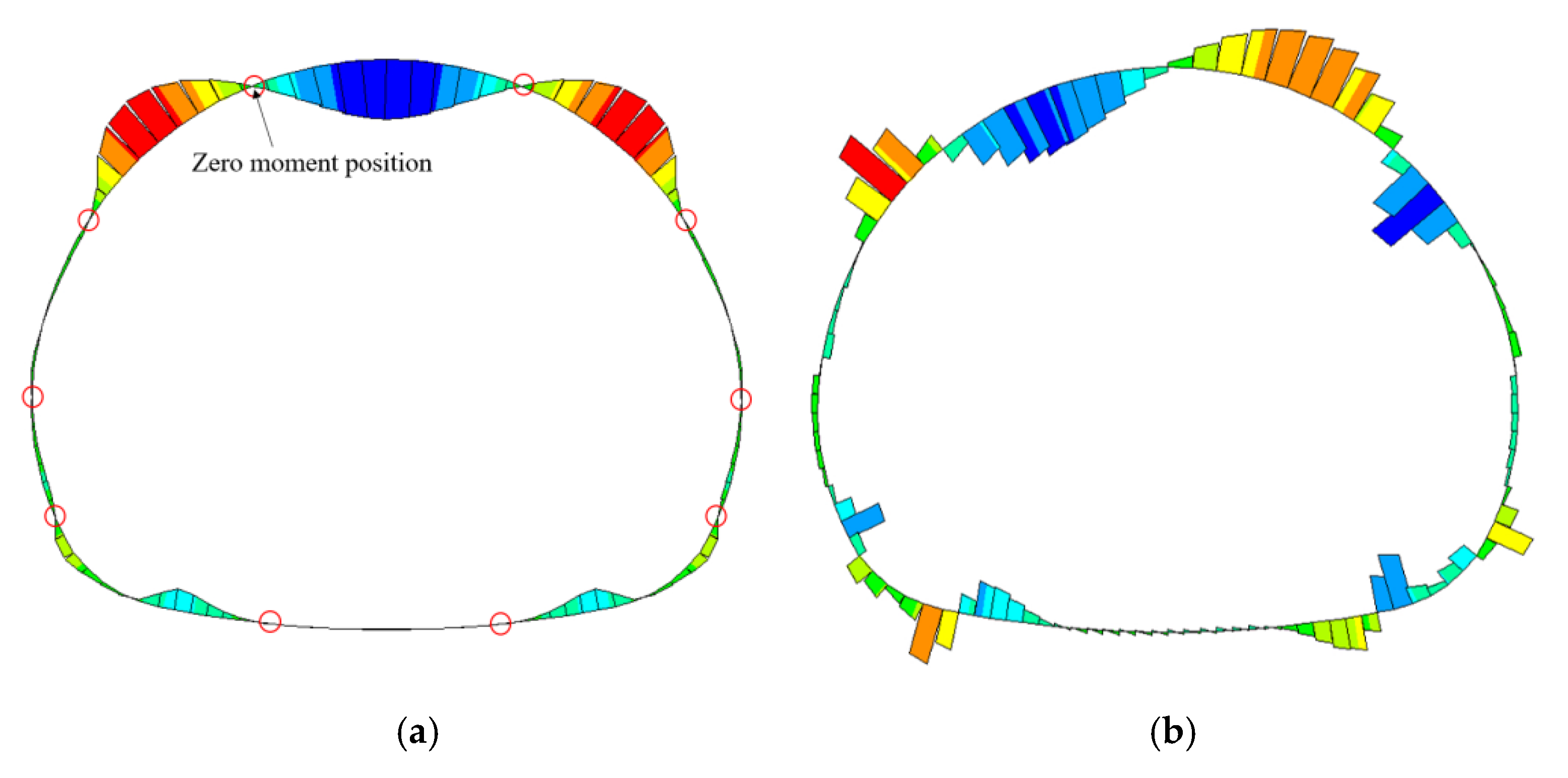
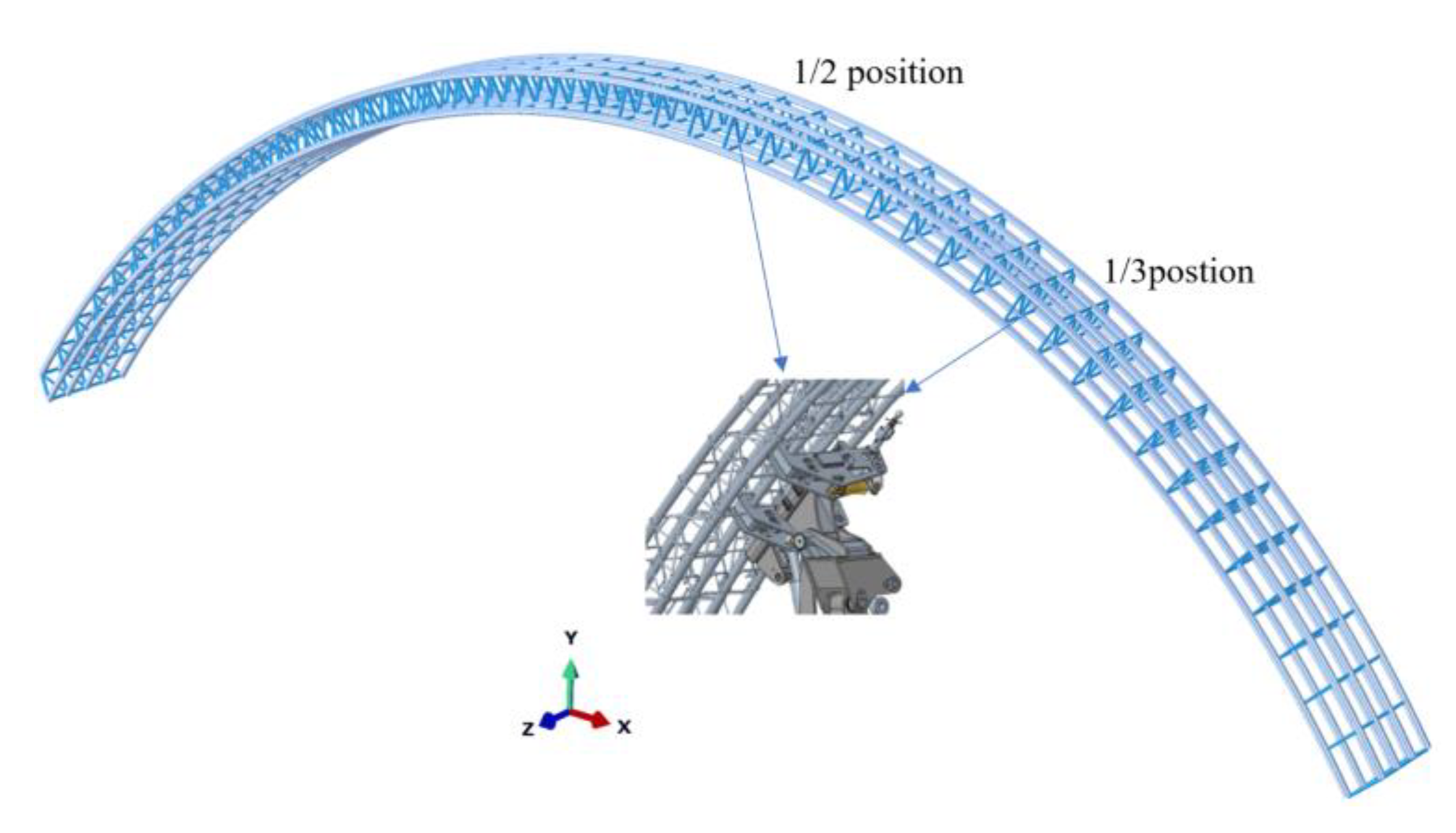
4.1. Determination of the Joint Position of the Spatial Reticulated Grid
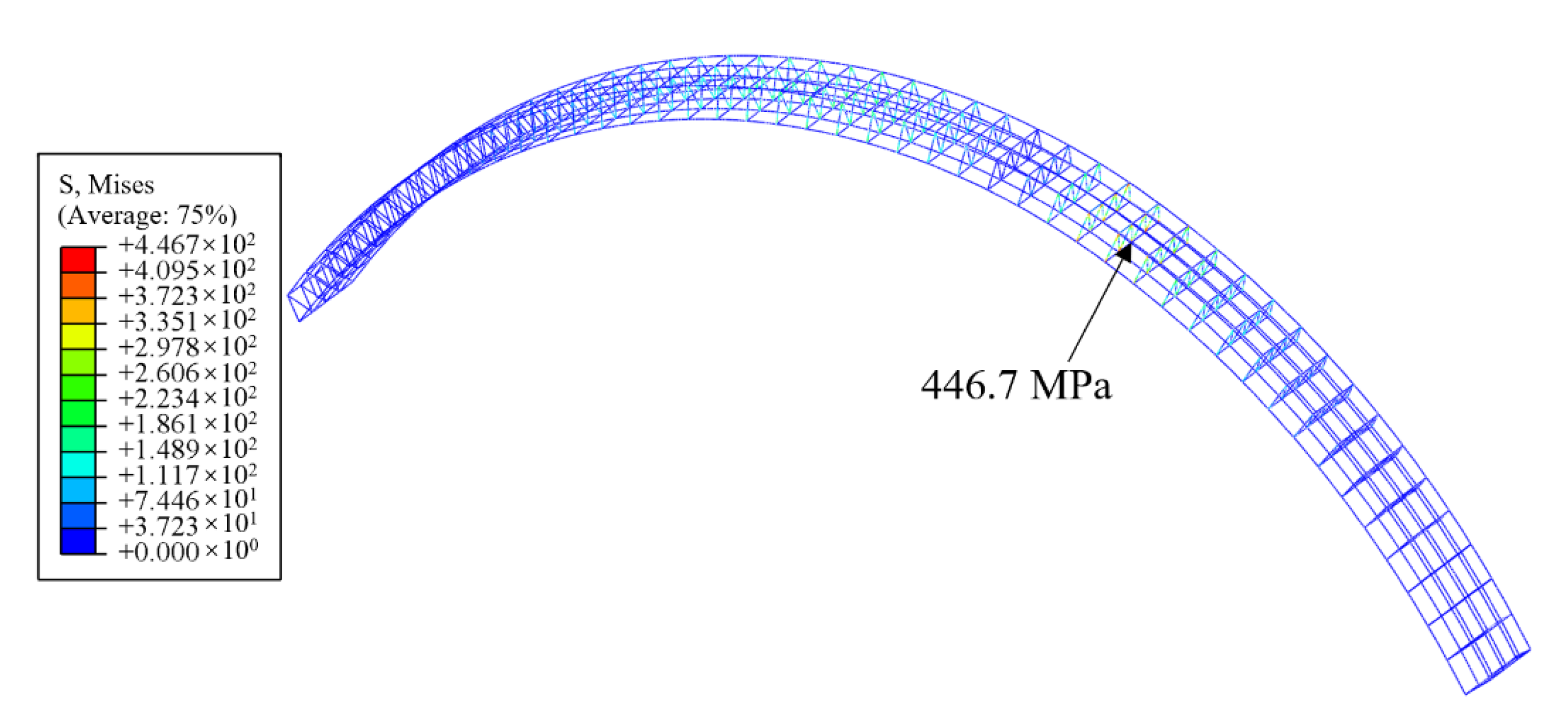
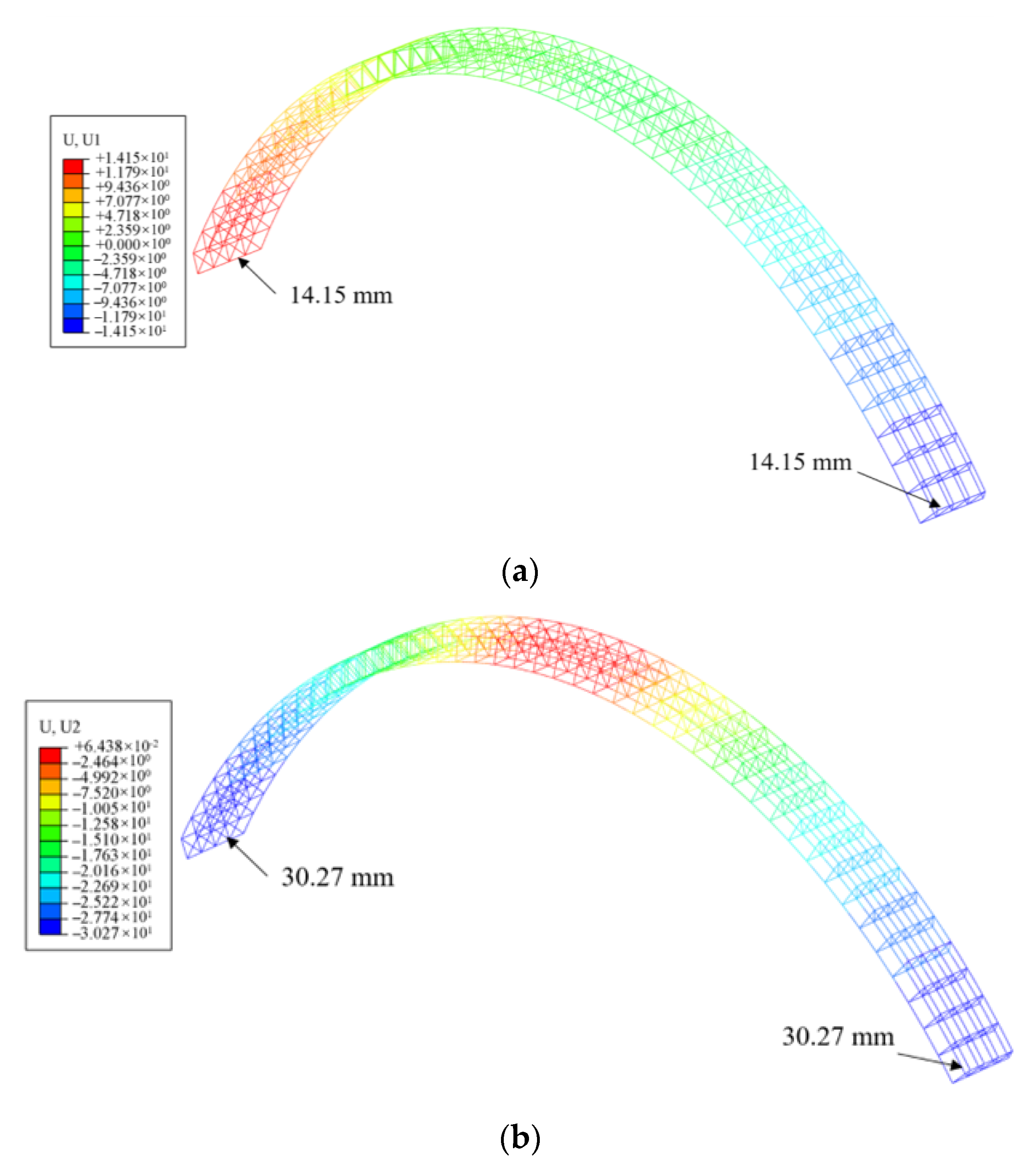
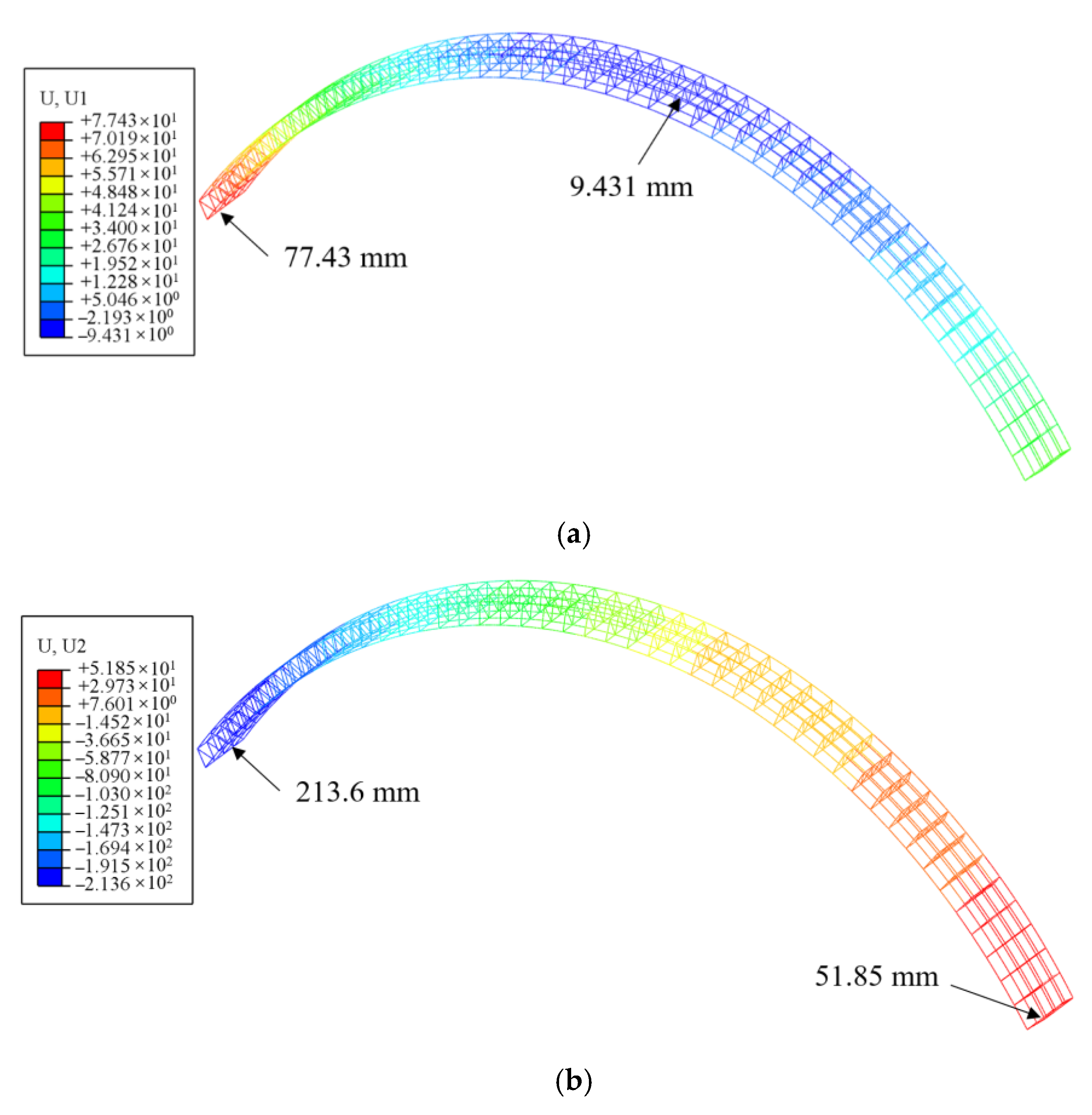
4.2. Simulation Analysis of Deformation and Force in the Snatch Process of the Spatial Reticulated Grid
4.2.1. Numerical Calculation Model
4.2.2. Analysis of the Simulation Results
- (1)
- 1/2 position
- (2)
- 1/3 position
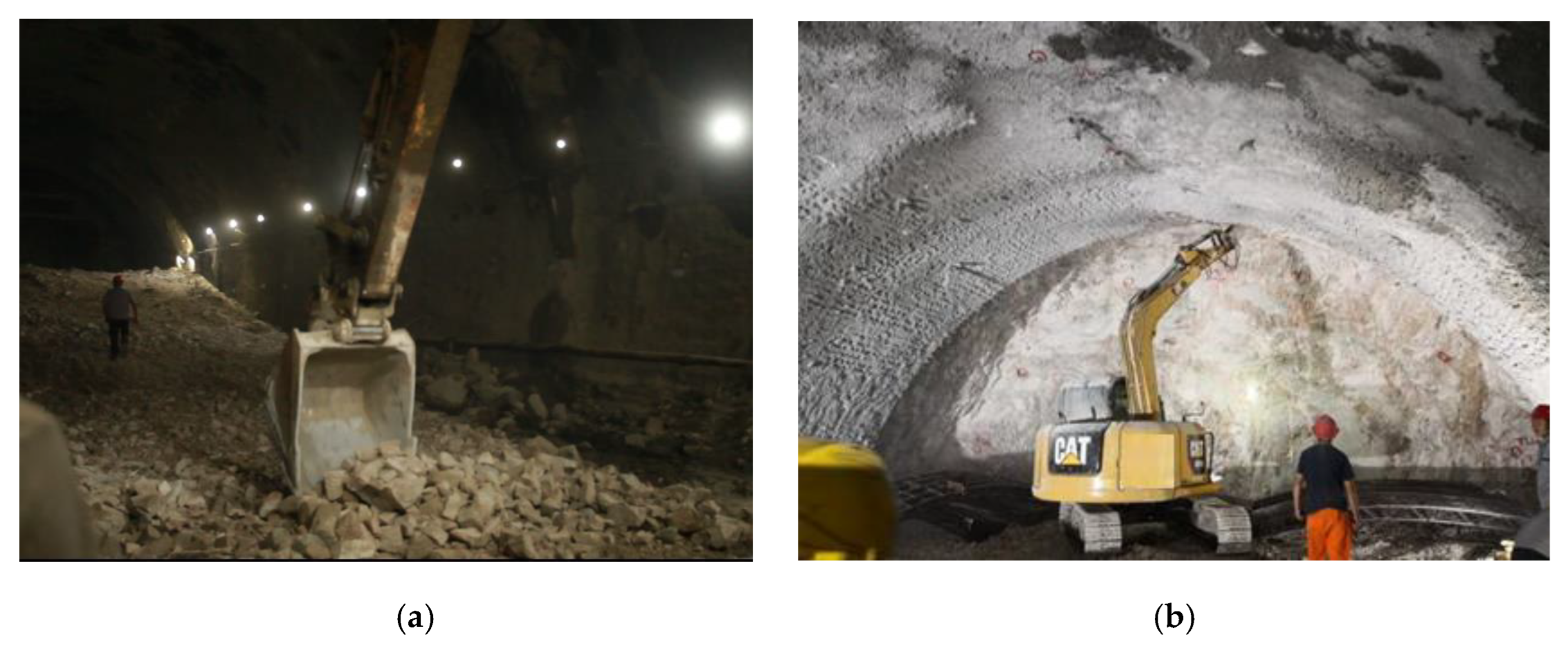
5. Field Application and Monitoring Analysis
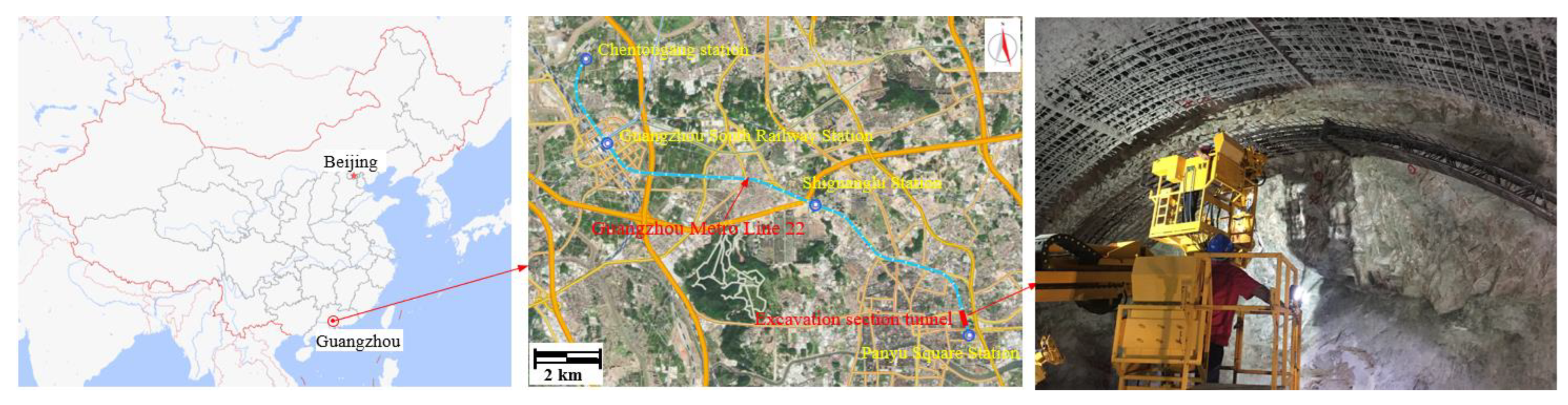
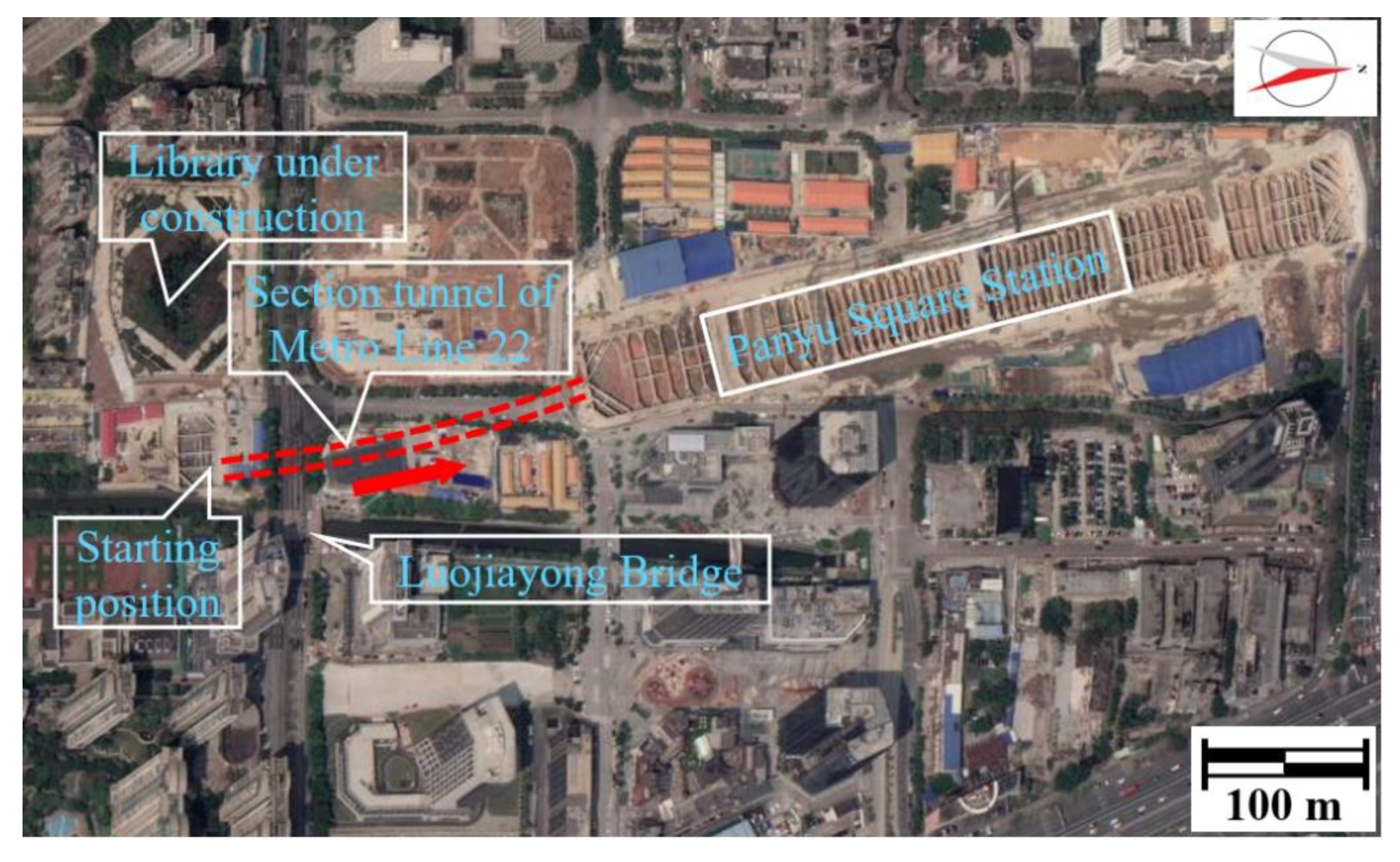
5.1. Project View
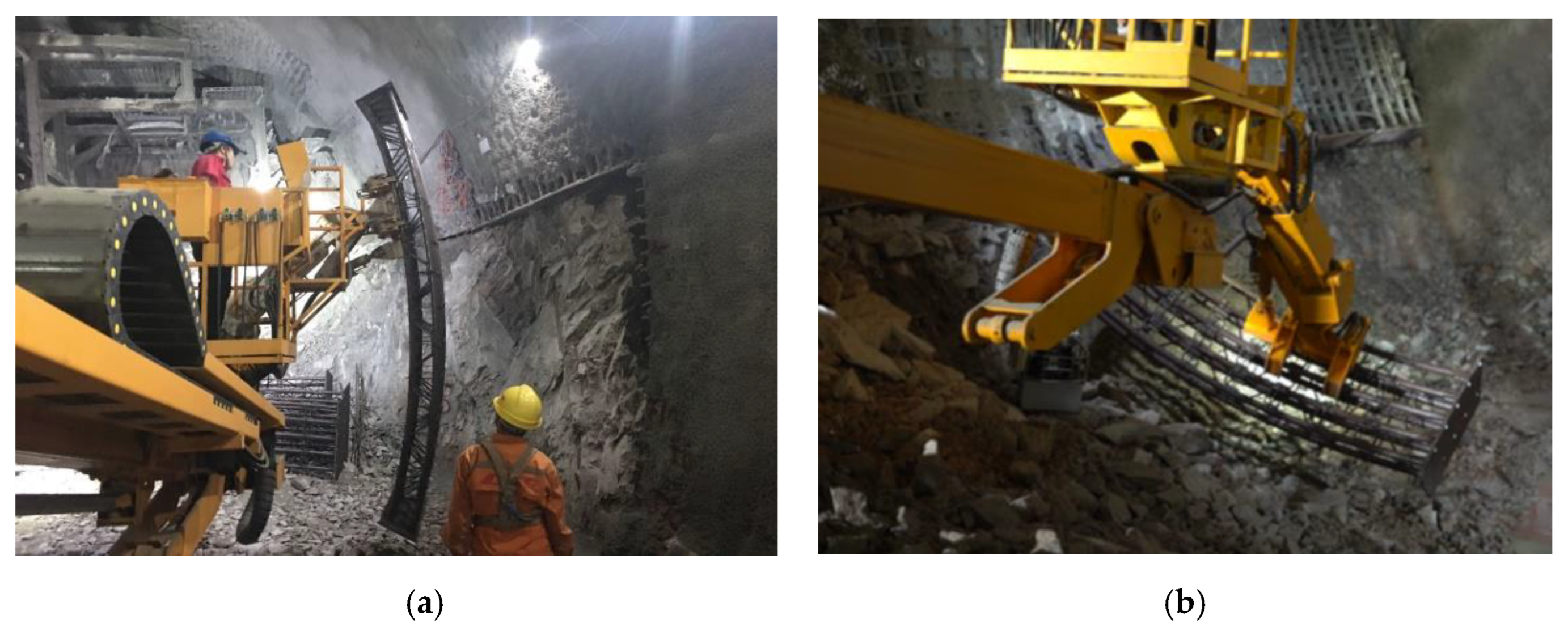
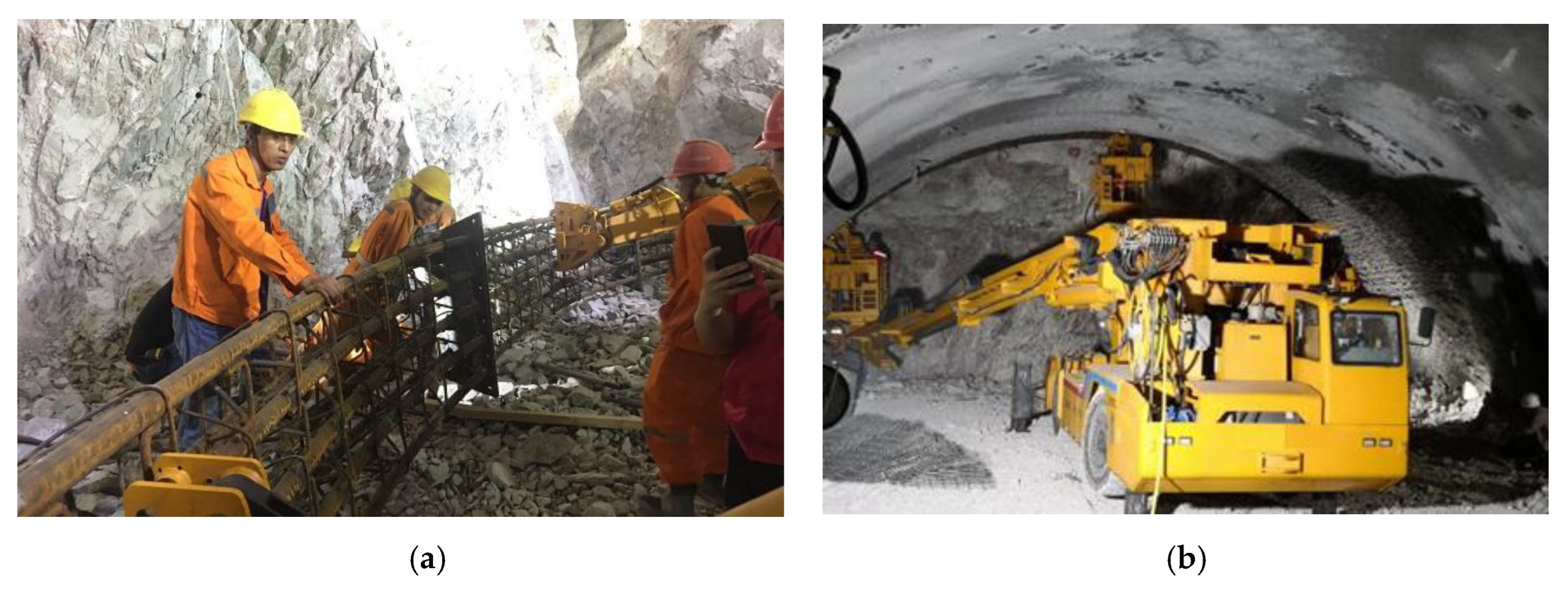
5.2. On-Site Mechanized Installation Process
- (1)
- The preparation before construction
- (2)
- Mechanized installation
- (3)
- Other processes
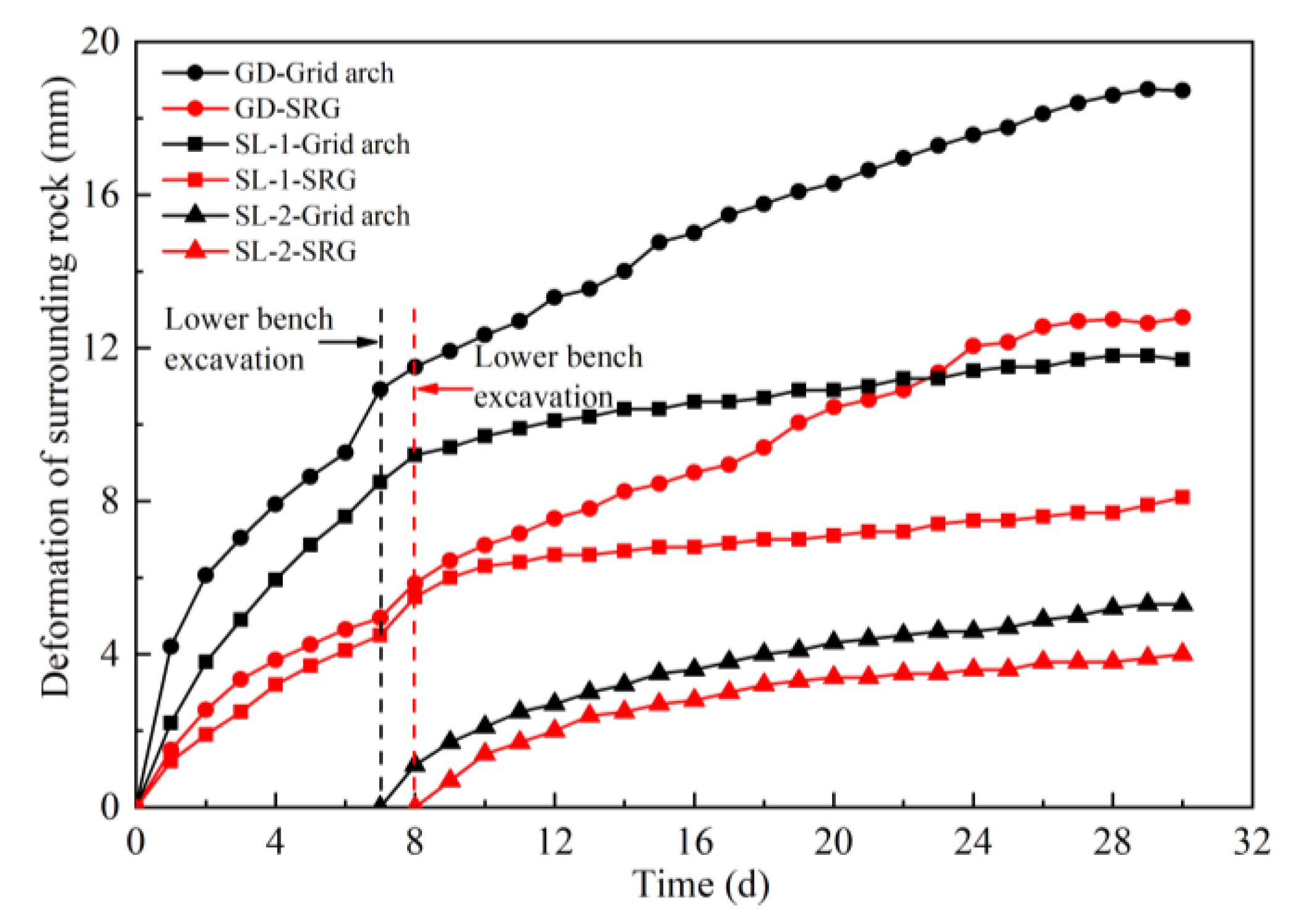
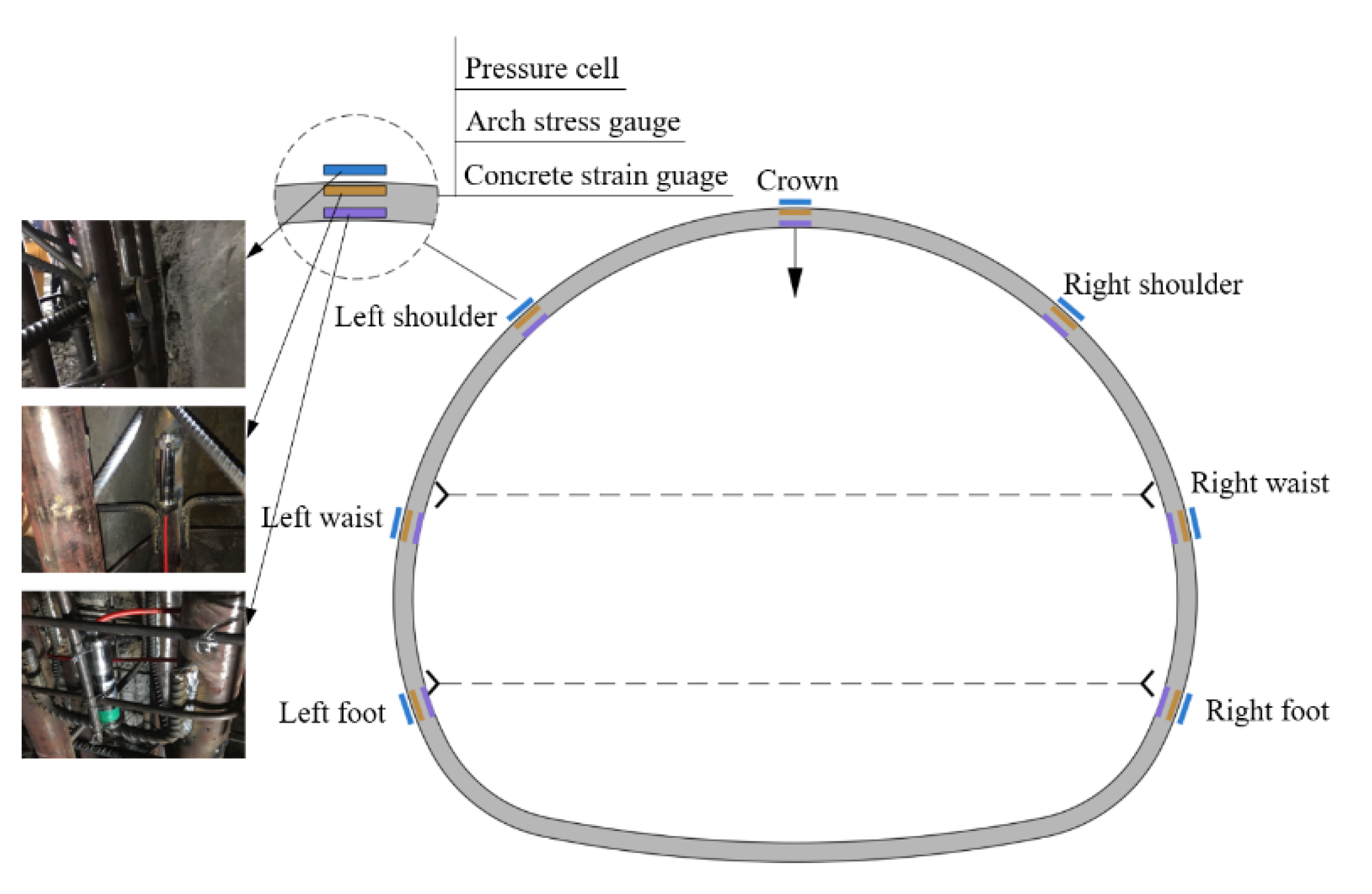
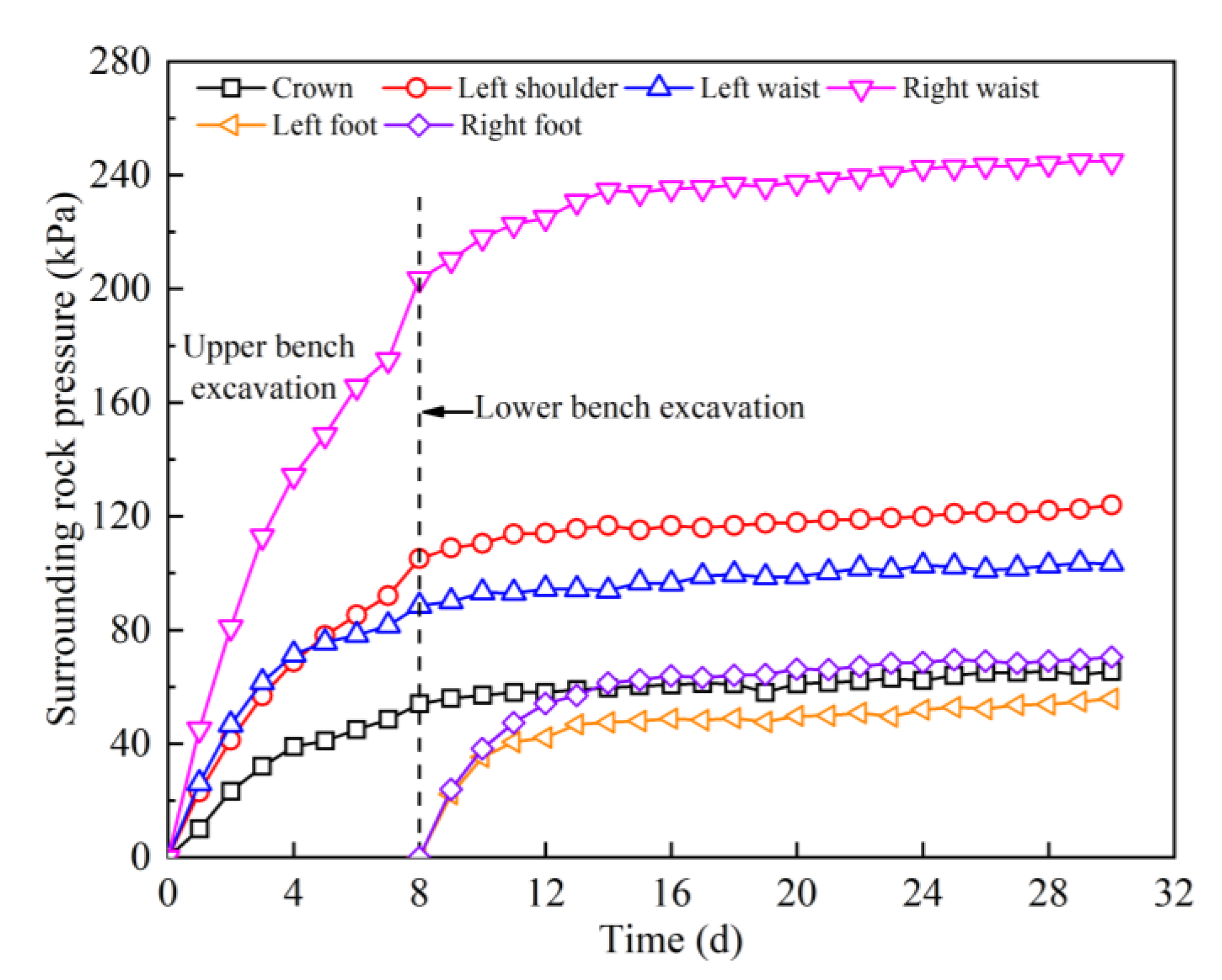
5.3. Analysis of Engineering Application Effect
6. Conclusions
- (1)
- In view of the problems of high risk and strict deformation control in the construction of large cross-section underground tunnels in complex urban environments, the concept of “timely high-strength support” was put forward, in which the initial support should form strong support over time and bear the surrounding rock load in real time.
- (2)
- The indoor local full-scale performance tests were carried out around the concrete components with bolted end-plate joints and without joints. The failure modes and bearing characteristics of the two types of flexural components were obtained, and the law of the influence of the joint structure on the bearing performance of the components was revealed. Compared with the jointless concrete component, the bolted end-plate joint concrete component had higher flexural rigidity, and the jointless concrete component had higher ultimate bearing capacity and better deformability.
- (3)
- The simulation analysis of deformation and force in the snatch process of the prefabricated spatial reticulated grid was carried out, and the field test was conducted with the help of the multi-functional operation trolley, which verified the feasibility and superiority of the mechanized construction. The first successful application of the SRGB support structure in the underground tunnel of the Guangzhou metro realized the deformation control and efficient support of the large-section tunnel in the high-density area of the city, enriched the support structure system of the underground tunnel in China, and could provide a reference for similar engineering processes in the future.
Author Contributions
Funding
Institutional Review Board Statement
Informed Consent Statement
Data Availability Statement
Conflicts of Interest
References
- Zhou, Z.; Zhang, J.J.; Gong, C.J. Automatic detection method of tunnel lining multi-defects via an enhanced You Only Look Once network. Comput. Aided Civ. Infrastruct. Eng. 2022, 37, 762–780. [Google Scholar] [CrossRef]
- Keawsawasvong, S.; Ukritchon, B. Design equation for stability of a circular tunnel in anisotropic and heterogeneous clay. Undergr. Space 2022, 7, 76–93. [Google Scholar] [CrossRef]
- Keawsawasvong, S.; Ukritchon, B. Design equation for stability of shallow unlined circular tunnels in Hoek-Brown rock masses. Bull. Eng. Geol. Environ. 2020, 79, 1–24. [Google Scholar] [CrossRef]
- Sirimontree, S.; Keawsawasvong, S.; Ngamkhanong, C.; Seehavong, S.; Sangjinda, K.; Jearsiripongkul, T.; Thongchom, C.; Nuaklong, P. Neural network-based prediction model for the stability of unlined elliptical tunnels in cohesive-frictional soils. Buildings 2022, 12, 444. [Google Scholar] [CrossRef]
- Baumann, T.; Betzle, M. Investigation of the performance of lattice girders in tunnelling. Rock Mech. Rock Eng. 1984, 17, 67–81. [Google Scholar] [CrossRef]
- Nomikos, P.P.; Sofianos, A.I.; Sakkas, K.M.; Choumanidis, D.; Delendas, S. Nonlinear simulation of lattice girder segment tests. Tunn. Undergr. Space Technol. 2013, 38, 180–188. [Google Scholar] [CrossRef]
- Kim, H.J.; Song, K.I.; Jung, H.S.; Shin, Y.W.; Shin, J.H. Performance evaluation of lattice girder and significance of quality control. Tunn. Undergr. Space Technol. 2018, 82, 482–492. [Google Scholar] [CrossRef]
- Lee, J.W.; Min, K.N.; Jeong, J.W.; Roh, B.K.; Lee, S.J.; Ahn, T.B.; Kang, S.S. Development of high strength lattice girder and evaluation of its performance. J. Eng. Geol. 2020, 30, 43–57. [Google Scholar]
- Kim, S.; Han, T.H.; Baek, J.S.; Kang, Y.J. Evaluation of the Structural Performance of Tetragonal Lattice Girders. Int. J. Steel Struct. 2013, 13, 31–47. [Google Scholar] [CrossRef]
- Qiu, W.G.; Lu, F.; Wang, G.; Huang, G.; Zhang, H.J.; Zhang, Z.Y.; Gong, C. Evaluation of mechanical performance and optimization design for lattice girders. Tunn. Undergr. Space Technol. 2019, 87, 100–111. [Google Scholar] [CrossRef]
- Tan, Z.S.; Han, K.H. Experimental study on the application of heat-treated high-strength lattice girder in tunnel engineering. Symmetry 2019, 11, 1007. [Google Scholar] [CrossRef] [Green Version]
- Gong, C.J.; Ding, W.Q.; Mosalam, K.M.; Günay, S.; Soga, K. Comparison of the structural behavior of reinforced concrete and steel fiber reinforced concrete tunnel segmental joints. Tunn. Undergr. Space Technol. 2017, 68, 38–57. [Google Scholar] [CrossRef]
- Ding, W.Q.; Gong, C.J.; Mosalam, K.M.; Soga, K. Development and application of the integrated sealant test apparatus for sealing gaskets in tunnel segmental joints. Tunn. Undergr. Space Technol. 2017, 63, 54–68. [Google Scholar] [CrossRef]
- Wang, Q.; Luan, Y.C.; Jiang, B.; Li, S.C.; He, M.C.; Sun, H.B.; Qin, Q.; Lu, W. Study on key technology of tunnel fabricated arch and its mechanical mechanism in the mechanized construction. Tunn. Undergr. Space Technol. 2019, 83, 187–194. [Google Scholar] [CrossRef]
- Wang, J.; Hu, C.C.; Zuo, J.P.; Wang, B.; Mao, Q.F.; Ding, H.G.; Zhao, N.N. Mechanism of roadway floor heave and control technology in fault fracture zone. J. China Coal Soc. 2019, 44, 397–408. [Google Scholar]
- Song, Y.; Huang, M.L.; Zhang, X.D.; Li, Z.P.; Peng, X.X. Experimental and numerical investigation on bearing capacity of circumferential joint of new spatial steel tubular grid arch in mined tunnel. Symmetry 2020, 12, 2065. [Google Scholar] [CrossRef]
- Huang, M.L.; Song, Y.; Zhang, X.D. Research and application of a prefabricated spatial reticulated shell support system for large cross-section tunnel in a complex urban environment. Appl. Sci. 2022, 12, 5058. [Google Scholar] [CrossRef]
- Hisatake, M. Effects of steel fiber reinforced high-strength shotcrete in a squeezing tunnel. Tunn. Undergr. Space Technol. 2003, 18, 197–204. [Google Scholar] [CrossRef]
- Li, Z.J.; Guo, X.X.; Ma, Z.W.; Yang, T.L.; Xu, J.Q. Research status and high-strength pre-stressed primary (type) support system for tunnels with large deformation under squeezing conditions. Tunn. Constr. 2020, 40, 755–782. [Google Scholar]
- Luo, J.W.; Zhang, D.L.; Fang, Q.; Li, A.; Sun, Z.Y.; Cao, L.Q. Analytical study on pretensioned bolt-cable combined support of large cross-section tunnel. Sci. China Technol. Sci. 2020, 63, 1808–1823. [Google Scholar] [CrossRef]
- Sun, J.; Jiang, Y.; Wang, B.; Fan, Y. Nonlinear rheological properties and yielding support technology for large squeezing deformation of soft rock tunnel with high ground stress. Tunn. Constr. 2021, 41, 1627–1633. [Google Scholar]
- Wu, K.; Shao, Z.S.; Qin, S.; Wei, W.; Chu, Z.F. A critical review on the performance of yielding supports in squeezing tunnels. Tunn. Undergr. Space Technol. 2021, 115, 103815. [Google Scholar] [CrossRef]
- Kong, X.Y.; Chen, X.; Tang, C.A.; Sun, Z.R.; Hu, E.H. Study on large deformation control technology and engineering application of tunnel with high ground stress and weak broken surrounding rock. Struct. Eng. Int. 2020, 32, 1–9. [Google Scholar] [CrossRef]
- He, M.C.; Gong, W.L.; Wang, J.; Qi, P.; Tao, Z.G.; Du, S.; Peng, Y.Y. Development of a novel energy-absorbing bolt with extraordinarily large elongation and constant resistance. Int. J. Rock Mech. Min. Sci. 2014, 67, 29–42. [Google Scholar] [CrossRef]
- Zheng, Y.T.; Zhu, S.Y.; Li, S.L.; Song, R.C.; Guo, T. Testing research on a composite support system using bolts, shotcrete, mesh and arc plates for a tunnel in soft rock mass. Chin. J. Rock Mech. Eng. 1993, 12, 3–12. [Google Scholar]
- Chang, Q.L.; Zhou, H.Q.; Li, D.W.; Bai, J.B.; Hou, C.J. Stability Principle of Extremely Rigid Secondary Support for Soft and Broken Rock Roadway. J. Min. Saf. Eng. 2007, 24, 169–172+177. [Google Scholar]
- Liu, D.J.; Zuo, J.P.; Wang, J.; Zhang, T.L.; Liu, H.Y. Large deformation mechanism and concrete-filled steel tubular support control technology of soft rock roadway-A case study. Eng. Fail. Anal. 2020, 116, 104721. [Google Scholar] [CrossRef]
- Huang, W.P.; Yuan, Q.; Tan, Y.L.; Wang, J.; Liu, G.L.; Qu, G.L.; Li, C. An innovative support technology employing a concrete-filled steel tubular structure for a 1000-m-deep roadway in a high in situ stress field. Tunn. Undergr. Space Technol. 2018, 73, 26–36. [Google Scholar] [CrossRef]
- Wang, Z.C.; Du, K.; Xie, Y.L.; Su, X.L.; Shi, Y.F.; Li, X.; Liu, T. Buckling analysis of an innovative type of steel-concrete composite support in tunnels. J. Constr. Steel Res. 2021, 179, 106503. [Google Scholar] [CrossRef]
- Xu, F.; Li, S.C.; Zhang, Q.Q.; Li, L.P.; Shi, S.S.; Zhang, Q. A new type support structure introduction and its contrast study with traditional support structure used in tunnel construction. Tunn. Undergr. Space Technol. 2016, 63, 171–182. [Google Scholar] [CrossRef]
- Yao, W.J.; Pang, J.Y.; Zhang, J.S.; Liu, G.C. Key technique study of stability control of surrounding rock in deep chamber with large cross-section: A case study of the Zhangji coal mine in China. Geotech. Geol. Eng. 2020, 39, 299–316. [Google Scholar] [CrossRef]
- Li, C.; Wang, Z.L.; Liu, T. Principle and practice of coupling support of double yielding shell of soft rock roadway under high stress. Int. J. Min. Sci. Technol. 2014, 24, 513–518. [Google Scholar] [CrossRef]
- TB-10003; Code for Design of Railway Tunnel. China Railway Publishing House: Beijing, China, 2016.


| Component Type | Length (mm) | Width (mm) | Height (mm) | Concrete Grade | Steel Tube Size (mm) | End-Plate Thickness (mm) | π-Shaped or U-Shaped Rebar Diameter (mm) | Bolt Size |
|---|---|---|---|---|---|---|---|---|
| BEJC50 × 6 component | 3200 | 1200 | 350 | C25 | 50 × 6 | 20 | 14 | M24 |
| JSC50 × 6 component | 3200 | 1200 | 350 | C25 | 50 × 6 | 14 |
| Material | Elastic Modulus (GPa) | Yield Strength (MPa) | Ultimate Tensile Strength (MPa) | Elongation Ratio (%) |
|---|---|---|---|---|
| 14 mm reinforcement | 198 | 430.34 | 576.81 | 23.60 |
| 20 mm thickness steel plate | 205 | 254.62 | 427.25 | 24.58 |
| 50 × 6 mm steel tube | 205 | 457.78 | 604.61 | 25.47 |
Publisher’s Note: MDPI stays neutral with regard to jurisdictional claims in published maps and institutional affiliations. |
© 2022 by the authors. Licensee MDPI, Basel, Switzerland. This article is an open access article distributed under the terms and conditions of the Creative Commons Attribution (CC BY) license (https://creativecommons.org/licenses/by/4.0/).
Share and Cite
Huang, M.; Song, Y.; Zhang, X.; Sun, T. Experimental Study and Engineering Application of the Spatial Reticulated Grid Bolt-Shotcrete Support Structure for Excavation Tunnels. Appl. Sci. 2022, 12, 8506. https://doi.org/10.3390/app12178506
Huang M, Song Y, Zhang X, Sun T. Experimental Study and Engineering Application of the Spatial Reticulated Grid Bolt-Shotcrete Support Structure for Excavation Tunnels. Applied Sciences. 2022; 12(17):8506. https://doi.org/10.3390/app12178506
Chicago/Turabian StyleHuang, Mingli, Yuan Song, Xudong Zhang, and Tong Sun. 2022. "Experimental Study and Engineering Application of the Spatial Reticulated Grid Bolt-Shotcrete Support Structure for Excavation Tunnels" Applied Sciences 12, no. 17: 8506. https://doi.org/10.3390/app12178506
APA StyleHuang, M., Song, Y., Zhang, X., & Sun, T. (2022). Experimental Study and Engineering Application of the Spatial Reticulated Grid Bolt-Shotcrete Support Structure for Excavation Tunnels. Applied Sciences, 12(17), 8506. https://doi.org/10.3390/app12178506