_Yang.png)

A Rule-Based Control Strategy of Driver Demand to Enhance Energy Efficiency of Hybrid Electric Vehicles


Abstract
:1. Introduction
2. Materials and Methodology
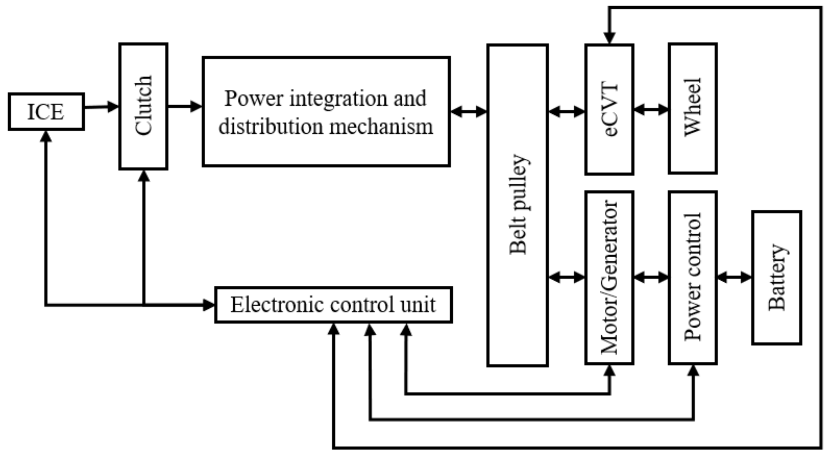
2.1. Device Architecture
2.2. Energy Management Control Strategy with Operation Mode
- (1)
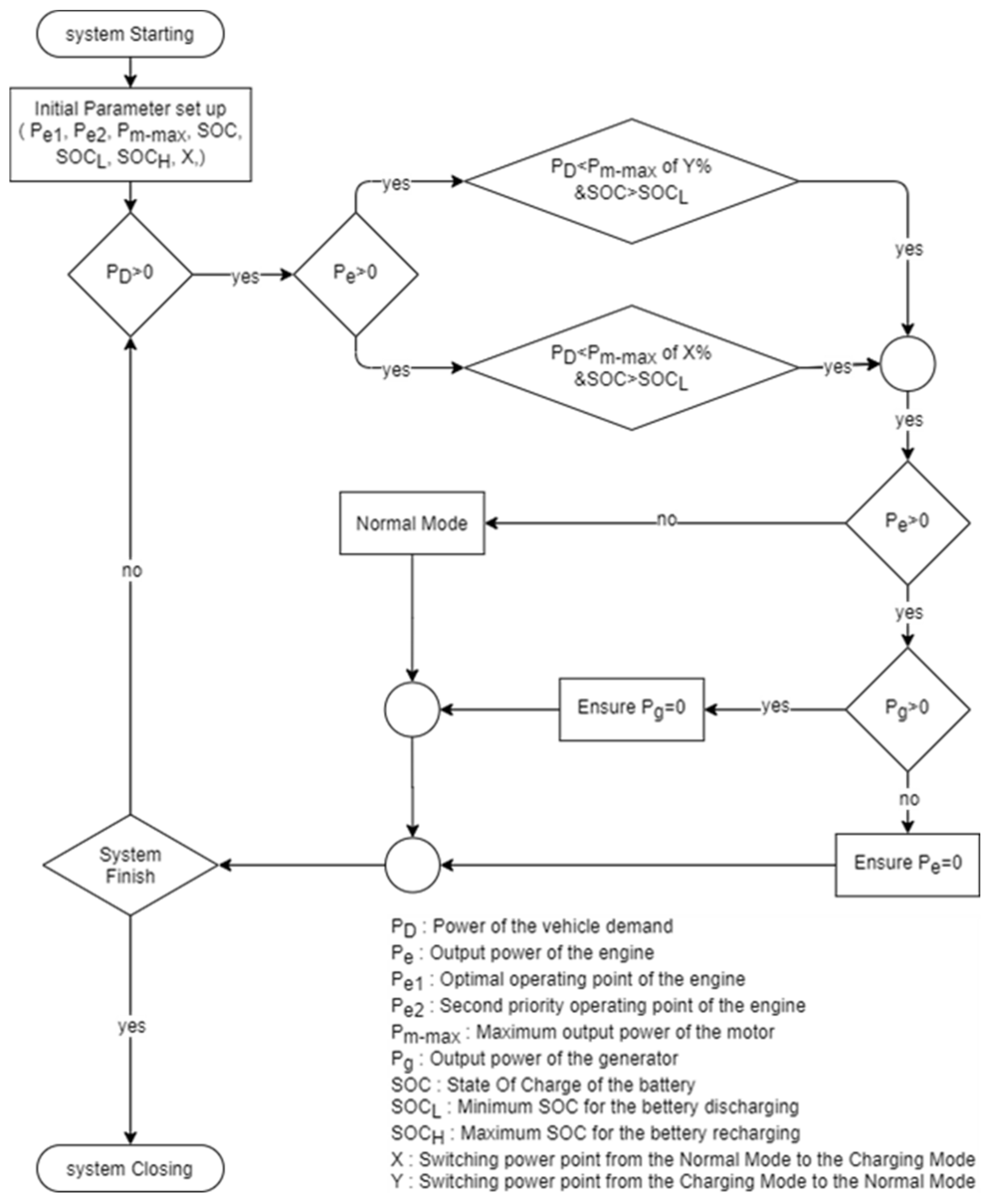
- Motor output: The control flow is shown in Figure 2. The operating mode switching point is determined according to the maximum power that the electric motor can output and the efficiency curve of the internal combustion engine. When the demand power does not exceed the switching value of the maximum output power of the electric motor, the electric motor provides power to meet the vehicle’s power demand. Conversely, when the required power exceeds the switching value of the maximum output power of the electric motor, it switches to the ICE mode. During the switching process, the ICE rises to the operating point established by the system in the shortest time. The operating point varies depending on the SOC. As the power output of the ICE rises, the energy management controller controls the output of the motor power. The driver does not feel the vibration caused by the engagement of the two power sources when the mode is switched, as shown in Figure 2.
- (2)
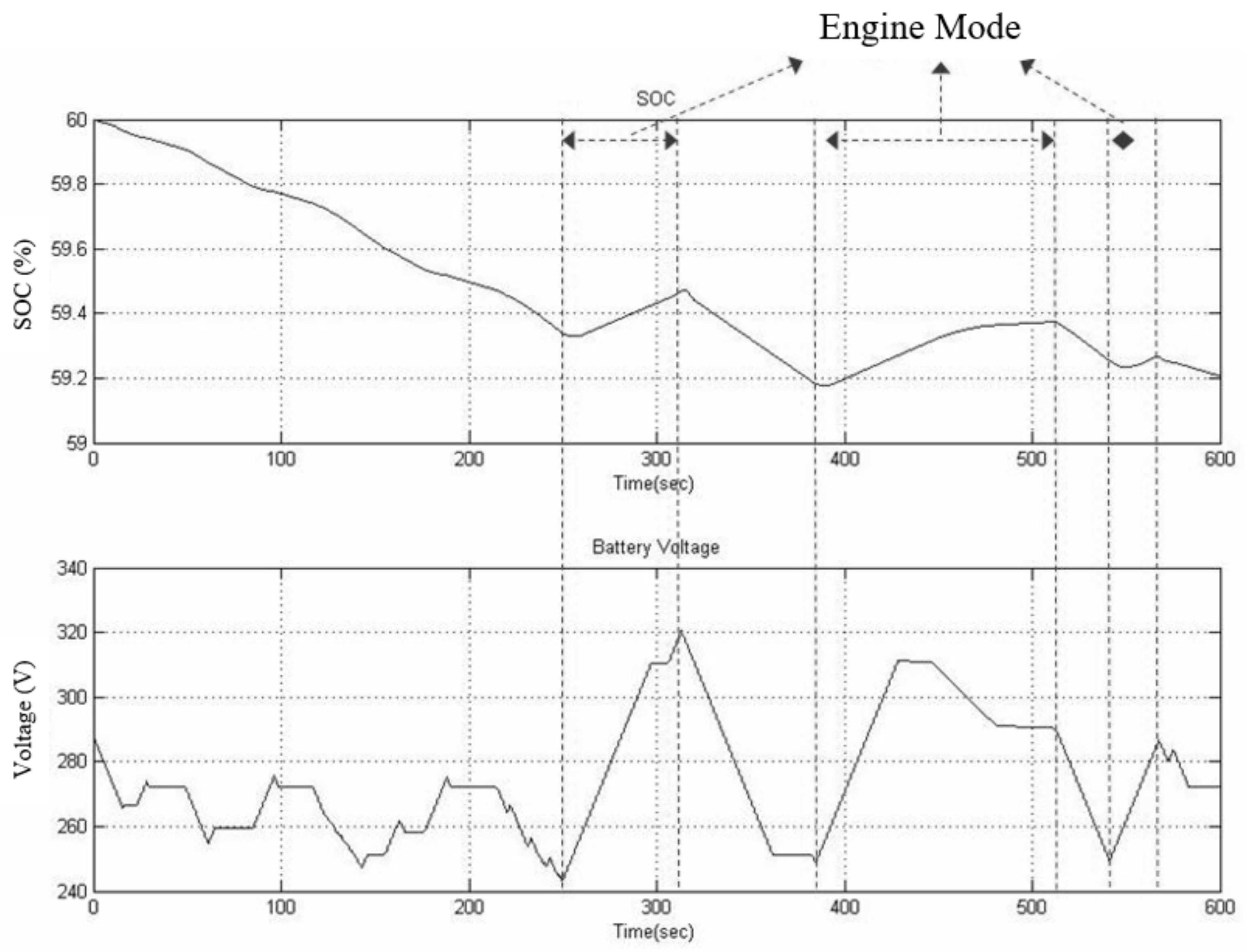
- Engine output: The control flow is shown in Figure 3. The ICE mode is activated when the driver′s power demand exceeds the switching value of the maximum output power of the electric motor and the SOC is also within the rechargeable range. This allows for excess power to be charged back to the battery using the generator. In addition, when the driver’s power demand exceeds the optimal operating point of the internal combustion engine, a transition from the generator state to the powering electric motor state occurs. Finally, the pure combustion engine mode can also charge the battery to the SOC reference value when the vehicle is under low load.
- (3)
- Dual output: The control flow is shown in Figure 4. When the driver’s power demand exceeds the optimal operating point of the ICE and the SOC is greater than the reference value, the electric motor is used to assist the ICE to meet the vehicle’s power demand.
- (4)
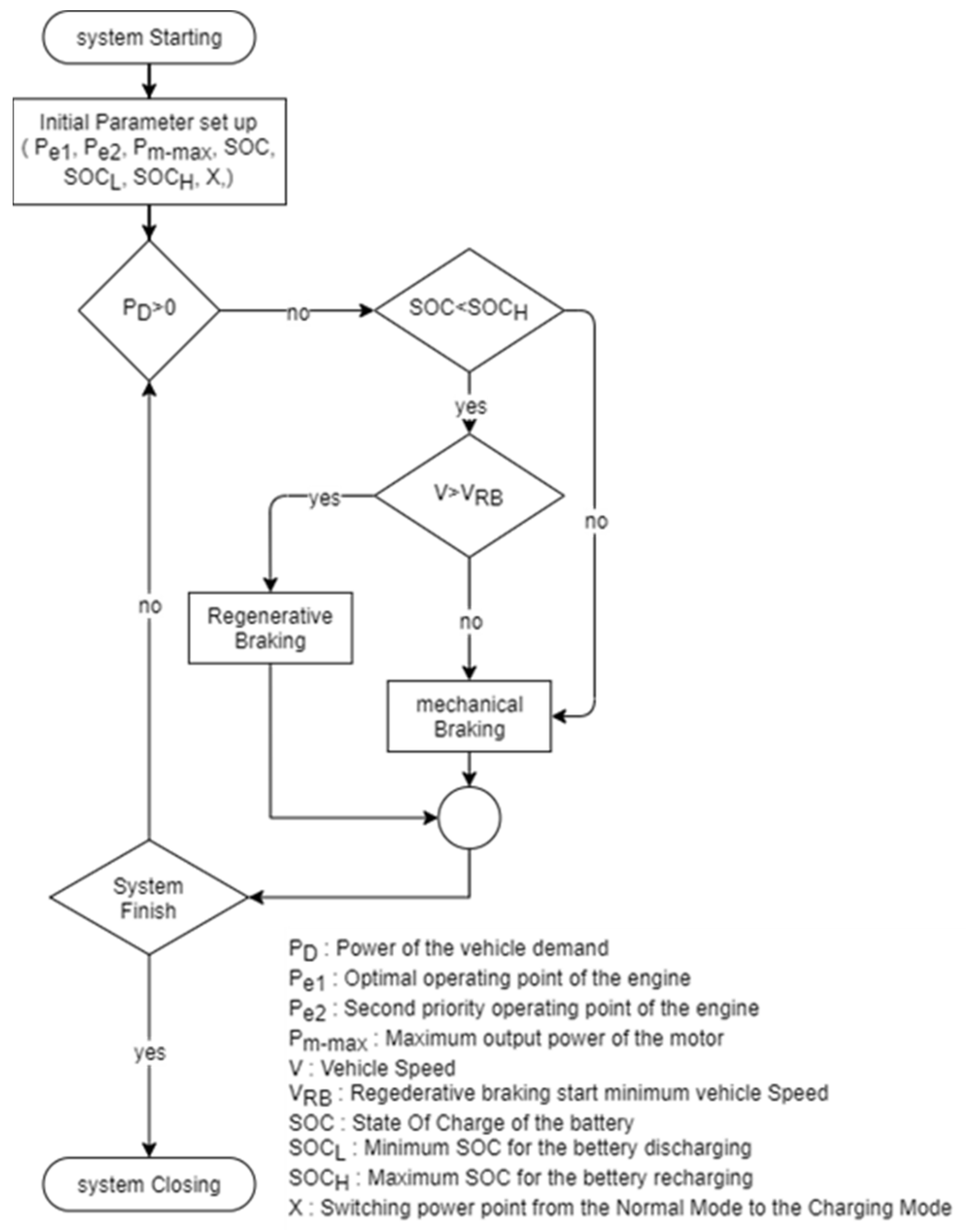
- Regenerative braking: The control flow is shown in Figure 5. When the driver depresses the brake pedal, the energy management controller determines that the system is in the deceleration mode. At this time, the ICE does not run and the electric motor is driven by the inertia of the vehicle to become a generator. If the SOC is already greater than the reference value, the pure braking mode is used without charging. Moreover, the vehicle speed is judged first. If the vehicle speed is greater than the switching value of regenerative braking, the electric motor is turned on to absorb the braking energy and recharge the battery.
3. Results and Discussion
4. Conclusions
- 1.
- The rule-based system coupled with the power integration and distribution mechanism achieves four energy management strategies, which are motor output, engine output, dual output, and regenerative braking.
- 2.
- The energy management control strategy takes into account all the conditions that may be encountered in driving. Introducing more power engagement modes can increase the smoothness of power delivery.
- 3.
- The control strategy based on the driver’s power demand is not only more rigorous in structure but also closer to the actual vehicle operation mode than speed based. This method effectively avoids the occurrence of unsmooth power switching.
- 4.
- Compared to traditional vehicles, HEVs can greatly save fuel consumption and reduce exhaust emissions. HEVs can meet low-carbon requirements and future carbon emission restrictions.
Author Contributions
Funding
Institutional Review Board Statement
Informed Consent Statement
Data Availability Statement
Conflicts of Interest
References
- Man, H.; Liu, H.; Xiao, Q.; Deng, F.; Yu, Q.; Wang, K.; Yang, Z.; Wu, Y.; He, K.; Hao, J. How ethanol and gasoline formula changes evaporative emissions of the vehicles. Appl. Energy 2018, 222, 584–594. [Google Scholar] [CrossRef]
- Ye, M.; Sharp, P.; Brandon, N.; Kucernak, A. System-level comparison of ammonia, compressed and liquid hydrogen as fuels for polymer electrolyte fuel cell powered shipping. Int. J. Hydrog. Energy 2022, 47, 8565–8584. [Google Scholar] [CrossRef]
- Nguyen, M.K.; Sangeetha, T.; Chen, P.-T.; Hsu, T.-W.; Yan, W.-M.; Yang, C.-J.; Huang, K.D. High performance zinc–air fuel cell with zinc particle fuel and flowing electrolyte. J. Chin. Inst. Eng. 2021, 44, 842–850. [Google Scholar] [CrossRef]
- Liu, K.; Li, K.; Peng, Q.; Zhang, C. A brief review on key technologies in the battery management system of electric vehicles. Front. Mech. Eng. 2019, 14, 47–64. [Google Scholar] [CrossRef]
- Wang, Q.; Jiang, B.; Li, B.; Yan, Y. A critical review of thermal management models and solutions of lithium-ion batteries for the development of pure electric vehicles. Renew. Sustain. Energy Rev. 2016, 64, 106–128. [Google Scholar] [CrossRef]
- Panchal, S.; Mathew, M.; Dincer, I.; Agelin-Chaab, M.; Fraser, R.; Fowler, M. Thermal and electrical performance assessments of lithium-ion battery modules for an electric vehicle under actual drive cycles. Electr. Pow. Syst. Res. 2018, 163, 18–27. [Google Scholar] [CrossRef]
- Lu, M.; Zhang, X.; Ji, J.; Xu, X.; Zhang, Y. Research progress on power battery cooling technology for electric vehicles. J. Energy Storage 2020, 27, 101155. [Google Scholar] [CrossRef]
- Martinez, C.M.; Hu, X.; Cao, D.; Velenis, E.; Gao, B.; Wellers, M. Energy management in plug-in hybrid electric vehicles: Recent progress and a connected vehicles perspective. IEEE Trans. Veh. Technol. 2017, 66, 4534–4549. [Google Scholar] [CrossRef]
- Sabri, M.F.M.; Danapalasingam, K.A.; Rahmat, M.F. A review on hybrid electric vehicles architecture and energy management strategies. Renew. Sustain. Energy Rev. 2016, 53, 1433–1442. [Google Scholar] [CrossRef]
- Chen, P.-T.; Pai, P.-H.; Yang, C.-J.; Huang, K.D. Development of transmission systems for parallel hybrid electric vehicles. Appl. Sci. 2019, 9, 1538. [Google Scholar] [CrossRef] [Green Version]
- Hu, J.; Jiang, X.; Zhen, L. Design and analysis of hybrid electric vehicle powertrain configurations considering energy transformation. Int. J. Energy Res. 2018, 42, 4719–4729. [Google Scholar] [CrossRef]
- Zhuang, W.; Li, S.; Zhang, X.; Kum, D.; Song, Z.; Yin, G.; Ju, F. A survey of powertrain configuration studies on hybrid electric vehicles. Appl. Energy 2020, 262, 114553. [Google Scholar] [CrossRef]
- Lave, L.B.; MacLean, H.L. An environmental-economic evaluation of hybrid electric vehicles: Toyota’s Prius vs. its conventional internal combustion engine Corolla. Transport. Res. Part D 2002, 7, 155–162. [Google Scholar] [CrossRef]
- Sasaki, S. Toyota’s newly developed hybrid powertrain. In Proceedings of the 10th International Symposium on Power Semiconductor Devices and Ics, Kyoto, Japan, 3–6 June 1998. [Google Scholar] [CrossRef]
- Eberhard, M.; Tarpenning, M. The 21st Century Electric Car. Tesla Motors Inc Report. Available online: https://c2e2.unepccc.org/kms_object/the-21st-century-electric-car/%202006 (accessed on 6 October 2006).
- Powell, B.K.; Bailey, K.E.; Cikanek, S.R. Dynamic modeling and control of hybrid electric vehicle powertrain systems. IEEE Control. Syst. Mag. 1998, 18, 17–33. [Google Scholar] [CrossRef]
- Lin, C.C.; Filipi, Z.; Wang, Y.; Louca, L.; Peng, H.; Assanis, D.N.; Stein, J. Integrated, Feed-Forward Hybrid Electric Vehicle Simulation in SIMULINK and its Use for Power Management Studies. In SAE Technical Paper Series, Proceedings of the SAE 2001 World Congress, Detroit, MI, USA, 5–8 March 2001; no. 2001-01-1334; SAE: Alexandria, VA, USA, 2001. [Google Scholar] [CrossRef]
- Schouten, N.J.; Salman, M.A.; Kheir, N.A. Energy management strategies for parallel hybrid vehicles using fuzzy logic. Contr. Eng. Pract. 2003, 11, 171–177. [Google Scholar] [CrossRef]
- Langari, R.; Won, J.S. Integrated drive cycle analysis for fuzzy logic based energy management in hybrid vehicles. In Proceedings of the 12th IEEE International Conference on Fuzzy Systems, St. Louis, MO, USA, 25–28 May 2003. [Google Scholar] [CrossRef]
- Bathaee, S.M.T.; Gastaj, A.H.; Emami, S.R.; Mohammadian, M. A fuzzy-based supervisory robust control for parallel hybrid electric vehicles. In Proceedings of the IEEE Vehicle Power and Propulsion Conference, Chicago, IL, USA, 7 September 2005; pp. 694–700. [Google Scholar] [CrossRef]
- Qi, C.; Zhu, Y.; Song, C.; Yan, G.; Xiao, F.; Wang, D.; Zhang, X.; Cao, J.; Song, S. Hierarchical reinforcement learning based energy management strategy for hybrid electric vehicle. Energy 2022, 238, 121703. [Google Scholar] [CrossRef]
- Miller, J.M. Hybrid electric vehicle propulsion system architectures of the eCVT type. IEEE Trans. Power Electron. 2006, 21, 756–767. [Google Scholar] [CrossRef]
- Hoeijmakers, M.J.; Ferreira, J.A. The Electric variable transmission. IEEE Trans. Ind. Appl. 2006, 42, 1092–1100. [Google Scholar] [CrossRef]
- Duoba, M.; Lohse-Busch, H.; Carlson, R.; Bohn, T.; Gurski, S. Analysis of Power-Split HEV Control Strategies Using Data from Several Vehicles. In SAE Technical Paper Series, Proceedings of the SAE World Congress & Exhibition, Detroit, MI, USA, 16–19 April 2007; no. 2007-01-0291; SAE: Alexandria, VA, USA, 2007. [Google Scholar] [CrossRef]
- Chen, P.-T.; Yang, C.-J.; Huang, K.D. Dynamic simulation and control of a new parallel hybrid power system. Appl. Sci. 2020, 10, 5467. [Google Scholar] [CrossRef]
- Bagwe, R.M.; Byerly, A.; Dos Santos, E.C., Jr.; Ben-Miled, Z. Adaptive rule-based energy management strategy for a parallel HEV. Energies 2019, 12, 4472. [Google Scholar] [CrossRef]
- Lee, S.; Cherry, J.; Safoutin, M.; Neam, A.; McDonald, J.; Newman, K. Modeling and Controls Development of 48 V Mild Hybrid Electric Vehicles. In SAE Technical Paper Series, Proceedings of the 2018 WCX World Congress Experience, Detroit, MI, USA, 10–12 April 2018; no. 2018-01-0413; SAE: Alexandria, VA, USA, 2018. [Google Scholar] [CrossRef]
- Shi, T.; Zhao, F.; Hao, H.; Liu, Z. Development trends of transmissions for hybrid electric vehicles using an optimized energy management strategy. Automot. Innov. 2018, 1, 291–299. [Google Scholar] [CrossRef]
- Spano, M.; Anselma, P.G.; Misul, D.A.; Belingardi, G. Exploitation of a particle swarm optimization algorithm for designing a lightweight parallel hybrid electric vehicle. Appl. Sci. 2021, 11, 6833. [Google Scholar] [CrossRef]
- Lee, W.; Kim, T.; Jeong, J.; Chung, J.; Kim, D.; Lee, B.; Kim, N. Control analysis of a real-world P2 hybrid electric vehicle based on test data. Energies 2020, 13, 4092. [Google Scholar] [CrossRef]
- Zeng, Y.; Huang, Z.; Cai, Y.; Liu, Y.; Xiao, Y.; Shang, Y. A control strategy for driving mode switches of plug-in hybrid electric vehicles. Sustainability 2018, 10, 4237. [Google Scholar] [CrossRef] [Green Version]
- Liu, T.; Hu, X.; Li, S.E.; Cao, D. Reinforcement learning optimized look-ahead energy management of a parallel hybrid electric vehicle. IEEE/ASME Trans. Mechatron. 2017, 22, 1497–1507. [Google Scholar] [CrossRef]
- Wang, S.; Huang, X.; López, J.M.; Xu, X.; Dong, P. Fuzzy adaptive-equivalent consumption minimization strategy for a parallel hybrid electric vehicle. IEEE Access 2019, 7, 133290–133303. [Google Scholar] [CrossRef]
- Zhang, B.; Guo, S.; Zhang, X.; Xue, Q.; Teng, L. Adaptive smoothing power following control strategy based on an optimal efficiency map for a hybrid electric tracked vehicle. Energies 2020, 13, 1893. [Google Scholar] [CrossRef]
- Oh, K.; Kim, J.; Kim, D.; Choi, D.; Kim, H. Optimal power distribution control for parallel hybrid electric vehicles. In Proceedings of the IEEE International Conference on Vehicular Electronics and Safety, Shaanxi, China, 14–16 October 2005. [Google Scholar] [CrossRef]
- Geng, W.; Lou, D.; Wang, C.; Zhang, T. A cascaded energy management optimization method of multimode power-split hybrid electric vehicles. Energy 2020, 199, 117224. [Google Scholar] [CrossRef]
- Dermentzoglou, J. Studying the electromechanical system of a series/parallel HEV with planetary gearbox dynamics. IET Electr. Syst. Transp. 2020, 10, 285–290. [Google Scholar] [CrossRef]
- Bayindir, K.M.; Gözüküçük, M.A.; Teke, A. A comprehensive overview of hybrid electric vehicle: Powertrain configurations, powertrain control techniques and electronic control units. Energy Convers. Manag. 2011, 52, 1305–1313. [Google Scholar] [CrossRef]
- Xue, Q.; Zhang, X.; Teng, T.; Zhang, J.; Feng, Z.; Lv, Q. A Comprehensive review on classification, energy management strategy, and control algorithm for hybrid electric vehicles. Energies 2020, 13, 5355. [Google Scholar] [CrossRef]
- Kim, H.; Wi, J.; Yoo, J.; Son, H.; Park, C.; Kim, H. A study on the fuel economy potential of parallel and power split type hybrid electric vehicles. Energies 2018, 11, 2103. [Google Scholar] [CrossRef]
- Xiao, R.; Liu, B.; Shen, J.; Guo, N.; Yan, W.; Chen, Z. Comparisons of energy management methods for a parallel plug-in hybrid electric vehicle between the convex optimization and dynamic programming. Appl. Sci. 2018, 8, 218. [Google Scholar] [CrossRef] [Green Version]
- Suhail, M.; Akhtar, I.; Kirmani, S.; Jameel, M. Development of progressive fuzzy logic and ANFIS control for energy management of plug-in hybrid electric vehicle. IEEE Access 2021, 9, 62219–62231. [Google Scholar] [CrossRef]
- Li, S.; Hu, M.; Gong, C.; ZhaN, S.; Qin, D. Energy management strategy for hybrid electric vehicle based on driving condition identification using KGA-means. Energies 2018, 11, 1531. [Google Scholar] [CrossRef]
- Boglou, V.; Karavas, C.-S.; Arvanitis, K.; Karlis, A. A fuzzy energy management strategy for the coordination of electric vehicle charging in low voltage distribution grids. Energies 2020, 13, 3709. [Google Scholar] [CrossRef]
- Boglou, V.; Karavas, C.-S.; Karlis, A.; Arvanitis, K. An intelligent decentralized energy management strategy for the optimal electric vehicles’ charging in low-voltage islanded microgrids. Int. J. Energy Res. 2022, 46, 2988–3016. [Google Scholar] [CrossRef]
- Hoang, N.-T.; Yan, H.-S. Configuration synthesis of novel series-parallel hybrid transmission systems with eight-bar mechanisms. Energies 2017, 10, 1044. [Google Scholar] [CrossRef]
- Zulkifli, S.A.; Saad, N.; Aziz, A.R.A. Comparative Analysis of Torque and Acceleration of Pre- and Post-Transmission Parallel Hybrid Drivetrains. In Proceedings of the 3rd International Conference on Mechanical Engineering Research (ICMER 2015), Kuantan, Malaysia, 18–19 August 2015; EDP Sciences: Les Ulis, France, 2016; Volume 74, p. 1. [Google Scholar] [CrossRef] [Green Version]


| Project | HEV | ICE | Percentage |
|---|---|---|---|
| Fuel economy | 24.15 (km/L) | 11.49 (km/L) | Increase 110.18% |
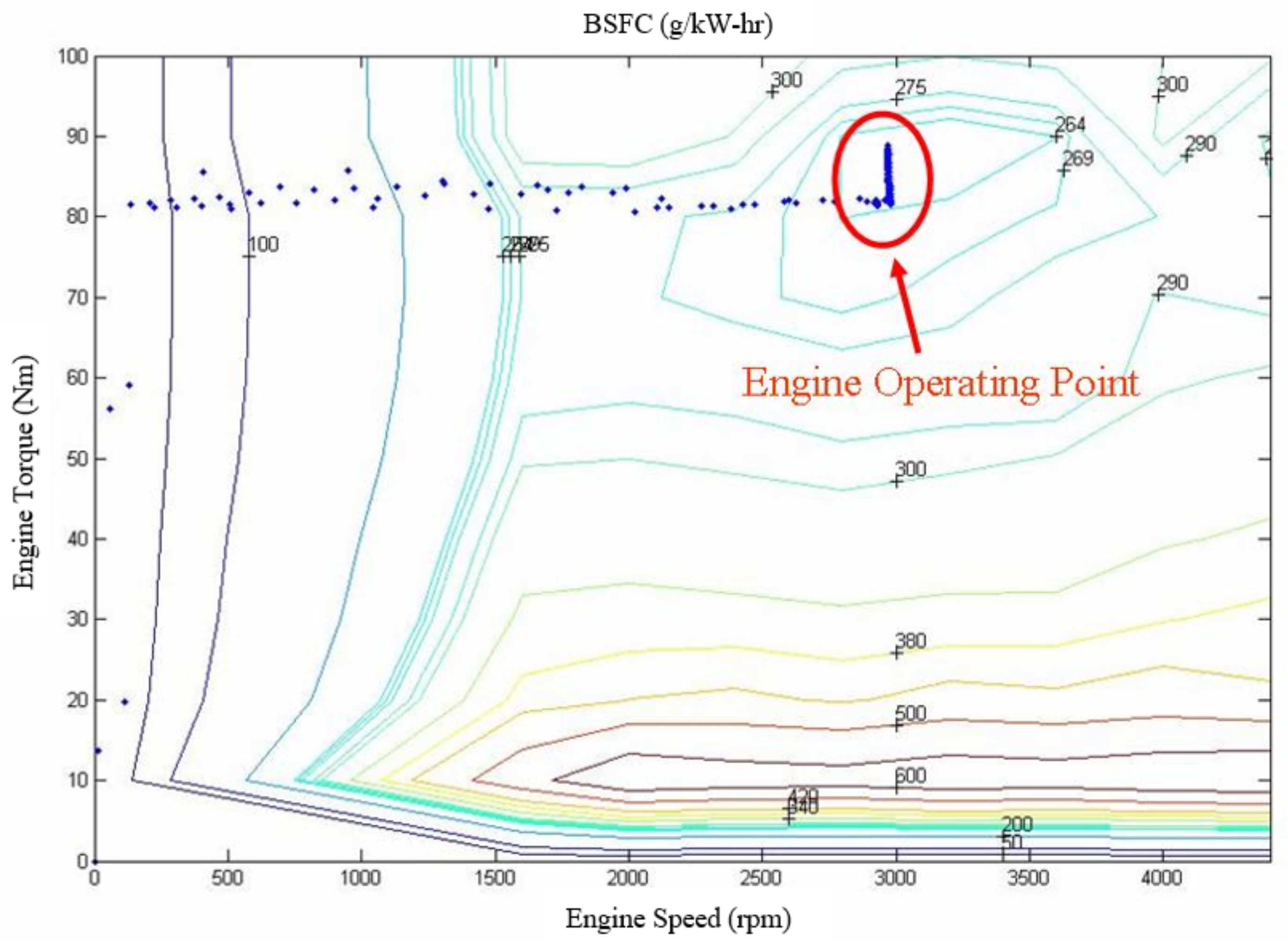
| Average BSFC | 275 (g/kW-hr) | 293.3 (g/kW-hr) | Decrease 6.24% |
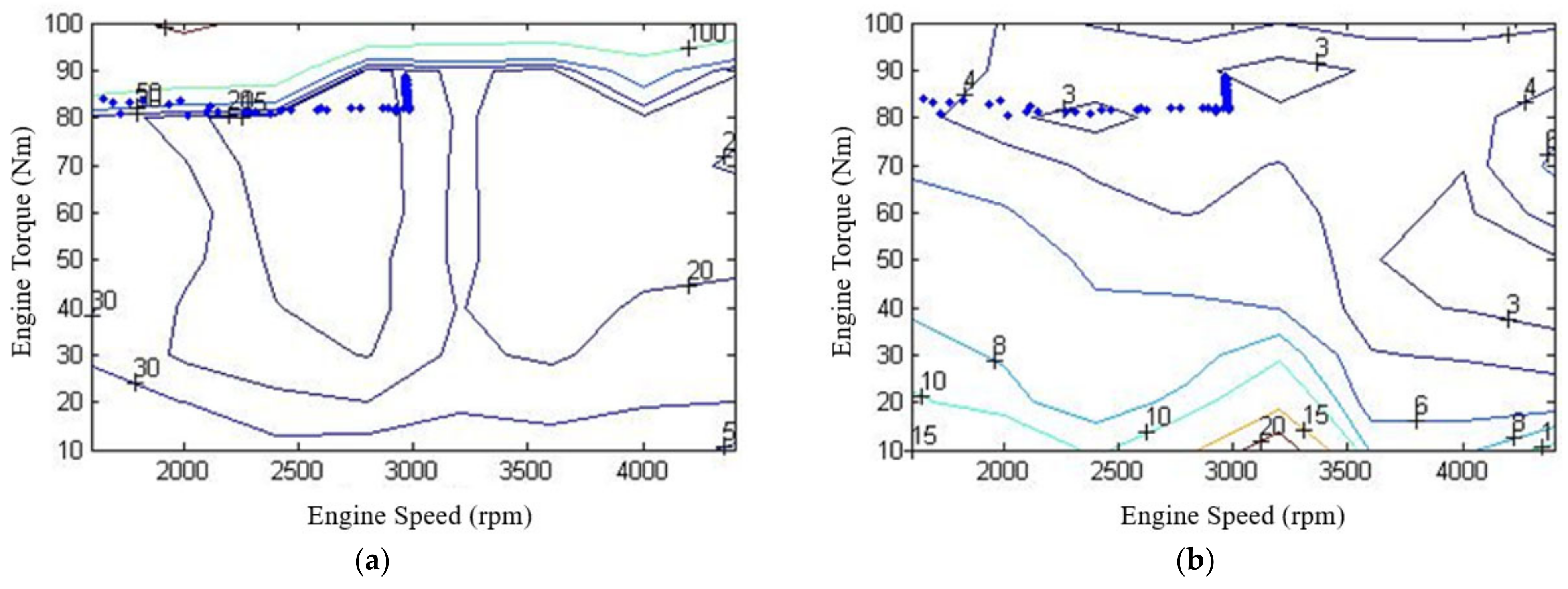
| Average BSCO | 18.24 (g/kW-hr) | 33.98 (g/kW-hr) | Decrease 46.32% |
| Average BSHCs | 3.1 (g/kW-hr) | 10.25 (g/kW-hr) | Decrease 69.76% |
Publisher’s Note: MDPI stays neutral with regard to jurisdictional claims in published maps and institutional affiliations. |
© 2022 by the authors. Licensee MDPI, Basel, Switzerland. This article is an open access article distributed under the terms and conditions of the Creative Commons Attribution (CC BY) license (https://creativecommons.org/licenses/by/4.0/).
Share and Cite
Huang, K.D.; Nguyen, M.-K.; Chen, P.-T. A Rule-Based Control Strategy of Driver Demand to Enhance Energy Efficiency of Hybrid Electric Vehicles. Appl. Sci. 2022, 12, 8507. https://doi.org/10.3390/app12178507
Huang KD, Nguyen M-K, Chen P-T. A Rule-Based Control Strategy of Driver Demand to Enhance Energy Efficiency of Hybrid Electric Vehicles. Applied Sciences. 2022; 12(17):8507. https://doi.org/10.3390/app12178507
Chicago/Turabian StyleHuang, Kuohsiu David, Minh-Khoa Nguyen, and Po-Tuan Chen. 2022. "A Rule-Based Control Strategy of Driver Demand to Enhance Energy Efficiency of Hybrid Electric Vehicles" Applied Sciences 12, no. 17: 8507. https://doi.org/10.3390/app12178507
APA StyleHuang, K. D., Nguyen, M.-K., & Chen, P.-T. (2022). A Rule-Based Control Strategy of Driver Demand to Enhance Energy Efficiency of Hybrid Electric Vehicles. Applied Sciences, 12(17), 8507. https://doi.org/10.3390/app12178507