Article

Aerodynamic Characteristics of Supersonic Rocket-Sled Involving Waverider Geometry

Key Laboratory of Aircraft Environment Control and Life Support, Ministry of Industry and Information Technology, Nanjing University of Aeronautics and Astronautics, Nanjing 210016, China
*
Author to whom correspondence should be addressed.
Appl. Sci. 2022, 12(15), 7861; https://doi.org/10.3390/app12157861
Submission received: 10 June 2022 / Revised: 6 July 2022 / Accepted: 7 July 2022 / Published: 5 August 2022
(This article belongs to the Special Issue Advances in Computational Fluid Dynamics: Methods and Applications)

Abstract

:
Rocket-sleds belong to a category of large-scale test platforms running on the ground which are mainly used for launching tests of weapon equipment and performance tests of airborne equipment. In the present study, a dynamic grid method was used to simulate the running process of an axisymmetric slender rocket-sled (ASRS) and a reversed waverider rocket-sled (RWRRS). The aerodynamic characteristics were studied and the ability of the waverider to control the shockwave with the ground effect was confirmed. In addition to reducing shockwave oscillation, the RWRRS was also able to increase lift and reduce drag. By means of power spectral density analysis, the characteristic frequencies of shockwave oscillations related to shock-wave/rail-fastener interaction were analyzed and a harmonic phenomenon was observed. Furthermore, the ability of the waverider rocket-sled to reduce pressure oscillation was confirmed by comparing the sound pressure level value.

1. Introduction

In recent years, the study of supersonic and hypersonic flows in the aerospace field has attracted the attention of numerous research institutions. Many countries have begun to focus on theoretical and experimental high-speed flow research, as reflected, for example, in the National Hypersonic Foundational Research Plan (NHFRP) [1]. The development of high-speed aircraft requires extensive tests to validate new theoretical ideas and technologies. However, conventional indoor tests, such as wind tunnel tests, are unable to accurately simulate the real working conditions of the tested device due to missing elements in dynamic performance data. In outdoor free-flight tests, it is difficult to guarantee the conditions of each test, and the test data obtained is quite limited. There is an urgent need for a large dynamic ground test device. The rocket-sled test system meets this need and is becoming more and more important in the field of high-speed testing worldwide.
The rocket-sled test system uses a rocket engine as the power unit which causes the rocket-sled test platform to slide along the high-precision track at high speed [2]. The rocket-sled test system has the advantages of both wind tunnel tests and free-flight tests. The carrying capacity, movement speed, acceleration and test environment are easy to control. In addition, the rocket-sled test system is not limited by the size and mass of the test, facilitating observation of the test process and collection of test data. Therefore, the rocket-sled test system has strong practical value and development potential, and can be applied to the aerodynamic testing of airborne equipment (e.g., ejection system, parachute, power system) and material research. The United States was the first country to build supersonic rocket-sled test equipment. It designed and built more than twenty tracks for rocket-sled tests, the most notable track being the Holloman High-Speed Test Track (HHSTT) [3]. The United States has carried out a number of experiments based on this track, and its researchers have put forward many rocket-sled system theories based on experimental data obtained.
The development of rocket-sled test systems in China occurred relatively late. In 1993, the first rocket-sled was built in Xiangyang, Hubei province. As a result of development of an expansion project for this high-precision rocket-sled, the length of the sled test system was extended to more than 6000 m—sufficient for further testing of a supersonic rocket-sled. In this paper, the supersonic rocket-sled model is based on this prototype, with a somewhat simplified shape.
In supersonic rocket-sled research, real tests are more reliable. Krupovage et al. [4] conducted several tests on three kinds of supersonic rocket-sleds and compared the results with data from wind-tunnel testing. They found that the aerodynamic force was a primary reason for tension changes. Rigali et al. [5] analyzed the pressure distribution on the surface of the sled body of a monorail supersonic rocket-sled and confirmed that ground testing of the rocket-sled could simulate the flight environment of low-altitude aircraft and obtain credible test results.
It has been unfortunate that the whole process of supersonic rocket-sled testing has taken so long. From the design of the test process to the preparation of the test device, the consumption of time and material resources has been quite high. In recent years, with the continuous development of computer technology, the computational fluid dynamics (CFD) method has been gradually developed and improved by researchers. It has been widely used in aerospace and other fields. The advantage of the CFD method is that it can collect rich flow information and obtain desired parameters very quickly. CFD can be used to coordinate and guide tests, effectively reducing the number of tests and thus significantly reducing costs. Slotnick et al. [6] have provided a very detailed and inspiring report on the future application of CFD in aerosciences. Many researchers have conducted numerical simulations for supersonic rocket-sleds [7,8,9,10].
In our previous work [11], numerical investigations of the supersonic axisymmetric base flow at Mach number 2.46 and Reynolds number 2.858 × 10 6 were carried out using a scale-adaptive simulation (SAS) approach. We found that there was no large-scale vortex shedding phenomenon, so vortex shedding was not the main factor causing vibration. In later studies, we identified some shockwave oscillation patterns of two common rocket-sleds through numerical simulation [12]. This work provides the basis for further investigation into supersonic rocket-sleds.
The Holloman test center found that the sled would resonate with the track at a certain speed. The results showed that the three resonance factors were shockwaves, vortex shedding and the excitation source of position, with shockwaves being the most important factor [13]. A large quantity of test data has shown that the vibration of the rocket-sled would be gradually intensified with increase in running speed. Several failed tests showed that such adverse vibration could threaten the safety of rocket-sled tests [13]. The existing rocket-sled consumes the vibration energy by adding damping devices such as springs. Turnbull et al. [14] proposed a soft structure connecting the rocket-sled and the rails to improve the vibration environment of the rocket-sled. This kind of damping device corresponds to passive damping and was found not to be sufficiently effective. In addition, the introduction of smoother rails and sliders was only able to reduce the vibration caused by random contact of sled rails and had little effect on aerodynamic vibration. Thus, a new approach to solving the problem of aerodynamic vibration of rocket-sleds is needed.
The aerodynamic vibration of a rocket-sled mainly comes from the conical shockwave and its reflected shockwave. If the generation of shockwaves is eliminated or suppressed, the vibration of the rocket-sled will be greatly reduced. Therefore, it is necessary to adopt some effective flow control methods. Flow control methods can be divided into active control methods and passive control methods [15,16,17,18,19,20]. Table 1 shows several common active and passive flow control methods. Because active flow control can be adjusted according to feedback, its control effect is better when the environment is changeable. However, the principle and structure of active control are often very complicated, which sometimes makes its application difficult. The ability of passive control to adapt to external changes is poor, but its application is relatively simple.
Shockwave control methods include changing geometric parameters, blowing suction flow and changing fluid properties. Among these, changing geometric parameters is a common method, which achieves its purpose by optimizing the shape or inclination angle [21]. If the formation and propagation direction of the shockwave can be controlled by changing the shape of the head and body of the rocket-sled, the intensity of the reflected shockwave can be weakened, and the influence of aerodynamic excitation vibration can also be reduced.
Waverider is a special shape designed to improve the lift-to-drag ratio of supersonic aircraft, which, in essence, is a form of aerodynamic shape optimization. Its leading edge generates attached shockwaves due to its special configuration and can block the flow of air above and below [41,42]. The hypersonic testing center in the University of Maryland conducted a great deal of experimental and theoretical research on the waverider, and developed the first waverider design and optimization software “MAXWARP”. This software can generate the corresponding waverider according to the design conditions [43]. Starkey et al. [44] proposed a simple analytical model for parametric design of a supersonic waverider, which can easily and quickly obtain the waverider under specific conditions and conduct performance optimization.
Most waverider studies have investigated supersonic intake and several have studied aircraft lift increase and drag decrease optimization. To the author’s knowledge, there has been no study considering control of the ground effects of waverider. Therefore, the main objective of this study was to investigate how to use waverider theory to control ground effects and reduce shockwave oscillation of a rocket-sled. As with other wave phenomena, a shockwave will reflect when it meets a solid wall. As the distance between an aircraft and the ground shrinks, the reflected shock may impinge again on the aircraft. When the distance is small enough, this phenomenon may happen more than once [45], causing significant pressure differentials. As shown in Figure 1a, additional disturbances occur when there are obstacles on the ground, as shown in Figure 1b shockwave oscillation in the flow field will cause the rocket-sled body to vibrate, which may reduce the service life of rocket-sled equipment. However, according to waverider theory, we know that its special configuration can control the shockwave effectively. The shockwave of waverider is attached to the leading edge, referred to as “attached shock”, as shown in Figure 1c. In this way, aerodynamic oscillation caused by head shock can be reduced, or even eliminated, directly at the source.
In this paper, a scale-adaptive simulation (SAS) method and dynamic grid method are used to simulate the conventional axisymmetric slender rocket-sled and the waverider rocket-sled. The shock generation and evolution pattern are analyzed. The waverider configuration is introduced in an innovative way into the rocket sled test platform. The ability of the waverider rocket-sled to control ground effects is illustrated by comparing the results of two configurations.

2. Simulation and Numerical Methodology

2.1. Governing Equations

Scale-adaptive simulation (SAS) is an improved unsteady Reynolds-averaged Navier–Stokes (URANS) formulation, which enables the resolution of a turbulent spectrum in unstable flow conditions. The SAS method essentially originated from the Reynolds-averaged Navier–Stokes (RANS) model. Thus, the governing equations of SAS are identical to that of RANS, i.e., Favre-averaged compressible Navier–Stokes equations. In the Cartesian coordinate system, the governing equations including mass, momentum and total energy equations can be described as:
ρ t + ρ u i x i = 0 ,
ρ u i t + ρ u i u j x j = p x i + τ i j + τ i j mod x j ,
( ρ E ) t + ( ρ E + p ) u i x i = q i q i m o d + u j τ i j + u j τ i j m o d x i .
Here, ρ , u i , p and E denote the density, velocity component, pressure and total energy, respectively. The viscous stress tensor τ i j and heat flux q i can be written as:
τ i j = 2 μ S i j 2 3 μ δ i j S k k ,
q i = μ P r ( γ 1 ) T x i .
Here, P r and T are laminar Prandtl number and static temperature, respectively. S i j = 0.5 ( u i / x j + u j / x i ) is the strain-rate tensor. Sutherland’s Law for the molecular viscosity coefficient μ is employed. γ is the specific heat ratio and δ i j denotes the Kronecker symbol. The total energy E can be given by the relationship:
E = p ρ ( γ 1 ) 1 2 u j u j .

2.2. The Scale Adaptive Simulation Model

According to the eddy viscosity hypothesis, τ i j m o d and q i m o d can be calculated by
τ i j m o d = μ T 2 S i j 2 3 δ i j S k k ,
q i mod = μ T ( γ 1 ) P r T T x i .
Here, μ T is the turbulent viscosity coefficient, which can be obtained by means of the turbulence model; P r T denotes the turbulent Prandtl number, which is often equal to 0.92 in the SAS or RANS computation. The SST-SAS model is based on the SST-RANS model by Menter [46]. The governing equations of the SST-SAS model differ from those of the SST-RANS model by the additional SAS source term Q S A S in the transport equations [47,48].
Q S A S = max ρ ζ 2 κ S 2 L L v K 2 C · 2 ρ k σ ϕ max | ω | 2 ω 2 , | k | 2 k 2 , 0 .
This SAS source term originates from a term in Rotta’s transport equation for the correlation-based length scale [49]. The model parameters in the SAS source term are ζ 2 = 3.51, σ ϕ = 2/3, C = 2; The value L in the SAS source term is the length scale of the modeled turbulence L = k / c μ 1 / 4 · ω . The von Karman length scale L v K is a three-dimensional generalization of the classic boundary layer definition.
L v K = max κ S / 2 u , C S κ ζ 2 / β / c μ α · Δ , Δ = Ω C V 1 / 3

2.3. The Dynamic Grid Method

The dynamic grid method is often used to simulate the displacement or shape change of the boundary of the computational domain. The problem of deformation is not considered in this study, so the rocket-sled can be regarded as a rigid body moving forward. The grid node distribution of the computing domain will change with variation in the boundary. To specify the range of grid deformations, it is necessary to determine the moving parts after rendering the computational domain mesh. If the computational domain has both a moving region and a stationary region, an intermediate interface is needed to connect the two parts.
The conservation equation of scalar ϕ in the control body when the position of the interface changes is:
d d t V ρ ϕ d V + V ρ ϕ u u g · d A = V Γ ϕ · d A + V S ϕ d V .
where t is the flow time, V ( t ) is the control volume whose shape and size vary with t, V is the moving boundary of the control volume, u g is the moving velocity of the grid, u is the velocity vector, Γ is the diffusion coefficient, and S ϕ represents the source term of the scalar ϕ . The backward differential term of the time derivative is:
d d t V ρ ϕ d V = ( ρ ϕ V ) n + 1 ( ρ ϕ V ) n Δ t .
Superscripts n and n + 1 indicate the current and next time steps, respectively. The control volume V n + 1 can be obtained by the following formula:
V n + 1 = V n + d V d t Δ t .
To satisfy the conservation law of the grid, it is also necessary to satisfy:
d V d t = V u g · d A = j n f u g , j · A j .
In the formula, n f is the quantity of surfaces around the control volume, and A j is the area vector in the j side. The u g , j · A j of each surface on the control volume can be calculated from the following formula:
u g , j · A j = δ V j Δ t .
Here, δ V j is the area that the j surface on the control body sweeps in time step Δ t .

3. Results and Discussion

3.1. Validation and Computational Reviews

To verify the correctness of the chosen calculation method, we repeated the supersonic test results of [50] for an axisymmetric slender body by the above numerical method. The governing Equations (1)–(3) are integrated numerically based on the finite volume method solver. The second-order upwind difference scheme is used to discretize the convection term in the model. The Roe-FDS flux scheme is used to reduce the dissipation in the computation, which further improves the accuracy of supersonic simulation. According to experiments performed concerning supersonic axisymmetric flow [50], the free-stream Mach number M and Reynolds number Re based on the cylinder diameter (d = 37 feet) are chosen as 2.5 and 4.2 × 10 6 , respectively. We output the pressure coefficient at sections 3.5 d and 5.5 d from the nose. The pressure coefficient C P can be defined as:
C P = p p 0.5 ρ U 2 .
Figure 2 shows the calculation results and experimental results [50], in the form of plots of C P versus θ (the angle between the radial direction and vertical direction), for the isolated body at two longitudinal locations. The pressure coefficients of the two sections are close to the experimental values. These results show that the chosen numerical method can be used to simulate the supersonic flow of a similar slender body.
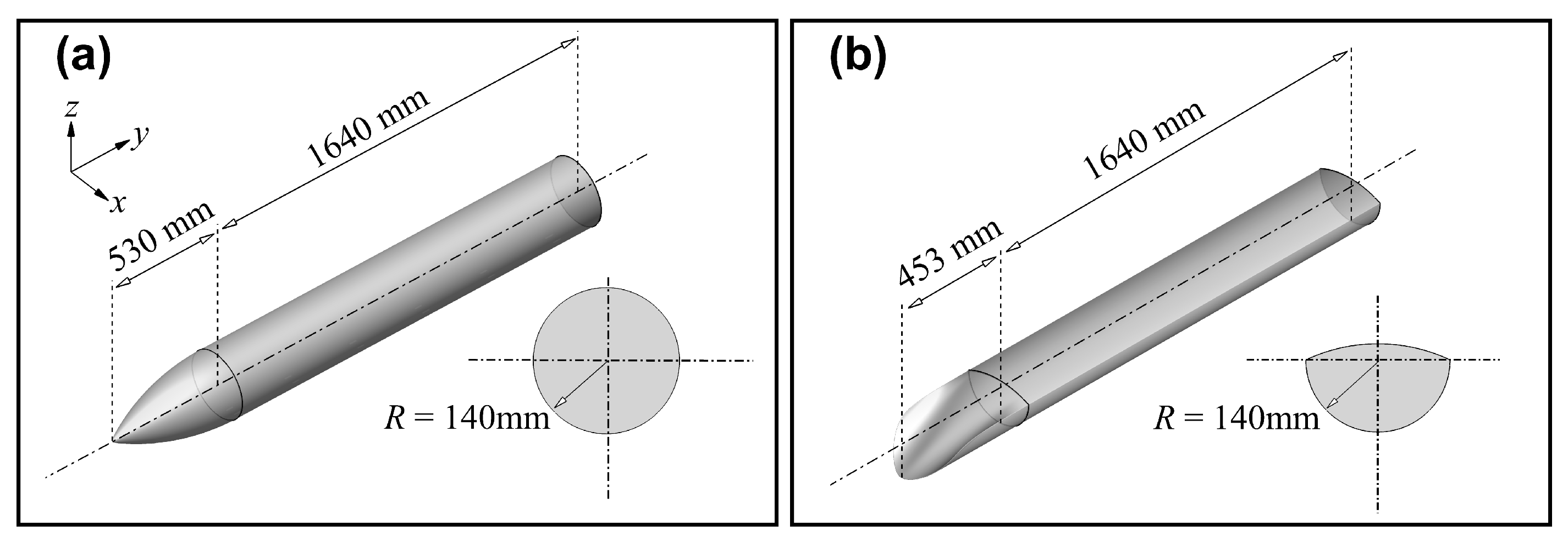
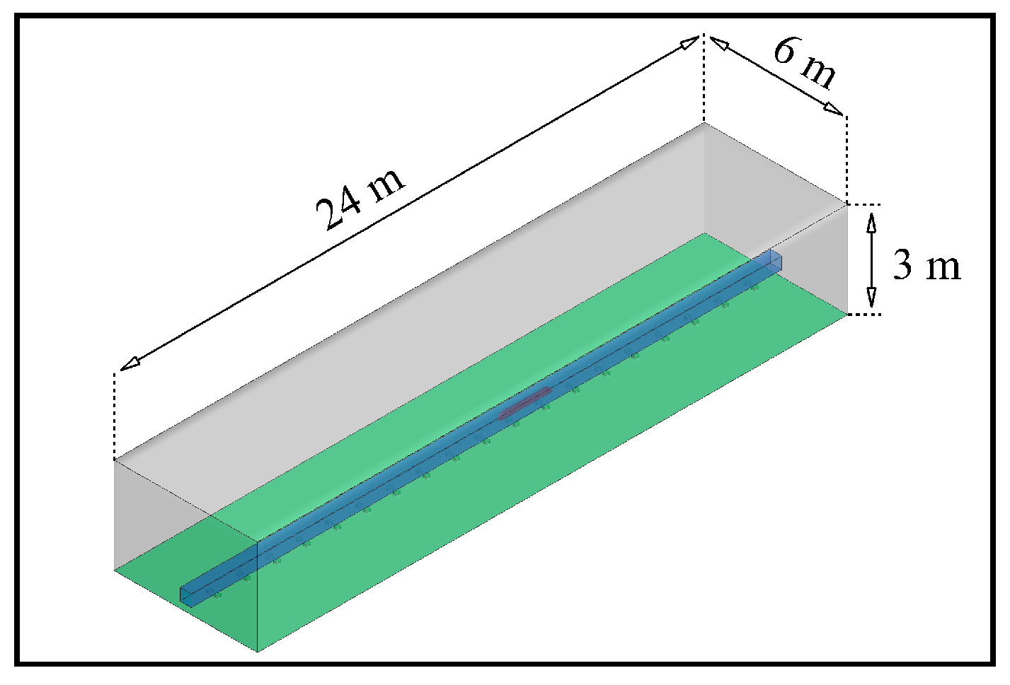
The axisymmetric slender shape is the most common configuration in existing rocket-sled test systems. Figure 3a shows the shape parameters of the axisymmetric slender rocket-sled (ASRS). For comparison, Figure 3b shows the reversed waverider rocket-sled (RWRRS) integrated configuration based on waverider theory [51]. The design of the waverider is carried out using the following methods: numerical simulation of conical flow field, upper surface design, obtaining leading edge parameters, streamline tracing and lower surface design. After obtaining the shape parameters of the waverider, an integrated design of the RWRRS is obtained by combining the lower surface of the body with a smooth transition connection. To make sure the contrast is reasonable, both structures have the same radius R in the lower half. To ensure the stability of the rocket-sled movement, it is necessary to set the computational domain to be sufficiently long. Therefore, we set the length of the computational domain to above 24 m, as shown in Figure 4. The rocket-sled is evaluated using a ground test system, so the operating environment can be determined according to commonly used atmospheric environmental parameters. The local Mach number of the rocket-sled M r is chosen as 2.0, and the ambient pressure p is 101.325 kPa.
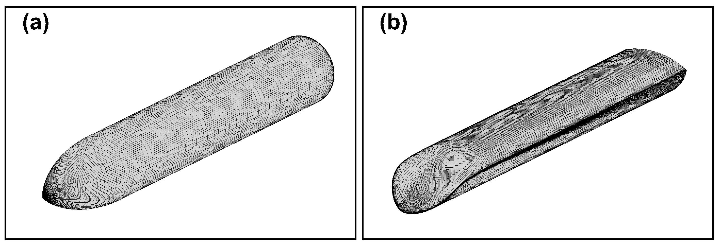
With respect to computing parameters, a no-slip wall condition is used in the ground and rocket-sleds. The far-field condition is adopted at the rest of the boundaries to avoid the influence of the boundary on the calculation results. The no-slip wall condition is described as Equation (17) and the far-field condition is described as Equation (18). As shown in Figure 5, we use a structured grid to discretize the computational domains. The nearest grid height normal to the wall is equal to 2 × 10 5 m and the total quantity of grid elements is about 8 million. The computational time step is 3 × 10 6 s, which is small enough to obtain the unsteady phenomena of the rocket-sled flow field.
u = v = w = 0 .
ρ = ρ , p = p , u = 0 , v = 0 , w = 0 .

3.2. The Flow Field Characteristics

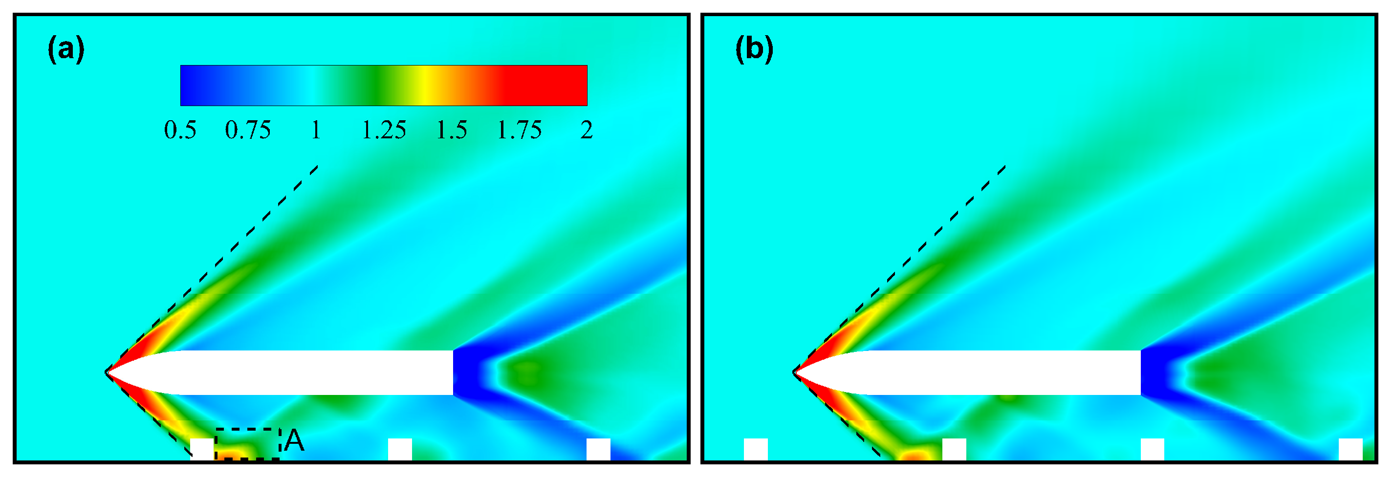
As the shockwave passed over the ground and the fasteners, the pressure on the fastener and the ground increased rapidly. We non-dimensionalized the pressure as p* = p/ p . Since p equals a standard atmosphere pressure, the value of p* represents the corresponding atmospheric pressure. According to Figure 6, there are some similarities in the pressure distribution above the nose of two rocket-sleds. On the left side of the dotted line, which is unaffected by the shockwave, the pressure is always 1 atm, while on the right side of the shockwave, the pressure rises above 2 atm. The bow shock formed from the nose component collides with the ground and generates a reflected shockwave, then the reflected shockwave collides with the lower surface of the rocket-sled and further generates a complex reflected shock system. The shock and reflected shock structures below the rocket-sled are very similar to what is predicted in Figure 1, which is also consistent with the research of Doig [52]. There are also some similarities in the wake flow field of the two rocket-sleds configurations. The forward motion of the rocket-sleds results in a local “vacuum” behind the body, which makes the air pressure drop below 0.5 atm. The flow of air through the tail of rocket-sleds is similar to Prandtl–Meyer flow, which produces a series of expansion waves [53].
In addition to the above similarities, there are several notable differences in the flow field between the two configurations, the most obvious of which is the flow field under the front part. Because of the shape of the bluff body, the shockwave propagates around the ASRS in every direction, and the flow field below is directly affected by the shockwave. A significant increase in pressure can be found in the A region of Figure 6a, where the shockwave is reflected. What is different is that the flow field under the RWRRS is less disturbed due to the special configuration. As shown in Figure 7a, the pressure distribution below the RWRRS is almost uniform, just showing a little pressure leakage in area A due to the existence of leading edge chamfer.
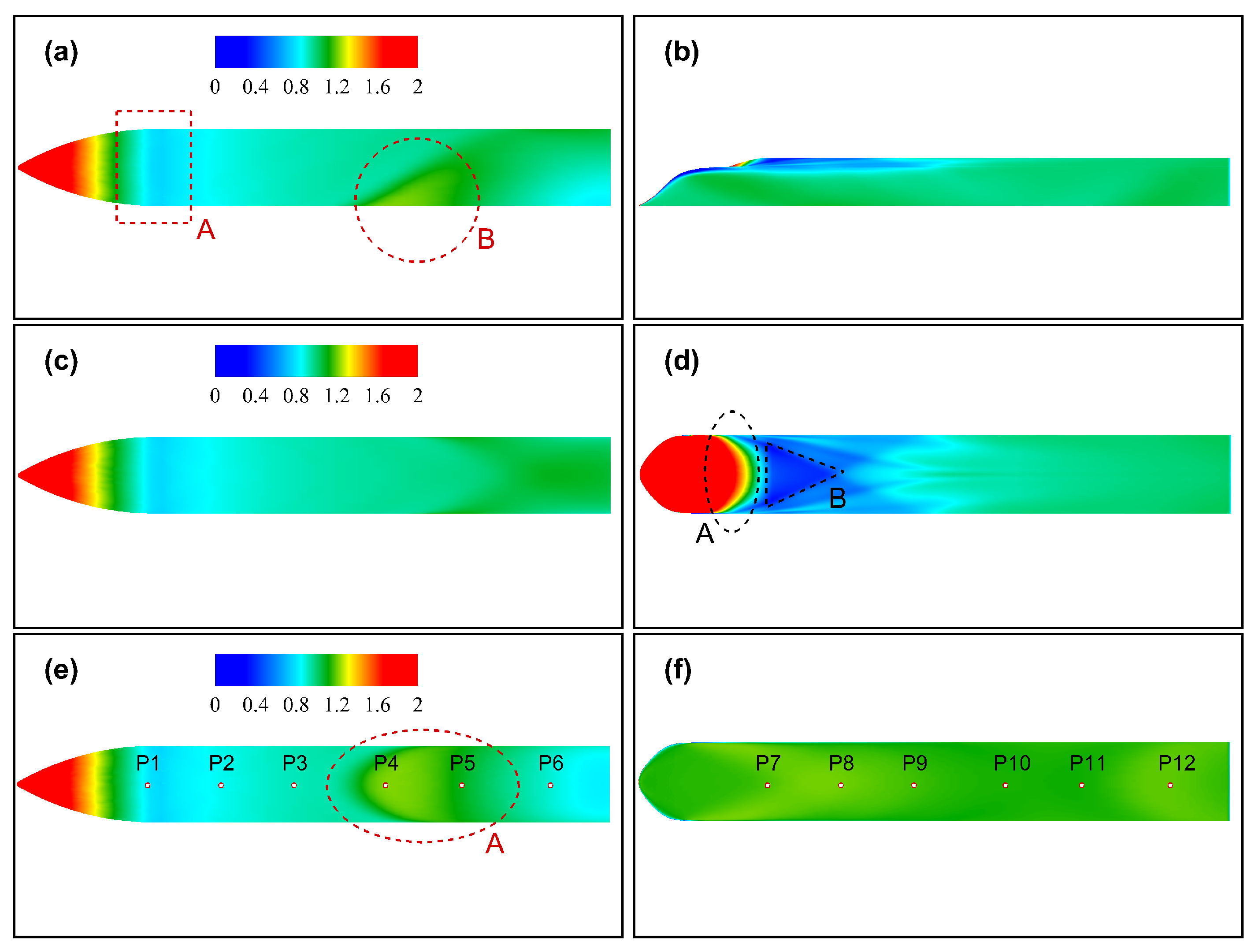
In addition to the difference in the flow field pressure distribution, the surface pressure distribution of the two kinds of rocket-sleds also show great differences. According to Figure 8a, the pressure distribution on the head surface of the ASRS changes more regularly like a “ring”, with pressure gradually decreasing backwards. It is worth noting that in area A of Figure 8a, the pressure of this part drops below 0.7 atm. This phenomenon is very common in such flow problems around the bluff body [54]. This process is similar to supersonic air blowing—the supersonic flow gradually expands and accelerates as it passes over a continuous convex surface, resulting in a minimum of pressure as it enters the flat section [54]. In area B in Figure 8a, as well as area A in Figure 8e, the pressure rises to a local maximum value, which intuitively conveys the impact of shockwave reflection. However, the pressure distribution on the surface of the RWRRS is quite different. Firstly, if the area near the head of the rocket-sled, as shown in area A in Figure 8d, is observed, the area with high pressure is almost concentrated in the front part. Then the pressure descends backwards due to the expansion of the air flow on the convex surface. However, because the shape changes more rapidly than ASRS, the pressure drop is more dramatic. The pressure contours of the area A in Figure 8d are similar to several “crescent” shapes due to the change in pressure. Then there is a large area of low pressure in the right of area B in Figure 8b; the lowest pressure drops below 0.5 atm, and this area looks like a “triangle”. There may be two reasons for this special phenomenon: one is the reason mentioned above (the expansion of air flow), the other is that there are raised shapes on both sides of the waverider configuration, which will hinder the flow of air. This special shape causes the air flow to be compressed in the middle and to expand backward. Such a special flow pattern leads to the formation of a triangular low-pressure area. It is of note that the most important phenomenon occurs in Figure 8f, where the pressure on the lower surface is almost homogeneously distributed. This pressure distribution indicates that there is almost no shockwave oscillation on the lower surface of the RWRRS. Therefore, no pressure fluctuation can be observed. This is the most intuitive representation of the waverider configuration controlling shock oscillations.
In general, the friction of the bluff body comes from the attached flow before the boundary layer separation, while the friction behind the separation point is relatively small. The distribution of friction can be obtained by analyzing the surface friction coefficient C f , which is defined as follows:
C f = 2 τ w ρ U 2 S r e f
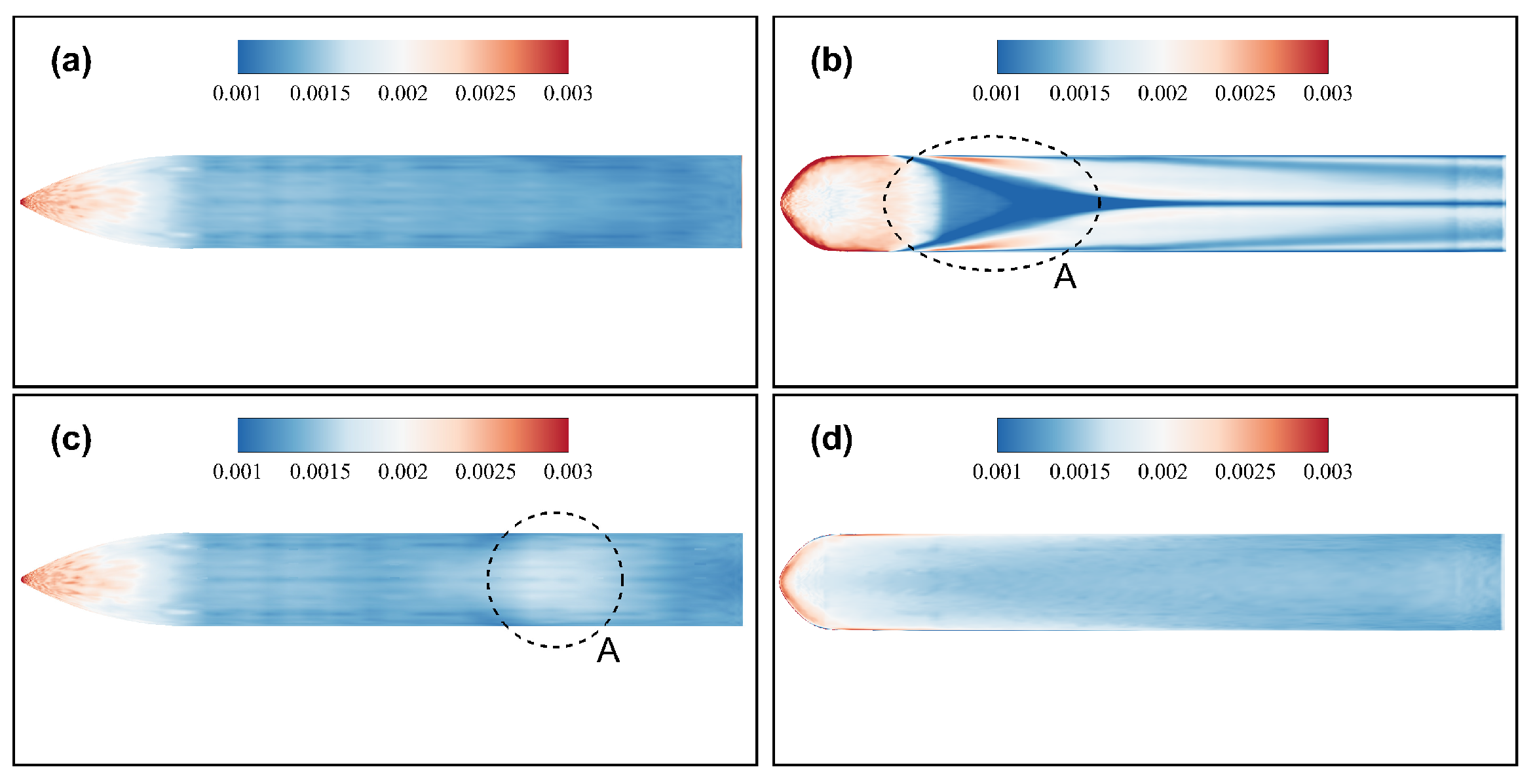
where τ w is the frictional stress on the wall, ρ and U are the free-stream density and velocity, respectively. S r e f is the reference area; the projected area in the vertical direction is taken in this paper. Figure 9 shows the C f distribution of the two configurations. It can be seen that the distribution on the upper and lower surfaces of ASRS is almost identical, except for a small increase in the A region of Figure 9c. This phenomenon indicates that the C f value will be affected when the reflected shockwave collides on the wall [55]. The distribution of RWRRS is quite different due to its special configuration. Near the leading edge line, the C f value is very large, which is caused by the properties of the waverider. The leading edge of the waverider is extremely sharp and will split the air above and below. In region A of Figure 9b, a more prominent triangular region is observed which is seen in Figure 8d. However, the C f distribution under RWRRS is more uniform, which is different from the upper side. These results reveal the ability of the waverider to split flow above and below, which can also be applied to control flow through ground effects.
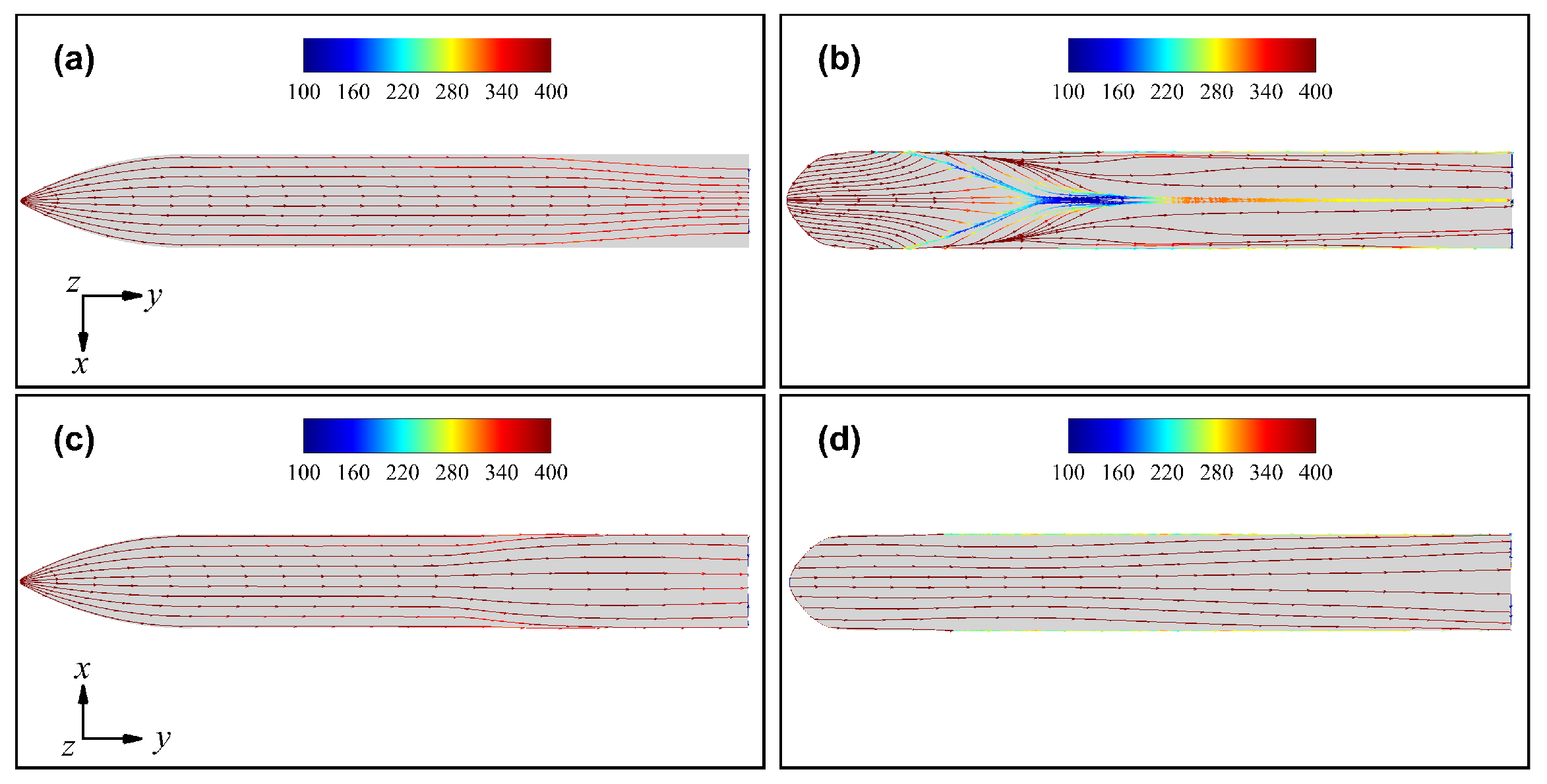
Limiting streamlines are often used to describe flow trends near a wall and to identify the location of flow separation [56,57,58]. Figure 10 compares the surface limiting streamlines on two rocket-sleds. It is observed that the air flow at the bottom of the ASRS flows outward due to the influence of reflected shockwaves, as shown in Figure 10c. However, the limiting streamlines on RWRRS are different. The limiting streamlines do not bypass the sides, but continue to flow streamwise, which suggests that the flow below RWRRS is less disturbed.
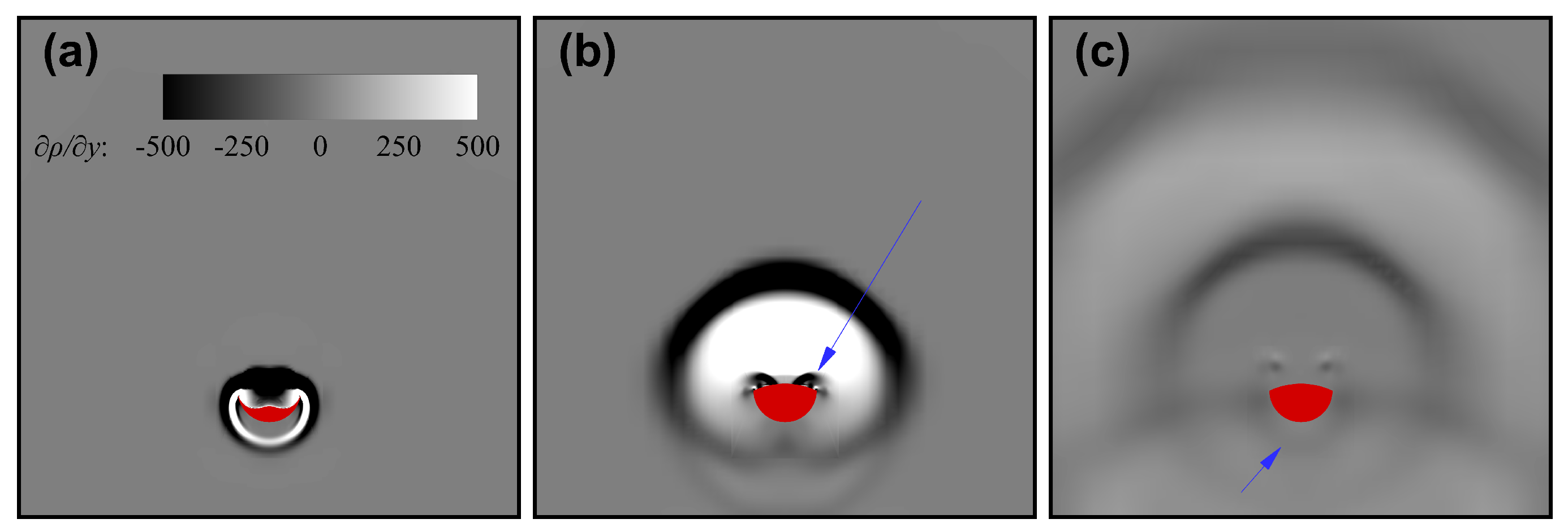
To observe the shockwave evolution process in the flow field more directly, we output the partial derivative of the density of air along the direction of the coming flow, namely ρ / y . In Figure 11a, we see that, in the initial stage of shockwave formation, the cross section of the shockwave looks like an annulus. Since the shockwave had not moved to the ground at this time, it can develop freely in all directions. Therefore, the shockwave has a high axisymmetry distribution and is also known as “bow” shockwave or conical shock [55,59]. Subsequently, the shockwave moves to the ground and reflects after colliding with the ground, as shown in Figure 11b. Finally, the reflected shockwave spreads upward and collides with the lower surface of the sled. The structure and evolution of shockwaves are similar to many experimental and numerical simulation results [13,45,52,54]. This collision creates large pressure fluctuations on the rocket-sled. However, unlike conventional ground effect problems, the fasteners are equidistant on the ground, so a battery of shockwave collisions will generate periodic pressure excitation on the body of the rocket-sled. This periodic phenomenon is analyzed further in the following Section 3.3 and Section 3.4.
As shown in Figure 12a, in the initial stage, the shockwave structure near the head of the RWRRS is quite different from those in Figure 11a. Upward-propagating shockwaves are also roughly circular, as with ASRS, but downward propagating shockwaves are hardly observed. As shown in Figure 12b,c, the downward compression wave is very weak, and the strength weakens further after it collides with the ground. The compression wave that eventually returns to the surface below is difficult to distinguish. This phenomenon also shows that the RWRRS has a good effect on shockwave control and can eliminate most detached shockwaves in the flow field below.

3.3. Force Characteristics

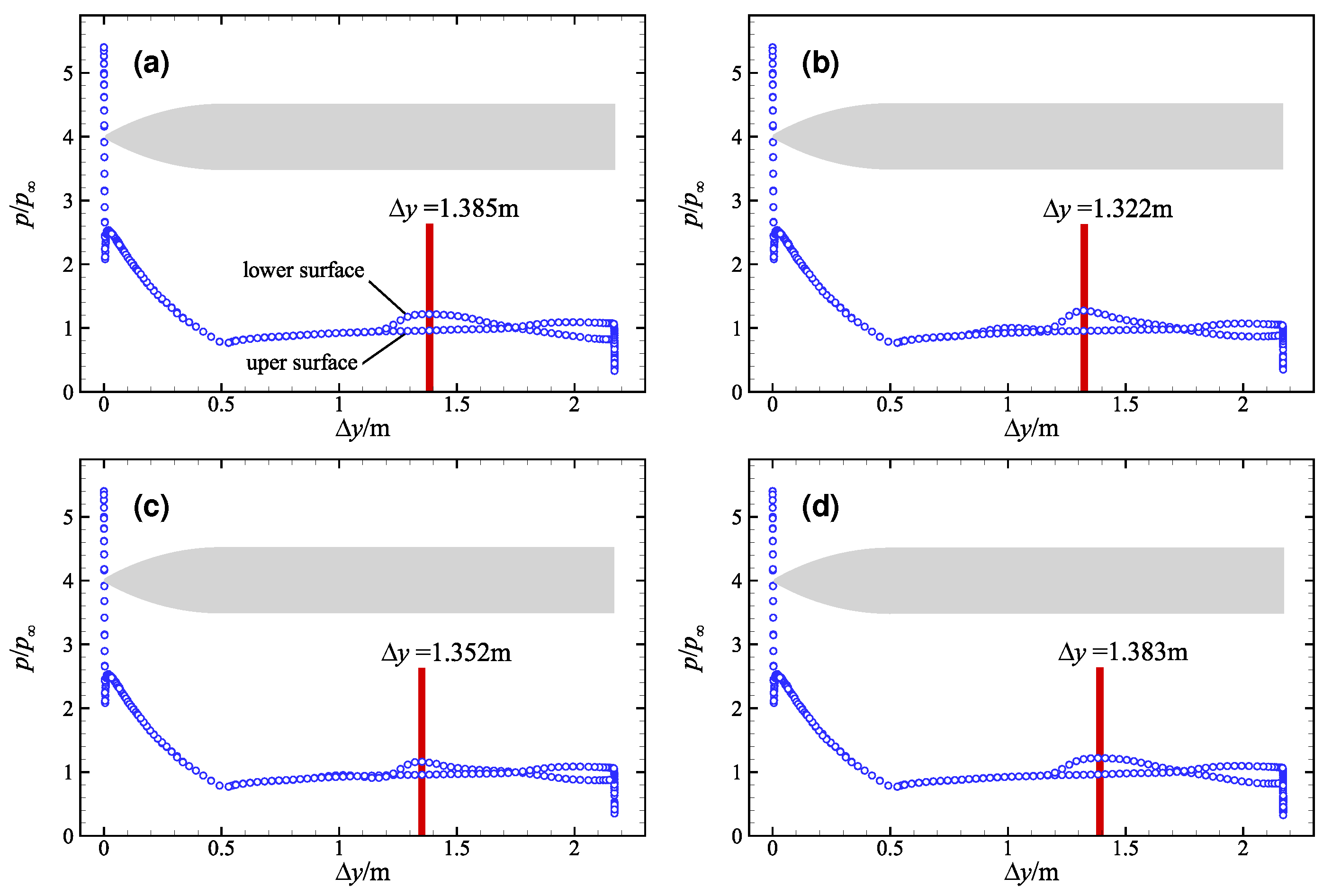
Shockwave oscillation has a strong unsteady property, so it is necessary to investigate the time domain characteristics of shockwave oscillation. Figure 13 shows the pressure distributions of the ASRS at the symmetrical interface at four different moments. To compare the position on the rocket-sled, we take the origin of the nose of the rocket-sled as Δ y = 0. In the front part of the rocket-sled, the pressure distribution on the upper and lower surfaces is almost identical, which indicates that the front part of the rocket-sled is not affected by head shockwaves and reflected shockwaves. Furthermore, the pressure distributions at four different moments are also identical; this implies that the shockwave structure at the front of the ASRS is quasi-steady in both time and space domains.
However, there are discrepancies in the middle and rear of the ASRS. In Figure 13a, we find that, at t 1 = 0.0180 s, the pressure on the lower surface reaches a local maximum value at Δ y = 1.385 m, which is the central position of the reflected shockwave action at this time. Then in Figure 13b, the local maximum pressure point is located at Δ y = 1.322 m. Compared with Figure 13a, the local maximum pressure point (LMPP) shifts forward. However, at t 3 = 0.0192 s, not only does the position of the LMPP change, but the pressure distribution in its vicinity is also very different. In the space domain, the pressure changes more dramatically; thus, pressure increases rapidly from about 1 atm to LMPP and then rapidly recovers to about 1 atm. Similar to the common ground effect problem, the pressure distribution on the rocket-sled surface should be almost constant over time if there are no additional disturbances on the ground. Therefore, the change in the LMPP can be inferred to be caused by the fastener. By comparing Figure 13a–d, we can make a reasonable inference that the time interval of the relative maximum pressure point changes in the four moments may be related to the shockwave oscillation frequency caused by the fastener.
The pressure distribution for the RWRRS is quite different from that of the ASRS. As shown in Figure 14a–d, the upper and lower surfaces of RWRRS are separated by leading edge lines. The pressure increases to more than 5 atm above the leading edge and then begins to fall back. In the region between Δ y = 0.5 m and Δ y = 0.65 m, the pressure drops to the lowest value of about 0.4 atm, which is consistent with the triangular region shown in Figure 8. The pressure then recovers to 1 atm in the region after Δ y = 1 m. The pressure on the lower surface is always around 1atm with very little fluctuation, which indicates that there is little aerodynamic interference to the lower surface. More importantly, by comparing Figure 14a–d, there is hardly any change observed in the pressure distribution at different times. The ability of RWRRS to reduce shock oscillations is thus demonstrated.
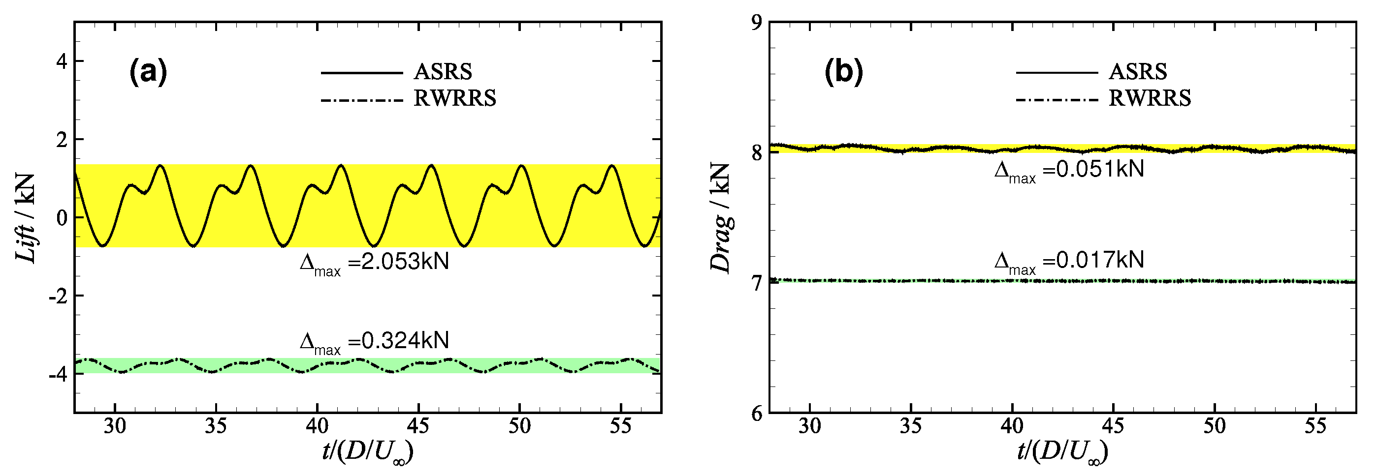
The properties of lift and drag are important results in many aircraft studies as they reflect the aerodynamic performance of a certain configuration. As shown in Figure 15, we extracted the lift and drag vibration curves of two rocket-sleds for comparative analysis. Δ m a x represents the difference between the maximum value and the minimum value. The average lift of the ASRS is 0.361 kN, which means the ASRS has an upward trend in vertical direction. The instantaneous lift varies greatly from −0.734 kN to 1.319 kN and the fluctuation range is over 2.063 kN. It can be inferred that the dramatic change in lift will cause the sled to oscillate vertically. This vertical oscillation will lead the sled to “jump” on the rails, which would increase the wear and tear of the track and make the operational environment worse. The precision of the rail is very high, and such a large vibration can greatly damage the accuracy of the rocket-sled test system. It is satisfying that the RWRRS can reduce the lift fluctuation range from Δ m a x = 2.063 kN to Δ m a x = 0.324 kN, which is approximately 84%. This would significantly reduce the jumping phenomenon of the rocket-sled. The average lift is about −3.777 kN, which means the sled will be pressed firmly on the rails. The smooth operation process also ensures the accuracy of the test. In Figure 15b, both the mean drag and the amplitude of fluctuation of the RWRRS are smaller compared with the ASRS. The mean drag decreased by 12.5% and the amplitude of fluctuation decreased by 66.7%. The smoother drag curve would allow the sled to move at a more constant acceleration. In general, the RWRRS can increase lift and decrease drag. Furthermore, it can also reduce the amplitude of lift and drag fluctuation, which helps the rocket-sled test system to run more stably and smoothly.

3.4. Spectral Analysis and Acoustic Characteristics

According to the above analysis, the shockwave oscillation under the rocket-sled is periodic. The most direct way to investigate this phenomenon is to analyze the time characteristics of pressure. Before we performed the calculation, several monitoring probes were arranged below two rocket-sleds, as shown in Figure 8e,f. The pressure change curve of each monitoring probe with time has been extracted in Figure 16. To make the results more reliable, the data for the initial running period is omitted and only the data for the stable running period is retained. The dominant frequency of the shockwave oscillations is determined by plotting the spectra of the pressure signals. The spectra are computed using the fast Fourier transform (FFT) and power spectral density (PSD) of the signals [60]. To conduct power spectrum analysis more conveniently, the pressure and time are normalized to conduct power spectrum analysis by:
p * = p / p ,
t * = t D / U .
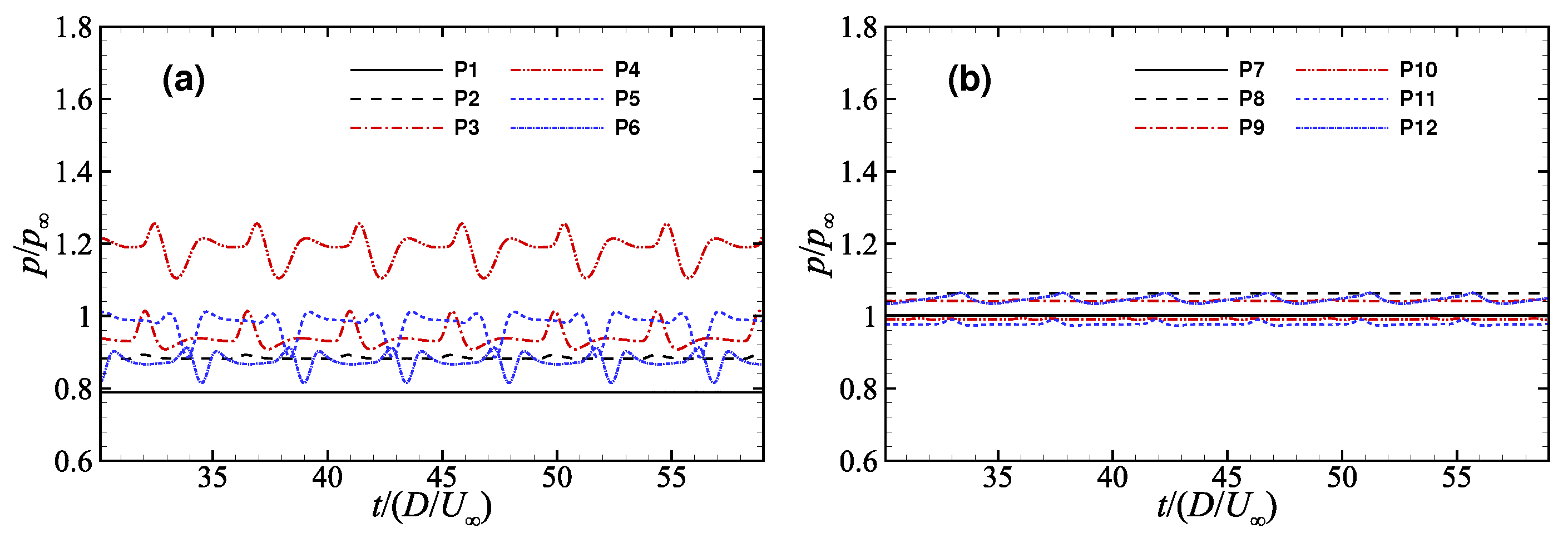
According to Figure 16a, the pressure value of P1 is always about 0.78 atm, which is consistent with the conclusion above that “the front part of the rocket-sled is not affected by head shockwaves and reflected shockwaves”. If the probes were set below the middle of the ASRS, they could detect more pronounced periodic pressure fluctuations, such as probes P3 and P4. The mean pressure and fluctuation range of probes P3 and P4 are both larger than the other probes, which indicates that this region is directly affected by the reflected shockwave. There are some reductions in the mean pressure and fluctuation range at the rear of the rocket-sled. These results suggest that, in a rocket-sled launch test, more pressure detectors should be arranged below the middle part of the ASRS if we want to obtain more experimental data about shockwave oscillation. As shown in Figure 16b, it is satisfactory that all the pressure probes of the RWRRS show very small pressure fluctuations, and that the mean pressure of all probes are concentrated within 0.96 atm to 1.16 atm. These results show that, during operation of the RWRRS, the pressure excitation on the sled body is minimal, and that this characteristic hardly changes with time.
To investigate the unsteady characteristics related to shockwave oscillation, the PSD profiles for pressure signals are analyzed in Figure 17a,b. In spectral analysis, a dimensionless criterion number, the “Strouhal number”, is often used to characterize unsteadiness. Assuming the frequency of fluid fluctuation or oscillation is f, then the Strouhal number can be defined as:
S t = f D U .
Although the mean pressure and fluctuation range of the probes on the two configurations are quite different, their characteristics of oscillation are almost identical. Several peaks can be observed in the PSD profiles, corresponding to the characteristic frequency S t 1 0.212. These are associated with the interaction between the shockwave and the railway fasteners. In addition, there is another peak at S t 2 0.448. The relationship “ S t 2 2 S t 1 ” indicates that the shockwave oscillation in the rocket-sled flow field has a harmonic phenomenon. This harmonic phenomenon has been observed in many experimental studies [13].
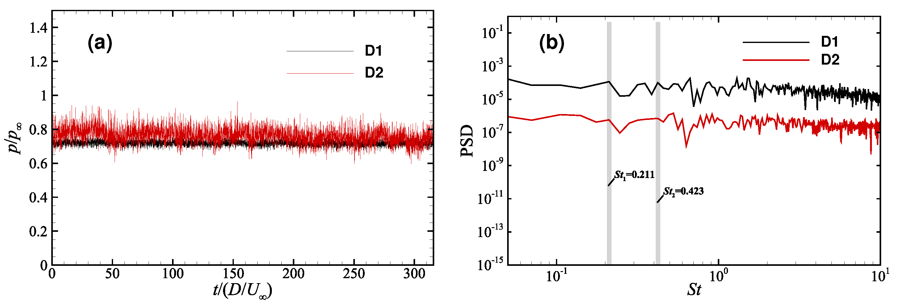
To compare and verify the correctness of our calculations, we extracted some data from a real launch test at Xiangyang. Then we post-processed the pressure signal of detectors D1 and D2 in the same way as for the numerical calculations. Figure 18a,b show the pressure curves and the PSD analysis results during the stable operating stage. A peak can be observed in the PSD profile, as shown in Figure 17, corresponding to the characteristic frequency S t 1 0.211. In addition, we also found another peak where S t 2 0.423. This implies that a harmonic phenomenon was evident in the experimental data, similar to the computational results obtained by Lamb [13]. This harmonic phenomenon may have contributed to the damage to the rails.
Sound pressure is the physical quantity used most commonly in sound measurement [60,61]. The sound pressure level is usually used to describe the intensity of sound pressure. By employing the concept of sound pressure level (SPL), it is easy to describe linear variation in sound pressure.
Most often, we use the root mean square (RMS) of dynamic sound pressure to calculate the SPL as follows:
p a v g = 1 t 2 t 1 t 1 t 2 p ( t ) d t ,
p R M S = R M S ( p ( t ) p a v g ) ,
S P L ( dB ) = 20 · log 10 p R M S p r e f ,
where p r e f represents the minimum audible sound pressure amplitude of 20 μ Pa at 1000 Hz. The human auditory system approximates a logarithmic scale, hence the introduction of sound pressure defined in dB form.
By means of Equations (23)–(25), we processed the data of probes P2–P5 and P8–P11 on two rocket-sleds, as shown in Figure 19. By comparing the results for P2 to P5, we found that the SPL value of the front probes was smaller than for the other probes because of less shockwave oscillation. The SPL values of the probes in the middle part reached 150 dB and some of them were close to 160 dB. Such a large SPL value means that the test devices were excited by extremely high sound waves when the rocket-sleds passed by. This would cause additional impact on nearby ground devices and also prevents the maximum operating Mach number of the sled from rising further. It is reassuring that the results obtained for the RWRRS are satisfactory. According to the blue bar graph in Figure 19, the RWRRS can reduce the sound pressure level by 30∼35 dB, which greatly reduces the impact on the surrounding equipment and rocket-sled itself.

4. Conclusions

Supersonic rocket-sleds travelling at Mach number 2.0 were investigated using scale-adaptive simulation and a dynamic grid algorithm approach. Two configurations were considered, including an axisymmetric slender rocket-sled (ASRS) and a reversed waverider rocket-sled (RWRRS). During the operation of ASRS, the “bow” shockwave generated on the nose and then collided with the ground and fasteners. The fasteners were equidistant on the ground; hence, the series of shock collisions produced periodic reflected shockwaves, generating periodic excitation of the rocket sleds. The excitation caused by the shockwaves caused adverse vibration of the ASRS, which may affect its stability and safety. To solve the problem of reflected shock excitation, we introduced a waverider modification method as a shock control strategy and obtained the RWRRS. Compared with the results of the ASRS, the shockwave evolution process and flow characteristics of the RWRRS changed greatly. The flow field under the RWRRS was not disturbed greatly. Furthermore, RWRRS was able to reduce fluctuation in lift and drag, while increasing lift and reducing drag, confirming that RWRRS had a strong ability to control shockwaves. After PSD analysis of the surface pressure probes of two kinds of rocket-sleds, we found that the S t numbers of shockwave oscillation on the two rocket-sleds were consistent. Finally, we confirmed the effectiveness of RWRRS in reducing acoustic oscillations through SPL comparative analysis.

Author Contributions

Conceptualization, C.X.; methodology, B.W.; validation, Y.Y.; investigation, Y.Y.; writing—original draft preparation, Y.Y.; writing—review and editing, J.S.; supervision, J.S. All authors have read and agreed to the published version of the manuscript.

Funding

This research was supported by the National Natural Science Foundation of China (Grant No. 12172172), the Aeronautical Science Foundation of China (Grant No. 20200029052001) and the Priority Academic Program Development of Jiangsu Higher Education Institutions.

Institutional Review Board Statement

Not applicable.

Informed Consent Statement

Not applicable.

Data Availability Statement

Not applicable.

Conflicts of Interest

The authors declare no conflict of interest.

References

  1. Schmisseur, J.D. Hypersonics into the 21st century: A perspective on AFOSR-sponsored research in aerothermodynamics. Prog. Aerosp. Sci. 2013, 72, 3–16. [Google Scholar] [CrossRef]
  2. Szmerekovsky, A.G.; Palazotto, A.N. Structural dynamic considerations for a hydrocode analysis of hypervelocity test sled impacts. AIAA J. 2006, 44, 1350–1359. [Google Scholar] [CrossRef]
  3. Ayers, G.H.; Hooser, M.D.; Black, D.E.; Leader, A.M. Exploration of dynamic rocket sled modeling parameters at Holloman High Speed Test Track. AIAA Paper 2009-1707 2009. [Google Scholar] [CrossRef]
  4. Krupovage, D.J.; Mixon, L.C.; Pokorny, O.T. Wind-tunnel and full-scale forces on rocket sleds. J. Spacecr. Rockets. 1967, 4, 1346–1351. [Google Scholar] [CrossRef]
  5. Rigali, D.J.; Reltz, L.V. High speed monorail rocket sleds for aerodynamic testing at high Reynolds numbers. J. Spacecr. Rockets. 1968, 5, 1341–1346. [Google Scholar] [CrossRef]
  6. Slotnick, J.; Khodadoust, A.; Alonso, J.; Darmofal, D.; Gropp, D.; Lurie, E.; Mavriplis, D. CFD Vision 2030 Study: A Path to Revolutionary Computational Aerosciences; NASA/CR-218178; NASA Langley Research Center: Hampton, VA, USA, 2014. [Google Scholar]
  7. Lumb, S.B.; Bosmajian, N. Non-vitiated hypersonic propulsion system testing at the Holloman High Speed Test Track. AIAA Paper 2005-3896 2005. [Google Scholar] [CrossRef]
  8. Lofthouse, A.J.; Hughson, M.C.; Palazotto, A.N. Computational aerodynamic analysis of the flow field about a hypervelocity test sled. AIAA Paper 2003-981 2003. [Google Scholar] [CrossRef]
  9. Hegedus, M.C.; Mendenhall, M.R.; Perkins, S.C.; Stremel, P.M.; Faltz, J.A. Engineering analysis for rocket sled aerodynamics. AIAA Paper 2006-664 2006. [Google Scholar] [CrossRef]
  10. Schoenfeld, W.P. Requirements for upgrading the Holloman High Speed Test Track computational fluid dynamics analytical capability. AIAA Paper 2000-2288 2000. [Google Scholar] [CrossRef]
  11. Xu, C.Y.; Zhang, T.; Yu, Y.Y.; Sun, J.H. Effect of von Karman length scale in scale adaptive simulation approach on the prediction of supersonic turbulent flow. Aerosp. Sci. Technol. 2019, 86, 630–639. [Google Scholar] [CrossRef]
  12. Wang, B.; Zheng, J.; Yu, Y.Y.; Lv, R.M.; Xu, C.Y. Shock-wave/rail-fasteners interaction for two rocket sleds in the supersonic flow regime. Fluid Dyn. Mater. Process. 2020, 16, 675–684. [Google Scholar] [CrossRef]
  13. Lamb, J.L. Critical Velocities for Rocket Sled Excitation of Rail Resonance. Johns Hopkins Apl Tech. Dig. 2020, 21, 448–458. [Google Scholar] [CrossRef] [Green Version]
  14. Turnbull, D.; Hooser, C.; Hooser, D.M.; Myers, J. Soft sled test capability at the Holloman High Speed Test Track. AIAA Paper 2010-1708 2010. [Google Scholar] [CrossRef]
  15. Cattafesta, L.N.; Sheplak, M. Actuators for active flow control. Annu. Rev. Fluid Mech. 2011, 43, 247–272. [Google Scholar] [CrossRef] [Green Version]
  16. Choi, H.; Jeon, W.P.; Kim, J. Control of flow over a bluff body. Annu. Rev. Fluid Mech. 2008, 40, 113–139. [Google Scholar] [CrossRef] [Green Version]
  17. Collis, S.S.; Joslin, R.D.; Seifert, A.; Theofilis, V. Issues in active flow control: Theory, control, simulation, and experiment. Prog. Aerosp. Sci. 2004, 40, 237–289. [Google Scholar] [CrossRef]
  18. Stanewsky, E.; Delery, J.; Fulker, J.; Geibler, W. Book reviews: EUROSHOCK—Drag reduction by passive shock control. AIAA J. 1999, 37, 406–408. [Google Scholar] [CrossRef]
  19. Delery, J.M. shockwave/turbulent boundary layer interaction and its control. Prog. Aerosp. Sci. 1985, 22, 209–280. [Google Scholar] [CrossRef]
  20. Yagiz, B.; Kandil, O.; Pehlivanoglu, Y.V. Drag minimization using active and passive flow control techniques. Aerosp. Sci. Technol. 2011, 17, 21–31. [Google Scholar] [CrossRef]
  21. Saunders, D.; Slater, J.; Dippold, V.; Lee, J.; Sanders, B.; Weir, L. TBCC inlet experiments and analysis. In FAP Annual Review; NASA FAP Annual Meeting-Hypersonic Project; NASA Langley Research Center: Hampton, VA, USA, 2007. [Google Scholar]
  22. Min, B.Y.; Lee, J.W.; Byun, Y.H. Numerical investigation of the shock interaction effect on the lateral jet controlled missile. Aerosp. Sci. Technol. 2006, 10, 385–393. [Google Scholar] [CrossRef]
  23. Li, W.C.; Jin, D.P.; Zhao, Y.H. Efficient nonlinear reduced-order modeling for synthetic-jet-based control at high angle of attack. Aerosp. Sci. Technol. 2017, 62, 98–107. [Google Scholar] [CrossRef]
  24. Kim, Y.C.; Roh, T.S.; Huh, H.; Lee, H.J. Study on the combined effect of various injection conditions on the drag reduction by a counter-flow jet in supersonic flow. Aerosp. Sci. Technol. 2019, 98, 150580. [Google Scholar] [CrossRef]
  25. Cao, S.L.; Li, Y.; Zhang, J.Z.; Decuchi, Y. Lagrangian analysis of mass transport and its influence on the lift enhancement in a flow over the airfoil with a synthetic jet. Aerosp. Sci. Technol. 2019, 86, 11–20. [Google Scholar] [CrossRef]
  26. Duvigneau, R.; Visonneau, M. Simulation and optimization of stall control for an airfoil with a synthetic jet. Aerosp. Sci. Technol. 2006, 10, 279–287. [Google Scholar] [CrossRef] [Green Version]
  27. Becker, R.; King, R.; Petz, R.; Nitsche, W. Adaptive closed-loop separation control on a high-lift configuration using extremum seeking. AIAA J. 2007, 45, 1382–1392. [Google Scholar] [CrossRef]
  28. Djavareshkian, M.H.; Esmaeli, A.; Parsani, A. Aerodynamics of smart flap under ground effect. Aerosp. Sci. Technol. 2011, 15, 642–652. [Google Scholar] [CrossRef]
  29. Seifert, A.; Greenblatt, D.; Wygnanski, I.J. Active separation control an overview of Reynolds and Mach numbers. Aerosp. Sci. Technol. 2004, 8, 569–582. [Google Scholar] [CrossRef]
  30. Chernyshev, S.L.; Gamirullin, M.D.; Khomich, V.Y.; Kuryachii, A.P.; Litvinov, V.M. Electrogasdynamic laminar flow control on a swept wing. Aerosp. Sci. Technol. 2016, 59, 155–161. [Google Scholar] [CrossRef]
  31. Yan, H.; Gaitonde, D. Numerical study on effect of a thermal bump in supersonic flow control. AIAA Paper 2008-3790 2008. [Google Scholar] [CrossRef]
  32. Zhang, C.; Bijay, K.S. Investigation on drag reduction performance of aero engine blade with micro-texture. Aerosp. Sci. Technol. 2018, 72, 380–396. [Google Scholar] [CrossRef]
  33. Dietz, G. Passive shock control concept for drag reduction in transonic flow. J. Aircr. 2005, 42, 794–799. [Google Scholar] [CrossRef]
  34. Zhang, Y.F.; Yan, C.Y.; Chen, H.X.; Yin, Y.H. Study of riblet drag reduction for an infinite span wing with different sweep angles. Chin. J. Aeronaut. 2020, 33, 3125–3137. [Google Scholar] [CrossRef]
  35. Ahmed, M.Y.M.; Qin, N. Metamodels for aerothermodynamic design optimization of hypersonic spiked blunt bodies. Aerosp. Sci. Technol. 2010, 14, 364–376. [Google Scholar] [CrossRef]
  36. Luo, D.H.; Huang, D.G.; Sun, X.J. Passive flow control of a stalled airfoil using a microcylinder. J. Wind Eng. Ind. Aerodyn. 2017, 170, 256–273. [Google Scholar] [CrossRef]
  37. Xu, C.; Mao, Y.; Hu, Z. Control of cylinder wake flow and noise through a downstream porous treatment. Aerosp. Sci. Technol. 2019, 88, 233–243. [Google Scholar] [CrossRef] [Green Version]
  38. Gaster, M.; Grosch, C.E.; Jackson, T.L. The velocity field created by a shallow bump in a boundary layer. Phys. Fluids 1994, 6, 3079–3085. [Google Scholar] [CrossRef]
  39. Zhang, Y.F.; Fang, X.M.; Chen, H.X.; Fu, S.; Duan, Z.Y.; Zhang, Y.J. Supercritical natural laminar flow airfoil optimization for regional aircraft wing design. Aerosp. Sci. Technol. 2015, 43, 152–164. [Google Scholar] [CrossRef]
  40. He, X.L.; Li, J.C.; Mader, C.A.; Yildirim, A.Y.; Martin, J.R.R.A. Robust aerodynamic shape optimization—From a circle to an airfoil. Aerosp. Sci. Technol. 2019, 87, 48–61. [Google Scholar] [CrossRef]
  41. Capriotti, D.; Anderson, J.D.; Bowcutt, K.G. Viscous optimized hypersonic waveriders. AIAA Paper 1987-272 1987. [Google Scholar] [CrossRef]
  42. Corda, S.; Anderson, J.D. Viscous optimized hypersonic waveriders designed from axisymmetric flow fields. AIAA Paper 1988-369 1988. [Google Scholar] [CrossRef]
  43. Rudd, L. Longitudinal Dynamic Stability and Control of Mission Oriented Hypersonic Waverider Vehicles. Ph.D. Thesis, University of Maryland, College Park, MA, USA, 2001. [Google Scholar]
  44. Starkey, R.P.; Lewis, M.J. Simple analytical model for parametric studies of hypersonic waveriders. J. Spacecr. Rockets. 2020, 36, 516–523. [Google Scholar] [CrossRef]
  45. Doig, G. Transonic and supersonic ground effect aerodynamics. Prog. Aerosp. Sci. 2014, 69, 1–28. [Google Scholar] [CrossRef] [Green Version]
  46. Menter, F.R. Two-equation eddy-viscosity turbulence models for engineering applications. AIAA J. 1994, 32, 1598–1605. [Google Scholar] [CrossRef] [Green Version]
  47. Menter, F.R.; Egorov, Y. The scale-adaptive simulation method for unsteady turbulent flow predictions. Part 1: Theory and model description. Flow Turbul. Combust. 2010, 85, 113–138. [Google Scholar] [CrossRef]
  48. Egorov, Y.; Menter, F.R. The scale-adaptive simulation method for unsteady turbulent flow predictions. Part 2: Application to complex flows. Flow Turbul. Combust. 2010, 85, 139–165. [Google Scholar] [CrossRef]
  49. Menter, F.R.; Egorov, Y. A Scale Adaptive Simulation Model using Two-Equation Models. AIAA Paper 2005-1095 2005. [Google Scholar] [CrossRef]
  50. Birch, T.J.; Allen, J.M.; Wilcox, F.J. Force, surface pressure and flowfield measurements on slender missiles at supersonic speeds. AIAA Paper 2000-4207 2000. [Google Scholar] [CrossRef]
  51. Zhao, Z.T.; Huang, W.; Li, Y.; Yang, Y.G. An overview of research on wide-speed range waverider configuration. Prog. Aerosp. Sci. 2020, 113, 100606. [Google Scholar] [CrossRef]
  52. Doig, G.; Barber, T.J.; Leonardi, E.; Neely, A.J.; Kleine, H. Aerodynamics of a supersonic projectile in proximity to a solid surface. AIAA J. 2010, 48, 2916–2930. [Google Scholar] [CrossRef]
  53. Silnikov, M.V.; Chernyshov, M.V.; Uskov, V.N. Analytical solutions for Prandtl–Meyer wave–oblique shock overtaking interaction. Acta Astronaut. 2014, 99, 175–183. [Google Scholar] [CrossRef]
  54. Doig, G.; Wang, S.B.; Kleine, H.; Young, J. Aerodynamic analysis of projectiles in ground effect at near-sonic Mach numbers. AIAA J. 2016, 54, 150–160. [Google Scholar] [CrossRef] [Green Version]
  55. Zuo, F.Y.; Memmolo, A.; Huang, G.P.; Pirozzoli, S. Direct numerical simulation of conical shockwave–turbulent boundary layer interaction. J. Fluid Mech. 2019, 877, 167–195. [Google Scholar] [CrossRef] [Green Version]
  56. Langston, L.S.; Boyle, M.T. A new surface-streamline flow-visualization technique. J. Fluid Mech. 1982, 125, 53–57. [Google Scholar] [CrossRef]
  57. Zhang, H.X.; Zhang, S.H.; Tian, H.; Zhang, L.P.; Li, Q. Separation on fixed surface for three dimensional compressible unsteady flows(in chinese). Acta Aerodyn. Sin. 2012, 30, 421–428. [Google Scholar] [CrossRef]
  58. Tobak, M.; Peake, D. Topology of three dimensional separated flows. Ann. Rev. Fluid Mech. 1982, 14, 61–85. [Google Scholar] [CrossRef] [Green Version]
  59. Kalkhoran, I.M.; Smart, M.K. Aspects of shockwave-induced vortex breakdown. Prog. Aerosp. Sci. 2000, 36, 63–95. [Google Scholar] [CrossRef]
  60. Javad, S.Y. Effects of boundary-layer bleed parameters on supersonic intake buzz. Aerosp. Sci. Technol. 2021, 120, 107246. [Google Scholar]
  61. Lee, H.P.; Lim, K.M.; Kumar, S. Noise assessment of elevated rapid transit railway lines and acoustic performance comparison of different noise barriers for mitigation of elevated railway tracks noise. Appl. Acoust. 2021, 183, 108340. [Google Scholar] [CrossRef]
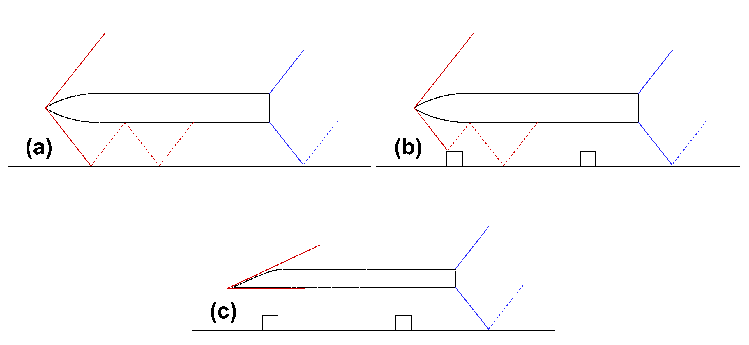
Figure 1. Schematic diagram of shockwaves evolution affected by ground effect (The red lines represent the head shock and reflected shock, and the blue lines represent the expansion waves and reflected expansion waves): (a) without obstacles, (b) with obstacles, (c) with the waverider.
Applsci 12 07861 g001
Figure 2. Circumferential C P distribution on axisymmetric slender body: (a) x/d = 3.5, (b) x/d = 5.5.
Applsci 12 07861 g002
Figure 3. Schematics of two rocket-sleds: (a) ASRS, (b) RWRRS.
Applsci 12 07861 g003
Figure 4. Computational domains of two rocket-sleds.
Applsci 12 07861 g004
Figure 5. Mesh snapshots of two rocket-sleds: (a) ASRS, (b) RWRRS.
Applsci 12 07861 g005
Figure 6. The contours of pressure p/ p at the position of x = 0 in ASRS flow field: (a) t 1 = 0.0180 s, (b) t 2 = 0.0186 s.
Applsci 12 07861 g006
Figure 7. The contours of pressure p/ p at the position of x = 0 in RWRRS flow field: (a) t 1 = 0.0180 s, (b) t 2 = 0.0186 s.
Applsci 12 07861 g007
Figure 8. Pressure p/ p distributions on two rocket-sleds surface from different view: (a) side view of ASRS, (b) side view of RWRRS, (c) top view of ASRS, (d) top view of RWRRS, (e) upward view of ASRS, (f) upward view of RWRRS.
Applsci 12 07861 g008
Figure 9. Coefficient of surface friction C f distribution: (a) top view of ASRS, (b) top view of RWRRS, (c) upward view of ASRS, (d) upward view of RWRRS.
Applsci 12 07861 g009
Figure 10. Comparison of the surface limiting streamline (coloured with streamwise shear stress) distribution: (a) top view of ASRS, (b) top view of RWRRS, (c) upward view of ASRS, (d) upward view of RWRRS.
Applsci 12 07861 g010
Figure 11. Distribution of ρ / y in ASRS flow field at t 1 = 0.0180 s: (a) front section, (b) middle section, (c) rear section.
Applsci 12 07861 g011
Figure 12. Distribution of ρ / y in RWRRS flow field at t 1 = 0.0180 s: (a) front section, (b) middle section, (c) rear section.
Applsci 12 07861 g012
Figure 13. Pressure distribution at the symmetrical section on the surface of ASRS (The gray color describes the shape): (a) t 1 = 0.0180 s, (b) t 2 = 0.0186 s, (c) t 3 = 0.0192 s, (d) t 4 = 0.0198 s.
Applsci 12 07861 g013
Figure 14. Pressure distribution at symmetrical section on the surface of RWRRS (The gray color describes the shape): (a) t 1 = 0.0180 s, (b) t 2 = 0.0186 s, (c) t 3 = 0.0192 s, (d) t 4 = 0.0198 s.
Applsci 12 07861 g014
Figure 15. The curves of lift and drag force over time of two rocket-sleds (The yellow color represents the fluctuation range of ASRS and the green color represents the fluctuation range of RWRRS): (a) lift force, (b) drag force.
Applsci 12 07861 g015
Figure 16. Pressure profile of the probes on the surface of rocket-sleds: (a) ASRS, (b) RWRRS.
Applsci 12 07861 g016
Figure 17. PSD profiles for pressure signals on two rocktet sleds: (a) ASRS, (b) RWRRS.
Applsci 12 07861 g017
Figure 18. Pressure and PSD profiles for pressure signals of detectors: (a) pressure profiles, (b) PSD profiles.
Applsci 12 07861 g018
Figure 19. Comparison of SPL value of probes on two rocket-sleds.
Applsci 12 07861 g019
Table 1. A summary of several common active and passive flow control methods.
PatternMethodsAdvantagesDisadvantages
ActiveJet [22,23,24,25,26]Easy to maintain, cost-effectiveAffects performance and operating life
ActiveStructural deformation [27,28]Adaptable, effectiveComplex, big weight
ActivePeriodic excitation [29,30]Compact construction and energy savingLimited control scope
ActiveHeating [31]Simple structureWeak ability
PassiveChanging surface condition [32,33,34]EffectiveDifficult to adjust and narrow applicability
PassiveAdding extra objects [35,36,37,38]Simple in theoryDifficult to apply
PassiveShape optimization [39,40]Adaptable, effectiveComplex process and limited control scope
Publisher’s Note: MDPI stays neutral with regard to jurisdictional claims in published maps and institutional affiliations.