
Tailoring the V-Model for Optics: A Methodology for Optomechatronic Systems


Abstract
1. Introduction
1.1. Motivation
1.2. Introduction of the Application Example
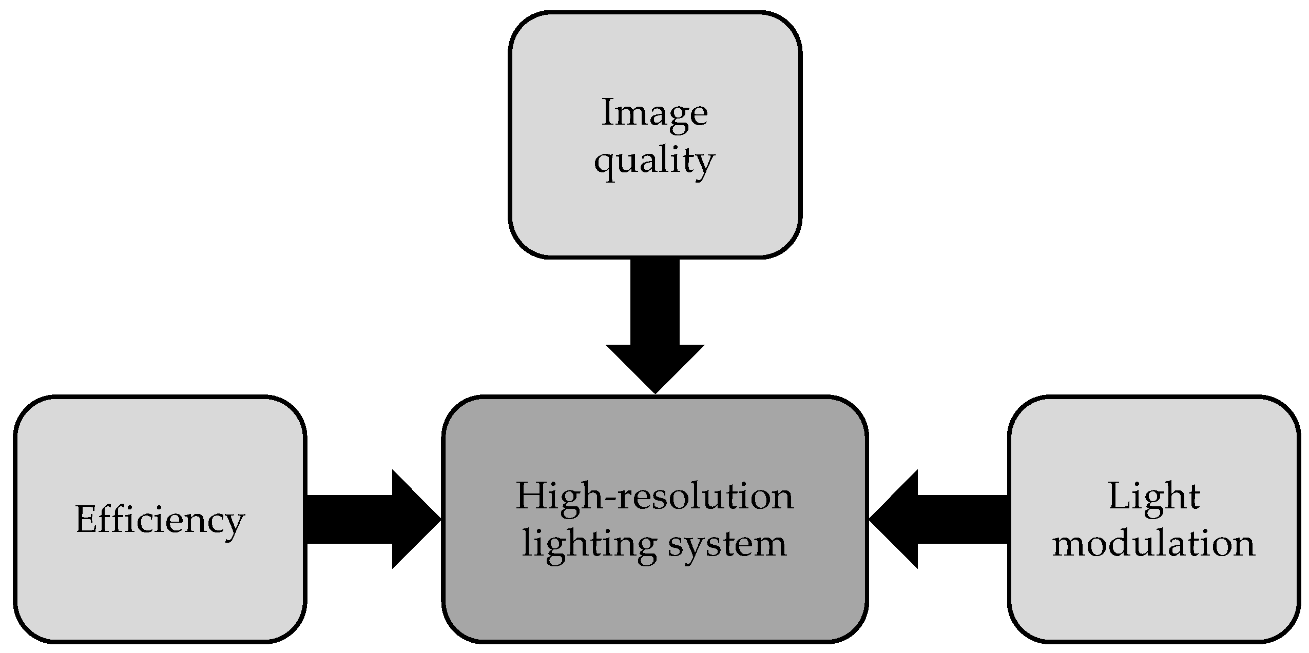
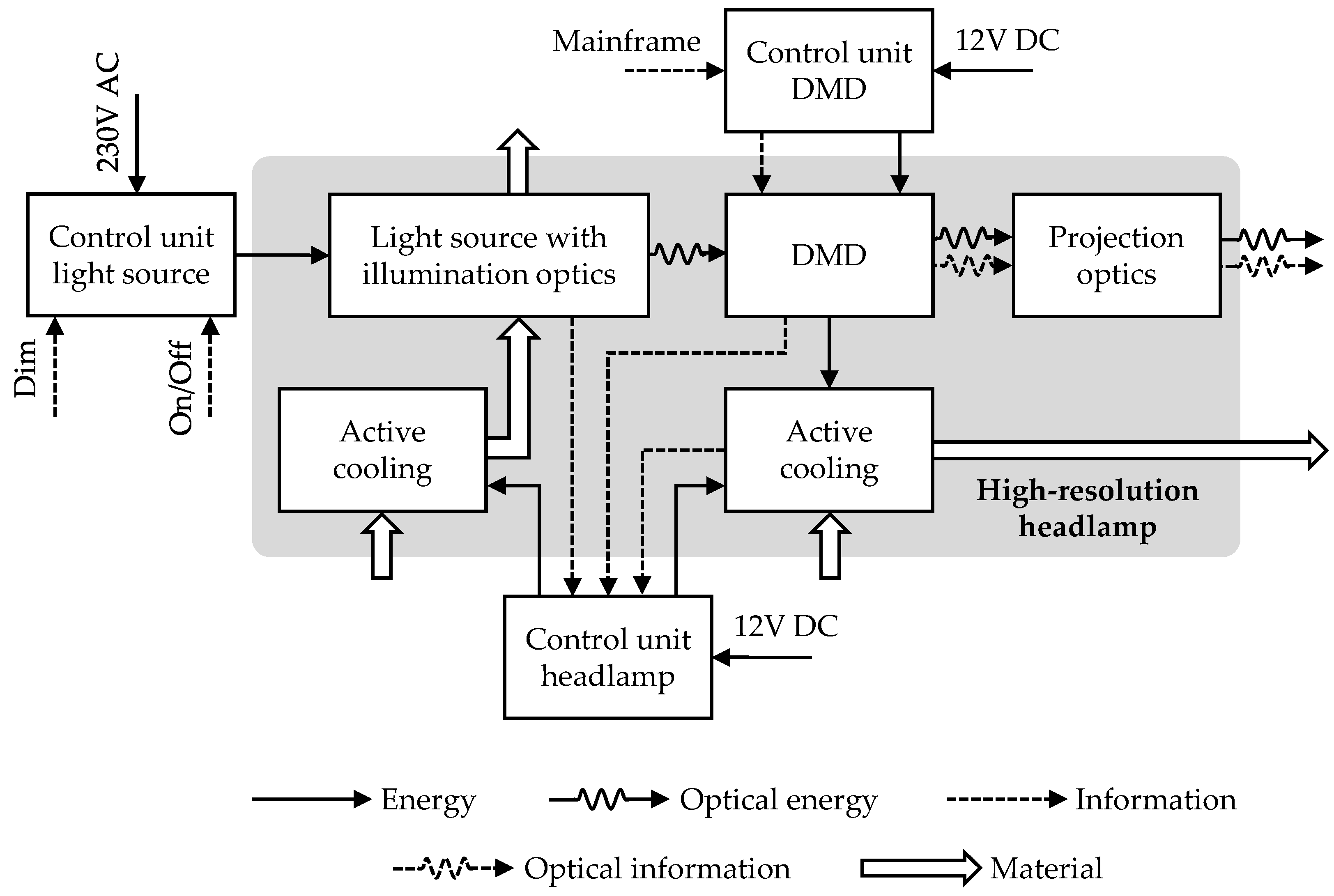
- Efficiency: High-resolution lighting systems for vehicle front lighting require not only high optical efficiency but also high electrical efficiency, so semiconductor light sources such as LEDs and laser diodes are increasingly being used to generate light. However, compared to conventional light sources, semiconductor light sources differ significantly in terms of operation, radiation characteristics and thermal management [32,33,34].
- Image quality: In optical systems, effects such as diffraction, aberration or distortion, which influence the image quality, have to be taken into account. Various measures can be implemented to correct these effects; for example, the combination of several lenses made of different materials. However, since losses occur at each optical element as a result of Fresnel reflections and material defects, which have a negative impact on the optical efficiency of the system, the use of as few optical elements as possible is advantageous. Consequently, a conflict of objectives arises between optical efficiency and image quality of the system [35,36].
- Light modulation: So-called light modulators such as liquid crystal displays (e.g., LCD, LCoS) or digital micromirror arrays are used to generate high resolutions. LED matrices represent another way to develop active lighting systems, but are not in the focus of this contribution due to the significantly lower achievable resolution. While the aforementioned technologies are well established in the field of video projection applications, their deployment in the field of vehicle front lighting is new. When using a DMD, the limited tilt angle of the micromirrors constrains the aperture angle of the incident light beam, which thus limits the maximum luminous flux that can be modulated. The operation of liquid crystal displays is based on the use of polarized light, which results in special requirements for the light source and the use of special optical elements for polarization [37,38].
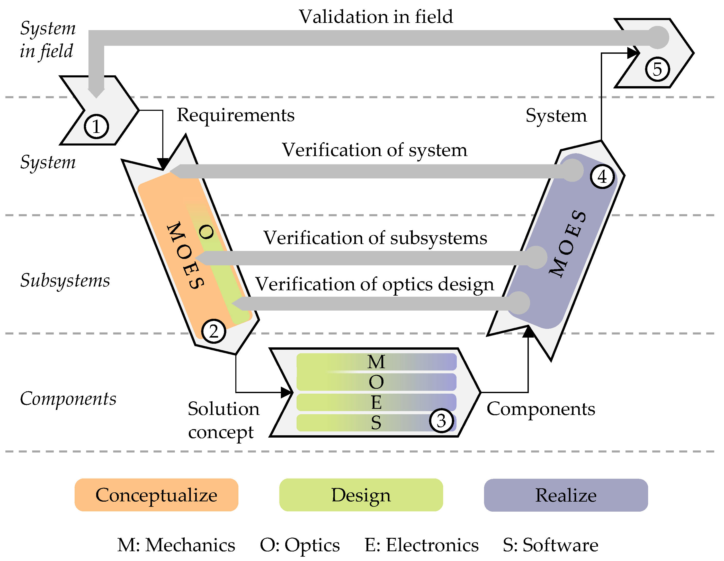
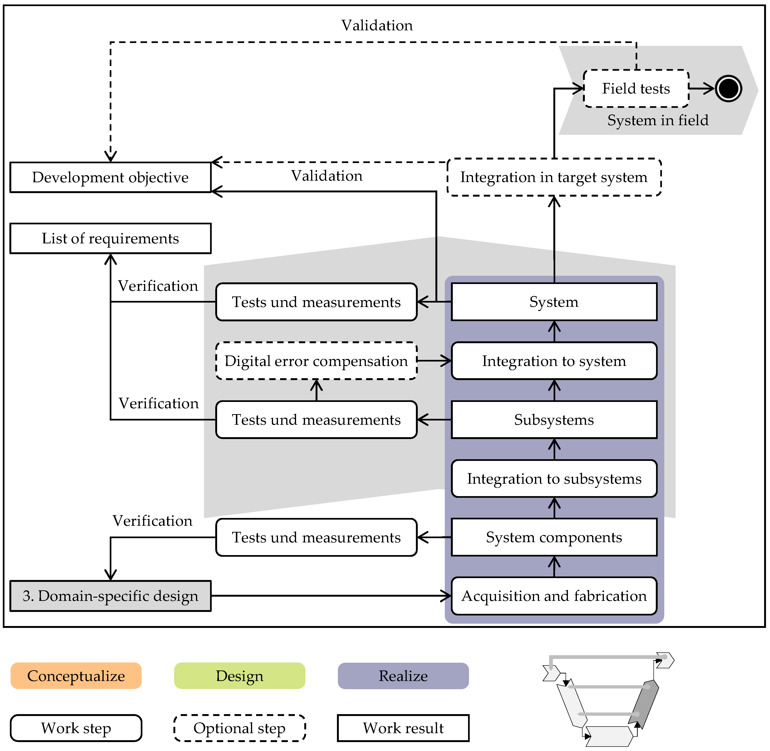
2. V-Model to Develop Optomechatronic Systems
- Applicability for system developments: Optomechatronic systems consist of components of the domains mechanics, electronics, infomation technology and optics. To achieve the specified functional behavior, the focus is particularly on interfaces and interactions between the domains and components of the system [41].
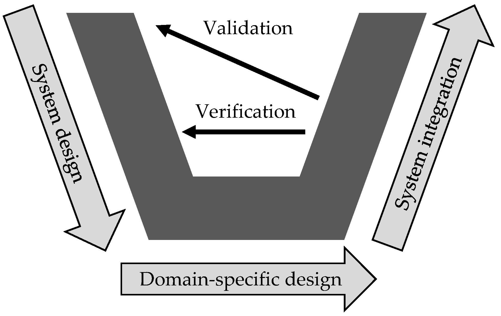
- Linking process elements of micro- and macrology: Within the phases system design, domain-specific design and system integration, the V-Model presented earlier contains three superordinate sections that allow a development project to be classified into work packages and milestones. Lindemann [42] describes this view of a process as macrology. Furthermore, the applicability of a process depends on the definition of tangible work steps that can be assigned to the micrology. The V-Model of VDI guideline 2206 contains detailed work steps for the phases mentioned in order to provide developers with additional orientation [10]. Linking elements of macro- and micrology therefore helps in the development of complex systems and is required for the process to develop optomechatronic systems.
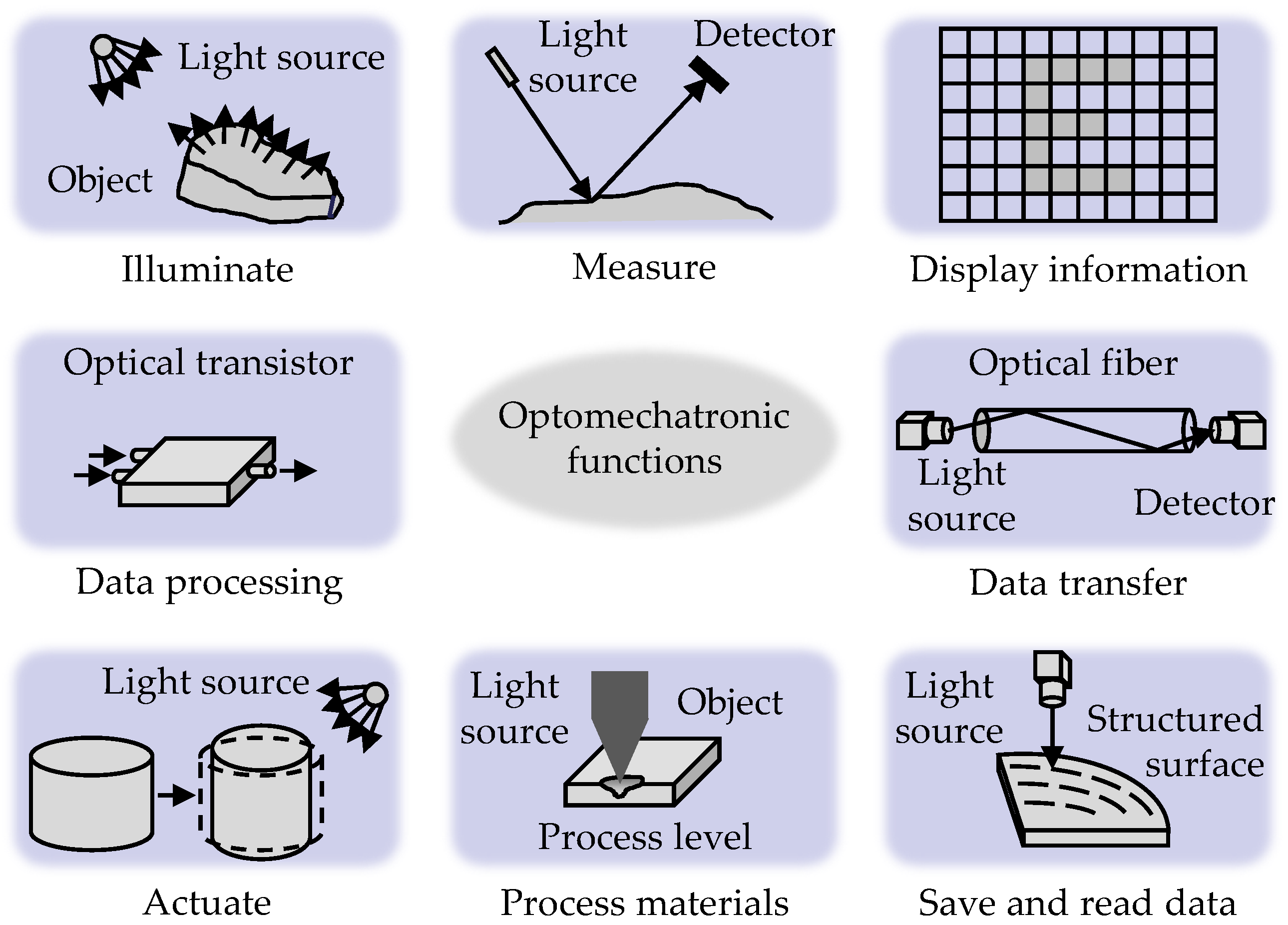
- Consideration of the concept-defining requirements of the optics domain: Changes made in a late phase of system development are associated with high effort and risk. In development methodology, it is therefore recommended that requirements which have a high influence on the system concept in particular be taken into account early in the development process [43]. In the optomechatronic systems discussed in this contribution, the functions “Illuminate” and “Display information” (cf. Figure 1) are the focus of the conceptual consideration. The requirements for the optical function should therefore be analyzed particularly early in the development process and implemented in a solution concept.
- Consideration of effects on humans: Effects on humans are a particular focus for illuminating optical systems. As part of the main function, those effects can be intended and part of the development goal, but they can also imply an unwanted disturbing effect. A further requirement for the development process is therefore the explicit consideration of the interactions of the system with humans.
3. Concretization of the V-Model for High Resolution Lighting Systems
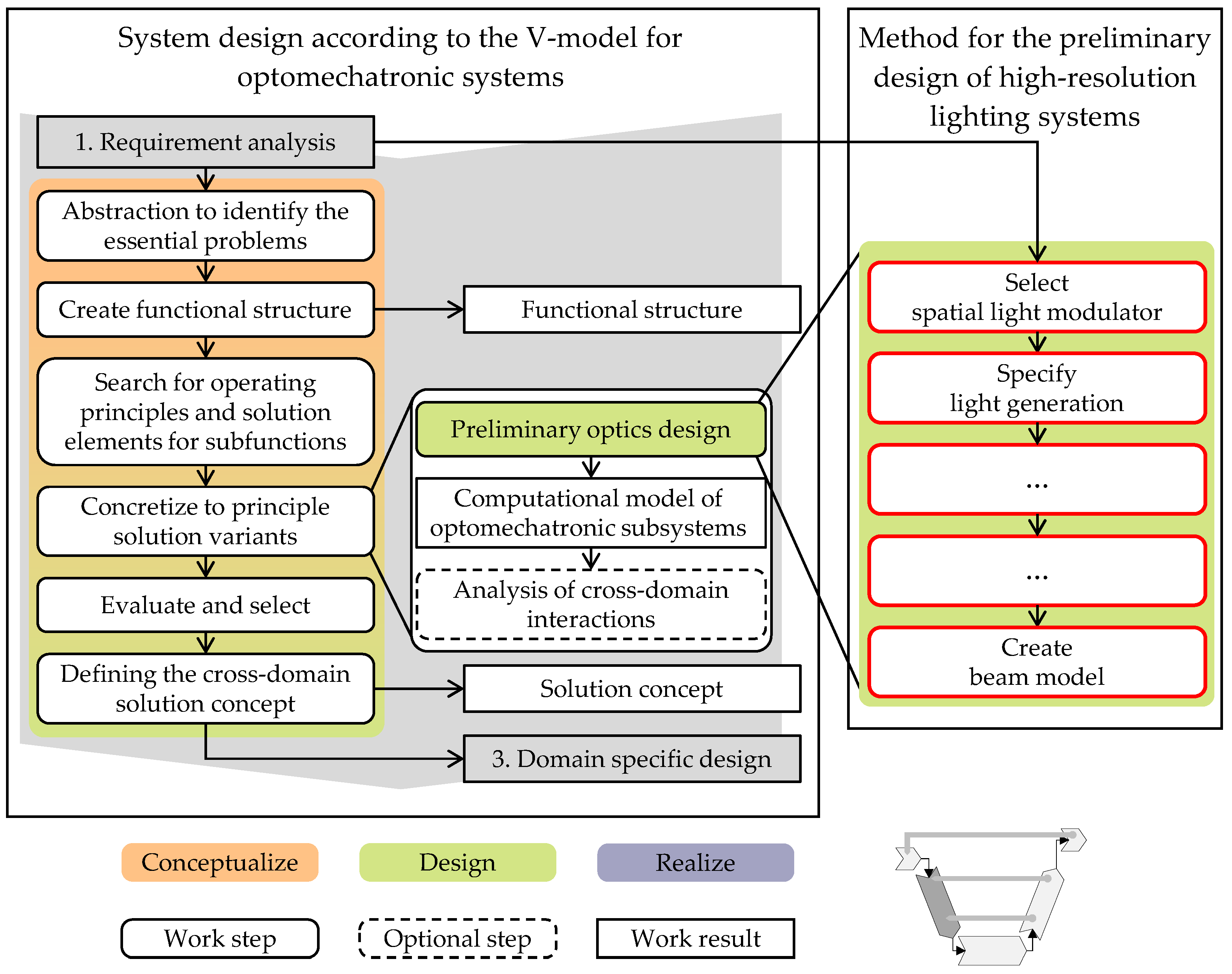
3.1. Extension of the System Design Process Phase to Include the Method for the Preliminary Design of High-Resolution Lighting Systems
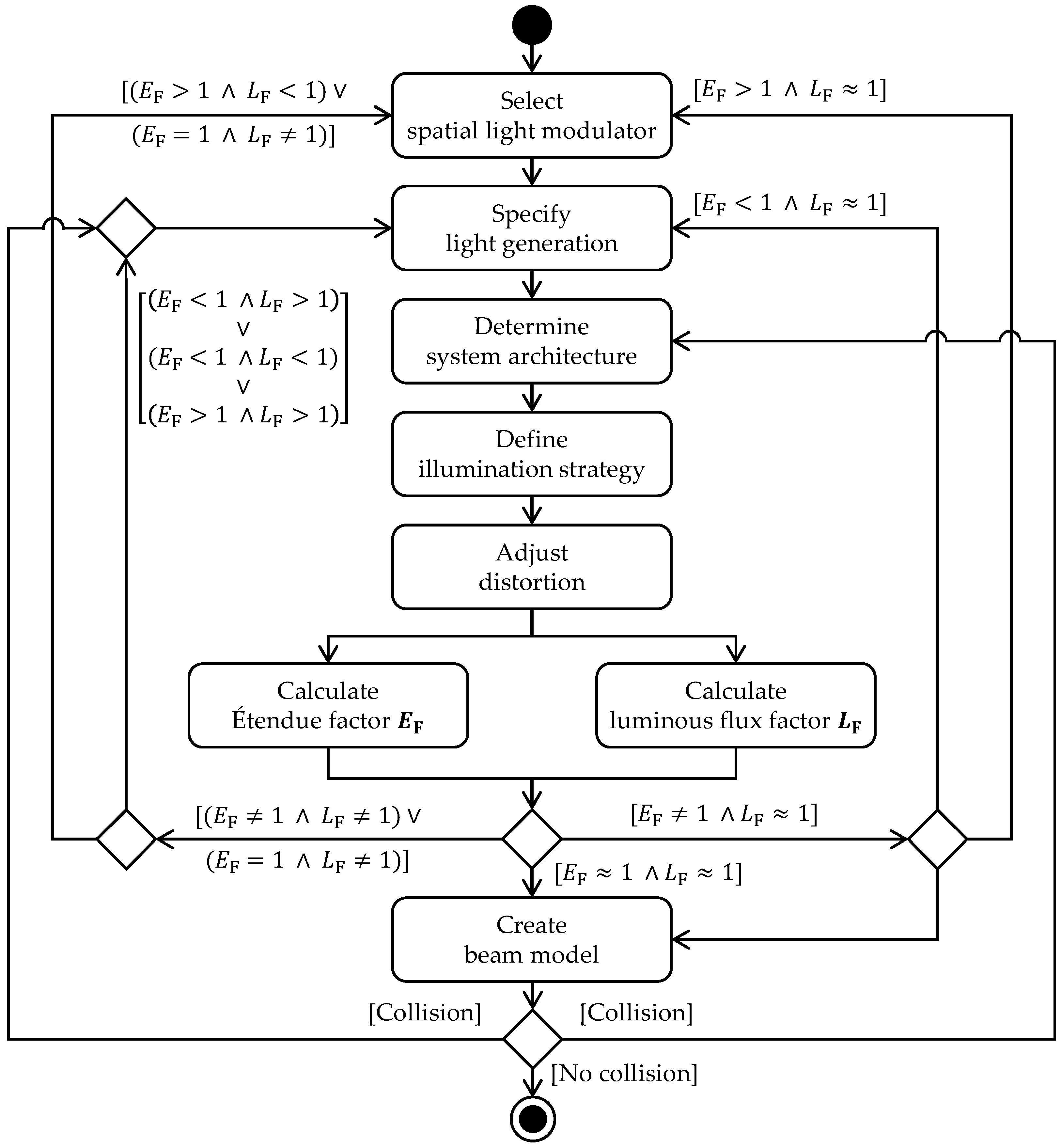
- Select spatial light modulator: For the preliminary design of a high-resolution lighting system, we first need to define the Étendule-limiting component, which in this case is the light modulator. If no specific technology for light modulation (e.g., LCD or DMD) has been defined within the scope of the requirements elicitation; this is carried out in this step. Criteria for selecting a suitable technology may include resolution, contrast or efficiency. Furthermore, the aspect ratio and the number of light modulators to be used must be defined. Based on the luminous flux in the light distribution to be generated and an initially assumed efficiency of the subsystem used for projection into the traffic area, the minimum required Étendue of the light modulator can be determined. Since the functional principle of the modulator determines its acceptance angle, the active area required for modulation can be determined accordingly.
- Specify light generation: For the illumination of the active area of the selected light modulator, a suitable technology for light generation (discharge lamp, electroluminescent emitter, etc.) has to be specified, if not already done in the requirements elicitation. Then, based on the Étendue of the light modulator, the number of light sources to be used and the size of the emission areas need to be determined. Neglecting Fresnel reflections and scattering in the optical system, an efficient light system can be assumed if the Étendue of light source and light modulator are equivalent.
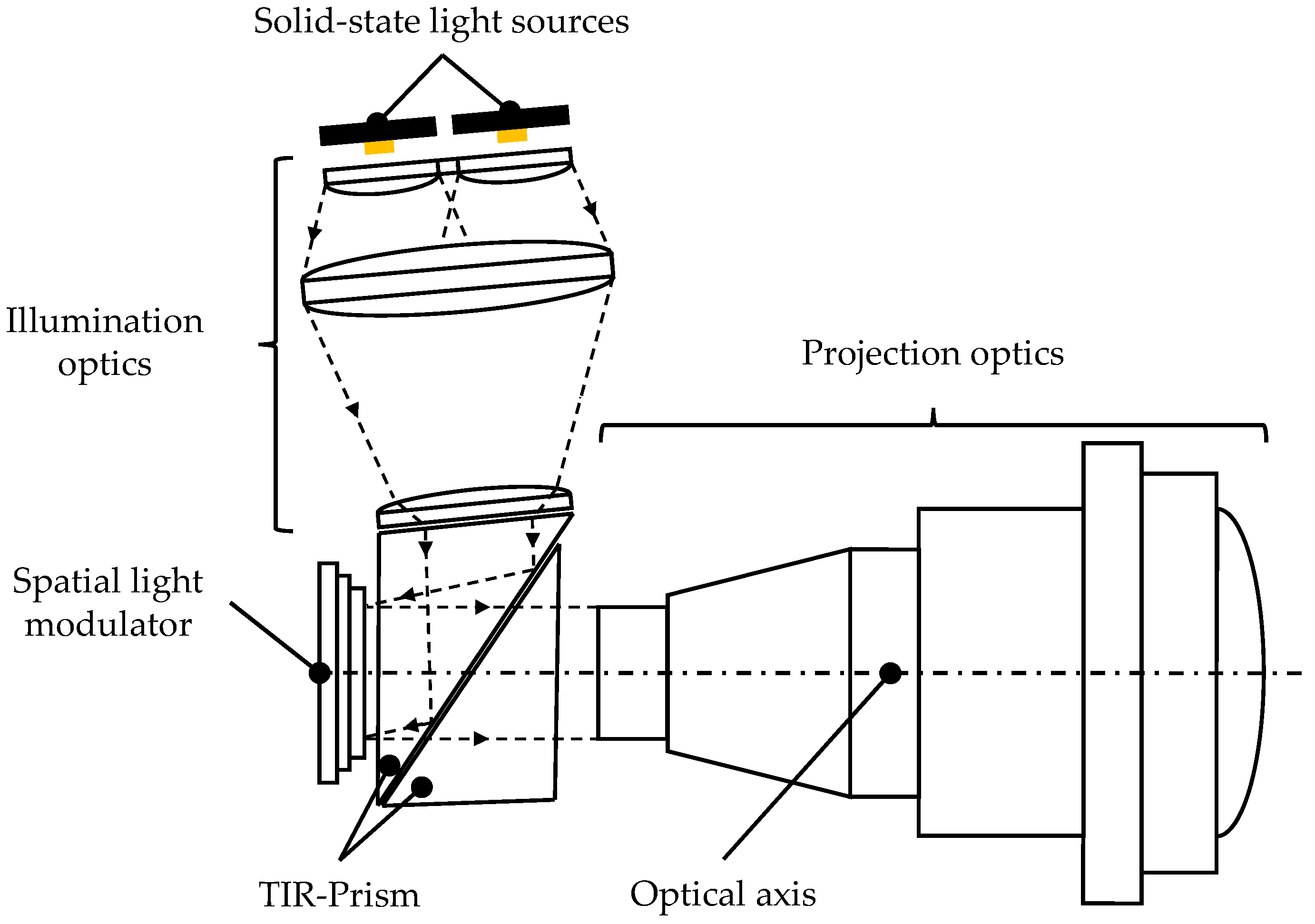
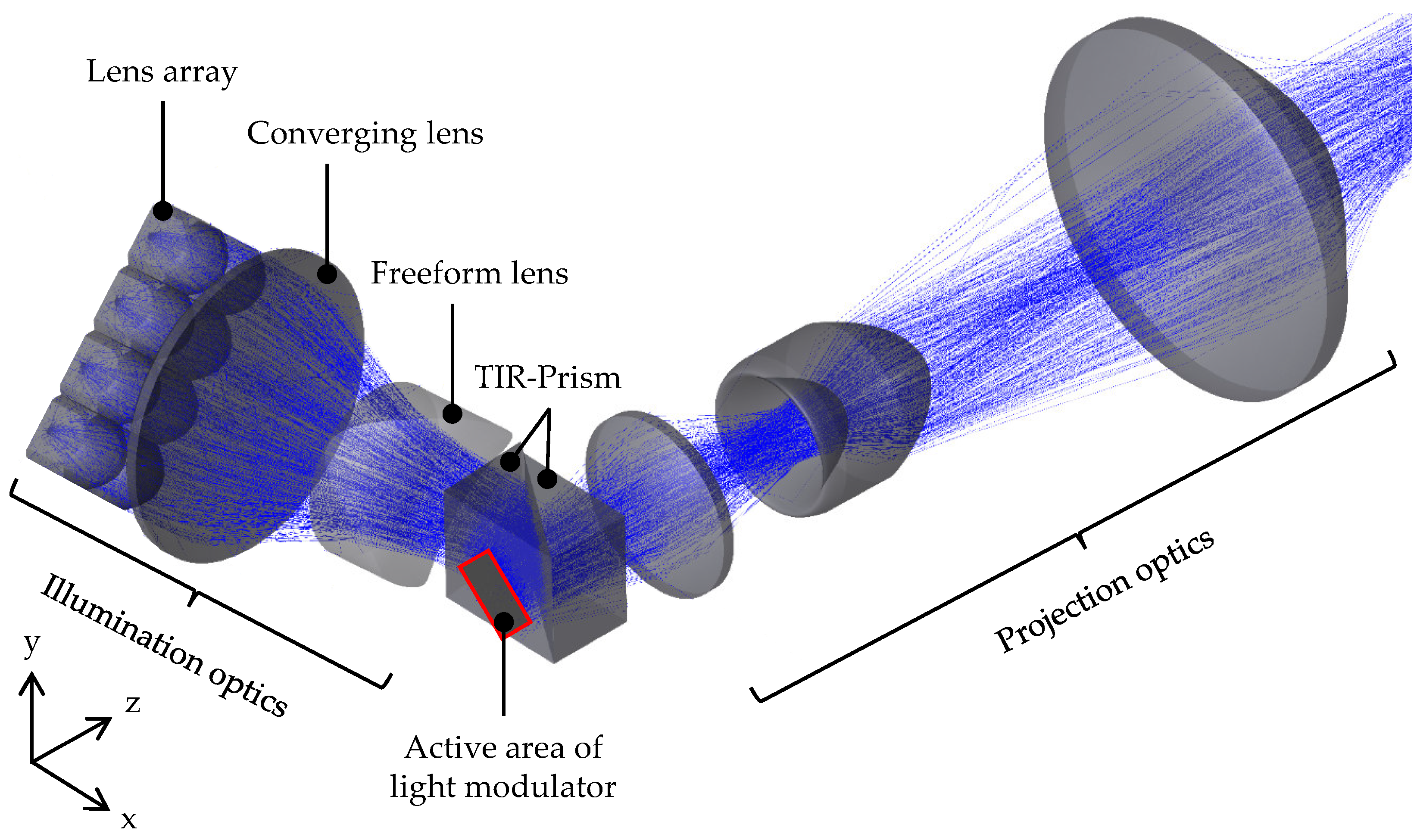
- Determine system architecture: When determining the architecture of the high-resolution lighting system, not only the type and number of optical elements to be used for beam shaping and deflection are specified, but also the spatial arrangement of these elements required for implementation. Depending on the defined technologies for light modulation and generation as well as on the elicited requirements, different system architectures are feasible. Using a light modulator, the optical system of a high-resolution lighting system can be divided into a subsystem to illuminate the light modulator and a subsystem to project it into the application area. Both subsystems are functionally as well as spatially interdependent. Functional dependence arises from the strategy to illuminate the active area of the modulator (cf. paragraph Define illumination strategy) and the lighting of the projection area (cf. paragraph Adjust distortion). The spatial dependence derives from the chosen technology for light modulation, which at the same time affects the Étendue of the system. For example, when using a DMD to implement a non-telecentric system architecture, higher angles are required to illuminate the light modulator in order to achieve sufficient separation of the incident light from the illumination system and the light reflected into the projection system than with a telecentric system architecture. As the illumination angle increases, the seemingly illuminated area of the light modulator is reduced, thus reducing the Étendue of the DMD.
- Define illumination strategy: Strategies to illuminate the active area of the modulator can be differentiated primarily into imaging and non-imaging and secondarily into homogeneous and inhomogeneous [31,57]. According to photometric regulations for headlamps, which are specified in various ECE regulations, an inhomogeneous distribution of illuminance within the traffic area is required [58,59,60]. Therefore, it seems to be obvious to use an inhomogeneous strategy to illuminate the active area of the modulator. However, an inhomogeneous illuminance distribution of the active area of the modulator, regardless of whether it is generated imaging or non-imaging, can lead to a damage of individual micromirrors or of the entire light modulator due to the irregular heat input in case of insufficient cooling. Using imaging illumination strategies, a precise illumination of the active area of the modulator is possible given appropriate manufacturing and assembly tolerances of the optical and mechanical components. Luminous flux losses, which occur when using non-imaging illumination strategies due to illumination overfill of the active area of the modulator [61,62], are therefore reduced. However, as a result of the functional dependence between the illumination and projection optics, the overall efficiency of high-resolution lighting systems for vehicle front illumination can be increased using a distortion of the projection system adjusted to the inhomogeneous illumination strategy [63].
- Adjust distortion: In order to meet the photometric requirements, a distortion of the projection optics is determined that is adjusted to the illumination strategy, taking into account the subsystem that illuminates the active area of the modulator. Usually an aberration in optical systems, distortion does not lead to blur but to a distortion of the projected image and thus to a positionally variant image scale [64,65]. For example, anamorphic distortion can be used to change the image scale in horizontal and/or vertical direction. Thus, the geometry of the illuminated area can be decoupled from the aspect ratio of the light modulator [12,63]. In addition to a variable pixel size, a pincushion distortion also enables a redistribution of the illuminance, which benefits the application as a headlamp [66,67].
- Calculate Étendue factor: To evaluate the Étendue conservation and thus the efficiency of the high-resolution lighting system, the so-called Étendue factor is defined. Defined as the ratio of the Étendue of the light source to the Étendue of the light modulator [68], efficient preliminary designs are indicated by an Étendue factor of approximately one . Inefficient preliminary designs are characterized by an Étendue factor of significantly greater or less than one. However, since both an efficient and inefficient preliminary design cannot be considered equivalent to the fulfillment or non-fulfillment of photometric requirements, a so-called luminous flux factor is also defined.
- Calculate luminous flux factor: The luminous flux factor is used to ensure the preliminary design with regard to the feasibility of photometric requirements and is described by the ratio of actual to target luminous flux on the active area of the modulator. The target luminous flux is determined using the required luminous flux in the light distribution based on assumptions about the efficiency of the subsystem for projection as well as the illumination overfill of the active area of the modulator. The actual luminous flux is determined using the Étendue and thus the usable portion of the luminous flux from the light source to illuminate the active area of the modulator, as well as assumptions about the efficiency of the subsystem used for illumination. For preliminary designs indicated by a luminous flux factor of approximately and greater than one , the photometric requirements can be realized. Preliminary designs indicated by a luminous flux factor of significantly less than one , the photometric requirements cannot be met.
- Case analysis: Within the scope of the case analysis shown in Figure 7, the developed preliminary designs are evaluated with regard to the conservation of Étendue and the fulfillment of photometric requirements. The occurring cases can be divided into the following three categories:
- -
- Category 1 is associated with cases , where the photometric requirements cannot be realized due to a too low luminous flux factor;
- -
- For preliminary designs of category 2 , the photometric requirements are met, but due to an Étendue factor considerably differing from one, these designs are characterized by inefficiency. Consequently, either the light source or the light modulator is oversized;
- -
- If the photometric requirements and simultaneously the Étendue conservation are fulfilled, then the preliminary designs are of category 3 , allowing to proceed directly to the last design step of the method.
For category 1 and 2 designs, loops are provided within the method to return to specific design steps for targeted optimization. An explanation of when to return to which design step can be found in [17]. - Create beam model: In the final step, a beam model is created for the preliminary design of the high-resolution lighting system, which serves as the basis for the domain-specific detailed design of the optical system. The beam path of the high-resolution lighting system is designed from the light source on the object side to the projection area on the image side. Furthermore, the beam model can be used to identify system configurations in which, for example, individual optical elements or the subsystems for illumination and for projection collide. Occurring collisions can be resolved via loops within the method to the steps “Determine system architecture” and “Specify light generation”, which is explained in more detail in [17].
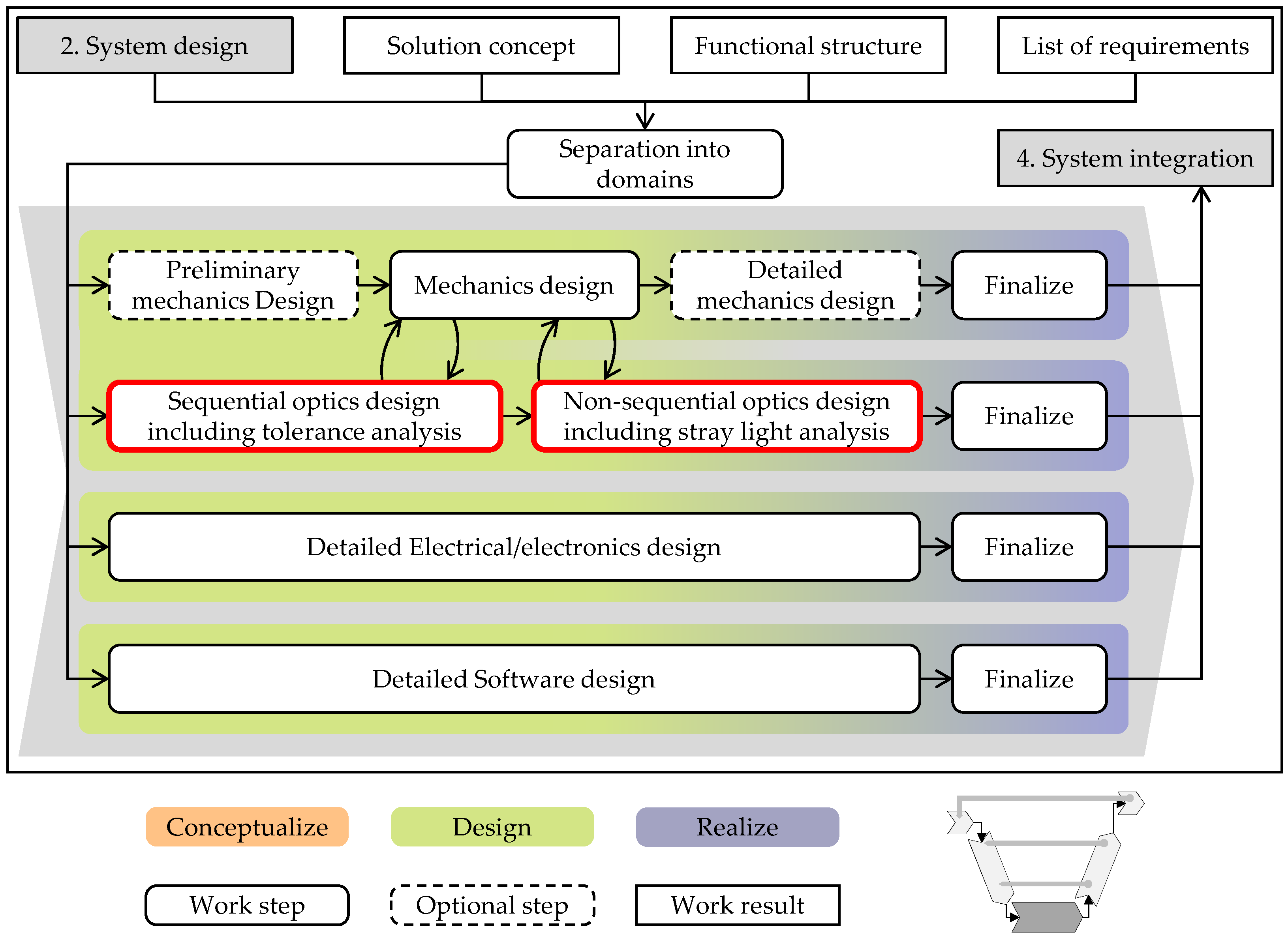
3.2. Extension of the Process Phase for Domain-Specific Design by the Method for the Detailed Design of High-Resolution Lighting Systems
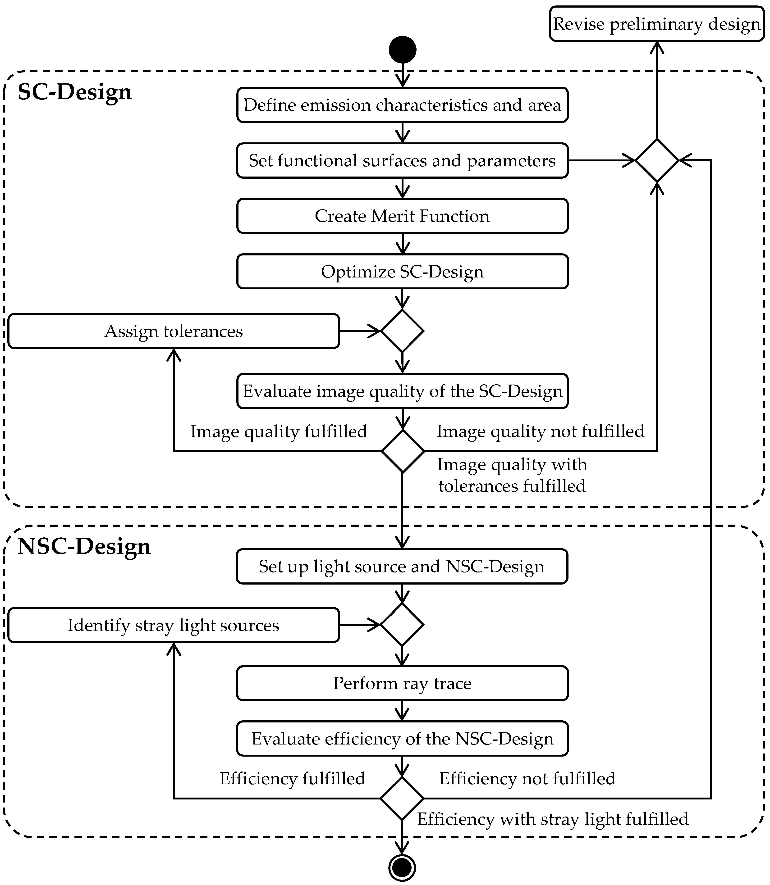
3.2.1. Design Steps for the Sequential Detailed Design (SC-Design)
- Define emission characteristics and area: Reduced to individual emission points—so-called fields, from which the spatial propagation of the rays emitted by the light source occurs—the size of the emission area is defined. For the description of the emission area, the arrangement of several fields is beneficial in order to achieve a high accuracy in ray shaping of the subsequent functional surfaces. Rays, which shall be considered by the following functional surface (e.g., mirror or surface of a lens) for shaping or deflection, can be defined by the emission angle of the fields as well as by the entrance pupil or numerical aperture of the functional surface. In addition, for both monochromatic and polychromatic light sources, the wavelength(s) must be specified.
- Set functional surfaces and parameters: Based on the parameters obtained from the beam model, such as the type and number of optical elements for beam shaping and deflection, as well as the focal length and the image scale, the functional surfaces, parameters and boundary conditions of the optical system can be defined. Refractive optical elements such as lenses or prisms are defined by the combination of two respectively three functional surfaces in Zemax OpticStudio®. The thickness of the optical element and the material are determined by the first functional surface. Reflective optical elements such as reflectors or plane mirrors are defined by a single functional surface, specifying reflective material properties. Once all functional surfaces for the sequential detailed design have been defined, functional surface parameters such as radii, materials or distances, which may or may not be changed during the optimization of the detailed design, are defined. To obtain a first approximation, it is advantageous to limit the number of variable parameters in the early phase of the detailed design. With increasing maturity of the sequential detailed design, the number of variable parameters of the functional surfaces can be increased in context of optimization loops. The parameter values should be limited in consideration of manufacturability and mountability of the optical elements. Finally, boundary conditions are defined, which arise in particular from the requirements initially elicited.
- Create Merit Function: As an expression of design objectives to be met and achieved, a so-called merit function must first be defined for the optimization of the sequential detailed design. By restricting variable parameters due to minimum and/or maximum values, design goals to be met are defined. This may lead to several valid design solutions during optimization. An example is the length of the optical system, which should not exceed a certain maximum value due to requirements. Thus, with respect to the maximum length of the optical system, several designs can be developed to meet this requirement. If the variable parameters are defined by a single value, these are design goals to be achieved, with only one valid design solution. As an example of design objectives to be achieved, a defined field of view, which has to be illuminated according to the requirements, can be mentioned at this point. Design objectives to be met and achieved, which are derived from the requirements for the sequential detailed design, are thus coupled to the freedoms in the merit function, which in turn correlate with the number of variable parameters.
- Optimize SC-Design: Within the optimization step, the optimization type, the optimization algorithm and the number of optimization cycles have to be defined. The type of optimization can be divided into so-called “local” and “global” optimization [53]. In the early phase of the design process, “global” optimization is particularly suitable for an initial estimation. As the sequential detailed design matures, effective improvements can be achieved quickly using “local” optimizations. The algorithm for the optimization of the detailed design has to be chosen depending on the function of the optical system (imaging or illuminating) as well as on the selected optimization type. Especially developed for detailed designs of optical systems, algorithms that operate according to the “Damped Least Squares” method are generally suitable [71]. The number of optimization cycles to be performed has to be defined depending on the design progress. Similar to the definition of variable parameters, a limited number of cycles is recommended in the early phase of the design process, which can be increased with the growing maturity of the sequential detailed design.
- Evaluate image quality of the SC-Design: On the basis of the design of an imaging optical system, the image quality of the sequential detailed design must be evaluated after the optimization step. For the design of illumination optics, this step can be skipped. Different criteria such as modulation transfer function (MTF), point spread function (PSF), encircled energy (EE), RMS spot radius, wavefront, and aberrations are used to evaluate the image quality [51,52,72,73]. The choice or suitability of an evaluation criterion is significantly influenced by the subsequent field of application of the optical system. For example, detailed designs of lenses used in the field of photography are evaluated using the MTF, and optical designs of LiDAR systems are often evaluated using the EE criterion [74,75,76,77]. In case the required image quality of the sequential detailed design is not met, return to step “Set functional surfaces and parameters” (cf. Figure 9). If the requirements for the image quality are not met despite repeated runs through this loop, the preliminary design of the high-resolution lighting system must be revised (cf. Figure 9).
- Assign tolerances: Since deviations due to manufacturing and alignment affect the image quality of the sequential detailed design, tolerances must be assigned to the individual functional surfaces and the image quality must be re-evaluated. Deviations caused by the manufacturing process (ultra-precision turning, CNC machining, etc.) must be taken into account by tolerancing the detailed design with regard to the position and surface of the functional surfaces. The influence of alignment-related deviations of individual optical elements in the manufactured optical system can be taken into account by decentering and tilting the functional surfaces in the sequential detailed design. If the requirements for the image quality of the sequential detailed design are met, while taking the assigned tolerances into account, one can continue with the assembly of the non-sequential detailed design. Otherwise, return to the step “Set functional surfaces and parameters”.
3.2.2. Steps for the Non-Sequential Detailed Design (NSC-Design)
- Set up light source and NSC-Design: The simplified emission characteristics and area of the light source of the sequential detailed design is replaced by a so-called ray file, from which the measured spatially resolved radiance of the light source from different angular positions is described [78]. Alternatively, a modeling of the light source with appropriate angular and spatial resolution of the luminous intensity can be carried out according to the data sheet. Subsequently, the number of rays required for tracing has to be determined, which should be high in terms of an accurate conclusion about the efficiency. Furthermore, the luminous flux of the source, as well as the emitted wavelength(s), have to be specified. For precise statements about the efficiency of the high-resolution lighting system, not only the light source but also the light modulator must be modeled as accurately as possible, and material, coating and scattering definitions must be assigned to the optical volume elements (lenses, prisms, etc.).
- Perform ray trace: Taking into account the angular and spatially resolved luminous intensity of the light source, a defined number of rays are traced through the optical system. The single rays are affected by different optical effects like refraction, diffraction, (total) reflection, scattering, splitting or absorption or a combination of these effects, which depend on the assigned material, coating and scattering definitions as well as on the individual optical elements.
- Evaluate efficiency of the NSC-Design: The evaluation of the efficiency of the non-sequential detailed design is carried out on the basis of the performed ray trace. In addition to determining the overall efficiency, it is also recommended to determine the efficiencies of the individual optical elements in order to be able to conduct targeted measures to increase efficiency during optimization loops. If the overall efficiency and/or the photometric requirements (e.g., lighting functions to be realized or photometric quantities) of the high-resolution lighting system are not met, it is advisable to return to the design step “Functional surfaces, parameters and boundary conditions”. If no improvement is achieved despite running through this loop several times, a second loop must be used to return to the phase of preliminary design (cf. Figure 9).
- Identify stray light sources: In order to identify unwanted scattered and reflected light, which may have negative effects on the optical properties of the non-sequential detailed design, a stray light analysis must be performed. Both optical and mechanical components that lead to an unwanted reduction in contrast and/or image quality are analyzed. An effective approach to identify stray light at surfaces of the optical and optomechanical design is to examine the optical system from the object and image sides. For this purpose, based on the previously performed ray trace, selected rays are analyzed with respect to their interaction with surfaces and subsequently measures for the reduction of stray light are implemented. According to Breault [79], the application of anti-reflective coatings, the positioning of aperture stops at suitable points in the optical path or the constructive redesign of individual components are particularly effective measures for the reduction of stray light. The exchange of information between the optics and mechanics domain is therefore essential with regard to the respective domain-specific design (cf. Figure 8). The effectiveness of the implemented measures shall be verified by means of a repeated ray trace with subsequent evaluation of the efficiency. If the requirements for the efficiency of the non-sequential detailed design are met, the method ends.
3.3. System Integration and Property Validation Process Phase
4. Application Example
4.1. System Design: Cross-Domain Solution Concept of a High-Resolution Lighting System
4.2. Domain-Specific Design: Non-Sequential Detailed Design of a High-Resolution Lighting System
5. Summary and Conclusions
Author Contributions
Funding
Institutional Review Board Statement
Informed Consent Statement
Data Availability Statement
Conflicts of Interest
References
- Cho, H. Optomechatronics: Fusion of Optical and Mechatronic Engineering; Mechanical Engineering Series; CRC Taylor & Francis: Boca Raton, FL, USA, 2005. [Google Scholar]
- Kaden, T.; Janschek, K. Modelica-Bibliothek für diffraktive Optik zur Modellierung von optomechatronischen Systemen. at-Automatisierungstechnik 2014, 62, 423–435. [Google Scholar] [CrossRef]
- Liu, K. Opto-mechatronics: A new concept of system design. In Applications of Photonic Technology 2; Lampropoulos, G.A., Lessard, R.A., Eds.; Springer: Boston, MA, USA, 1997; pp. 145–147. [Google Scholar] [CrossRef]
- Cho, H. (Ed.) Opto-Mechatronic Systems Handbook: Techniques and Applications; The Mechanical Engineering Handbook Series; CRC Press: Boca Raton, FL, USA, 2003. [Google Scholar]
- Kanngiesser, J.; Rahlves, M.; Roth, B. Double Interferometer Design for Independent Wavefront Manipulation in Spectral Domain Optical Coherence Tomography. Sci. Rep. 2019, 9, 14651. [Google Scholar] [CrossRef] [PubMed]
- Fricke, D.; Denker, E.; Heratizadeh, A.; Werfel, T.; Wollweber, M.; Roth, B. Non-Contact Dermatoscope with Ultra-Bright Light Source and Liquid Lens-Based Autofocus Function. Appl. Sci. 2019, 9, 2177. [Google Scholar] [CrossRef]
- Dudko, U.; Overmeyer, L. Optical Wake-Up From Power-Off State for Autonomous Sensor Nodes. IEEE Sens. J. 2021, 21, 3225–3232. [Google Scholar] [CrossRef]
- Schneider, D.; Shrotri, A.; Flatt, H.; Stübbe, O.; Wolf, A.; Lachmayer, R.; Bunge, C.A. Impact of industrial environments on visible light communication. Opt. Express 2021, 29, 16087–16104. [Google Scholar] [CrossRef] [PubMed]
- Knöchelmann, M. Prozess zur Entwicklung Optomechatronischer Systeme. Ph.D. Thesis, Leibniz Universität Hannover, Hannover, Germany, 2021. [Google Scholar] [CrossRef]
- VDI 2206; Development of Mechatronic and Cyber-Physical Systems. Beuth Verlag GmbH: Berlin, Germany, 2021.
- Schlöder, U.; Albrecht, K.F. Headlamp DMD-Technology with High Resolution on the Road. In Proceedings of the SIA VISION Conference, Paris, France, 9–10 October 2018; SIA: Milan, Italy, 2018. [Google Scholar]
- Held, M.P. Hochauflösende LED-Scheinwerfer für Kraftfahrzeuge. Ph.D. Thesis, Gottfried Wilhelm Leibniz Universität Hannover, Hannover, Germany, 2020. [Google Scholar]
- Kloppenburg, G. Scannende Laser-Projektionseinheit für die Fahrzeugfrontbeleuchtung. Ph.D. Thesis, Leibniz Universität Hannover, Hannover, Germany, 2017. [Google Scholar] [CrossRef]
- Li, Y. Laser High-Resolution Vehicle Headlamps. Ph.D. Thesis, Leibniz Universität Hannover, Hannover, Germany, 2020. [Google Scholar]
- Kloppenburg, G.; Wolf, A.; Lachmayer, R. High-resolution vehicle headlamps: Technologies and scanning prototype. Adv. Opt. Technol. 2016, 5, 147–155. [Google Scholar] [CrossRef][Green Version]
- Ley, P.P.; Knöchelmann, M.; Kloppenburg, G.; Lachmayer, R. Development Methodology for Optomechatronic Systems Using the Example of a High-Resolution Projection Module. Proc. Des. Soc. Int. Conf. Eng. Des. 2019, 1, 2547–2556. [Google Scholar] [CrossRef][Green Version]
- Ley, P.P. Konzipieren und Entwerfen Hochauflösender Lichtsysteme am Beispiel eines DMD-Scheinwerfers. Ph.D. Thesis, Leibniz Universität Hannover, Hannover, Germany, 2021. [Google Scholar] [CrossRef]
- Fürst, S.; Scharnhorst, T.; Brabetz, L.; Beck, M.; Lahmeyer, R.; Krieger, O.; Kasties, G.; Pfaff, W.; Lachmayer, R.; Abel, H.B.; et al. Digitalisierung/Elektrik/Elektronik/Software. In Vieweg Handbuch Kraftfahrzeugtechnik; Pischinger, S., Seiffert, U., Eds.; ATZ/MTZ-Fachbuch, Springer Vieweg: Wiesbaden/Heidelberg, Germany, 2021; pp. 861–1008. [Google Scholar] [CrossRef]
- Zydek, B.; Schiller, C.; Polin, D.; Khanh, T.Q. Bewertung von Scheinwerfern mit blendfreiem Fernlicht. ATZ Automob. Z. 2014, 116, 64–69. [Google Scholar] [CrossRef]
- Roth, J.; Wallaschek, J.; Kloppenburg, G.; Lachmayer, R.; Meyer, B.; Thomschke, S. RGB-Laser Scanning Module for Onroad Projection. In Proceedings of the 11th International Symposium on Automotive Lighting, Darmstadt, Germany, 28–30 September 2015; Khanh, T.Q., Ed.; Herbert Utz Verlag GmbH: München, Germany, 2015; Volume 16, pp. 385–394. [Google Scholar]
- Budanow, M.; Neumann, C. Road projections as a new and intuitively understandable human-machine interface. Adv. Opt. Technol. 2019, 8, 77–84. [Google Scholar] [CrossRef]
- Knöchelmann, M.; Ley, P.P.; Kloppenburg, G.; Mozgova, I.; Lachmayer, R. Methodische Entwicklung Eines Opto-Mechatronischen Systems am Beispiel Eines Hochadaptiven Fahrzeugscheinwerfers; Tagungsband der VDI Fachtagung Mechatronik 2019; Universität Paderborn: Paderborn, Germany, 2019. [Google Scholar] [CrossRef]
- Krieft, F.; Thoma, A.; Willeke, B.; Kubitza, B.; Kaup, M. Symbol Projections: Gain or Gadget? In Proceedings of the 13th International Symposium on Automotive Lighting (ISAL), Darmstadt, Germany, 23–25 September 2019; Khanh, T.Q., Ed.; Herbert Utz Verlag: München, Germany, 2019; Volume 18. [Google Scholar]
- Krahnstöver, A.Z. Licht führt!? Springer Fachmedien Wiesbaden: Wiesbaden, Germany, 2017. [Google Scholar] [CrossRef]
- Glück, T.; Biermann, T.; Wolf, A.; Budig, S.; Ziebehl, A.; Knöchelmann, M.; Lachmayer, R. Distraction Potential of Vehicle-Based On-Road Projection. Appl. Sci. 2021, 11, 12030. [Google Scholar] [CrossRef]
- Hamm, M.; Huhn, W.; Reschke, J. Ideas for Next Lighting Generations in Digitalization and Autonomous Driving. In SAE Technical Paper Series; SAE International: Warrendale, PA, USA, 2018. [Google Scholar] [CrossRef]
- Knöchelmann, M.; Held, M.P.; Kloppenburg, G.; Lachmayer, R. High-resolution headlamps—Technology analysis and system design. Adv. Opt. Technol. 2019, 8, 33–46. [Google Scholar] [CrossRef]
- Roelandt, S.; Bogaert, L.; Meuret, Y.; Avci, A.; de Smet, H.; Thienpont, H. Color uniformity in compact LED illumination for DMD projectors. In Optics, Photonics, and Digital Technologies for Multimedia Applications; Schelkens, P., Ebrahimi, T., Cristóbal, G., Truchetet, F., Saarikko, P., Eds.; SPIE: Bellingham, DC, USA, 2010; p. 77230X. [Google Scholar] [CrossRef]
- Sun, W.S.; Pan, J.W. Non-telecentric projection lens design for an LED projector. Appl. Opt. 2017, 56, 712–720. [Google Scholar] [CrossRef]
- Texas Instruments. DLP™ System Optics: Application Report DLPA022; Texas Instruments: Dallas, TX, USA, 2010. [Google Scholar]
- Ley, P.P.; Lachmayer, R. Imaging and non-imaging illumination of DLP for high resolution headlamps. In Proceedings of the Emerging Digital Micromirror Device Based Systems and Applications XI, San Francisco, CA, USA, 5–6 February 2019; Douglass, M.R., Lee, B.L., Ehmke, J., Eds.; SPIE: Bellingham, DC, USA, 2019; p. 23. [Google Scholar] [CrossRef]
- Lachmayer, R.; Wolf, A.; Kloppenburg, G. System efficiency of laser-based white light. Adv. Opt. Technol. 2014, 3, 523–530. [Google Scholar] [CrossRef]
- Schildmann, S.; Rosenhahn, E.O. Next Generation of LED Light Sources: New Potentials for High Performance Low Beam Applications and miniaturized Designs. In Proceedings of the 12th International Symposium on Automotive Lighting, Darmstadt, Germany, 25–27 September 2017; Khanh, T.Q., Ed.; Herbert Utz Verlag GmbH: München, Germany, 2017; Volume 17, pp. 135–144. [Google Scholar]
- Shchekin, O.; Spinger, B.; Lesch, N.; Vanderhaeghen, D.; Tarne, J. Frontiers in LED and Micro-LED Technology. In Proceedings of the 13th International Symposium on Automotive Lighting, Darmstadt, Germany, 23–25 September 2019; Khanh, T.Q., Ed.; Herbert Utz Verlag GmbH: München, Germany, 2019; Volume 18, pp. 453–462. [Google Scholar]
- Köhler, S.; Fischer, B.; Klarius, A. Imaging Optics for High-Resolution Headlamps. In Proceedings of the 13th International Symposium on Automotive Lighting, Darmstadt, Germany, 23–25 September 2019; Khanh, T.Q., Ed.; Herbert Utz Verlag GmbH: München, Germany, 2019; Volume 18, pp. 281–290. [Google Scholar]
- Köhler, S.; Kubitza, B.; Thoma, A. Development of HD-headlamps with high-performance projectors. Adv. Opt. Technol. 2020, 9, 333–338. [Google Scholar] [CrossRef]
- Fournier, F.; Rolland, J. Design Methodology for High Brightness Projectors. J. Disp. Technol. 2008, 4, 86–91. [Google Scholar] [CrossRef]
- Reinert-Weiss, C.J.; Baur, H.; Nusayer, S.A.A.; Duhme, D.; Frühauf, N. Development of active matrix LCD for use in high-resolution adaptive headlights. J. Soc. Inf. Disp. 2017, 25, 90–97. [Google Scholar] [CrossRef]
- Graessler, I.; Hentze, J.; Bruckmann, T. V-Models for Interdisciplinary Systems Engineering. In Proceedings of the DESIGN 2018 15th International Design Conference, Dubrovnik, Croatia, 21–24 May 2018; pp. 747–756. [Google Scholar] [CrossRef]
- Graessler, I.; Hentze, J. The new V-Model of VDI 2206 and its validation. at-Automatisierungstechnik 2020, 68, 312–324. [Google Scholar] [CrossRef]
- Huth, T.; Vietor, T. Systems Engineering in der Produktentwicklung: Verständnis, Theorie und Praxis aus ingenieurswissenschaftlicher Sicht. Gruppe. Interaktion. Organisation. Z. Angew. Organ. (GIO) 2020, 51, 125–130. [Google Scholar] [CrossRef]
- Lindemann, U. Methodische Entwicklung Technischer Produkte: Methoden Flexibel und Situationsgerecht Anwenden, 3rd ed.; VDI-Buch, Springer: Dordrecht/Heidelberg, Germany, 2009. [Google Scholar]
- Feldhusen, J.; Grote, K.H. (Eds.) Konstruktionslehre: Methoden und Anwendung Erfolgreicher Produktentwicklung, 8th ed.; Springer Vieweg: Berlin/Heidelberg, Germany, 2013. [Google Scholar]
- Eigner, M.; Muggeo, C.; Dickopf, T.; Faißt, K.G. An approach for a model based development process of cybertronic systems. In Shaping the Future by Engineering: Proceedings of the 58th Ilmenau Scientific Colloquium, Ilmenau, Germany, 8–12 September 2014; Scharff, P., Ed.; Universitätsbibliothek Ilmenau: Ilmenau, Germany, 2014; Volume 58, pp. 1–12. [Google Scholar]
- Angermeier, D.; Bartelt, C.; Bauer, O.; Beneken, G.; Bergner, K.; Birowicz, U.; Bliß, T.; Breitenstrom, C.; Cordes, N.; Cruz, D.; et al. V-Modell XT 2.3; Verein zur Weiterentwicklung des V-Modell XT e.V.: München, Germany, 2019. [Google Scholar]
- Bender, K. (Ed.) Embedded Systems: Qualitätsorientierte Entwicklung; Springer: Berlin/Heidelberg, Germany, 2005. [Google Scholar]
- Frank, T.; Eckert, K.; Hadlich, T.; Fay, A.; Diedrich, C.; Vogel-Heuser, B. Erweiterung des V-Modells ® für den Entwurf von verteilten Automatisierungssystemen. at-Automatisierungstechnik 2013, 61, 79–91. [Google Scholar] [CrossRef]
- Benz, S. Eine Entwicklungsmethodik für sicherheitsrelevante Elektroniksysteme im Automobil. Ph.D. Thesis, Universität Karlsruhe, Karlsruhe, Germany, 2004. [Google Scholar] [CrossRef]
- Watty, R.; Binz, H. Methodology for the Development of Micro-Electro-Mechanical-Systems. In Proceedings of the ICED 2007, the 16th International Conference on Engineering Design, Paris, France, 28–31 August 2007. [Google Scholar]
- Gross, H.; Zügge, H.; Peschka, M.; Blechinger, F. Aberration theory and correction of optical systems. In Handbook of Optical Systems; Gross, H., Ed.; Wiley-VCH: Weinheim, Germany, 2007; Volume 3. [Google Scholar]
- Fischer, R.E.; Tadic-Galeb, B.; Yoder, P.R. Optical Systems Design, 2nd ed.; McGraw-Hill Professional: New York, NY, USA, 2007. [Google Scholar]
- Kingslake, R. Lens Design Fundamentals, 2nd ed.; Academic Press: Boston, MA, USA, 2009. [Google Scholar]
- Malacara Hernández, D. Fundamentals and Basic Optical Instruments, 1st ed.; Optical Science and Engineering Series; Taylor & Francis Group: Milton, FL, USA, 2018. [Google Scholar]
- Velzel, C. A Course in Lens Design; Springer Netherlands: Dordrecht, Germany, 2014; Volume 183. [Google Scholar] [CrossRef]
- Koshel, R.J. (Ed.) Illumination Engineering: Design with Nonimaging Optics; IEEE Press: Piscataway, NJ, USA, 2013. [Google Scholar]
- Ley, P.P.; Held, M.P.; Lachmayer, R. Analysis of LED arrangement in an array with respect to lens geometry. In Proceedings of the SPIE 10554—Light-Emitting Diodes: Materials, Devices, and Applications for Solid State Lighting XXII, San Francisco, CA, USA, 28 January–1 February 2018; SPIE: Bellingham, DC, USA, 2018; pp. 1–8. [Google Scholar] [CrossRef]
- Ley, P.P.; Held, M.P.; Wolf, A.; Lachmayer, R. Konzepte zur Beleuchtung von Lichtmodulatoren. In DGaO-Proceedings 119. Jahrestagung; Deutsche Gesellschaft für Angewandte Optik: Aalen, Germany, 2018. [Google Scholar] [CrossRef]
- ECE-Regelung 112; Einheitliche Bedingungen für die Genehmigung der Kraftfahrzeugscheinwerfer für Asymmetrisches Abblendlicht und/oder Fernlicht, die mit Glühlampen und/oder LED-Modulen Ausgerüstet sind. European Union: Maastricht, The Netherlands, 2014.
- ECE-Regelung 113; Einheitliche Bedingungen für die Genehmigung der Kraftfahrzeugscheinwerfer für Symmetrisches Abblendlicht und/oder Fernlicht, die mit Glühlampen, Gasentladungs-Lichtquellen oder LED-Modulen Ausgerüstet sind. European Union: Maastricht, The Netherlands, 2014.
- ECE-Regelung 123; Einheitliche Bedingungen für die Genehmigung von Adaptiven Frontbeleuchtungssystemen (AFS) für Kraftfahrzeuge. European Union: Maastricht, The Netherlands, 2019.
- Bhakta, V.R.; Ballard, B. High resolution adaptive headlight using Texas Instruments DLP® technology. In Proceedings of the 11th International Symposium on Automotive Lighting—ISAL 2015, Darmstadt, Germany, 28–30 September 2015; Khanh, T.Q., Ed.; Darmstädter Lichttechnik, Utz: München, Germany, 2015; pp. 483–494. [Google Scholar]
- Gut, C.; Rotscholl, I.; Neumann, C. Theoretische Leistungs- und Effizienzanalyse laserbasierter Pixellichtsysteme. In Optische Technologien in der Fahrzeugtechnik, Proceedings of the 6. VDI-Tagung Optische Technologien in der Fahrzeugtechnik, Karlsruhe, Germany, 6–7 May 2014; VDI-Verl.: Düsseldorf, Germany, 2014; Volume 2221, pp. 15–29. [Google Scholar]
- Knöchelmann, M.; Wolf, A.; Kloppenburg, G.; Lachmayer, R. Aktiver Scheinwerfer mit DMD-Technologie zur Erzeugung vollständiger Lichtverteilungen. In Optische Technologien in der Fahrzeugtechnik; VDI-Berichte, VDI Verlag GmbH: Düsseldorf, Germany, 2018; pp. 61–78. [Google Scholar] [CrossRef]
- Hering, E.; Martin, R. Optik für Ingenieure und Naturwissenschaftler: Grundlagen und Anwendungen; Hanser eLibrary; Fachbuchverlag Leipzig im Carl Hanser Verlag: München, Germany, 2017. [Google Scholar] [CrossRef]
- Pedrotti, F.L.; Pedrotti, L.S.; Bausch, W.; Schmidt, H. Optik für Ingenieure: Grundlagen; mit 28 Tabellen, 3rd ed.; Springer: Berlin/Heidelberg, Germany, 2005. [Google Scholar]
- Wolf, A.; Kloppenburg, G.; Danov, R.; Lachmayer, R. DMD Based automotive lighting unit. In DGaO-Proceedings 117. Jahrestagung; Deutsche Gesellschaft für angewandte Optik: Hannover, Germany, 2016; Volume 1614–8436. [Google Scholar] [CrossRef]
- Wolf, A.; Kloppenburg, G.; Lachmayer, R. Lighting Device, Lighting Method and Computer Program. WO2017148764A1, 8 September 2017. [Google Scholar]
- Held, M.P.; Ley, P.P.; Lachmayer, R. Calculation comparison of an additive and subtractive light modulator for high-resolution pixellight headlamps. In Proceedings of the SPIE 10554—Light-Emitting Diodes: Materials, Devices, and Applications for Solid State Lighting XXII, San Francisco, CA, USA, 28 January–1 February 2018; SPIE: Bellingham, DC, USA, 2018; p. 58. [Google Scholar] [CrossRef]
- VDI 2225; Konstruktionsmethodik—Technisch-wirtschaftliches Konstruieren—Vereinfachte Kostenermittlung. VDI: Düsseldorf, Germany, 1997.
- Ley, P.P.; August, J.; Lachmayer, R. Design Tool to Develop Highly Efficient Optomechatronic Systems. Proc. Des. Soc. Design Conf. 2020, 1, 305–314. [Google Scholar] [CrossRef]
- Meiron, J. Damped Least-Squares Method for Automatic Lens Design. J. Opt. Soc. Am. 1965, 55, 1105. [Google Scholar] [CrossRef]
- Smith, W.J. Modern Optical Engineering: The Design of Optical Systems, 3rd ed.; McGraw-Hill Series on Optical and Electro-Optical Engineering; McGraw-Hill: New York, NY, USA; London, UK, 2000. [Google Scholar]
- Williams, T.L. Optical Transfer Function of Imaging Systems; Optics and Optoelectronics Series; Institute of Physics Publishing: Bristol, UK, 1999. [Google Scholar]
- Kondo, H.; Watanabe, T.; Yamaoka, H. Criteria for the Evaluation of Photographic Lenses. Opt. Acta: Int. J. Opt. 1975, 22, 353–363. [Google Scholar] [CrossRef]
- Novak, M. Application in Optical Design: Optimization for Receiver Enclosed Energy in LiDAR Systems; Synopsys, Inc.: Mountain View, CA, USA, 2019. [Google Scholar]
- Sasián, J. Introduction to Lens Design; Cambridge University Press: Cambridge, UK, 2019. [Google Scholar] [CrossRef]
- Consitt, F.; Mandler, W. OTF Techniques in the Routine Testing of Production Lenses. Opt. Acta: Int. J. Opt. 1971, 18, 123–131. [Google Scholar] [CrossRef]
- Rotscholl, I.; Trampert, K.; Krüger, U.; Perner, M.; Leopoldo Sayanca, I.; Schmidt, F.; Neumann, C. Towards spatial and angular resolved spectral rayfiles. In LICHT 2016; KIT Scientific Publishing: Karlsruhe, Germany, 2016; pp. 671–678. [Google Scholar]
- Breault, R.P. Control of stray light. In Handbook of Optics; McGraw-Hill: New York, NY, USA, 1995. [Google Scholar]
- Knöchelmann, M.; Kloppenburg, G.; Lachmayer, R. Headlamp innovations: Optical concepts for fully adaptive light distributions. In Proceedings of the Emerging Digital Micromirror Device Based Systems and Applications X, San Francisco, CA, USA, 28 January–1 February 2018; Douglass, M.R., Lee, B.L., Eds.; International Society for Optics and Photonics, SPIE: Bellingham, DC, USA, 2018; Volume 10546, pp. 77–85. [Google Scholar] [CrossRef]
- Pan, J.W.; Tu, S.H.; Wang, C.M.; Chang, J.Y. High efficiency pocket-size projector with a compact projection lens and a light emitting diode-based light source system. Appl. Opt. 2008, 47, 3406–3414. [Google Scholar] [CrossRef] [PubMed]
- Penn, S.M. Integrated TIR Prism and Lens Element. US7817341B2, 26 January 2009. [Google Scholar]


| V-Model VDI2206 | V-Model MBSE | V-Model XT | Adjusted V-Models * | |
|---|---|---|---|---|
| Applicability for system developments | + | + | + | + |
| Linking between process elements of micrologic and macrologic | o | - | o | + |
| Consideration of the concept-defining requirements of the optics domain | - | - | - | - |
| Consideration of effects on humans | - | - | - | - |
Publisher’s Note: MDPI stays neutral with regard to jurisdictional claims in published maps and institutional affiliations. |
© 2022 by the authors. Licensee MDPI, Basel, Switzerland. This article is an open access article distributed under the terms and conditions of the Creative Commons Attribution (CC BY) license (https://creativecommons.org/licenses/by/4.0/).
Share and Cite
Ley, P.-P.; Knöchelmann, M.; Wolf, A.; Lachmayer, R. Tailoring the V-Model for Optics: A Methodology for Optomechatronic Systems. Appl. Sci. 2022, 12, 7798. https://doi.org/10.3390/app12157798
Ley P-P, Knöchelmann M, Wolf A, Lachmayer R. Tailoring the V-Model for Optics: A Methodology for Optomechatronic Systems. Applied Sciences. 2022; 12(15):7798. https://doi.org/10.3390/app12157798
Chicago/Turabian StyleLey, Peer-Phillip, Marvin Knöchelmann, Alexander Wolf, and Roland Lachmayer. 2022. "Tailoring the V-Model for Optics: A Methodology for Optomechatronic Systems" Applied Sciences 12, no. 15: 7798. https://doi.org/10.3390/app12157798
APA StyleLey, P.-P., Knöchelmann, M., Wolf, A., & Lachmayer, R. (2022). Tailoring the V-Model for Optics: A Methodology for Optomechatronic Systems. Applied Sciences, 12(15), 7798. https://doi.org/10.3390/app12157798