Article

Off-Axis Three-Mirror Optical System Designs: From Cooke’s Triplet to Remote Sensing and Surveying Instruments

by
Marija Strojnik
1,*,
Beethoven Bravo-Medina
2,
Anuar Beltran-Gonzalez
2 and
Yaujen Wang
3
1
Optical Research Center, Apdo. Postal 1-948, Leon 37000, Gto, Mexico
2
CUCEI, University of Guadalajara, Guadalajara 44100, Jalisco, Mexico
3
Independent Researcher, Arcadia, CA 91006, USA
*
Author to whom correspondence should be addressed.
Appl. Sci. 2023, 13(15), 8866; https://doi.org/10.3390/app13158866
Submission received: 26 March 2023 / Revised: 23 May 2023 / Accepted: 26 July 2023 / Published: 1 August 2023
(This article belongs to the Special Issue Recent Advances in Optomechatronics)

Abstract

:

Featured Application

Telescopes, remote sensing, and surveying instruments, incorporating highly specialized requirements, from a compact design to one with a wide field of view for remote sensing applications. Each may be designed starting from the paraxial optics (first principles), featuring a three-element on-axis system, and using only the paraxial optics as displayed in the Y-Ȳ diagram.

Abstract

The off-axis three-mirror optical system is derived from the classical Cooke triplet or a derivative of the inverse-telephoto lens. By properly arranging an internal reimaging mechanism or altering the location of the optical stop, one can create different versions of three-mirror optical systems. They include very compact configurations and wide field-of-view imagers. Insights into the optical design process, manufacturing, stray light management, and remote sensing applications are presented.

Graphical Abstract

1. Off-Axis Optical Systems

The off-axis and decentered all-reflective optical systems (ODAOS), which were invented and developed in the 1970s, have been widely used in remote sensing, commercial, and military applications for 50 years (see the Acronyms). Among the current applications is monitoring the Earth’s vegetation, using a three-mirror system in an off-axis configuration and the James Webb Space Telescope [1,2]. The four main benefits of ODAOS over the traditional on-axis and rotational symmetrical refractive optical systems are the following. (1) They include no refractive or dispersive element; hence, they display no chromatic aberration. (2) The central optical system obscuration associated with the on-axis configuration is avoided, preserving the throughput. The absence of central obscuration is also favorable for the modulation transfer function (MTF). (3) The limitation on the size of the first optical element is eliminated because a single large piece of glass (blank) is not needed to fabricate this component. It is replaced with a metallic primary, featuring high strength for its weight; furthermore, it may be light-weighted with a honey-cone structure. (4) Modern fabrication technologies of diamond-turning coupled, with the recently developed free-form fabrication and testing techniques, are significantly more versatile and superior to the traditional manufacturing process of refractive optics and may be advantageously implemented. The off-axis configuration is also favored for stray light control [3,4].
The aim of this work is to briefly review and describe the optical designs of the off-axis three-mirror (3M) optical systems. In principle, 3M-optical systems are based on two conceptual classes of optical designs: the classical Cooke triplet and the inverse-telephoto derivative. These two classes of optical designs are described in several, easily accessible optical design textbooks [5,6,7,8,9,10]. In contrast to the presentation in these textbooks, here we focus on how to convert from either design class into a desired off-axis 3M optical system. In addition, we offer some key insights into optical design processes. For example, the positioning of the optical stop at specific locations along the optical axis may allow the optical system to form an intermediate image that results in the creation of a whole new format of reflective optical systems. This offers the possibility of inserting the Lyot stop at the intermediate focus for stray light control [11,12].
We start with the first-order optical layout of each optical system using the Y-Ȳ diagram [13,14,15]. This diagram in fact provides all important information about the parameters of the first-order design. We provide a complete conversion procedure only for the first design in each class. The members of the class share some common features among all the reflective optical systems; however, we do not wish to be repetitive to save time and space. Then, from the second design on, only the difference from the initial design is indicated.
In the next section, we deal with the reflective triplet (RT). The three-mirror anastigmat (TMA), Offner relay (OR), WALRUS, and Korsch triplet follow. Finally, optical design issues, manufacturing, stray light control, and applications are briefly discussed in Section 7.

2. Cooke Triplet

The classical Cooke triplet, presented in Figure 1, is one of the masterpieces in the field of optical design. Two positive lenses are placed—one in the front and one at the back of the middle lens—on a negative refractor, with the optical stop on top of it. Basically, this beautifully simple design corrects all the third-order Seidel aberrations. The optical power of the first two elements is 0.5 of the system optical power while the two lenses form an afocal system. The third lens focuses the incoming collimated beam onto the focal plane. Also, the central negative lens may be used to widen the system’s field of view. Its Y-Ȳ diagram is displayed in Figure 2. A short review of the Y-Ȳ diagram is presented in Appendix A.
The remote sensing instruments examine an object at infinity. In such a case, the marginal ray in the object space remains unchanged, or ever so slightly inclined with respect to the Ȳ-axis, while the slope of the chief ray increases from minus infinity. The object size is infinite; therefore, the graph only touches the Ȳ-axis there. The system forms a small image basically in the focal plane, at point I, where the generalized ray crosses the Ȳ-axis. The image size is equal to the distance OA-I.
The stop AS is located at the position where the generalized ray crosses the Y-axis. The stop height, the radius or one-half of the square side of the aperture, is equal to the distance OA-AS. The distance on both axes is measured in [m] or [mm], but we use a different scale on each axis. At the primary lens, which is convergent, the direction of the generalized ray deviates into the clockwise direction. At the secondary lens, which is divergent, the direction of the generalized ray deviates in a counterclockwise direction. The line segment between the points S and T is parallel to the Ȳ-axis.
The tertiary lens is convergent, deviating the generalized ray toward the Ȳ-axis. The image is formed at the position where the generalized ray crosses the Ȳ-axis. Between the secondary and tertiary mirrors, the generalized ray height remains unchanged for the preset selection of the power of the secondary component. It is equal to the stop height OA-AS. The power of the tertiary mirror is chosen to generate the desired image size, OA-I.

3. Reflective Triplet (RT)

Next, we describe how to convert the Cooke triplet into an off-axis, decentered, all-reflective system step by step. First, let us work on the first two elements. The corresponding reflective afocal optical system with the power of 0.5 is an afocal Mersenne design [16], illustrated in Figure 3a. Note that in this classical rotationally symmetrical system, the secondary mirror blocks some of the incoming beam bundle, introducing a so-called central obscuration.
The two designs with the power of 0.5, that is, the two afocal systems formed by the first two elements of the Cooke triplet and the afocal Mersenne design, are identical when presented in the framework of the Y-Ȳ diagram, shown in Figure 2.
The letter P for the primary denotes a positive primary element, while the letter S for the secondary denotes a negative one. In other words, element one in both the afocal portion of the Cooke triplet and the afocal Mersenne is positive, and the second one is negative. To mitigate the transmission loss caused by the central obscuration, the lower half of the afocal Mersenne is removed, as seen in Figure 3b, where the dashed line denotes the optical axis. This represents an off-axis optical system. The Y-Ȳ diagram of the afocal Mersenne design, with the optical stop located at the second mirror, is presented in Figure 4. The description follows the one that accompanies Figure 2, except that the final mirror of Figure 2, which projects the image on the focal plane, is missing in Figure 4.
If we rotate and/or decenter the second element slightly to avoid the beam obscuration and then add another positive mirror to form an image in the focal plane, we have now constructed a new conceptual optical design, that of an off-axis RT. Its Y-Ȳ diagram is the same as that of the classical Cooke triplet, presented in Figure 2.
When the first two elements of the RT do not form an afocal beam after leaving the second element, we obtain the layout shown in Figure 5, disclosed as the US Patent 4,240,707 [17]. The key features of the design are that all elements share a common optical axis (Item 34). Both the primary and the secondary mirror may be cut out from the same optical blank, sometimes referred to as the parent element. Therefore, RT is top–bottom optically symmetrical with respect to the optical axis. The Cooke triplet, on the other hand, is left–right symmetrical about the central negative refractor.
Next in Figure 5, the incoming beam, incident on the first mirror (Item 31), reflects off all three optical elements, without experiencing any transmission loss, and focuses on the focal plane (Item 36), except for small losses within the metal/AR coating on each optical component. Also, none of the reflectors are subject to chromatic aberration. We note that the incoming beam subtends an offset angle of about 22° with respect to the optical axis. We denote the beam axis with z and graphically with a broken line. An offset angle this large will, in general, create some distortion. It, however, does not appear in the left–right symmetrical Cooke triplet described here.
Additional interesting insights about RT are described next. (i) An improvement in the optical speed (related to the throughput per pixel) may be achieved [18]. When we take a casual look at Figure 5, we observe that the footprint of the triplet may be approximately enveloped with a square. The optical speed (the F/#) of the design in Figure 5 may be estimated to be about 3.5. This is too slow for space surveillance or a night-vision application. One simple remedy might be to increase the dimension along the x-coordinate, defined up through the plane of the paper, denoted as a dot in Figure 5 [19]. For example, if the ratio x:y is increased from about 3:1 to 4:1, then the effective optical speed may be improved to about F/1 or even smaller. Such a change often brings along additional undesirable consequences. Specifically, the sizes of the front protecting window and of the third element become prohibitively large.
However, if we move the optical stop to element one, then the size, and consequently, the cost, of the above three optical elements, together with the entire volume may be reduced. Unfortunately, the moving of the stop results in the introduction of some other higher-order aberrations. They, in turn, may be put under control by the addition of corrective high-order aspherical coefficients on each element.
(ii) The other benefit of increasing the ratio x:y in the aperture dimensions is that a huge field of view (FOV) may be achieved. Consider, for example, that the FOV of the nominal design in Figure 5 might be a square aperture with dimensions 10° × 10°. Then, a change of the square aperture into a rectangular one is possible to the degree that the FOV becomes, 2° × 35°. This is an ideal aperture configuration for a push-broom or scanning architecture [20,21]. We may perform the scan along the x-axis, that is, along the narrow field dimension, placing an inexpensive, linear detector array at the focal plane. By reconfiguring the aperture, we thus replace an expensive 2D focal plane array with an economical alternative. This architecture may be optimized for an inexpensive, high-performance, extremely wide-angle (effectively 65° × 35°) scanning sensor. Some would consider the 65-degree angle infinite in this configuration.
(iii) At the other extreme, we have learned that diffraction-limited performance may be achieved for an RT with an F/3-optical system and a FOV of 3° × 3° when the requirement on the image quality is very high.
(iv) Additionally, in this compact configuration, obviously the management of stray light emerges as a critical issue. For example, when the optical beam in Figure 5 strikes onto the last mirror, the light will scatter directly onto the focal plane unless an inner baffle (Item 40), is placed there to block it. In practical applications, a reasonable length of the front baffle coupled with an inner baffle (Item 40) is required to accomplish this goal.
(v) Finally, a flat image surface may be achieved when the sum of the powers (inverse radii of curvature) of the three mirrors approaches zero [5].

4. Three Mirror Anastigmat (TMA)

The traditional TMA [8,22,23,24] played an important role during the intercontinental star-war era. The term anastigmat literally means that most of the low-order Seidel aberrations, such as spherical aberration, coma, astigmatism, and field curvature, are corrected.
The conversion from the Cooke triplet to the TMA follows pretty much the same process as that of the RT case discussed above. Major differences between these conversions include only two aspects. First, the optical stop for the TMA is located at the first element, while for an RT it is placed at the central element. Consequently, and this is its second feature, the TMA forms an intermediate image between elements 2 and 3. Figure 6 depicts the situation where the optical stop is installed at lens 1 of the Cooke triplet. We note that an intermediate image is formed between lens 2 and lens 3.
The primary element P, a positive one (with the optical stop on it), and the second negative element, S, form an (intermediate) image at point II. These two elements taken together with the focal point represent an excellent example of a Cassegrain objective. Next, we slice off the lower half of the Cassegrain, as discussed above in the RT conversion process. There, we removed the lower half of the afocal Mersenne. Afterward, the remaining process is the same. The letter T represents the positive tertiary element that re-images the intermediate image onto the focal plane.
The equivalent Y-Ȳ diagram is displayed in Figure 7. The generalized ray is incident from the negative Ȳ-axis and, parallel to it on the primary element, similar to the case presented in Figure 2. In this configuration, a stop is placed on the primary element. The stop location at the primary then defines it as the location where the generalized ray crosses the Y-axis. The distance OA-AS is the aperture height, radius, or half of the square aperture side. The primary is convergent, so it deviates the direction of the generalized ray in a clockwise direction. Then, the generalized ray is incident on the secondary component S that deviates its direction of propagation in a counterclockwise direction. The secondary is a divergent element.
Soon after encountering the divergent component, the generalized ray crosses the Ȳ-axis, establishing an intermediate image II there. The size of the intermediate image is OA-II. The generalized ray continues unchanged until it encounters a tertiary component, T, a convergent lens, or a mirror. The point T is located on the negative half plane of the Y-axis; therefore, the convergent component T deviates the generalized ray in a counterclockwise direction, or toward the Ȳ-axis. The ray travels until it crosses the Ȳ-axis, where the image is located, and a focal array might be placed. The size of the final image is OA-I. This image is larger than the intermediate image. If a smaller image is desired, a strong tertiary component would redirect the generalized ray into the region OA-II.
One special feature of the TMA is the feasibility of the stray light control through the internal implementation of a Lyot stop [25,26,27]. One such practical implementation is illustrated in Figure 8. After adding a field stop at the intermediate image plane (Item 18), and the Lyot stop (Item 22) downstream, only the third-order diffraction and/or scattered radiation could reach the focal plane. The amount of such radiation is considered insignificant.
In general, similarly to the RT design case above, the three mirrors here also share the same common optical axis. Likewise, each element is simply a part of the same parent element. The primary and the tertiary mirrors are positioned very close to each other. Due to their proximity, a long front baffle is required for out-of-field stray-light control. A square aperture with a FOV of 2° × 2° is possible for the compact arrangement. A rectangular aperture with a FOV of 0.5° × 6° is also achievable. As suggested above, the optical stop may be placed at the front protection window to reduce cost. However, due to the creation of the internal, intermediate focal plane, the entire volume of the TMA is expected to be larger than that of the RT.

5. RT or TMA Coupling a Beam Splitter

If there is a need to spectrally separate the incoming beam into spectral channels, in either an RT or a TMA optical system, then a beam splitter is inserted between the tertiary mirror and the focal plane, provided that the back focal length is long enough. However, a non-parallel beam (i.e., an optical beam that has a field angle), passing through a plane parallel plate, introduces some lower-order Seidel aberrations, including lateral color [5,6,7,8,9,10].
We (YW) invented a dichroic beam splitter optical element [28] to mitigate the aberrations created by the newly inserted beam splitter. Its position within the optical system is illustrated in Figure 9. The beam splitter in the invention has one plane surface and a phase plate on the second surface. The plane surface, facing the incoming beam, has the required coating to spectrally separate the two spectral bands and reflects half of the incoming beam faithfully, without changing the image quality, into one channel. The phase plate, without the beam-splitting coating, with the basic antireflection coating, features a small wedge and power. Furthermore, some high-order aspheric coefficients are added on top. During the alignment phase, the technician slightly tilts and decenters the beam splitter to remove the newly added lower-order aberrations in the transmitting beam. Additionally, some higher-term aberration terms inherited from the parent RT are also reduced. In other words, the image quality of the transmitting channel is slightly better than that of the reflected one.
A version of an RT, developed for demonstration purposes, is shown in Figure 9. Item 109 is a flat plane mirror, which is used to fold the remaining portion of the optical train along the y-direction, avoiding extra intrusion into the x-direction. Item 111 is the new dichroic beam splitter; Item 121B is the reflected channel (carrying the RT original wavefront error), and Item 121A is the transmitted channel. Its beam quality features reduced wavefront error. By beam splitter design, the transmitted beam quality is better than that in the reflected channel.

6. Offner Relay (OR)

This is the final 3M conversion derived from the Cooke triplet described in this work. However, the OR [29] was initiated as a one-to-one relay in mind, i.e., it is a finite conjugate imaging system (point-to-point imaging) instead of infinite conjugate examples described here up to now.
Again, we start with the Cooke triplet of Figure 1. We assume that both the first and the third elements have the same power, equal to half of the second negative element. Next, the separation between elements 1 and 2 is identical to that between elements 2 and 3 and is equal to the radius of curvature of the second element, when dealing with a mirror system. This being a one-to-one conjugate system, the object distance is equal to the image distance, which in turn is equal to the radius of curvature of the element 1 or 3. Thus, the optical layout of the redefined Cooke triplet is displayed in Figure 10. Clearly, this ingenious finite conjugate imaging system exhibits perfect object- and image-space symmetry. It has a unit power, that is, no magnification.
The Y-Ȳ diagram, corresponding to the Offner relay of Figure 10, is presented in Figure 11. This diagram is similar to the Y-Ȳ diagram of Figure 2, except that the object in this case is at a finite distance. Furthermore, the components and generalized ray on the positive Ȳ-half-plane are symmetrical to those on the negative Ȳ-half-plane. This diagram has more similarity with the Y-Ȳ diagram in Appendix A than to the diagram in Figure 2. It represents a very special case of the diagram in Figure A3.
The imaging system produces an image with a unit magnification of the object in the image location. Furthermore, only a small object is being imaged at the edge of the object field. It is effectively reimaged to the other edge of the object.
The OR is an optical system that inverts the object and image onto itself. Thus, the chief ray Ȳ remains practically unchanged, until the narrow bundle of rays is incident on the (top outer) segment of the primary imaging component. The generalized ray remains practically parallel to the Y-axis because the ray bundle expands insignificantly. The convergent primary component deviates the generalized ray in the clockwise direction toward the small secondary lens or mirror that also functions as the aperture stop.
The secondary lens or mirror is divergent; therefore, it deviates the generalized ray in a counterclockwise direction. Afterward, the graph is symmetrical, because both the primary lens or mirror and the secondary one form a part of the same large component and the system features unit magnification. The object and the image are of the same size, O-OA is equal to OA-I. The power of the primary is equal to the power of the tertiary lens or mirror. OA-AS is the radius or half side of a square aperture.
A working conversion of the optical layout in Figure 10 or Figure 11 into the all-reflective configuration is shown in Figure 12. Both imaging component 1 and component 3 have the same power, the same separation from the second component and share the same optical axis. For this reason, they may be perceived and fabricated as a single component. This new single component and the second component are concentrically surrounding a shared and common focus. Examining either Figure 11 or Figure 12, we realize that OR is both object- and image-space telecentric. Additionally, the front lens CP (gray curved plate with a very weak power) is used to correct some small high-order aberrations.

7. Wide Angle Large Reflective Unobscured System (WALRUS)

None of the three designs (RT, TMA, OR) presented up to now has a large FOV. A 20° × 30° wide-angle unobscured design, for example, is attractive for many applications. One such system is described next. For convenience, we approach it conceptually from a three-lens optical system again, i.e., an inverse-telephoto derivative, shown in Figure 13. This is a negative-positive-positive lens combination. The aperture stop is placed between the first and the second positive lens (corresponding to the second and the third lens).
The pair composed of the first two elements performs as an inverse-telephoto lens. The matching two-mirror counterpart is the classical afocal Schwarzchild objective [30]. This similarity may best be appreciated by examining the Y-Ȳ diagram, except for the location of the optical stop.
The Y-Ȳ diagram, corresponding to the WALRUS of Figure 13, is displayed in Figure 14. The object is located at infinity, so the generalized ray is initially parallel to the Ȳ-axis. At the divergent primary component, the generalized ray is deviated counterclockwise, until it encounters a convergent, secondary one. The secondary imaging element converts the expanding beam into a collimated beam, causing the generalized ray to travel parallel to the Ȳ-axis.
The beam expander configuration/the inverse-telephoto lens transforms the narrow beam in the object space into a wide beam in the intermediary space, between two positive imaging components. After encountering the tertiary convergent element, the generalized ray is directed toward the Ȳ-axis, where the image is found when the generalized ray crosses the Ȳ-axis. This last part is similar to the Offner relay in Figure 11. The generalized ray is thus parallel to the Y-axis until it crosses the Ȳ-axis. A detector may be placed at the image location at Y = 0. Its size is OA-I. The aperture stop radius or half of the square aperture side is equal to OA-AS.
A slow optical system additionally featuring wide FOV results in a large-volume optical system. One easy way to mitigate this disadvantage is to insert a flat mirror [31] at the optical stop (Item 34), giving us the configuration presented in Figure 15. The secondary and the fourth mirror may be united into a single piece to simplify the manufacturing process and to further reduce the overall cost.
As mentioned already for the RT case, the offset angle may be as large as 45° or even larger, leading to a large amount of distortion [8,32]. One simple optical solution is the addition of a thin lens with a low power, placed near the focal plane. The location of a distortion corrector, Item 32, is illustrated in Figure 16 [32]. With modern artificial intelligence technology, a software solution might be implemented as well.
Just like in the development of the above OR case, we may improve the optical speed by increasing the dimension ratio x:y to about 3:1 or 4:1. This results in an effective optical speed of about F/1 or smaller. Currently, high-temperature 2D bolometer detector arrays promise to be soon fabricated by a molding process. With such technological advances in focal array fabrication, an inexpensive high performance extremely wide-angle staring sensor may soon become a reality.

8. Korsch Triplet

Finally, we introduce a creative and spectacular 3M optical design, the Korsch triplet [33], featured in Figure 17. The Korsch triplet is very similar to the TMA, from the geometrical optics point of view, including image quality, and especially its flat field. The difference between them lies in the location of the intermediate image plane. The TMA has the intermediate image between the secondary and the tertiary mirror, while the Korsch triplet places this image between the primary and the secondary mirrors. Also, the Korsch design requires a rotation of the primary from its on-the-parent orientation. This design is extraordinarily compact, with the F/# of each mirror still peculiarly moderate. While we admire the inventor’s creativity, the fabrication of the primary mirror, system alignment, and stray light control remain major concerns before the system may be employed widely.

9. Comments on Optical Design, Fabrication, and Potential Applications

Thorough and complete descriptions of all the designs mentioned here are outside the scope of this work. Only some key issues and concerns in optical design, fabrication, and applications are provided in this section.
First, and this is related to the design fundamentals, we believe that an excellent insight into the first-order geometrical optical layout is required for a good design. The Y-Ȳ diagram is an excellent tool for this purpose, especially when starting a new design completely from scratch. With that in mind, the key features of the Cooke triplet (or the inverse-telephoto derivative) as well as its derivatives ought to be fully understood. For example, symmetry with respect to the optical stop position can correct both coma and distortion simultaneously.
Next, distortion is the inherited nightmare of the off-axis and decentered 3M reflective systems. However, by inserting a weak lens or a phase plate near the focal plane, distortion may be substantially reduced. Lastly, during the final optimization, one can slightly tilt and/or decenter the last imaging element to yield a performance improvement by more than 20%.
One major drawback confronting the designs of the type RT, TMA, or WALRUS is the large volume envelope that contains the entire optical system. Space is always at a premium; the availability of such a large volume is very rare, especially in space and remote sensing applications.
Although OR comprises just two concentric spheres, photolithography, in general, is operated in the ultraviolet (UV) or shorter spectral region. The requirements in both surface figure and surface roughness control are extremely tight. Thus, special attention should be paid to polishing, optical testing, and bidirectional reflectance distribution function (BRDF) measurements to decrease scattering.
RT, TMA, and WALRUS have been applied mostly in the infrared (IR) spectral region where the requirement for both the surface figure and the surface roughness control are less stringent than those for the OR. Based on our experience, the misalignment in terms of the decenter and the tilt of the primary mirror in these three systems is extremely sensitive, resulting in performance degradation. A cascade of two-image forming systems in TMA and WALRUS results in their alignment being twice as challenging as for those of the other configurations.
Recently, we are witnessing significant advances in the fabrication and optical testing of both diffractive optics and emerging freeform optics [34,35]. The free-form optical shapes or optical surfaces are designed with little to no symmetry: they are free from any constraints of symmetry in their form and shape. In the technology advancement area, we are seeing improvements in the maturity of molding glass and non-glass materials.
The technological advances are very encouraging, bringing about more opportunities for the applications of all 3M optical systems and their derivatives. Their utilization will depend to a large degree on the tradeoff between cost and performance. For example, as mentioned above: when the molding technique is of sufficiently high quality and the high-temperature bolometer is commercially affordable, a new generation of inexpensive wide-angle night vision commercial cameras (equipped with either an RT or a WALRUS in a scanning or a staring sensor configuration) may be employed in a terrestrial vehicle (and/or in an unstaffed autonomous vehicle (UAV)), a ship, a building, a parking lot, and an airport during any weather conditions. Those include a clear, foggy, snowy, or stormy night, or for pandemic control.
Finally, for those who are interested in extremely wide-angle optical design, Ref. [36] is highly recommended.

10. Summary

The flexibility and clarity of the Y-Ȳ diagram make it an ideal first-order design tool for optical systems in remote sensing instruments and telescopes. This is especially indicated when stringent performance specifications make it impossible to base the design on an earlier layout.

Acronyms

3M three mirror
F/#f-number
FOV field of view
ODAOSoff-axis and decentered all-reflective optical systems
OROffner relay
RT reflective triplet
TMAthree-mirror anastigmat
WALRUSwide-angle large reflective unobscured system

Author Contributions

All authors contributed equally to this manuscript. Formal analysis, Y.W.; investigation, Y.W. and B.B.-M.; resources, B.B.-M.; software, A.B.-G.; graphics, Y.W. and M.S.; writing—original draft, Y.W.; writing—review and editing, M.S. All authors have read and agreed to the published version of the manuscript.

Funding

This research received no external funding.

Institutional Review Board Statement

The study did not require ethical approval.

Informed Consent Statement

Not applicable.

Data Availability Statement

The data presented in this study are included in this study.

Acknowledgments

A.B.-G. and B.B.-M. acknowledge the University of Guadalajara for funding this research. M.S. thanks Raymundo Mendoza-Arce for the helpful discussions.

Conflicts of Interest

The authors declare no conflict of interest.

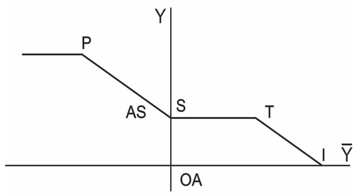
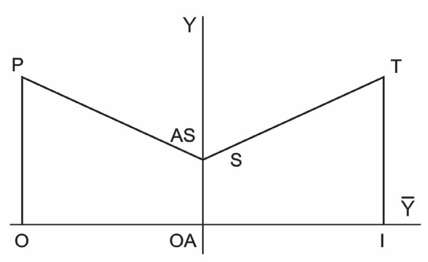
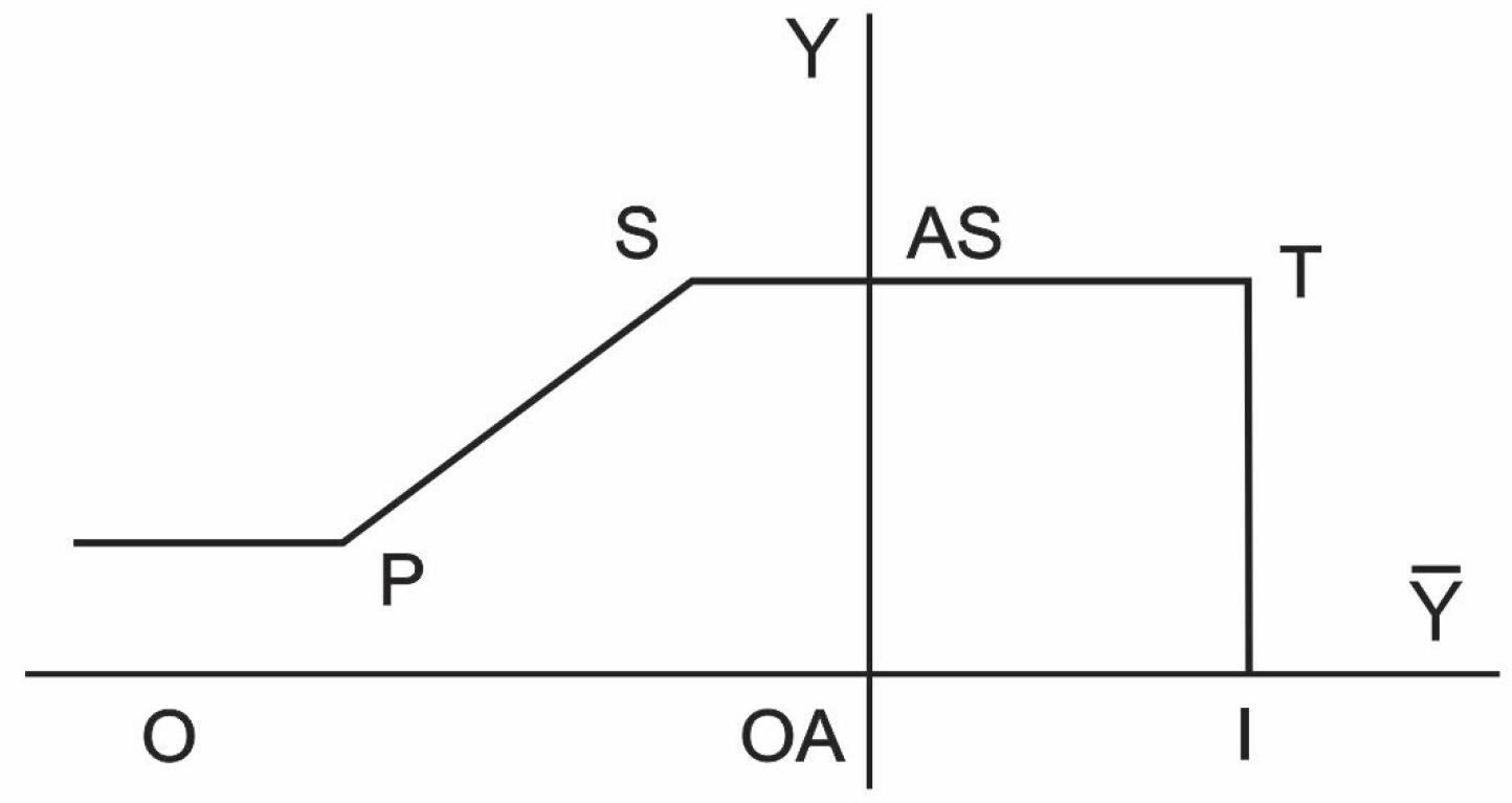
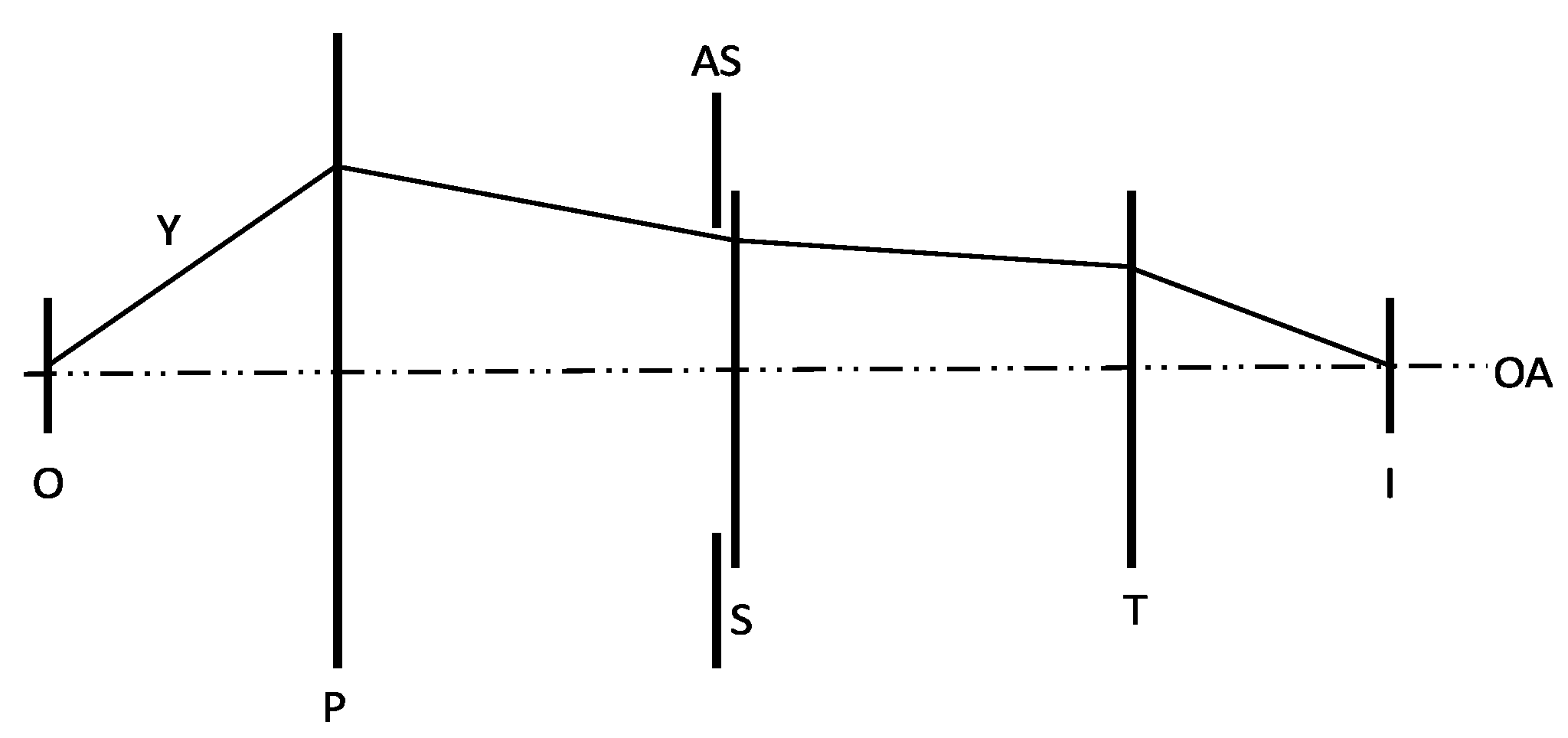
Appendix A. The Y-Ȳ Diagram

The name Y-Ȳ diagram arises from the names of two important rays in the first-order optical system design. A designer uses the first-order design when they choose a focal length (power) of a lens, knowing the object and the image distance. In the formal analysis of optical systems, the first-order design, or the analysis applicable in the paraxial region, is characterized by the possibility of replacing tangents and sines of the angles with the angles themselves. Consequently, this analysis applies only in a narrow region close to the optical axis. Furthermore, the imaging optical components such as lenses and mirrors are represented as infinite planes normal to the optical axis. Being visually oriented, we often insert a convex or concave lens as a symbol. The object and the image are also located on such a plane.
Each point R on the graph of a generalized ray on the Y-Ȳ diagram has mutually independent coordinates (Y,Ȳ). We can think of it as a vector. The only thing that connects the points on this graph is that the next point on the graph is determined by the coordinate of the previous point and the paraxial ray trace equations, namely, transfer and refraction at the surfaces with power. Object height, measured from the optical axis, has traditionally been set to be unitary, to allow scaling in the traditional (hand) ray-trace calculations. The image height is obviously dependent on the specifics of the optical system.
A marginal ray is a ray that originates at the object’s on-axis point and is directed to the edge of the aperture stop. Its height at the stop location determines the radius of the aperture stop or one-half of the side of the square aperture. It is denoted as Y; sometimes it includes a subscript that specifies the position along the optical, or z-axis, at which it is being evaluated. Every point where the marginal ray crosses the optical axis is the image location. The travel of the marginal ray through the finite conjugate optical system of Figure 1 after converting it into finite conjugates is illustrated in Figure A1.
Figure A1. Marginal ray originates at the object’s on-axis point and is directed to the edge of the aperture stop. Image location is the point where it crosses the optical axis. O denotes the object; I is the image; P, S, and T stand for the primary, the secondary, and the tertiary lens; and AS denotes the aperture stop, in this case at the secondary, that is, the negative lens. OA denotes the optical axis.
Applsci 13 08866 g0a1
Chief ray originates at the bottom object point and is directed to the center of the aperture stop, i.e., it crosses the optical axis at the stop location. An optical system has a single aperture stop, which defines its equivalent optical system, the f-number, and its throughput. The height of the chief ray at the image location determines the image height, including for the intermediate images. It is denoted as Ȳ; sometimes it includes a subscript that determines the position along the optical, or z-axis, at which it is being evaluated. Similarly, Figure A2 illustrates the travel of the chief ray through the optical system of Figure 1, working at finite conjugates.
Figure A2. Chief ray originates at the bottom object point and is directed to the center of the aperture stop. It crosses the optical axis at the stop location. O denotes the object; I is the image; P, S, and T stand for the primary, the secondary, and the tertiary lens; and AS denotes the aperture stop, in this case at the secondary, that is, the negative lens. OA denotes the optical axis.
Applsci 13 08866 g0a2
Sometimes a designer is interested in how the imaging components (lenses, mirrors) impact the primary parameters of the optical system such as object and image height, stop location, and size. For the applications where the distances along the length of the optical system are not of significance, we can present graphically how the chief and the marginal ray evolve through the optical system.
The values of chief and marginal ray are known at each point along the optical system, upon ray-trace analysis. Figure A1 and Figure A2 present these rays propagating along the z- or optical axis. In the Y-Ȳ diagram, the z-axis is facing into the page, Ȳ-axis is drawn along the horizontal axis, and Y-axis is vertical. All three axes are mutually perpendicular. The construction of these two rays represents a rigorous solution to the wave equation. This is a second-order differential equation that requires two independent (orthonormal) solutions. We can consider the trajectory of the generalized ray inside the Y- and Ȳ-diagram to be a vector (Y, Ȳ), dependent implicitly on the z- (optical) axis. A point in the Y–Ȳ plane corresponds to a z-value (a point on the axis of the optical system).
Figure A3a includes the Y-Ȳ diagram for the optical system of Figure 1, working at finite conjugates. The object is located at Point O. The size of the object is O-OA.
Figure A3. (a) The y-y-bar diagrams corresponding to Figure 1, working at finite conjugates and with magnification 1/3. (Each dashed line below the diagram indicates a unit distance. Distances are not traditionally indicated on the Y-Ȳ diagram.) A convergent optical element changes the direction of the generalized ray clockwise at P and T, while a divergent one changes the direction of the ray line in the counterclockwise direction. A small change in the diagram is illustrated in part (b): the triplet could be replaced by a single, very strong lens with a much larger diameter (aperture stop), generating the same magnification. P, S, and T stand for the primary, the secondary, and the tertiary mirror, respectively; and AS denotes the aperture stop, in this case at the secondary, that is, the negative element. OA denotes the optical axis. O and I stand for object and image. O-OA is the object size; OA-I is the image size.
Applsci 13 08866 g0a3
A generalized ray travels toward the primary P, a convergent lens whose function is to change the graph direction in a clockwise direction until the secondary lens is encountered. The secondary lens S changes the direction of the generalized ray into a counterclockwise direction because it is divergent. The tertiary lens T is convergent again, so it changes the direction of the generalized ray into the clockwise direction. When the generalized ray crosses the Ȳ-axis, at I, the height of the Y-ray is zero and the designer has found the image location. The image size is OA-I. We indicated the units below the diagram to appreciate a demagnification by a factor of 3.
As we can see in Figure A3b, the most critical system parameters, the object and the image size, and the location of the aperture stop size may remain fixed even when we change the optical elements that manipulate the generalized rays. This flexibility and clarity make the Y-Ȳ diagram an ideal first-order design tool.
Both axes measure distance in [m] or [mm], but we use a different scale on each axis. Aperture diameter is usually measured in tens of cm to a meter, while the image is captured on a focal plane array with size measured in millimeters, and each pixel in microns. The aperture is usually significantly larger than the image, so a different scale is used for both axes. The aperture size (radius, or half-side of a rectangle) is OA-AS.
A generalized ray propagates in the same direction in an isotropic medium, such as air where most optical systems operate except for the immersion subsystems. A sharp change in the direction of the graph indicates the presence of a component with power, a lens, or a mirror. A convergent optical element changes the direction of the generalized ray clockwise in the positive Y-half-plane, while a divergent one changes the direction of the ray line in the counterclockwise direction. The stronger the power of the optical elements, the greater the deviation in the line direction. Rays are represented as line segments between optical components and critical planes in the (traditional) optical system.
The function of the positive or convergent lens or a mirror is to deviate the generalized ray in a clockwise direction when a component is in the positive Y-plane. The function of a negative or divergent lens or a mirror is to deviate the generalized ray in a counterclockwise direction when the component is in the positive Y-plane. The deviations of the generalized ray are the opposite when the components are in the negative Y-plane.
We consider two special cases of ray orientation. The generalized ray is parallel to the Ȳ-axis when the chief ray Ȳ remains at the same height above the optical axis, that is, in the region of afocal ray bundles, or when the object or image is located at infinity. The generalized ray is parallel to the Y-axis when the ray bundle expands imperceptibly, that is, the slope of the marginal ray is nearly zero.

References

  1. Contreras, J.W.; Lightsey, P.A. Optical design and analysis of the James Webb Space Telescope: Optical telescope element. In Proceedings of the Novel Optical Systems Design and Optimization VII, Denver, CO, USA, 22 October 2004. [Google Scholar] [CrossRef]
  2. Marchi, A.Z.; Versluys, J.; Torralba, I.; Stockman, Y.; Kassel, R. PROBA V Multispectral Imager: Status. SPIE: Bellingham, WA, USA, 2017; p. 105640D. [Google Scholar] [CrossRef] [Green Version]
  3. Scholl, M.S. Stray light issues for background-limited far-infrared telescope operation. Opt. Eng. 1994, 33, 681–684. [Google Scholar] [CrossRef]
  4. Clermont, L.; Aballea, L. Stray light control and analysis for an off-axis three-mirror anastigmat telescope. Opt. Eng. 2021, 60, 055106. [Google Scholar] [CrossRef]
  5. Hopkins, R.E.; Hanau, R.; Osterberg, H.; Richards, O.W.; Kavanagh, A.J.; Wight, R.; Rosin, S.; Baumeister, P.; Bennett, A. Optical Design, mil-HDBK-141; Defense Supply Agency: Washington, DC, USA, 1962. [Google Scholar]
  6. Smith, W.J. Modern Lens Design; McGraw Hill: New York, NY, USA, 1992. [Google Scholar]
  7. Kingslake, R. Lens Fundamentals; Academic Press: New York, NY, USA, 1978. [Google Scholar]
  8. Welford, W.T. Aberrations of Optical Systems; Hilger: Bristol, UK, 1986. [Google Scholar]
  9. Laikin, M. Lens Design, 3rd ed.; Marcel Dekker: New York, NY, USA, 2001. [Google Scholar]
  10. Fischer, R.E.; Tadic-Galeb, B. Optical System Design; McGraw Hill: New York, NY, USA, 2000. [Google Scholar]
  11. Scholl, M.S. Design parameters for a two-mirror telescope for stray-light sensitive infrared applications. Inf. Phys. Technol. 1996, 37, 251–257. [Google Scholar] [CrossRef]
  12. Scholl, M.S. Recursive exact ray trace equations through the foci of the tilted off-axis confocal prolate spheroids. J. Mod. Opt. 1996, 43, 1583–1588. [Google Scholar] [CrossRef]
  13. Delano, E. First-order design and the y, y diagram. Appl. Opt. 1963, 2, 1251. [Google Scholar] [CrossRef]
  14. Lȏpez, F.J. The Application of the Delano Y-Y Diagram to Optical Design. Ph. D. Dissertation, University of Arizona, Tucson, AZ, USA, 1973. [Google Scholar]
  15. Zhang, K.-Y.; Yuan, X.-Y.; Cui, X.-Q. Automatic generation of optical initial configuration based on Delano diagram. Res. Astron. Astrophys. 2016, 16, 007. [Google Scholar] [CrossRef]
  16. Wilson, R.N. Reflecting Telescope Optics 1; Ch. 1, Historical Introduction; Springer: Berlin/Heidelberg, Germany, 1996; pp. 1–19. [Google Scholar]
  17. Wetherell, W.B.; Womble, D.A. All-Reflective Three Element Objective. U.S. Patent 4,240,707, 23 December 1980. [Google Scholar]
  18. Strojnik, M.; Bravo-Medina, B.; Martin, R.; Wang, Y. Ensquared energy and optical centroid efficiency in optical sensors: Part 1, Theory. Photonics 2023, 10, 254. [Google Scholar] [CrossRef]
  19. Moreno, I.; Strojnik, M. Dove prism with increased throughput for implementation in rotational shearing interferometer. Appl. Opt. 2003, 42, 4514–4521. [Google Scholar] [CrossRef] [PubMed]
  20. Scholl, M.S.; Wang, Y. Design of a high-resolution telescope for an imaging sensor to characterize a (Martian) landing-site. Opt. Eng. 1995, 34, 3222–3228. [Google Scholar] [CrossRef]
  21. Scholl, M.S. Push—Broom reconnaissance camera with time expansion for a (Martian) landing–site certification. Opt. Eng. 1997, 36, 566–573. [Google Scholar] [CrossRef]
  22. Williams, S.G.L. On-axis three-mirror anastigmat with an offset field of view. SPIE 1979, 183, 212. [Google Scholar]
  23. Cook, L.G. Three-Mirror Anastigmat Used Off-Axis in Aperture and Field. EP Patent 019447, 15 May 1980. [Google Scholar]
  24. Korsch, D. Anastigmatic three-mirror telescope. Appl. Opt. 1977, 16, 2074. [Google Scholar] [CrossRef] [PubMed] [Green Version]
  25. Noll, R.J. Reduction of diffraction of use of a Lyot stop. JOSA 1973, 63, 1399. [Google Scholar] [CrossRef]
  26. Wang, Y.; Vaughan, A.H. Simplified solution of diffraction from a Lyot system. Appl. Opt. 1988, 27, 27. [Google Scholar] [CrossRef] [PubMed]
  27. Scholl, M.S. Using the y, y-bar diagram to control stray light noise in IR systems. Inf. Phys. Technol. 1997, 38, 25–30. [Google Scholar] [CrossRef]
  28. Wang, Y. Dichroic Beam Splitter and Related Apparatus and Methods. U.S. Patent 7,616,378, 10 November 2009. [Google Scholar]
  29. Offner, A. New concepts in projection mask aligners. Opt. Eng. 1975, 14, 130. [Google Scholar] [CrossRef]
  30. Strojnik, M.; Kirk, M.S. Telescopes. In Fundamentals and Basic Optical Instruments; Malacara, D., Thompson, B., Eds.; CRC Press: New York, NY, USA, 2018; pp. 325–375. [Google Scholar]
  31. Hallam, K.L.; Howell, B.J.; Wilson, M.E. Wide-Angle Flat Field Telescope. U.S. Patent 4,598,981, 8 July 1986. [Google Scholar]
  32. Wang, Y. Compact, Folded Wide-Angle Large Reflective Unobscured Optical System. U.S. Patent 5,379,157, 3 January 1995. [Google Scholar]
  33. Korsch, D. Near-Anastigmatic Compact Collimator. U.S. Patent 4,632,521, 30 December 1986. [Google Scholar]
  34. Falaggis, K.; Rolland, J.; Duerr, F.; Sohn, A. Freeform optics: Introduction. Opt. Express 2022, 30, 6450. [Google Scholar] [CrossRef] [PubMed]
  35. Garrard, K.; Bruegge, T.; Hoffman, J.; Dow, T.; Sohn, A. Design tools for freeform optics. SPIE 2005, 5874, 58740A. [Google Scholar] [CrossRef]
  36. Johnson, T.P. Optical System Design and Distortion Control of Wide Field of View, All-Reflective Imagers. Ph.D. Dissertation, University of Arizona, Tucson, AZ, USA, 2019. [Google Scholar]
Figure 1. The optical layout of the classical Cooke triplet. The optical stop is located at the second or the negative, lens. O denotes the object, in this case, located at infinity; I is image; P, S, and T stand for the primary, the secondary, and the tertiary lens; and AS denotes the aperture stop, in this case at the secondary, that is, the negative lens. OA denotes the optical axis.
Applsci 13 08866 g001
Figure 2. The Y-Ȳ diagram of the classical Cooke triplet, with the optical stop located at the second, or the negative, lens. The letters P, S, and T stand for the primary, the secondary, and the tertiary imaging component, respectively; and AS denotes the aperture stop, in this case at the secondary, that is, the negative component. OA denotes the optical axis while I stands for image. OA-I is the image height.
Applsci 13 08866 g002
Figure 3. Afocal Mersenne designs: (a) a classical rotationally symmetric system, where the secondary mirror blocks some of the incoming beam bundle, upon introducing a central obscuration; (b) an off-axis system is achieved upon slicing off the bottom half of the primary mirror, and recentering the secondary mirror. P and S stand for the primary and the secondary; and AS denotes the aperture stop, in this case at the secondary, that is, the negative mirror. OA denotes the optical axis.
Applsci 13 08866 g003
Figure 4. The Y-Ȳ diagram of the afocal Mersenne design, with the optical stop located at the second, or the negative, lens. The letters P and S stand for the primary and the secondary mirror; and AS denotes the aperture stop, in this case, at the secondary, that is the negative mirror. This figure is identical to the Y-Ȳ diagram in Figure 2, featuring the Y-Ȳ diagram of the classical Cooke triplet, without the tertiary mirror and its image.
Applsci 13 08866 g004
Figure 5. The RT optical design is featured in US Patent 4,240,707 [17], here slightly modified. Item 36 is the focal plane. The incoming beam forms an angle of about 22° with respect to the optical axis (Item 4). Item 40 is the internal baffle, which is used to block the beam, from striking the third mirror (Item 33). This baffle prevents light from scattering directly onto the focal plane. The coordinate system in the object space is defined around the beam (z-axis) axis. It is re-established in the image space.
Applsci 13 08866 g005
Figure 6. When the optical stop in the classical Cooke triplet is moved from the second, the negative lens, to the first, the positive lens, these two lenses form an (intermediate) image between lens 2 and lens 3. The new system in fact forms two images. O denotes an object, in this case, located at infinity; I is image and II is the intermediary image; P, S, and T stand for the primary, the secondary, and the tertiary element; and AS denotes the aperture stop, in this case at the primary, that is, at the first positive lens. OA denotes the optical axis.
Applsci 13 08866 g006
Figure 7. The equivalent Y-Ȳ diagram for the design shown in Figure 6. Points P (primary) and S (secondary) together with an intermediate image at point II form a Cassegrain objective. O denotes an object, in this case, located at infinity; I is image; P, S, and T stand for the primary, the secondary, and the tertiary element; AS denotes the aperture stop, in this case at the primary, that is the positive component. OA denotes the optical axis. I denotes the image location, II indicates the intermediary image. The final image size is OA-I; the intermediate image size is OA-II.
Applsci 13 08866 g007
Figure 8. An excellent TMA optical layout is found in Ref. [23] (European Patent EP 0019447). The optical stop is located at element 1 (Item 12); the intermediate focal point (Item 18) also hosts a field stop; and the Lyot stop is Item 22.
Applsci 13 08866 g008
Figure 9. The US Patent 7,616,378 [28] where a concept of a phase plate on a beam splitter (Item 111) is disclosed. A phase plate is inserted into an RT system to remove newly introduced aberrations in the transmission channel, Item 121A. The phase plate is placed on the transmission (second) surface of the beam splitter.
Applsci 13 08866 g009
Figure 10. Offner relay system is a finite one-to-one conjugate Cooke triplet, with the optical stop located at the secondary, a negative lens. The design is object- and image-symmetric with respect to the optical stop. O denotes object, in this case, located at the distance equal to twice the focal distance of component 1; I is image, in this case, located at the distance equal to twice the focal distance of component 3; P, S, and T stand for the primary, the secondary, and the tertiary lens; and AS denotes the aperture stop, in this case at the secondary, that is the negative lens. OA denotes the optical axis.
Applsci 13 08866 g010
Figure 11. Y-Ȳ diagram of the Offner relay, presented in Figure 10, is clearly a one-to-one, finite conjugate system, symmetric with respect to the optical stop. O denotes object, in this case, located at a distance equal to twice the focal distance of the primary component; I is image, located at a distance equal to twice the focal distance of the tertiary (equal to that of the primary component); P, S, and T stand for the primary, the secondary, and the tertiary component; and AS denotes the aperture stop, in this case at the secondary, that is, at the negative mirror. OA denotes the optical axis. The object size O-OA is equal to the image size OA-I.
Applsci 13 08866 g011
Figure 12. Offner relay system is a concentric (Mirror 1 plus Mirror 3 and Mirror 2) system. The new system now is, literally, top- and bottom-symmetric with respect to the optical axis. The curved plane parallel plate CP is a weak lens in front of the complete system, and physically behind the secondary mirror. It corrects the fifth-order spherical aberration. O denotes object; I is image; P, S, and T stand for the primary, the secondary, and the tertiary mirror; and AS denotes the aperture stop, in this case, at the secondary, that is, a negative mirror. OA denotes the optical axis.
Applsci 13 08866 g012
Figure 13. The WALRUS design may be considered an optical layout of an inverse-telephoto derivative, having the optical stop located between the second and the third lens. O denotes object, in this case, located at infinity; I is the image location; P, S, and T stand for the primary, the secondary, and the tertiary lens; and AS denotes the aperture stop, in this case between the secondary and the tertiary lens. OA denotes the optical axis.
Applsci 13 08866 g013
Figure 14. The Y-Ȳ diagram of the WALRUS system of Figure 13. O denotes the object, in this case, located at infinity; I is the image; P, S, and T stand for the primary, the secondary, and the tertiary component; and AS denotes the aperture stop, in this case, it is located between the secondary and the tertiary element. OA denotes the optical axis. OA-I is the image size.
Applsci 13 08866 g014
Figure 15. WALRUS design from the U.S. Patent 4,598,981 [31]. Item 34 is the optical stop, Line B2 and the optical axis (Item 18) form an offset angle of about 45°.
Applsci 13 08866 g015
Figure 16. Another WALRUS design from the U.S. Patent 5,379,157 [32]. The design presented in Figure 15 has been folded at the optical stop (Item 24). A distortion corrector (Item 32) is placed near the focal plane (Item 30).
Applsci 13 08866 g016
Figure 17. The Korsch triplet, from the U.S. Patent 4,632,521 [33], with annotations. Item 16 is a large, positive primary mirror; Item 20 is a smaller positive secondary mirror. Secondary mirror is followed by a relatively small negative tertiary mirror (Item 26). Item 12 is optical axis. Item 18 indicates the beam angular subtense for the points at the bottom (chief ray), the center (marginal ray), and from the top of the object in infinity (the auxiliary chief ray). The final image is located at F. The location of the intermediary image is at the overlap of all three beams (Items 18) right above the optical axis, indicated with a blue line segment and denoted by II. The intermediate focal plane is located between the primary and secondary mirrors in this design.
Applsci 13 08866 g017
Disclaimer/Publisher’s Note: The statements, opinions and data contained in all publications are solely those of the individual author(s) and contributor(s) and not of MDPI and/or the editor(s). MDPI and/or the editor(s) disclaim responsibility for any injury to people or property resulting from any ideas, methods, instructions or products referred to in the content.

