1. Introduction
Assuring the efficacy and safety of radiation treatments has always been of paramount importance in the clinical management of radiotherapy patients. In a technical manual published in 2008 entitled “Radiotherapy risk profile”, the World Health Organization reviewed the security measures in radiotherapy departments all around the world. The causes of adverse events are investigated through the analysis of 3125 errors and 4616 quasi-errors, finding that the most frequently contributing factors are linked to dosimetry-related errors [
1]. The authors specify, therefore, that the introduction of a comprehensive delivery quality assurance (DQA) program in radiotherapy practice is mandatory to reduce the number and/or severity of incidents. In addition, in December 2013, the European Union addressed the issue by publishing the Council Directive 2013/59/Euratom, laying down uniform basic safety standards for the protection of individuals against the dangers arising from exposure to ionizing radiation. In particular, in the framework of the chapter on Medical Exposures, the document cites, “
For all medical exposure of patients for radiotherapeutic purposes, exposures of target volumes shall be […] appropriately verified”. This takes on particular importance in the light of the latest technological improvements in the radiotherapy field, which can potentially act as new sources of error. In fact, radiation therapy has greatly expanded in complexity, but resources have been inadequate to handle this ever-increasing complexity [
2].
Stereotactic radiosurgery (SRS) is a typical example of an advanced radiotherapy technique becoming an essential tool in the management of a growing number of malignant and benign conditions. The accuracy of dose administration in such a technique, delivering precisely-targeted high-dose sessions, is of paramount importance to guarantee both the clinical outcome and the absence of severe toxicities. As stated by the report of AAPM Task Group No. 135, a mistaken delivered dose or beam displacement errors may result “
in inaccurate estimates of accumulated dose as well as inaccurate estimates of the steepness and location of the high dose gradient regions that may be designed to protect adjacent critical structures and organs at risk” [
3]. A comprehensive QA program is therefore all the more important, but the challenges of such a program are still exacerbated by a lack of efficient and accurate equipment [
4].
DQA tests are generally performed by means of ionization chambers, solid-state point detectors, or radiochromic films [
4,
5]. Recently, 2D and 3D detector arrays are increasingly being used in SRS, even just for specific tasks like planar dose mapping [
6,
7]. Despite this, their use in clinical practice is still hindered by drawbacks and limitations. While point measurements are inappropriate for achieving full information about the intended dose distribution, radiochromic films need special handling care and are time-consuming tools. A device combining a contiguous high resolution and a bidimensional active area capable of performing both periodic DQA tests and accurate dose map comparisons is still needed, particularly when it comes to robotic radiosurgery.
In spring 2021, a new high-resolution detector was released for clinical use by IBA (myQA® SRS, IBA Dosimetry GmbH, Schwarzenbruck, Germany) for SRS and stereotactic body radiotherapy (SBRT) QA of treatments delivered with conventional linear accelerators (linac). Systems such as Varian Ethos™/Halcyon™ and CyberKnife® MLC, Iris, or Cones are also supported, but validation testing for the CyberKnife is still work in progress. myQA® SRS is therefore not available for sale for these systems. On the other hand, its innovative resolution and dosimetry properties seem very promising, and for this reason, we decided in this study to evaluate the myQA® SRS detector in the context of intracranial SRS administered using CyberKnife® (Accuray, Sunnyvale, CA, USA) robotic linac. Delivering very high doses through small non-isocentric non-coplanar radiation fields, the CyberKnife® treatments are a compendium of many critical issues in the dosimetry of radiosurgery plans. The small sensitive volume of the sensors and the wide energy range make myQA® SRS a potentially effective tool in dealing with these issues.
The DQA workflow of this study was designed to investigate the detector′s performance in two main clinical fields of application:
Periodic machine QA, by replicating the main tests characterizing a CyberKnife QA program.
Verification of patient-specific treatment plans, particularly with regard to the CyberKnife’s multiple incident beam directions, which effectively precludes the use of the provided gantry sensor for automated gantry angle correction.
The detector′s behavior in terms of dose rate and beam angular dependences was also investigated, which was especially useful for verifying patient-specific plans.
2. Materials and Methods
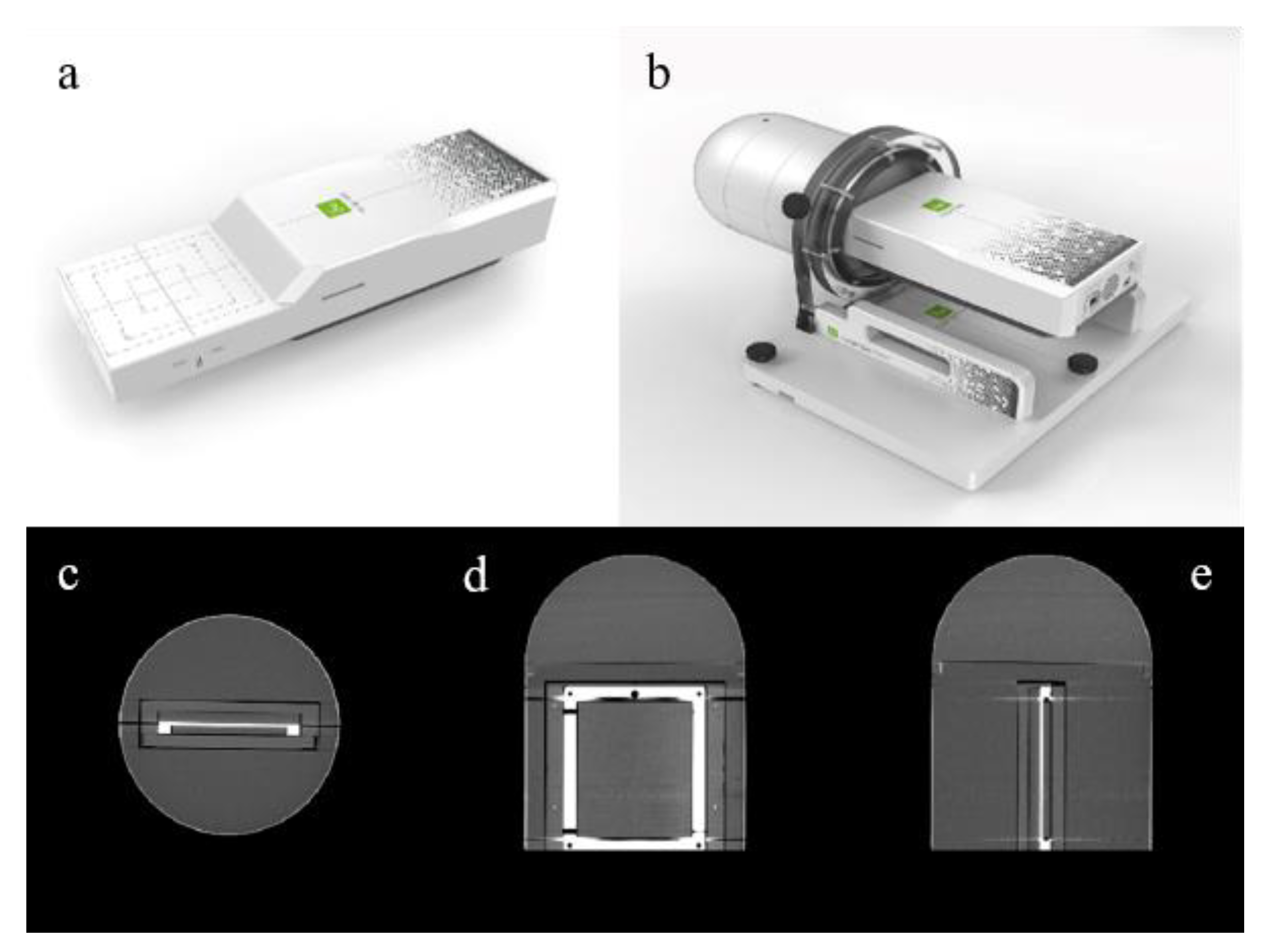
A prototype of myQA
® SRS detector was provided to the authors′ Institute in October 2021. The active detector area is composed of a 12 × 14 cm
2 CMOS solid-state sensor matrix, with 0.4 mm resolution. Also, no interpolation of measurement results is necessary since the pixels are contiguous and there is no spacing between them. These features can greatly improve the detector’s ability to effectively identify treatment dosimetric problems even when measuring the small dose distributions typical of SRS, as for example in the case of trigeminal neuralgia and other functional treatments (characterized by very high doses delivered to a small brain area of 4 to 5 mm in diameter). The thickness of the active area is 750 µm and the detector array is embedded in an ABS insert (electron density relative to water = 1.030) at a depth of 19.3 mm from the upper face. The array can be allocated in a cylindrical ABS phantom, topped by a hemispheric cap for non-coplanar arc delivery. Additional tools include dedicated inserts for film and for small field dosimetry chambers. The link between the detector system and the PC equipped with the myQA
® Platform acquisition software is provided by an RJ-45 Ethernet cable. An image of myQA
® SRS detector and cylindrical phantom can be seen in
Figure 1.
The machine DQA protocol chosen to test the device performance followed the authors′ Institute practice for periodic verification of beam parameters such as output factors, off-axis ratios, delivered dose linearity and reproducibility, and patient plan verification. The institutional protocol is based upon national and international published guidelines [
3,
8,
9,
10]. The actual size of the Iris
TM variable aperture collimator was verified as recommended by the manufacturer and as part of the authors’ standard QA program. Finally, two final dosimetry checks were performed to fully characterize the device, namely the detector′s reading dependence on photon dose rate and radiation beam angle of incidence.
2.1. Phantom Preparation and CT Acquisition
The first step of the workflow was the preparation of the myQA
® SRS system for CT acquisition. The CyberKnife® uses real-time tracking of at least three fiducial seeds, usually embedded in the measurement phantom, to determine the detector′s position for alignment with the machine coordinate frame during patient-specific QA delivery. A full description of the Fiducial Tracking method can be found elsewhere [
11,
12]. We therefore distributed lead pellets of about 1 mm in diameter onto the phantom surface. These markers were chosen to provide enough X-ray contrast to be individuated by the image guidance system while at the same time not causing star pattern artifacts on the CT scan.
The sensor array inserted in the cylindrical phantom was imaged using a Revolution GSI CT scanner (General Electric, Chicago, IL, USA) to determine the planar doses calculated by the treatment planning system (TPS) at the detector′s position. The acquisition protocol was identical to the one used at the authors’ Institute for clinical CyberKnife® planning: 120 kV, 400 mAs, 1.25 mm slice thickness, and 30% ASIR iterative reconstruction. The acquired CT images were imported into the TPS and the phantom boundary (named Skin) and the CMOS device (named PTV) were contoured. The electronic components were also identified for verification purposes, in order to ensure they did not receive any significant dose.
2.2. Detector′s Initialization Pipeline
According to the manufacturer′s instructions, a precise pipeline was followed in order to correctly set up the system and perform accurate exposure measurements.
2.2.1. Detector Warm Up and Noise Compensation
The first step of the dose measurement chain concerned the detector warming up under reference conditions. To this end, myQA® SRS detector was positioned on the patient couch inside its cylindrical phantom. An ad-hoc pre-irradiation plan was subsequently delivered to properly warm-up the entire CMOS matrix by administering a minimum dose of 120 cGy to each sensor.
The residual electronic noise was compensated with a 60 sec background acquisition prior to performing further dose measurements. Warm-up and noise compensation procedures for the detector were performed at the start of each measurement session for both machine QA and patient-specific plan verification.
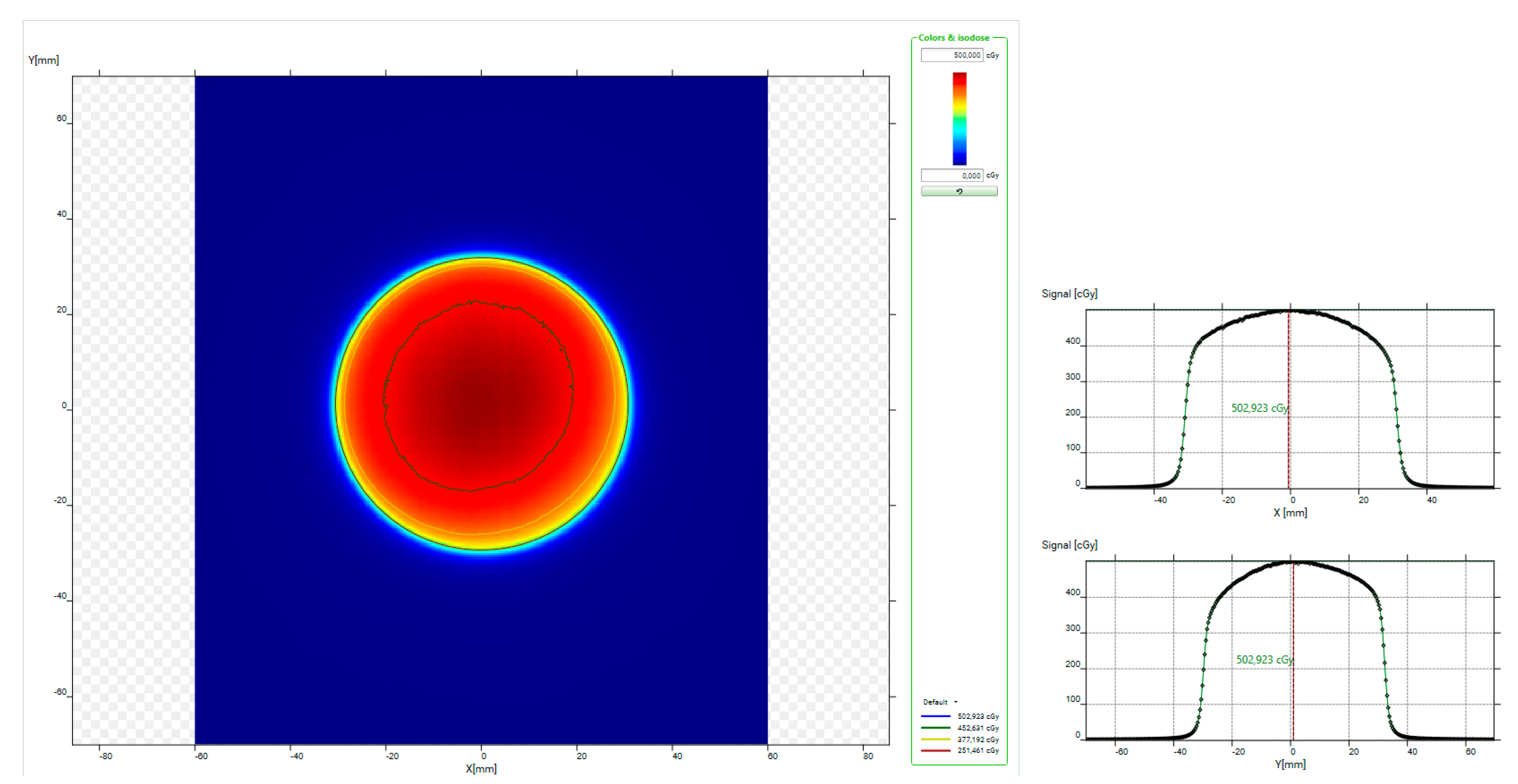
2.2.2. Absolute Dose Calibration
According to the indications of the manufacturer, the dose calibration for myQA® detector is dose rate dependent. The nominal dose rate of the CyberKnife® is 1000 MU/min, and it does not significantly vary during treatments. The dose calibration was performed at a source-to-detector distance of 800 mm, useful for many machine and intracranial patient-specific QA tests. To this aim, an ad-hoc isocentric plan was optimized using the CyberKnife® TPS, in order to deliver 500 cGy to myQA® SRS matrix central pixels (4 × 4 pixels) by employing the 60 mm fixed collimator. myQA® Platform software estimates a cGy/counts correction factor from the measurement data, to be applied to all subsequent experiments. The dose output of the sensors outside the central area is automatically derived by applying a conversion matrix preloaded in the software and based on factory provided response values relative to the central pixels. The detector′s calibration procedure was performed at the beginning of the study and every so often as a constancy check.
2.3. Periodic Machine DQA Tests
The machine DQA tests described in the following paragraphs were always performed according to reference set-up conditions, carefully checked for both the delivery and acquisition systems:
Delivery beam orthogonal to the detector surface;
800 mm source-to-axis-distance (SAD);
myQA® SRS detector accurately levelled on the treatment couch.
The detector was always used free of its cylindrical phantom. For comparison purposes, the authors chose a battery of tests that reproduced as closely as possible those already in use at their Institute.
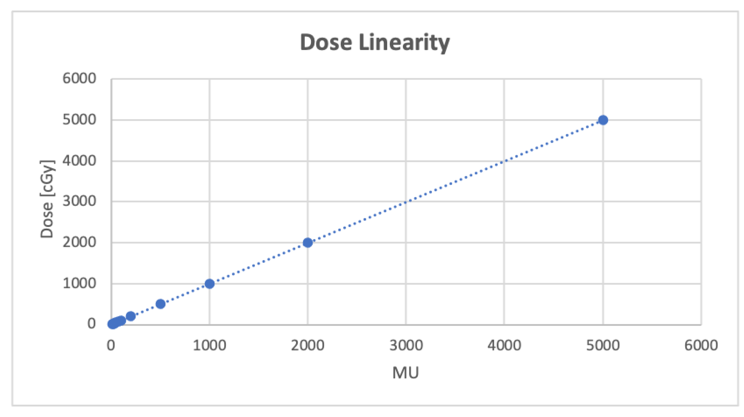
2.3.1. Dose Linearity and Reproducibility Test
The CyberKnife linac is calibrated to deliver 1 cGy/MU at a depth of 15 mm in water (800 mm SAD) using the 60 mm reference collimator. This value is verified through periodic checks. In order to evaluate the linearity of myQA® SRS dose response, increasing MU values were delivered from a minimum value of 10 up to a maximum of 5000 (steps: 10, 20, 30, 40, 50, 70, 100, 200, 500, 1000, 2000, 5000) with a 60 mm fixed collimator to the detector array. The signal in the 3 × 3 pixels central area was recorded and the MU–Dose scatter plot was fitted to estimate the squared correlation coefficient.
For the dose reproducibility test, 100 MU was delivered to the detector at five different times, and the 3 × 3 central pixels signal was recorded and analyzed.
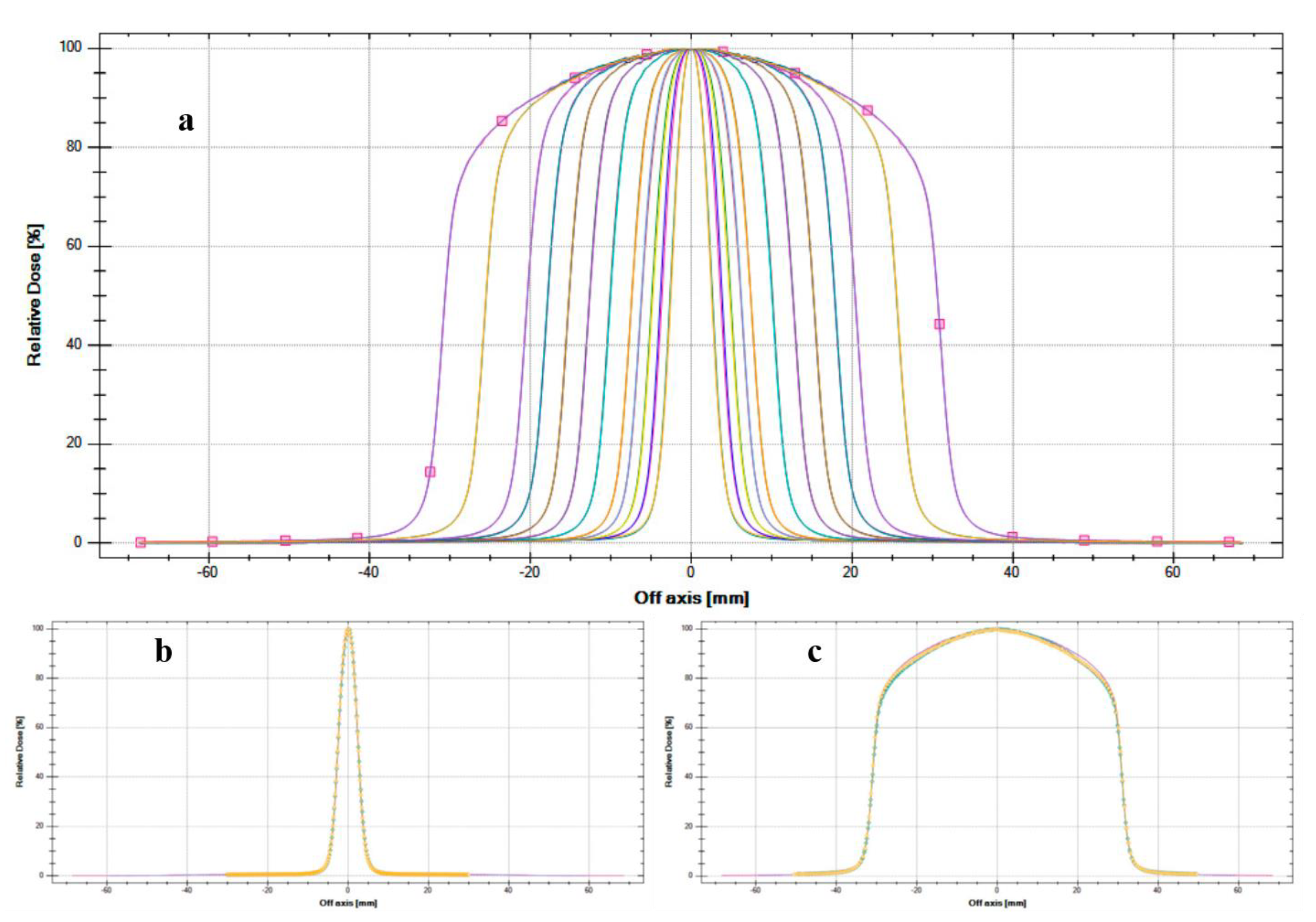
2.3.2. Beam Profiles and Off-Axis Ratios
In order to assess the detector performance for beam profiles analysis and Off-Axis Ratio (OAR) estimation, acquisitions with the myQA® SRS detector were performed for all the 12 fixed circular cones (5, 7.5, 10, 12.5, 15, 20, 25, 30, 35, 40, 50, 60 mm in diameter) mounted by the CyberKnife®. As a consequence of the detector′s assembly, the fields were measured at a depth of 19.3 mm in ABS. This allowed a reasonably precise comparison with our periodic checks at a depth of 1.5 mm in water, considering the range of the depth dose maximum plateau for the 6 MV beam of our CyberKnife® unit.
Profile extraction along the x and y axis and subsequent data analysis were performed with myQA® Accept (IBA) software. The parameters considered were field width, flatness, symmetry, and penumbra.
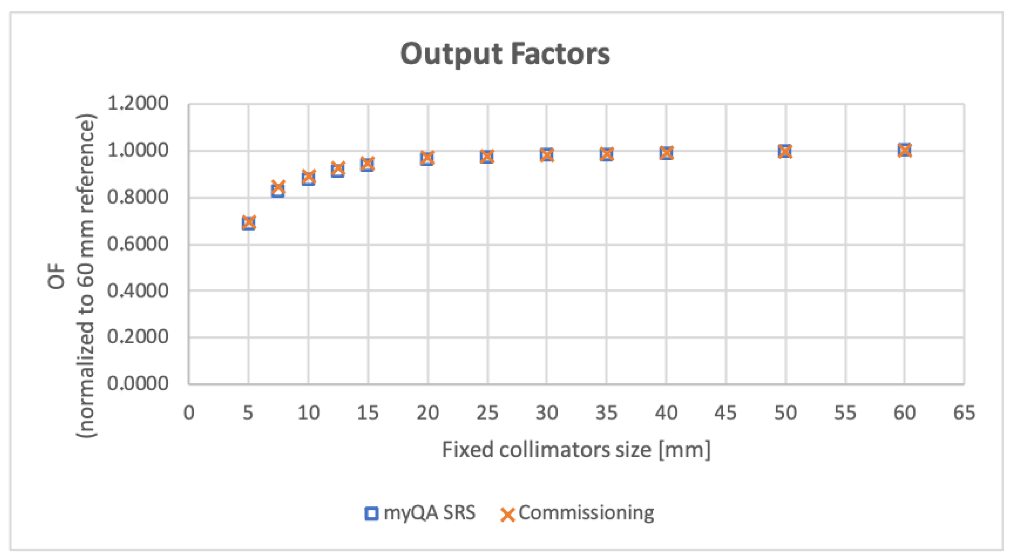
2.3.3. Output Factors
Output factors (OF) were measured for a SAD of 800 mm, corresponding for CyberKnife® to the radiation source-to-lesion distance used to treat intracranial targets, which constitute the main bulk of the authors′ Institute irradiation sites. Acquisitions were performed for all the 12 fixed collimators and the resulting values were normalized to the 60 mm reference cone reading in the same measurement condition. Signal mean value was estimated by placing a 3 × 3 pixels region of interest (ROI) in the matrix center. For collimator cones smaller or equal to 10 mm in diameter, considering the pixel linear size of 0.4 mm, a ROI of 2 × 2 pixels was employed. No Monte Carlo or other correction factors were applied to the final OF values. The authors’ Institute’s myQA® SRS OF values were compared to those used in clinical practice.
2.3.4. Variable Aperture Iris™ Collimator Fields Size
The CyberKnife® used in this study is equipped with a secondary collimator named Iris™ with a computer-adjustable aperture. The Iris™ collimator mimics the same 12 openings as the fixed collimators thanks to two offset overlaid tungsten segments that allow a quick adjustment of the aperture. The segments are hexagonal shaped with an offset providing a 12-sided opening. All segments are driven by a single motor and the manufacturer suggests performing a monthly field size check to evaluate reproducibility.
At the authors′ Institute, this is performed with the manufacturer-provided Iris QA Tool, designed to offer a film-based alternative to the use of a water phantom. Before running periodic checks, a baseline measurement was carried out at the time of the collimator installation to determine the reference field sizes by averaging the corresponding values from 4 film shots for each Iris aperture and for the 15 mm fixed collimator used as reference. The Iris QA software determines an optical density (OD) threshold value corresponding to a computed field size for the 15 mm cone that matches its nominal size of 15 mm. This threshold is then used to extract the field size from irradiated films, exploiting two different approaches:
- (a)
an Equivalent Diameter (ED) calculation:
- (b)
a Profile Diameter (PD) calculation where the field size is determined based on the average of 12 profiles taken at equally spaced angles around the centroid of the thresholded image.
The baseline calculations at the time of the collimator installation for all field sizes over the 4 irradiated films gave a range of variability of 0.4 mm. In the authors’ Institute, all Iris constancy QA checks are performed by averaging the ED and PD calculations from two film shots for a given Iris aperture. The result is then compared to the baseline measurement.
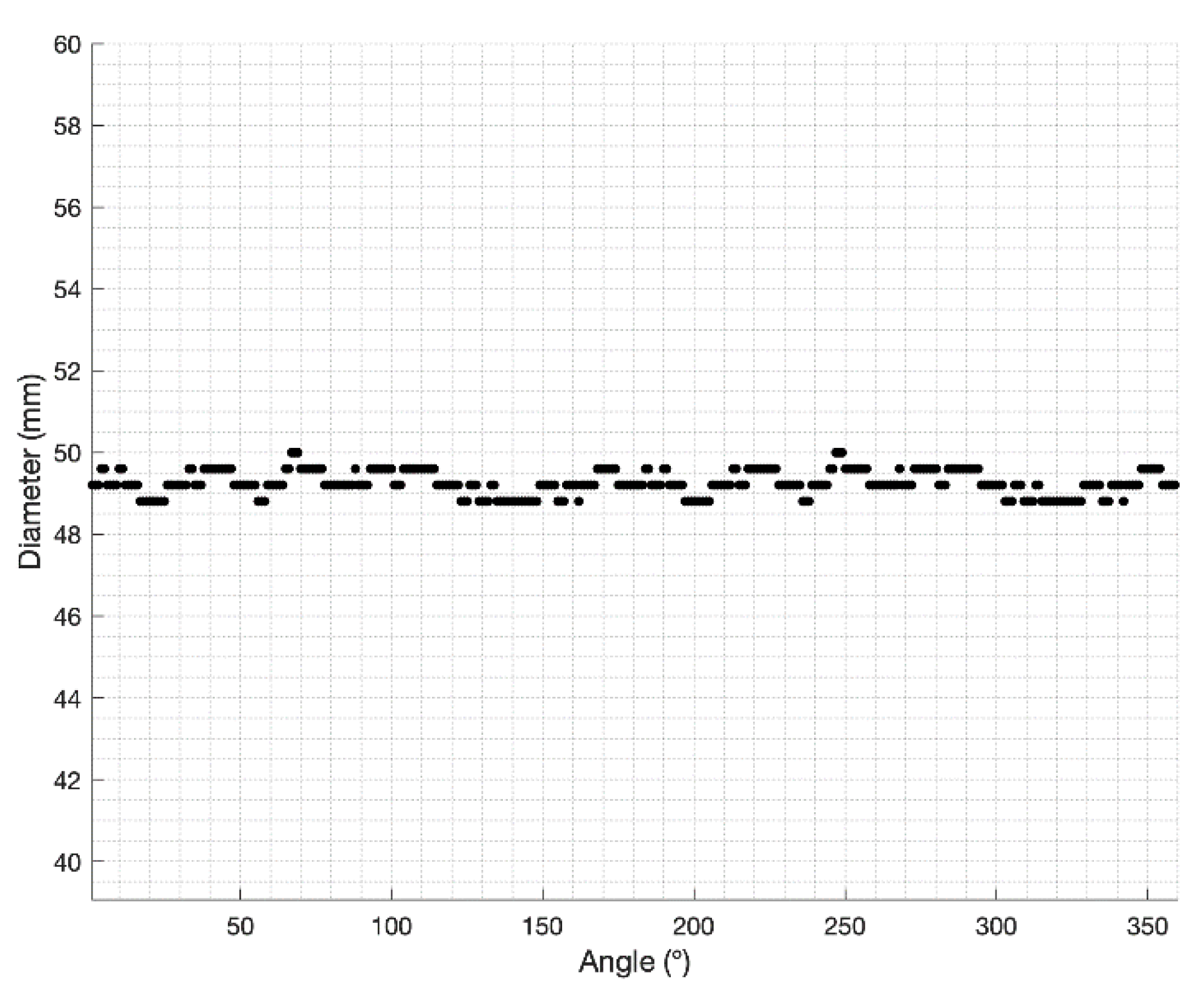
With myQA
® SRS the estimate of the diameter was carried out by orthogonally delivering onto the detector array the Iris™ beams corresponding to the 12 apertures (SAD = 800 mm). The data collected for each aperture were analyzed using a homemade MATLAB (
https://it.mathworks.com/products/matlab.html) (accessed on 4 April 2022) script through the following steps:
Identification of the center of the dose distribution by searching the maximum signal of the image;
Radial sampling of the distribution with an angular step = 1° in a range between 0 and 360°;
Calculation of the Full Width at Half Maximum (FWHM) for each radial profile (
Figure 2);
Measure of the field size obtained as average of the FWHMs.
The beam delivery and analysis procedures were repeated 3 times for each field size.
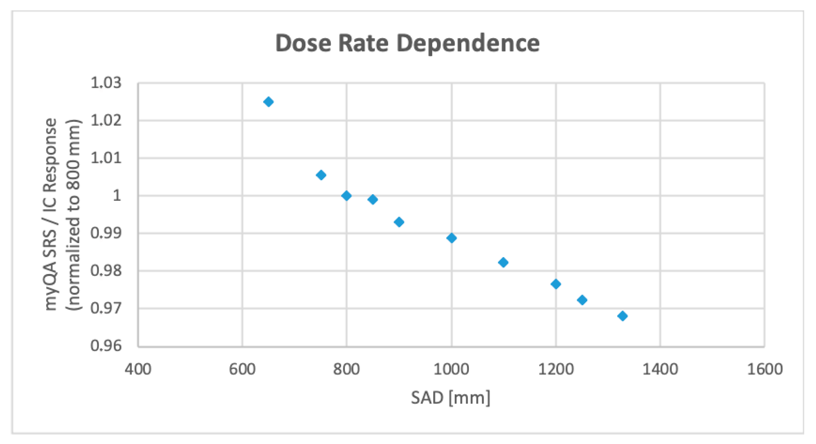
2.4. Dose Rate Dependence
To the best of our knowledge, no specific data are available in the literature about exposure dose rate dependence for CMOS at the energies typical of photon radiotherapy. We used the same experimental setup that we designed for the same purpose in a previous study, i.e., measuring the ratio between the detector response and a Farmer ion chamber (FC65-G, IBA) response under the same irradiation conditions, assuming the ionization chamber is insensitive to dose rate variations [
4,
13].
In this study, the incident dose rate was varied by altering the SAD from 650 mm (the distance used by the CyberKnife® to treat trigeminal targets located in critical positions with respect to the brainstem) to 1200 mm (the distance chosen to include body target treatments). Irradiation was performed with the 60 mm reference collimator and the myQA® SRS 3 × 3 pixels central area response was selected for comparison to the chamber reading.
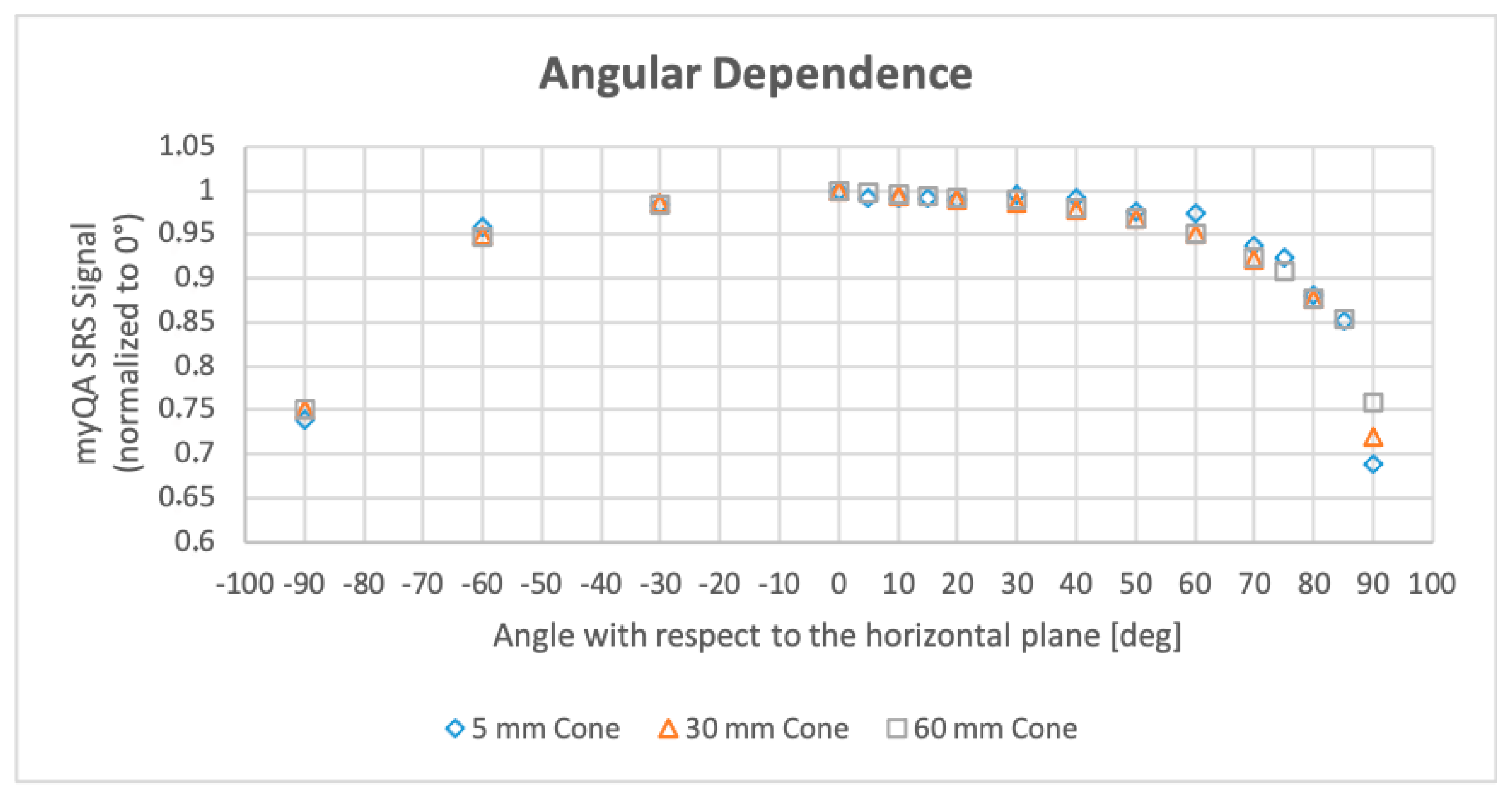
2.5. Beam Angular Dependence
Since no specific detector reading correction is available as a function of the angle of incidence of the CyberKnife® beams, a preliminary study was performed to evaluate angular dependence of measurements before patient QA verification.
The experimental setup took advantage of the possibility of the myQA® SRS phantom to rotate around its own axis at predefined angles. The CyberKnife® beam was kept orthogonal to the treatment couch (horizontal plane), while the detector and phantom were rotated clockwise from 0° (horizontal plane) to 90° (vertical plane, parallel to the beam axis) with 10 degree steps. Measurements were repeated, also rotating counterclockwise in the range 0°−90° with 30° steps for verification of the symmetry of the system. Irradiation was performed with the 60 mm, 30 mm, and 5 mm fixed collimators (800 mm SAD) and the signal over the 3 × 3 central pixels (2 × 2 pixels for 5 mm aperture) was normalized with respect to the 0° reading.
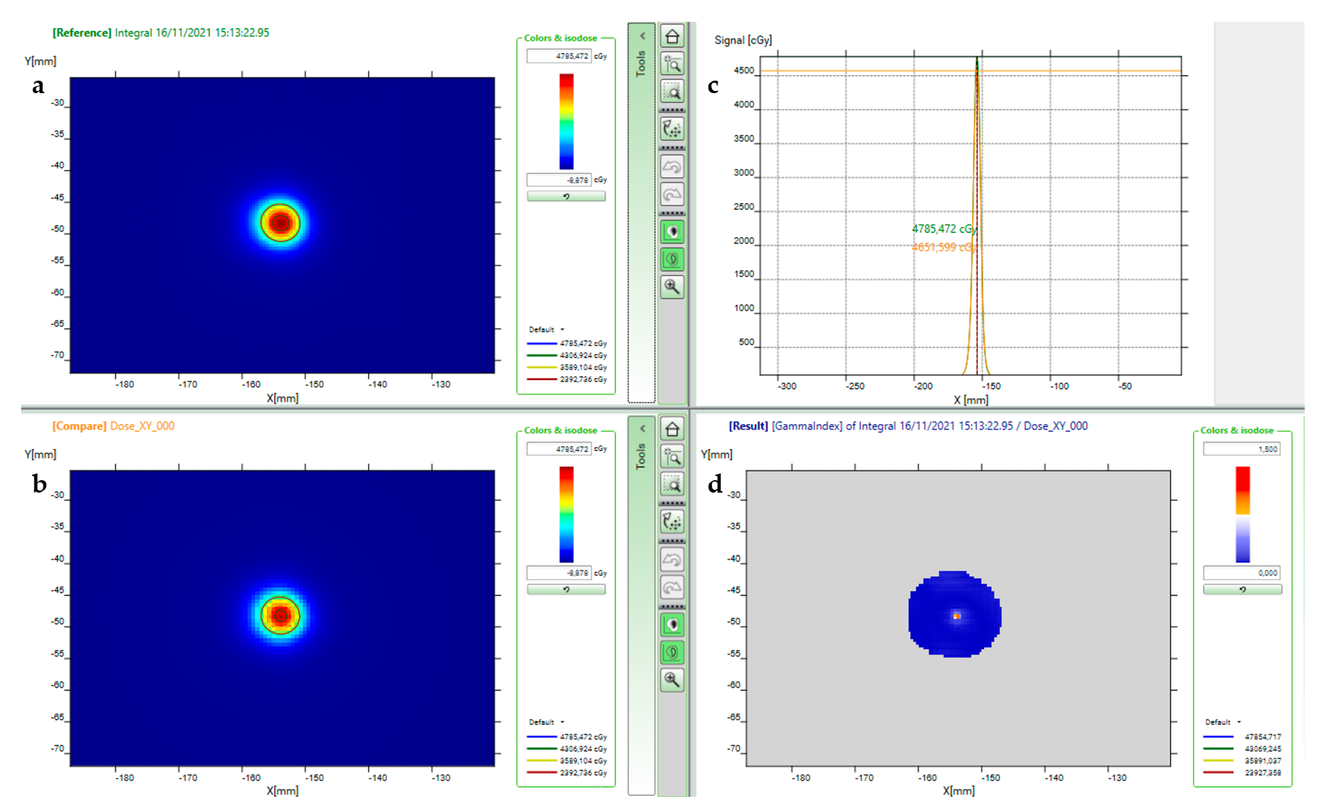
2.6. Patient Plan QA Verification
Patient treatments clinically delivered with CyberKnife® were retrospectively checked by administering the same beam geometry and MUs to the myQA SRS® phantom. All patients gave written informed consent, which included anonymized data usage for research purposes.
As in our standard of practice with pre-treatment QA performed with other detectors, treatment plans were rigidly registered to the myQA
® SRS phantom so that patient planning target volume (PTV) and array center-of-mass overlapped. When necessary, further translational adjustments were manually applied in order to satisfy fiducial marker pattern requirements with respect to the CyberKnife image guidance system (at least 3 fiducials contemporarily visible on the imaging X-ray projections). The planar dose (Ray Tracing algorithm) corresponding to the CMOS device was then exported from the TPS and compared to myQA SRS reading. As suggested by AAPM Task Group No. 218 recommendations [
14], a dose calibration verification was performed before each measurement session to factor in the daily variation of linac output.
The agreement between measured and TPS dose distributions was evaluated using myQA
® Platform software to calculate the Gamma Index with a local dose-difference of 3% and a distance-to-agreement of 1 mm criteria [
15].
Plans for various intracranial target sizes (PTV volumes ranging from a few to several cubic centimeters) and locations were investigated to evaluate the detector′s performance on a more comprehensive sample of treatment doses (from 5 to 75 Gy prescription dose) and beam ballistics.
Patient Plan QA Verification after Beam Pruning
Taking into account the device’s angular response, beams above a threshold angle were removed, and the resulting QA plan was also calculated and delivered. The same Gamma Index criteria as above were employed for evaluation purposes.
4. Discussion
The peculiarities of radiosurgery delivery pose a whole new set of challenges for DQA programs [
3]. To date, an ultimate device capable of performing accurate and efficient periodic dosimetry verification and pre-treatment patient-specific QA in the field of SRS, in particular when delivered with robotic systems, is lacking. High-resolution solid-state detectors providing point measurements are inappropriate for achieving full information both in the target area and in the steep dose gradient regions, which also deserve verification. Although enabling highly-resolved bidimensional measurements, radiochromic films (Gafchromic™, Ashland ISP Inc., Kentucky, KY, USA) need special handling care, are time-consuming tools, and may require dose scaling in order to avoid signal saturation [
23]. To overcome these limitations, in recent years, there has been great interest in the development of 2D and 3D detectors.
An example is MapCHECK
® (SunNuclear, Melbourne, Australia), a 7.7 cm × 7.7 cm 2D array composed of 1013 diodes with a diagonal center-to-center separation of 2.47 mm. Each diode has 0.48 mm × 0.48 mm planar dimensions. The MapCHECK was recently evaluated for the patient-specific verification of thirty-three intracranial CyberKnife® plans [
7]. The equipment resulted in being an option for patient-specific QA, obtaining 3%/1 mm Gamma Index passing rates above 90%. Despite non-continuous resolution, the device was also employed for trigeminal neuralgia treatment verification, obtaining high Gamma Index passing rates. The calibration factors used in this study were manufacturer provided and have been analyzed in another paper along with dose rate and angular corrections [
24]. The described array and dose calibration procedures seemed to be quite hard-working and error-prone. No tests were reported by the authors for machine DQA.
The OCTAVIUS
® 1000 SRS (PTW, Germany) is a 11 × 11 cm
2 2D array of 977 liquid-filled ionization chambers. The detectors have a 2.3 × 2.3 mm
2 size with a pitch of 2.5 mm in the square central area of 5.5 cm on each side, and a 5 mm pitch outside. In a recent work, a complete characterization of the device was performed for robotic radiosurgery QA in terms of OF, beam profiles, source-detector-distance response, and angular dependence in comparison with other detectors [
6]. Output factor measurements performed for the CyberKnife 5 mm and the 7.5 mm cones with the 1000 SRS, with the PTW 60019 synthetic diamond, and with the PTW 60017 small-field diode differed approximately by 3.0%, in good agreement with the myQA
® SRS results for the same collimators. Although the work found that the relative response with source-detector-distance changes remained within 1% for the clinically relevant range, an average correction factor was applied to patient-specific verifications. Patient-specific Gamma Index analyses resulted in 3%/1 mm passing rates above 90% for the 55 head and body SRS plans considered. The 80° angle was considered by the authors to be a reasonable threshold for angular independence of the measurement. Deviations with respect to planned dose resulted in deviations being below 1% for beam angles between 0° and 80°. Despite angles over 80° leading to greater differences, the proportion of beams incident between 80° and 90° was considered negligible and seemed not to influence the Gamma Index passing rates.
The IBA myQA® SRS bidimensional CMOS array appears to address many of the robotic radiosurgery QA issues by providing pitch-less high spatial resolution, a large measurement area, and real-time results in an easy-to-use piece of equipment. Since CMOS components are continuous, no dose reconstruction and interpolation algorithms are needed.
As a result of the 0.4 mm contiguous spatial resolution, beam profile measurements can be performed simultaneously with OFs, enabling effective constancy DQA tests without the use of point detectors, film irradiation, motorized scanning devices, and water phantoms. The signal for OFs estimation was collected in a 3 × 3 pixels area (i.e., 1.44 mm2) whose dimensions are comparable to the most recent diamond and solid-state point detector sizes. Nevertheless, with smaller collimators, a 2 × 2 pixels ROI (i.e., 0.64 mm2) seemed to be more appropriate.
With respect to the standard procedure for the Iris™ variable collimator field size measurement, which involves multiple radiochromic films irradiation and several analyses, myQA SRS coupled with the homemade MATLAB script results in a very powerful tool, allowing us to go film-less for constancy QA checks.
This study confirms the dose rate dependence of the CMOS array. However, given that the dose calibration is performed in the same path/distance conditions, the dependence for CyberKnife nodes belonging to a single treatment path is quite negligible (less than or equal to 2.5%).
The dependence of the signal on beam angular direction affecting bidimensional detector arrays is of major concern when the verification of a complex SRS plan has to be performed. Indeed, the AAPM Task Group No. 218 recommendations state “
Since the 2D arrays are designed for perpendicular measurements, the array detector′s radiation response is angularly dependent. […] The angular dependence may be smeared out when using beams from many angles …” [
14]. Manufacturers faced this issue by implementing correction factors based on gantry angle sensors’ information or developing motorized equipment that makes the dosimetry device rotate following the linac head. On the other hand, several research groups are developing angular-independent devices for small field and SRS dosimetry [
4,
25,
26,
27,
28]. As CyberKnife
® delivers non-isocentric non-coplanar beams, the angle sensor cannot be employed since the information it gives makes no sense for a 6-axes robotic manipulator. We investigated myQA
® SRS angular response by running a comprehensive test that involved the whole straight solid angle over the couch, from left to right with respect to the patient’s supine position. Unlike previous studies that used traditional linacs for arc delivery [
24,
26,
29] and other CyberKnife® studies that used its isocentric modality [
6], we rotated the myQA® SRS phantom while keeping the linac manipulator in a fixed position. Because beams outside of a 50° amplitude cone with respect to the patient′s anterior-posterior direction cause more than 5% signal decay, we proposed performing patient-specific QA on plans that had been purged of those beams.
Besides the machine DQA, patient-specific QA is the most critical test preliminary to clinical administration of an optimized SRS plan. While the Recommendations of AAPM Task Group No. 218 suggest “
Universal tolerance limits: the gamma passing rate should be ≥95%, with 3%/2 mm and a 10% dose threshold” [
14] for VMAT and fixed-gantry IMRT QA using 2D measurements devices, in this study a different criterion was chosen among those collected in a paper focused on TG-218 application to SRS QA [
15]. Given SRS specificity in terms of delivered doses and localization accuracy/precision, similarly to other works focused on pre-treatment SRS plan QA [
4,
7] an evaluation by Gamma Index with dose-difference 3% and distance-to-agreement 1 mm was considered appropriate.
Limitations and Future Perspectives
The main limit of the study is the restricted number of measurements used to test the detector′s performance. In fact, in order to make the prototype accessible to other centers, it was only available for a limited time at the author′s Institute.
Future studies should, therefore, deepen the investigation into the accuracy of patient-specific QA verification by introducing further test scenarios (miscalibration, dose distribution shifts, etc.).
In this work, the left-right angular response was investigated by rotating clockwise and counterclockwise the detector with respect to the horizontal plane. We assumed a symmetrical behavior of the CMOS matrix in the antero-posterior direction with respect to the left-right direction, ignoring the array’s non-squared shape, electronics, and hemispheric cap contributions. Further investigation into this topic can also be conducted.
As far as the dosimetry system is concerned, one problem is the absence of the radiologically-detectable markers that the CyberKnife tracking system necessarily requires for QA plan delivery. In this study, lead pallets were manually placed by the authors onto the myQA SRS phantom surface. However, this procedure is cumbersome and potentially prone to errors related to possible pallet shifts between the CT acquisition and the treatment time. A marker set should be included in the future phantom structure in order to allow more reliable tracking during routine pre-treatment QA delivery.
Finally, the signal dependence upon delivered beam angle remains an unsolved issue since the provided angular sensor–correction factors pair is inadequate for CyberKnife® radiation delivery. Beam pruning could be a potential answer, but it allows only a partial verification of the patient’s plan. The development of a different solution would be a significant improvement.
5. Conclusions
The accuracy of dose administration in SRS treatments, delivering precisely-targeted high-dose sessions, is of paramount importance to guarantee both the clinical outcome and the absence of severe toxicities. Although a comprehensive QA program is therefore mandatory, drawbacks and limitations still hinder the use of available commercial detectors.
The IBA myQA® SRS detector analyzed in this study is a device characterized by real time readout, small sensitive volume of the solid-state sensors and pitch-less resolution in an easy-to-use piece of equipment. It can therefore be effectively used for constancy and daily radiosurgery QA tests, replacing point detectors and radiochromic films in a large variety of measurements.
Its features allow us to effectively measure even very small fields and to assess steep dose gradient regions without losing high spatial frequency details. Provided angular dependence is taken into account, the device is therefore capable of verifying most radiosurgery treatments. In particular, the patient-specific QA Gamma tests can be performed for highly complex treatments such as trigeminal neuralgia and other functional targets (characterized by very high doses delivered to a small brain area of 4 to 5 mm in diameter), for which dosimetry verification is a great challenge.
Once a confident and accurate measurement baseline is established, myQA® SRS features and ease-of-use can make the periodic QA task for robotic radiosurgery safer and lighter.


