Article

Multirotor Unmanned Aerial Vehicle Configuration Optimization Approach for Development of Actuator Fault-Tolerant Structure

Department of Aerospace Engineering, Pusan National University, Busan 46241, Korea
*
Author to whom correspondence should be addressed.
Appl. Sci. 2022, 12(13), 6781; https://doi.org/10.3390/app12136781
Submission received: 9 June 2022 / Revised: 22 June 2022 / Accepted: 1 July 2022 / Published: 4 July 2022
(This article belongs to the Special Issue Unmanned Aerial Vehicles)

Abstract

:

Featured Application

The proposed approach can be utilized to support the design of novel actuator fault-tolerant multirotor configurations capable of performing desired maneuvers.

Abstract

Presently, multirotor unmanned aerial vehicles (UAV) are utilized in numerous applications. Their design governs the system’s controllability and operation performance by influencing the achievable forces and moments produced. However, unexpected causalities, such as actuator failure, adversely affect their controllability, which raises safety concerns about their service. On the other hand, their design flexibility allows further design optimization for various performance requirements, including actuator failure tolerance. Thus, this study proposed an optimization framework that can be employed to design a novel actuator fault-tolerant multirotor UAV configuration. The approach used an attainable moment set (AMS) to evaluate the achievable moment from a multirotor configuration; similarly, standard deviation geometries (SDG) were employed to define performance requirements. Therefore, given a UAV configuration, actuator fault situation, and SDG derived from the designed mission requirement, the suggested optimization framework maximizes the scaling factor of SDG and fits it into the AMS by adjusting the design parameters up to a sufficient margin. The framework is implemented to optimize selected parameters of the Hexacopter-type of parcel delivery multirotor UAV developed by the PNU drone, and a simulation was conducted. The result showed that the optimized configuration of the UAV achieved actuator fault tolerance and operation-performing capability in the presence of a failed actuator.

1. Introduction

Nowadays, unmanned aerial vehicles (UAVs) are widely used in civilian and military applications. They are used for tactical reconnaissance, territory surveillance, target placement, and other military operations, as well as mapping, field monitoring, meteorological exploration, highway inspection, package delivery, and other civil applications. Their rangy applicability is due to their excellent design, which makes them efficient and cost-effective. They are also renowned for flying at varying speeds, hovering over locations, maintaining a stable position, and performing sophisticated maneuvers. Unfortunately, unanticipated events, such as actuator and sensor failures, can negatively impact their performance and raise safety concerns. Especially in multirotor UAVs, which use merely spinning rotors for thrust generation, actuator failure is a severe issue. Such causality potentially results in flight troubles, leading to a vehicle accident, resulting in a catastrophe and injuries to civilians.
An effective way to mitigate this problem is to develop a fault-tolerant system that can endure a failure and continue to operate without significant performance degradation. The article by Fourlas et al. [1] presents a complete survey on UAV fault-tolerant systems. Generally, two main components make up active fault-tolerant schemes. The first component is the fault diagnosis unit responsible for detecting, isolating, and identifying the fault. A second unit is a reconfiguration unit that employs an appropriate methodology that can compensate for the appearance of faults so that the UAV continues its flight mission or lands safely [2]. However, the reconfigurability of multirotor UAVs is possible whenever the UAV is designed so that it allows alternative actuator distribution to compensate for failed actuators.
Researchers suggest several configurations of multirotor UAV layout to address the issue of actuator failure. The use of servomotors to convert the vehicle to reconfigurable ones by tilting rotors [3], changing the spinning direction of unidirectional rotors [4], the use of bidirectional rotors [5], and actuator redundancy that results in a bigger structure [6] are among suggested solutions. Although these solutions could regain control for the considered fault condition, post-failure mission execution capacities are limited to indoor and controlled environments. Howbeit, in densely populated areas where landing is impracticable, recovery operations are usually put through autonomous, obstacle-free, and time-optimal path planning to prerecord location and guidance by or landing on a moving vehicle by the vision-based detection technology of markers [7]. In such a situation, the UAV should be feasible for outdoor applications of such landing site searching operations that may require excellent maneuverability in flight with high perturbation. Taking the design flexibility of multirotor UAVs, appropriately arranging actuators at the design level allows compensation for failed actuators.
Durham et al. [8] proposed a method of determining an aircraft’s capability to perform the desired maneuver in a nominal case. The authors represented the required moment as a time history of moments and directly overlaid it into an attainable moment set (AMS) envelope that shows the aircraft’s maximum moment-producing capability. As a result, they infer that the existence of requested moment points outside the envelope indicates the inability to conduct the intended operation. However, an attempt involving improving the shroud and including the outside points is not mentioned. Hence, this work contributes to filling the gap by proposing a framework that can optimize a given multirotor UAV configuration to be actuator fault-tolerant and capable of performing desired recovery operation maneuvers. Hence, it provides flexibility in designing advanced failsafe operations that meet the environmental factors.
This paper presents a methodology that is used to evaluate previously treated alternative solutions in the literature [3,4,5,6] and optimize a given design of multirotor UAVs to tolerate actuator failure and perform maneuvers required by post-failure missions. The needed moment force to track a predefined mission trajectory is denoted as a time history of required moments that can be obtained from simulation and analytically converting the desired course into control input. The system requirement that imprints these required moments derived from the designed mission and disturbance rejection was geometrically represented as standard deviation geometry (SDG) [9,10,11]. Similarly, the maximum capacity of a given multirotor configuration in generating moment force is represented by the attainable moment set (AMS) as a convex polytope whose shape is influenced by design parameters, such as the number of actuators, position, orientation, and propeller-related parameters. For a system to be capable of fulfilling its task, the AMS should inscribe sufficiently scaled-up SDG to ensure the system requirement is below the system capability. Therefore, the proposed approach focuses on formulating the optimization problem that considers actuator health status and a related algorithm to evaluate the enclosure of required moment points within the AMS up to the enforced marginal requirement. The proposed method was applied on a Hexarotor type of UAV designed for urban parcel delivery and developed by a PNU drone to optimize its actuator tilting angle and arm installation angle and grant the system actuator fault tolerance. Furthermore, the model of the selected UAV employing an active tilting mechanism was simulated for its fault tolerance at hovering and following a preplanned path.
A brief structure of the paper is given here: Section 2 comprises a theoretical and mathematical overview of multirotor UAVs as well as an introduction to the assessment tools and the assessment of the effect of actuator failure on the system; Section 3 elaborates controllability criteria and their geometrical representation of system requirements; Section 4 introduces an overview of the approbation and mathematical formulation of the optimization problem and the Point-in-AMS checking algorithm; Section 5 discusses implementation details; Section 6 comprises the results and discussion; and Section 7 briefly concludes the paper.

2. Overview of Multirotor UAVs

2.1. Multirotor UAV Configuration

Multirotor UAVs are aerial vehicles that employ more than two rotors with fixed pitch spinning blades, so-called propellers. The spinning of each propeller through the air produces aerodynamic forces that are proportional to the square of their rotation rate ω . The thrust force f acts along the propeller’s axis, where the drag moment τ d acts about the propeller’s axis [12].
The thrust force of the i th propeller is modeled as:
f i = k t ω i 2 ,
where k t is thrust coefficient defined by propeller geometric characteristics.
The drag moment that is generated in reaction to the air resistance around the propeller is given as:
τ i , d = k d ω i 2 ,
where k d is a constant of drag coefficient defined by propeller geometric characteristics.
The rotors’ number, geometrical distribution, and orientation characterize multirotor UAV configurations, as shown in Figure 1. The convectional design has single propellers arranged with an even number and alternating spinning directions to balance out the drag moment generated about the vertical axis of the airframe plane. However, according to design requirements, such as power consumption, size, weight, control ease, payload, and growing application in tasks requiring long flight time and complex maneuvers, various configurations of multirotor UAVs have been constructed. The limitation of the conventional design was resolved by introducing unconventional designs characterized by overlapping propellers and the nonparallel arrangement of propellers.
In all multirotor configurations, the generalized effect of aerodynamic forces generated from each propeller on the overall airframe is governed by the propeller’s position and orientation. Therefore, it is necessary to define the propeller’s position and orientation relative to the origin of the body frame.
The position of i th propeller x i can be given as:
x i = [ cos θ i sin θ i 0 ] × l i
where θ i is the i t h propeller position angle about the Z b axis in the horizontal ( X b Y b ) aircraft plane, which is formed by the arm with a length l i and X b of the right-hand body coordinate.
The orientation of the i th propeller can be given as:
q i = R Z b ( θ i ) R Y p ( α i , y ) R x p ( α i , x ) e 3
where R Z b ( · ) is the rotation matrix for the arm rotation θ i about Z b the axis of the body frame; R Y p ( · ) is the rotation matrix for the propeller rotation α i , y about Y p of the propeller coordinate; R x p ( · ) is the rotation matrix for the propeller rotation α i , x about Y p of propeller coordinate; and e 3 is a unit vector. The detailed computations and descriptions of the rotation matrixes R , the generalized propeller’s position matrix x , and the orientation matrix q are presented in Appendix A.
A vertically orientated propeller ( α i , y = α i , x = 0 ) applies all its generated force to lift the vehicle, and tilting the propellers results in the vectorization of vertical thrust into lateral force along the plane of the airframe. Moment force about the body frame is generated by virtue of the propellers being positioned some distance from the center of mass. As a result, the steady-state model of thrust and drag induced, as well as its relationship with propeller orientation and location, is expressed as:
F = i = 1 3 q i f i
τ = i = 1 3 x i × f i + τ d i
where F is the generalized force generated in the [ x ,   y ,   z ] T direction of the airframe, whereas τ gives the generalized moment generated about [ x ,   y ,   z ] T direction of the airframe, which results in 6-D force and moment space R k .
Generally, the above formulation can be written compactly by using the effectiveness matrix, B   ϵ   R k × n , which maps actuator space to moment space R n R k as:
[ F τ ] = B [ ω i 2 ω n 2 ]
As a result, a multirotor UAV system’s potential to generate force can be assessed and characterized using configuration parameters.

2.2. AMS Based Multirotor Configuration Assessment

An AMS is a powerful method to assess and understand the system’s maximum potential in generating moment force [13]. In a multirotor UAV, the achievable moment force produced from a system using admissible control input is called an attainable moment and is affected by design parameters. Thus, the set of all attainable moments in its three axes is denoted by the AMS, Λ 3 , as follows:
Λ = { m 3 | m = B s u b u ,   u m i n < u < u m a x }
where B s u b 3 × n is the effectiveness matrix that takes rows corresponding to the three moment directions from the original B given in Equation (7); it is characterized by a set of design parameters, such as propeller position, orientation, and constant coefficients, and maps the actuator control input to moment space, where u is the control input constrained between the operational range of the actuators.
Similarly, Equation (7) can be represented geometrically as a higher dimension convex polytope, which is expressed as the following:
Ω = { m 3 | B s u b + m u ,   B s u b + n × 3 ,   u n }
where B s u b + denotes the pseudo inverse of B s u b .
Therefore, the AMS convex polytope can be calculated given a feasible control set (FCS) and the effectiveness matrix B by evaluating the moment produced at the extremes of control inputs. The polytope vertex and facet are defined using a convex hull algorithm. In this work, a MATLAB function convhull was employed.

2.3. Multirotor UAV Configuration with Failed Actuator

In multirotor UAVs, the failure of an actuator results in the loss of ability to generate a moment required to control and stabilize the system. The unintentional damage of one or more actuators from a systematically arranged configuration results in an unbalance in their contributing direction.
Similarly, by replacing the effectiveness matrix B in Equations (8) and (9) with a modified effectiveness matrix B f , the effect of the failed actuator can be treated as follows:
B f = B f i
where f i is the fault indicator n × n identity matrix f = I ( n ) , whose i t h column corresponding to the failed actuator is zero.
As a result, this section emphasizes that multirotor UAV behavior and controllability are influenced by their design and actuator health.

3. Controllability Criteria

3.1. Null Controllability

In the event of an actuator failure, it is essential to employ an emergent hovering to regain control before the decision to continue following the mission path or performing an emergency landing [14]. An emergent hovering is guaranteed if the system is null controllable, which describes the possibility of driving the UAV state to its hovering state in a finite time with admissible control . Thus, it necessitates the resultant attainable moment set Λ origin to have neighborhood moment points with radius r .
Hence, the distribution of moment points around the origin o , where m = 0 and radius r are represented by sphere geometry g s as follows:
g s = { O + u   |   u 2 r }
where · 2 denotes the Euclidean norm, i.e., u 2 = ( u T u ) 2 .
In doing so, Equation (11) depicts that having a large radius r around the origin o clearly illustrates the UAV’s capability to produce adequate control moments to reject disturbance and stabilize the system to hover at a location.

3.2. Maneuverability Requirement

Recalling the previous discussion, setting the UAV at an emergent hovering mode and landing may not handle the causality in some situations. Nowadays, efficient, safe landing searching algorithms autonomously plan routes that need complex and precise maneuvers. To fully implement these algorithms, the system should have the ability to produce all the moments required to meet the designed mission profile and disturbance rejection. A given UAV system is said to be capable of performing the maneuver when the requirement lies below the maximum capability of the system.
The designed mission trajectories can be converted into a sequence of control commands analytically or obtained from simulation and represented as the time history of moments (THM). Based on the nature of the operation, some maneuvers may not have the same relative control authority requisite in different moment directions. This work utilizes a statistical tool, standard deviation geometry (SDG), to define the weakest and strongest direction and geometrically characterize the required moment. If equal control is required in all directions, such as in one of the situations considered in the previous section, the geometry term indicates spheroid. In contrast, if weighted control authority is desired, standard deviation ellipsoid (SDE) would be indicated.
Suppose X 3 is the trivariate Gaussian time history of moment data. By taking each point of the moment time series as an observation, the mean of the desired moment data can be calculated as:
X ¯ = 1 n 1 i = 1 n X i
The covariance matrix of trivariate data X is expressed as:
c = 1 n 1 i = 1 n ( X i X ¯ ) ( X i X ¯ ) T
where X ¯ is the mean value, and c 3 × 3 is the symmetric and positive semi-definite matrix.
A corresponding ellipsoid can be constructed with the inverse square root of eigenvalues, λ 1 > λ 2 > λ 3 , to be its principal semi-axes oriented by the corresponding eigenvectors.
We can parameterize the ellipsoid as the image of the unit ball under an affine transformation as:
g e = { O + W u   |   u 2 1 }
where W = c 1 2 is the symmetric and positive semi-definite matrix.
In addition, SDG can be extended to assess the probability of randomly scattered moment points falling inside the scaled ellipsoid and its corresponding magnification factor. In this work, an efficient computation algorithm for the confidence level analysis of SDG is used from the work of [9]. As shown in Figure 2, the 3D data example shows the underlying idea of how SDG and confidence level analysis can be applied to later formulations of optimization problems.

4. Optimization

4.1. Optimization Framework

In Section 3 discussions, the secret behind the variation in multirotor UAVs configuration is elaborated, and a powerful tool is introduced to quantify their moment force generation capability. Furthermore, the effect of actuators’ complete failure in controllability and possible ways of alleviating the issue are described. Consequently, this section proposes an optimization framework that can assist the structural design of multirotor UAVs that considers their future control in nominal and actuator failure situations.
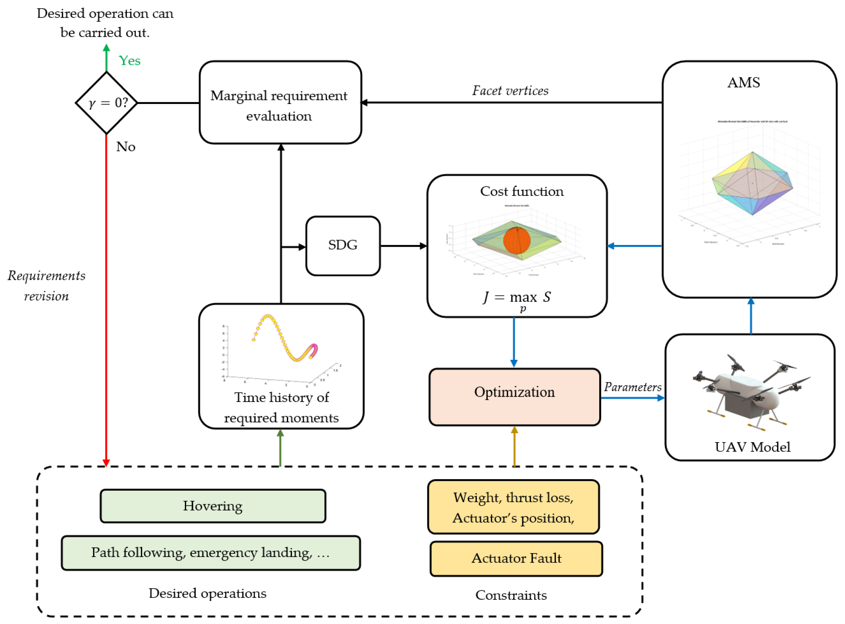
The proposed optimization technique aims to find design parameters that give a multirotor UAV system actuator fault-tolerant capability. As shown in Figure 3, it evaluated the AMS from the initial design parameters and specified the actuator effectiveness value. Firstly, the distribution of moment points is evaluated, and the relative control authority demand is represented as SDG. It checks for the fulfillment of controllability criteria stated in Section 3 by overlaying each required moment point needed to produce the designed mission inside the AMS envelope. The inclusion of all points inside the AMS guarantees the fulfillment of the necessary performance. However, if points exist outside the AMS envelope, the framework maximizes the envelope to include the points. This can be accomplished through fitting and maximizing the SDG to find the largest possible magnification of SDE and the achievable controllability margin by updating design parameters, such as the actuator tilting angle, considering actuator health conditions. Therefore, the optimization outcome will be a set of design parameters that grant actuator fault tolerance. This parameter can be stored in lookup tables and used to reconfigure a system.

4.2. Optimization Formulation

For a given set of design parameter p that describes the UAV configuration, the set of actuator failure possibilities ξ , and the defined mission requirement, the optimization problem was formulated as the fitting geometry of the mission profile moment requirement into an AMS convex polytope.
As shown in Figure 4, a 2D example of moment data points of various mission requirements demonstrates the formulation visually. The first mission demands equal control authority in all moment directions; in contrast, the second data set requires higher strength in one of its directions, resulting in weighted control authority requests. Both data distribution are represented geometrically as a circle and an ellipse using Equations (11)–(14), respectively, and the concentric geometries portray different levels of their magnification. Similarly, the violet polygon signifies the AMS, whereas the concentric convex polytope (broken line) shows the marginal constraint. Recalling the properties of the AMS and controllability criteria, sufficient magnification, and fitting of these geometries into the AMS by adjusting design parameters ensure the enclosure of the required moment point within the geometries and inside the AMS.
For the first case, the above statement can be formulated mathematically by using Equations (9)–(11) as a problem of fitting and maximizing directly the radius of spheroid subjected to an inequality equation that describes the AMS polytope:
m a x i m i z e   S Subject   to ,   S B f i + 2 + B f i + T o u i   for   i = 1 , 2 , , n   u i , m i n < u i < u i , m a x S > 0
The effect of actuator failure was considered through a modified effectiveness matrix that features the actuator health status indicator in Equation (10):
B f + = ( B f ( ξ ) ) +
where B f + is the pseudo inverse of B f subjected to a set of actuator failure possibilities ξ .
For the second case, where the required moments are directionally distributed, the problem is modified by Equation (14):
m a x i m i z e   log det ( S W ) Subject   to ,   S W B f i + 2 + B f i + T o u i   for   i = 1 , 2 , , n u i , m i n < u i < u i , m a x S > 0
Note that the formulation can be verified by computing the confidence level p , corresponding to scale factor s , which defines the probability of randomly scattered required moment data points falling inside the magnified geometry, as shown in Table 1. For a three-dimensional SDE, a scaling factor S 5 gives a confidence level of 1.

4.3. Inside-AMS-Point Check

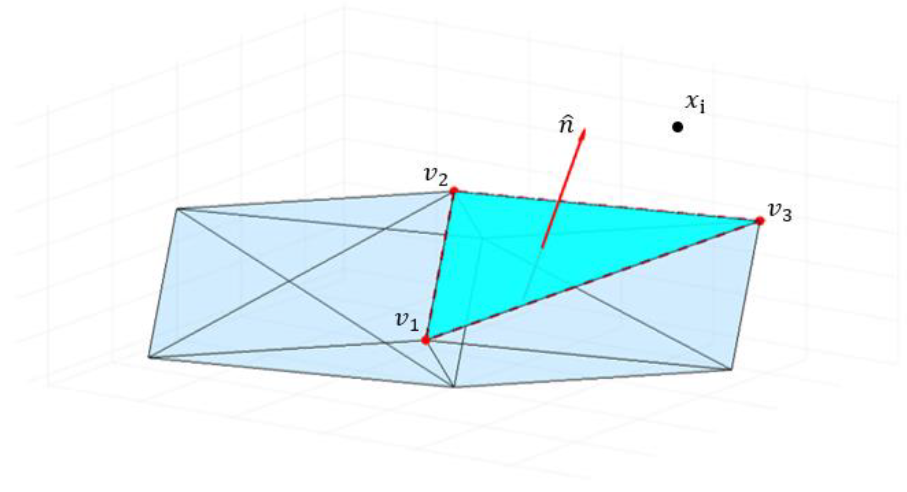
In this section, Algorithm 1 is proposed to check the orientation of required moment points relative to the AMS and address the issue of marginal requirement. In a convex polytope analysis, each facet is a hyperplane that divides a space into half-spaces. As shown in Figure 5, conventionally, the normal vector of a convex polytope facet is supposed to be oriented to the exterior [15]. On the other hand, the signed distance between an arbitrary point x i and a plane tells the orientation of the point relative to that plane. The positive distance indicates the existence of a point x i on the same side of the facet normal vector n ^ , and negative if it is on the opposite side [16]. Therefore, if the distance of each required moment data point from all facets of the AMS is negative, it shows the existence of all points inside the AMS envelope.
i is a triangular facet of an AMS with the vertex v j = [ v j x   v j y   v j z ] , where i = 1 , 2 , , 2 C 2 m and j = 1, 2, 3 number of vertexes.
The normal unit vector to a facet of an AMS can be given as follows:
n ^ = ( v 2 v 1 ) × ( v 3 v 1 ) | ( v 2 v 1 ) × ( v 3 v 1 ) |
The signed distance d j between an arbitrary point x 0 and a facet of an AMS can be calculated as for all vertices on the facet:
d j = n ^ · ( x 0 v j )
If all vertices lay on the same plane, the signed distance should be:
d 1 = d 2 = d 3 = d
The determination of the point orientation relative to the AMS can be summarized based on the sign d as follows:
f   d = { < 0 the   point   is   inside   of   AMS   > 0 the   point   is   outside   of   AMS = 0 on   the   boundary   of   AMS
In case marginal requirement ζ + is prescribed, the criteria can be modified as follows:
if   d = { < - ζ the   point   is   inside   AMS   upto   specified   margin   > - ζ the   point   is   outside   from   specified   margin = - ζ on   specified   margin
The pseudo-code below describes the procedures involved in determining the orientation of moment points about the AMS.
Algorithm 1 Inside-AMS-point check
1 x i   for i = 1, 2,…,n required moment with n number of points
2 j is a facet from AMS for j = 1 ,   2 2 C 2 m
3 v k j for k = 1, 2, 3 vertices of AMS facet
4 ζ marginal requirement
5for all i
6     for all j
7       for all k
8         n = norm ( j )  //norm vector for each facet
9          d = dot (n, ( x i v k j )  //signed distance between each facet and points in a
            moment’s history
10   If  d > ζ
11     outside point= h i           // h i is outside of the AMS
12   Else if d < ζ
13     inside point= h i           // h i is inside the AMS
14If z* = size(outside point)! = 0
15     performance requirement not fulfilled
16If z* = size(outside point) = 0
17     performance requirement fulfilled
Our proposed optimization framework uses this algorithm to assess whether performance criteria are met for specified marginal requirements. Furthermore, the number of points residing outside of the margin of the AMS for an arbitrary S can be quantified using by exclusion ratio γ , as expressed:
γ = Z * Z
where 0 γ 1 and it is defined as the ratio of the set of points outside the margin of the AMS Z * to the set of all points of the required moment Z . γ = 0 indicates the existence of all points inside the AMS, whereas γ = 1 implies the existence of all points outside the AMS envelope.

5. Implementation

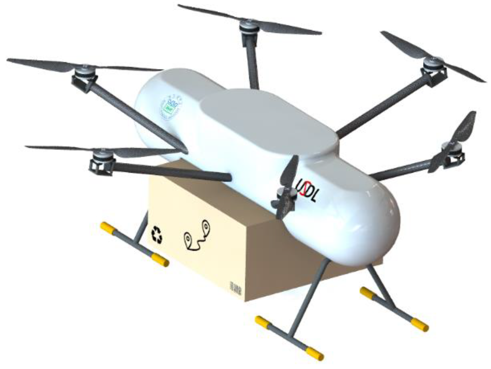
The proposed method was implemented on parcel delivery Hexarotor UAV developed by a PNU drone to optimize its actuator tilting angle and arm installation angle. This implementation aimed to validate the presented approach and show functional application practices of the computed parameters through a simulation of the assumed UAV.
The preliminary design of the assumed UAV had a standard coplanar configuration, as shown in Figure 6. The output of the proposed method for possible actuator’s complete failure one at a time and desired post-failure operations were computed. The possible practice of deploying this optimized tilting angle for reorienting the actuators is using an active tilting mechanism, as shown in Figure A1. These situations were demonstrated with a simulation in its hovering and path-following mission.

5.1. Plant Modeling and Simulation

In this work, a simulation of an assumed UAV was presented. Although the detailed modeling process of the system is beyond the scope of this study, a subjective description of the level of abstraction related to actuator failure and reconfigurability mechanisms is elaborated in this section.
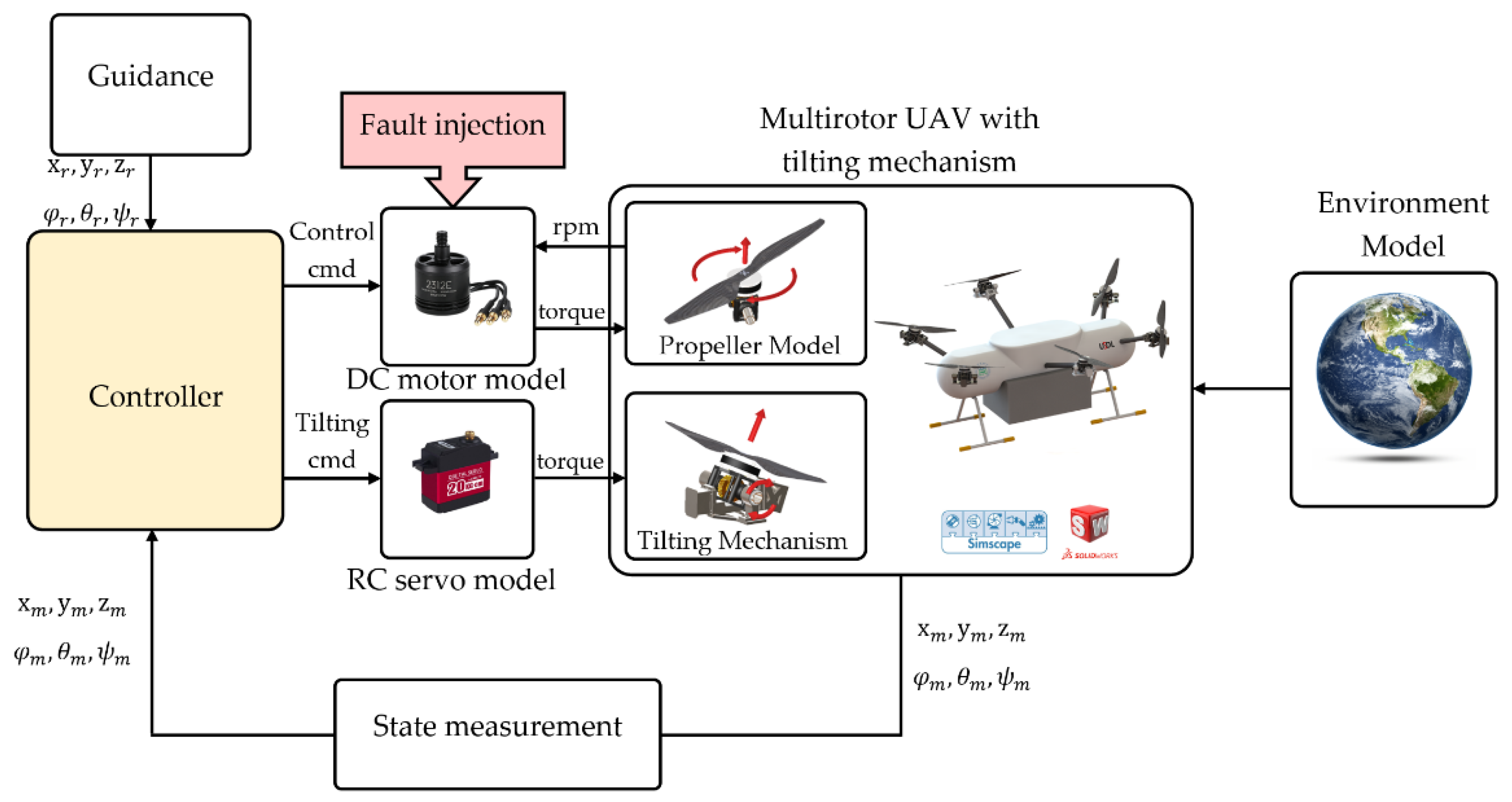
Nowadays, the advancements of modeling software and efficient computers enable the simulation of highly abstracted models. Multibody modeling tools allow the development of high-fidelity simulation models without getting into the complexity of the mathematical modeling of a system [17]. In this modeling process, SOLIDWORKS 3D CAD modeling software was employed to model the digital copy of the UAV structure with its inertial parameters. In contrast, physical models, such as D.C. motors, R.C. servo motors, and other relevant components, were modeled with Simscape MultibodyTM. It is an extension of MATLAB/Simulink. It has tools to simulate a mechanical system with multiple degrees of freedom which allows modeling the individual components and their integration, including their energy interaction [18]. The library contains all the blocks required to define physical systems, such as bodies, joints, actuators, and sensors. The solver simulates the dynamics of the physical system by developing and solving differential equations [19].
The block diagram of the UAV HFM developed in Simscape MultibodyTM is shown in Figure 7. Inside the UAV block, the inertial properties of the UAV were defined by a body block that contained a CAD file of the UAV airframe. Based on the XML file generated from CAD, the relative position and orientation of components were specified by transformation block models, whereas the relative motion constraints were modeled in the joint block. The propulsion system was composed of two central units. The first unit was responsible for generating thrust, and it had a D.C. motor model block and propeller model block, while the second unit was responsible for vectorizing the generated thrust, and it had an R.C. servo motor model block and tilting mechanism model.
Furthermore, these actuation blocks allow fault injection at a specified simulation time. The environmental model block was applied to define the gravitational force and model contact between the UAV and CAD modeled ground and obstacles. The translation and rotational state of the UAV with respect to the world reference were measured by transform sensor block. The propellers’ angular rate and tilting angles were measured by sensor option on the respective joint block during the simulation. The model blocks are configured according to the manufacturer’s datasheet of selected components.
The controller block receives the position setpoint from the waypoint-based trajectory generator and the state of the UAV from the state measurement block. It outputs the control signal to the actuator block. The stabilization and control of the plant were implemented in the control block, which uses the cascaded closed-loop PID position and attitude control. The precomputed tilting angles combined with the fault tag are stored in the lookup table to reconfigure the UAV [20,21,22]. In this test platform, by assuming the presence of a perfect actuator fault detection and isolation system, fault signals were generated automatically, and corresponding reconfiguration parameters were selected after some detection time. Thus, each tilting mechanism servo received an actuation signal and executed structural reconfiguration.

5.2. Parameter Selection

The preliminary design of the proposed UAV had six equally spaced propellers on the same plane. The propellers were arranged in alternating order of their spinning direction. The propellers’ counterclockwise (CCW) rotation about the Z-axis of the propeller coordinate was taken as positive rotation, whereas the clockwise rotation was assumed as negative, and the thrust generated by the propellers was directed parallel to both the airframe and propeller coordinate Z-direction. Even though it was not fully controllable, this arrangement fulfilled the minimum number of propellers required to provide actuator fault tolerance [23].
Recalling the discussion in Section 1, actuator failure causes the loss of force and moment unbalance, which results in an incapability to maintain entire attitude and altitude control. A typical scheme for solving this situation is scarifying control of one or more DOF, usually yaw motion to control rolling and pitching motion independently [24]. Vectorizing thrust by tilting the propeller was another technique many researchers presented. The inward, sideways, or combined tilting of propellers proved to enhance the multirotor UAVs’ fault tolerance and maneuverability [25,26,27].
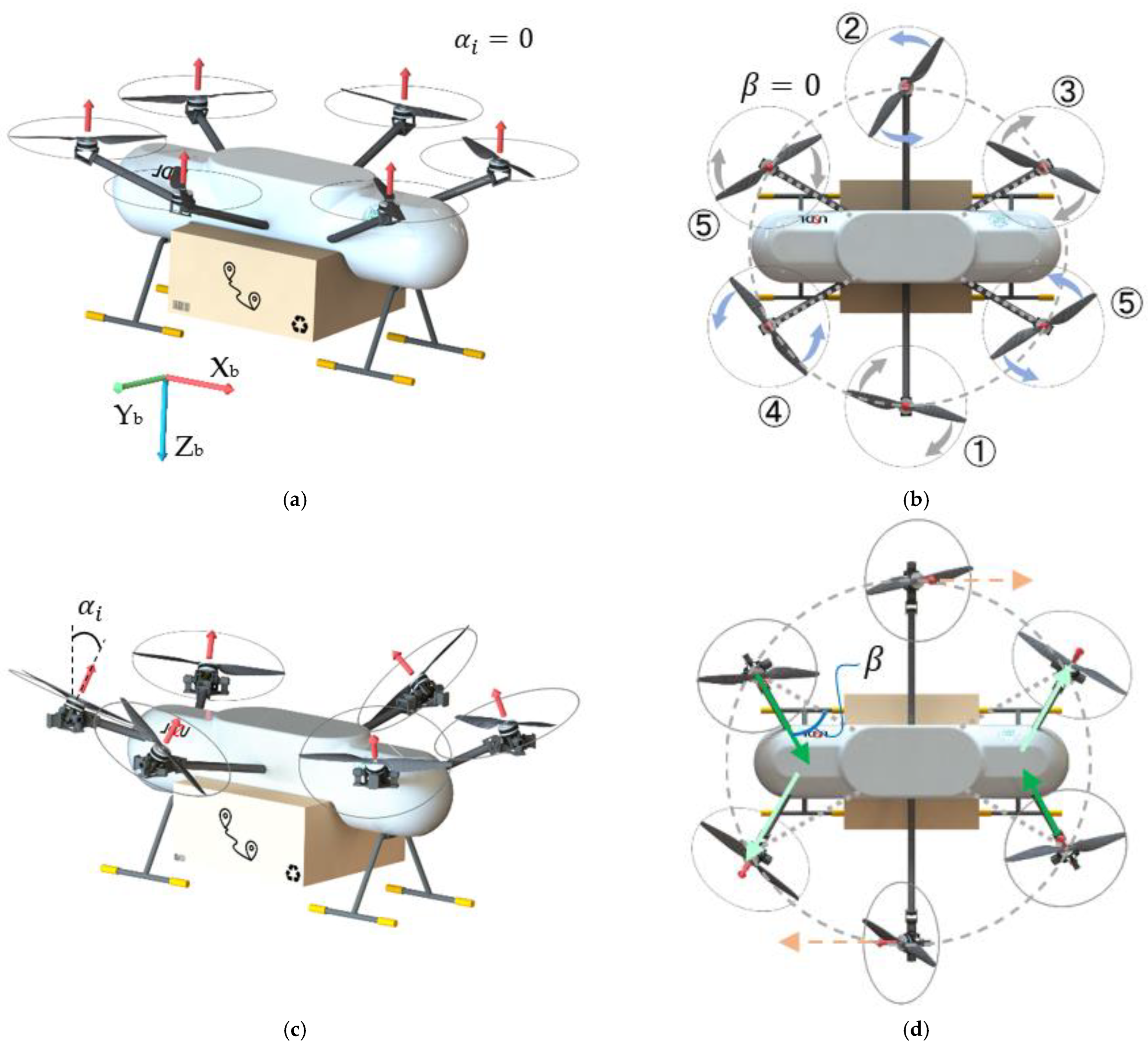
Thus, as shown in Figure 8, actuators 3–6 were established to tilt inward and outward about the axis perpendicular to the arm axis. In contrast, actuators 1 and 2 were situated to make sideways tilting about the arm axis. The additional parameter β controls the deviation between the lateral thrust vector produced by the vectorization of the thrust produced by tilting the propellers and the arm axis. Angle β results in offsetting two symmetric and opposite propellers’ lateral thrust. Figure 8c,d shows the modified configuration of the preliminary design shown in Figure 8a,b. The green line represents the direction of the lateral thrust offsetting by β , whereas the grey line represents the preliminary design arm axis.
The design parameters to be optimized were chosen as:
p = [ β , α 1 , α 2 , α 3 , α 4 , α 5 , α 6 ] T
where α i is the propeller’s tilting angle, and β is the lateral thrust offsetting angle; the outward tilting angle was taken as a positive tilting angle.

6. Result and Discussion

6.1. Optimization Result

The proposed framework’s verification by optimizing parameters in p for each actuator failure possibility in the platform and chosen post-failure operation performance requirement is presented. The two common operations, hovering at the location and following an obstacle-free trajectory to return home, are considered. The required moment data to accomplish these operations and reject the associated disturbance in the nominal condition were logged from the simulation and used as a performance requirement for optimization in faulty conditions. If the framework is implemented correctly, the parameters must converge to a value that gives a maximum cost function and the least exclusion ratio for a given marginal demand. If this is violated, the parameters should not be accepted as optimum, and we recommend that the operation and parameter constraints be revised. In order to limit the maximum vertical thrust loss due to tilting to 5% and consider installation constraints, the domain of parameters is defined as follows:
D   = { p | 0   <   β   <   30 ,   - 20   <   α i   <   20 ,   i = 1 , 2 6 }
To perform the optimization, the particle swarm optimization (PSO) algorithm was implemented to search for a combination of parameters that maximizes the cost function. The algorithm used randomly distributed population sizes of 500 and 400 iterations.

6.1.1. Null Controllability

This section presents the optimization result of the assumed UAV towards achieving actuator fault-tolerant capabilities in a single actuator total failure while hovering. The framework used Equation (15) to maximize and fit the sphere described in Equation (11) into the AMS, and Figure 9 shows the result as a plot of parameters and cost function against the number of iterations for actuator-1 total failure. The result showed that the parameters were converged to values that maximize the cost function within their constraint limits. The initial values, optimal values, and the resulting cost function computed by the optimization framework for each actuator’s possible failure are listed in Table 2.
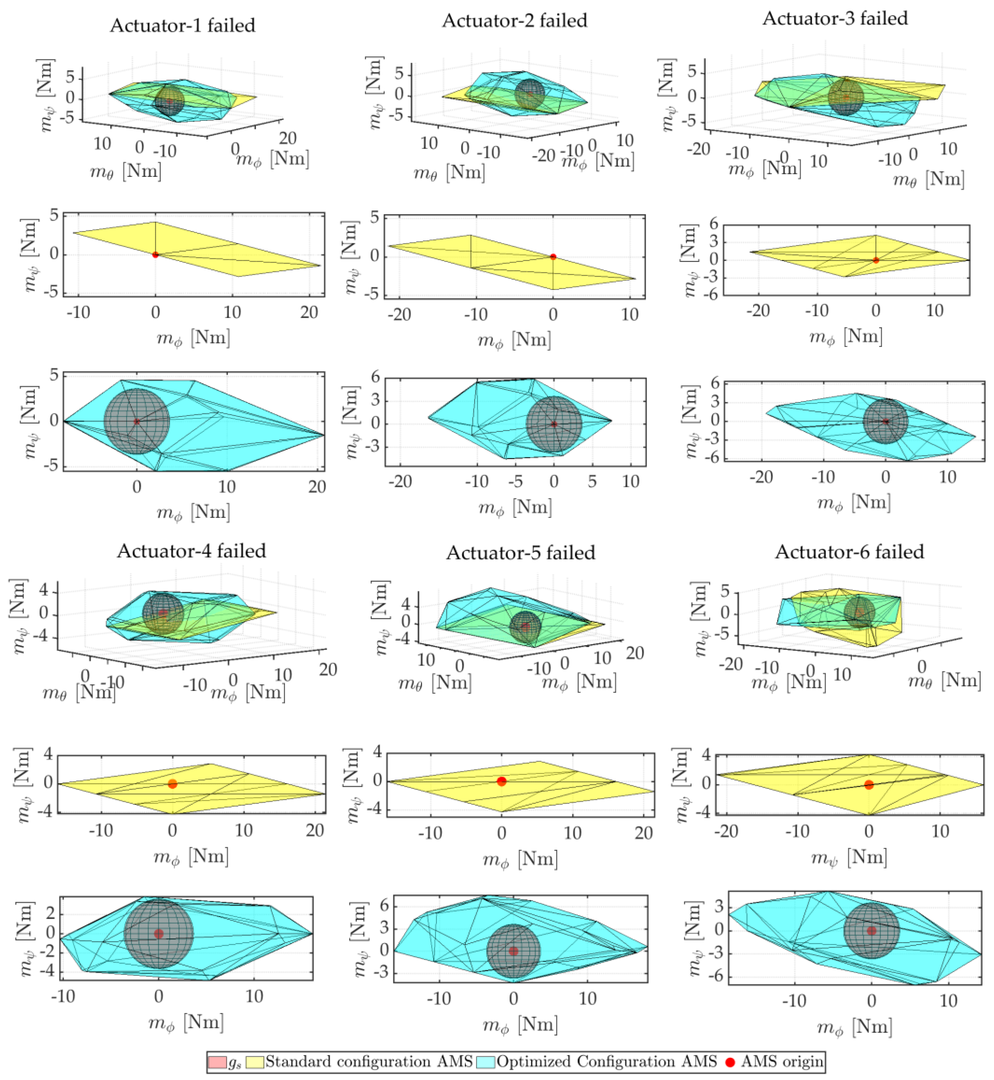
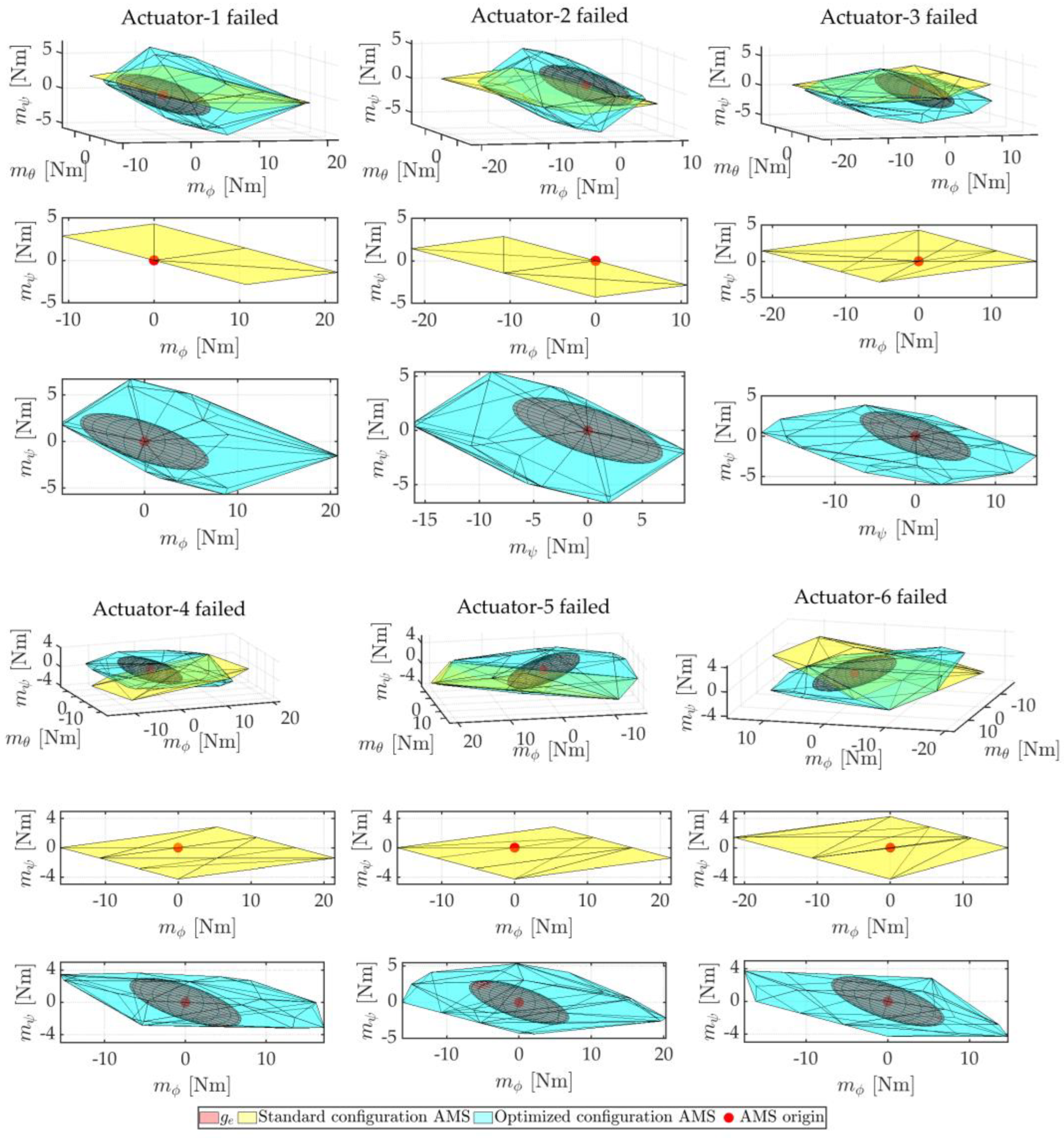
A comparison of the preliminary designs of the AMS (yellow) and the configuration augmented with optimum parameters (aqua) for each actuator’s failure is presented in Figure 10. In preliminary design, actuator-1 total failure results in an inability to produce a negative yaw moment and a negative roll moment simultaneously, and actuators-2 total failure results in an inability to produce a positive yaw moment and a positive roll moment. Likewise, the complete failure of actuators-3–4–5–6 degrades the system’s controllability, so the system loses its attitude control. In contrast, owing to the vectorization of the vertical thrust force into the lateral force via optimum angle tilting and arm installation angle of the produced lateral force from symmetrically located actuators, the yaw moment was produced independently with a slight loss of roll moment in the optimal configuration. As a result, sufficient control was produced around the origin of the AMS, as shown on the optimized configuration AMS by origin-centered sphere geometry.
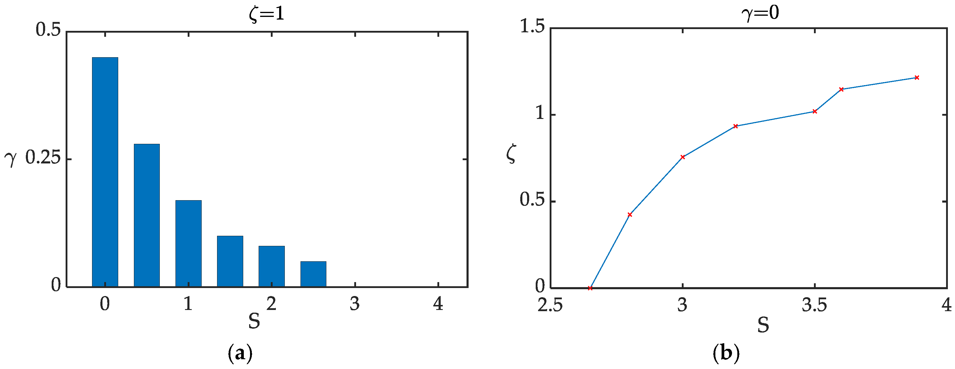
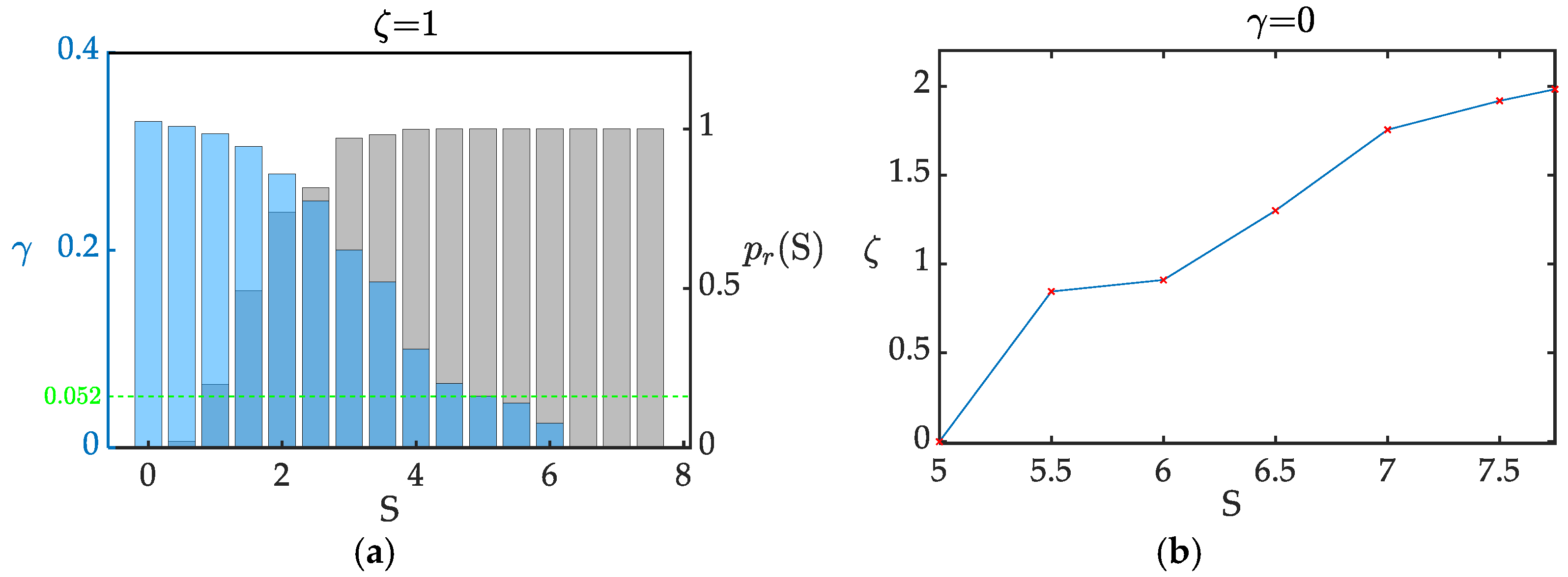
The marginal evaluation result for actuator 1 failure optimization is depicted as shown in Figure 11. The actuator-1 failure in the preliminary design results in S = 0 and γ = 0.462 , which indicates 46.2% of the required moment points outside the AMS envelope, as shown in Figure 11a. Given the marginal value of ζ = 1 , the coverage of all points within the prescribed margin was ensured through the magnification of g s by S = 3.26 . Furthermore, Figure 11b shows the maximum achievable scaling factor S = 3.886 and the corresponding marginal value of ζ = 1.316 .

6.1.2. Maneuver Requirement

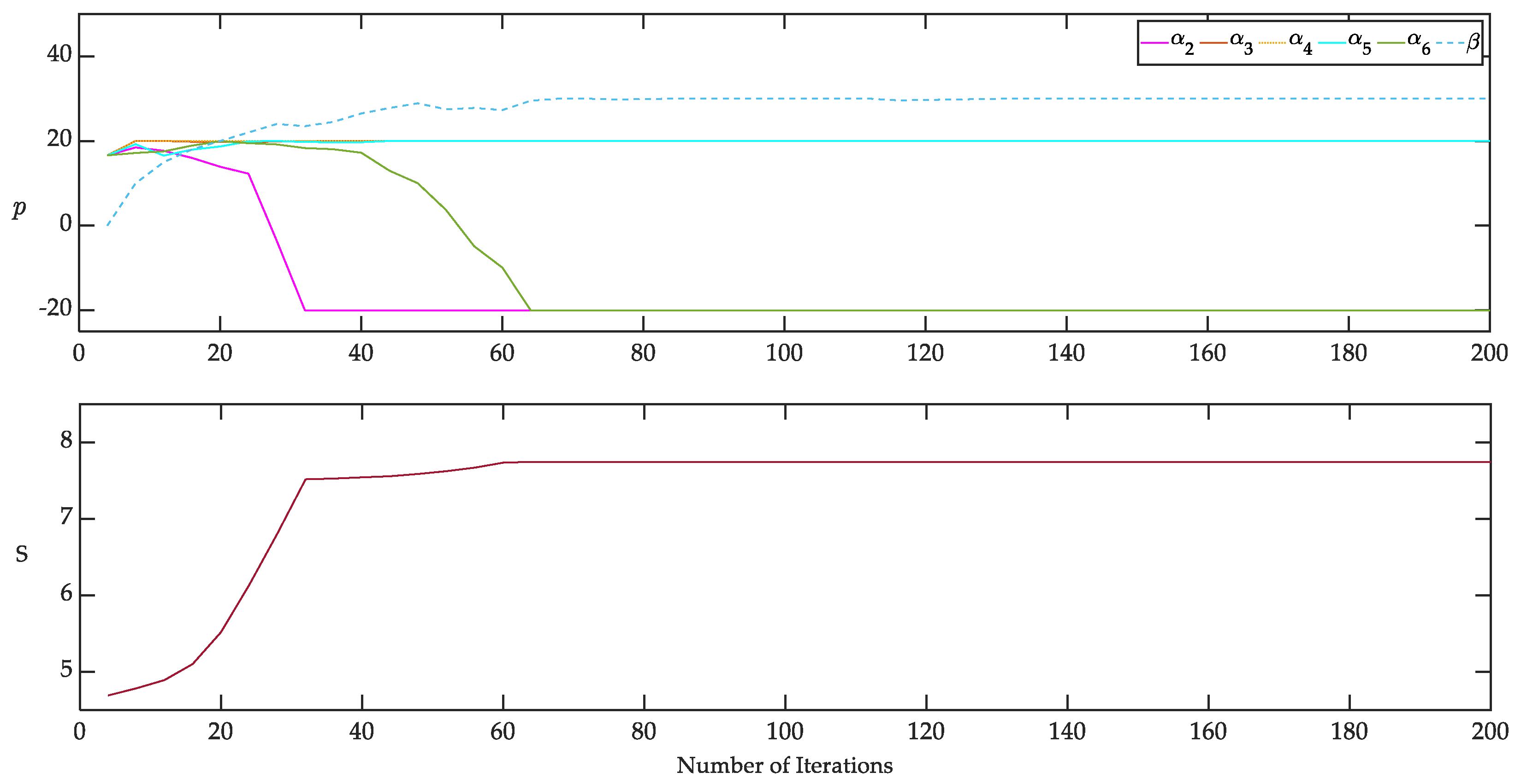
In this case, the proposed framework was used to find the optimum design parameters that would allow the system to execute its assigned mission in the event of an actuator failure. The required moment data to track mission trajectory were obtained from the assumed UAV model simulation at nominal conditions. The distribution of moment data points in its three directions of moment space 3 was portrayed geometrically by constructing the SDE using Equations (12)–(14). The framework used Equation (17) to maximize and fit the SDE described by Equation (14) into the AMS, and Figure 12 shows the result as a plot of parameters and cost function against the number of iterations. Similarly, the parameters were converged to values that maximize the cost function within their constraint limits.
Similarly, a comparison of the preliminary design of the AMS (yellow) and the configuration augmented with optimum parameters (aqua) for each actuator’s failure is presented in Figure 13. Unlike the hovering operation, the maneuver requires different control authorities in all moment directions in this operation. In this case, the optimization fits Equation (14), which describes the required moments to meet the assigned maneuver into the AMS using the formulation in Equation (17). Similarly, the results demonstrated that sufficient control authority was obtained in all directions, based on their relative weight. The initial values, optimal values, and the resulting cost function computed for each actuator’s possible failure are listed in Table 3.
Using Algorithm 1 given in Section 4, the orientation of points can be defined using the exclusion ratio γ and confidence level p r ( S ) given marginal value ζ for an arbitrary value of scale factor S, as shown in Figure 14a. In the preliminary design, failure in actuator one results in a loss of controllability in one of the directions; hence, the geometry will have zero radii that result in S = 0 and the corresponding p r ( S ) = 0 . In this circumstance, about 1 3 of the moments required to perform the needed operation were present outside of the AMS envelope. As S increases, the number of points flowing into the AMS polytope increases, whereas the number of points outside the envelopes decreases, as indicated by decreasing of γ . At S = 5 the confidence level reaches a maximum p r ( S ) = 1 , which shows the existence of all points within the ellipsoid and hence in the AMS envelope. However, 5.2% of points reside outside the AMS’s prescribed margin. Further magnification of the ellipsoid results in the enlargement of the AMS and crossing of the remaining points across the specified margin inside the AMS. At S = 6.35 all points were orientated inside of the requested margin.
Moreover, the maximum marginal value that can be imposed is depicted in Figure 14b. At ζ = 0 all points are orientated inside the AMS polytope without marginal specification. For ζ > 0 , the polytope must be enlarged to keep γ = 0 . As a result of imposed constraint on the parameter, the maximum marginal value that can be achieved was ζ = 2.05 , which corresponds to the maximum scale factor ( S = 7.747 ). Therefore, the computed parameters can be used to reconfigure the UAV to tolerate the considered fault and perform the desired maneuver.

6.2. Simulation Result

6.2.1. Scenario 1

The assumed UAV model simulation was used to prove the optimized configuration’s ability to survive specified actuator failure while hovering at the target as shown in simulation Video S1. As shown in Figure 15, the UAV with the preliminary actuator orientation was commanded to take off to six meters and hover. While hovering, the fault was injected into actuator1 at a simulation time of 20 s, and the propellers were steered to tilt after sufficient detection time. The simulation result demonstrated that the optimum configuration compensated for the lost control after some perpetuation and stabilized towards its hovering state, as shown in Figure 16.

6.2.2. Scenario 2

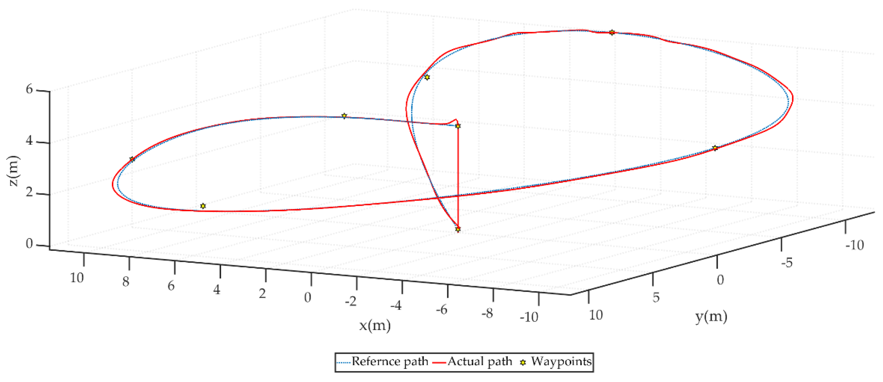
In this scenario, the ability of a configuration with optimum design parameters to navigate via waypoints was evaluated in the event of a single actuator failure. The waypoints are positioned so that they reflect the tasks that are carried out to avoid static barriers that may be encountered in real-world applications. The B-spline trajectory generating technique established in [28] was used to combine the waypoints as shown on Figure 17.
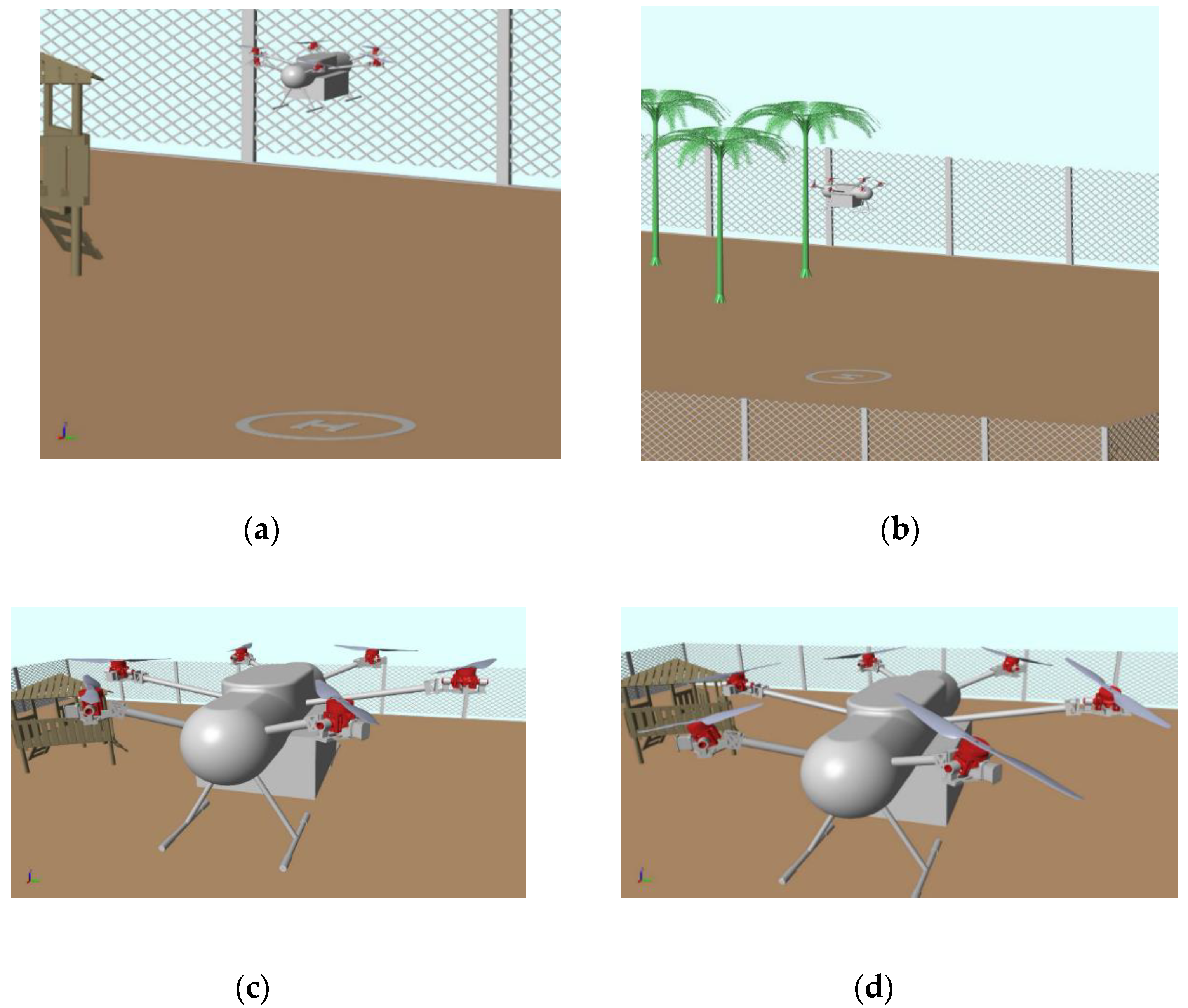
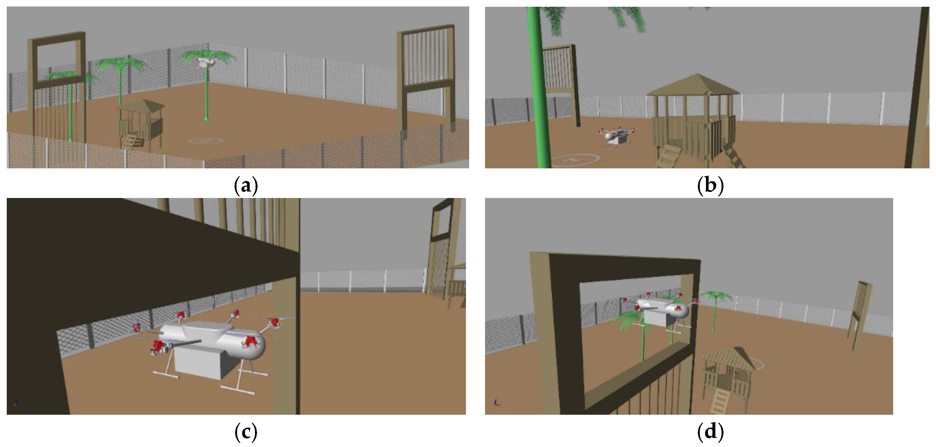
As shown in Figure 18, the possible environmental confrontation is depicted as windows at different heights, trees, and a house. The first window was placed in such a way that it allowed the UAV to pass at a lower altitude below two meters, whereas the second window was placed at the height of six meters. Following the mission profile, the UAV was ordered to take off to the altitude of four meters (Figure 18a) pitch forward about ten meters, and follow the curved path to the first and second window obstacles while rolling, pitching, and descending to the height of two meters simultaneously (Figure 18c). Then it had to ascend simultaneously to an altitude of six meters (Figure 18d) to pass through the opening, and finally land at the depicted landing pad (Figure 18b). Therefore, in this flight path, the performance of the optimized configuration during a single actuator failure was conducted to fulfill the specified operation.
The UAV was reconfigured to the optimum propeller tilting and offset angle listed in Table 3 corresponding to the actuator-1 failure. As shown in Figure 19, the result showed that the desired operation is fulfilled while the actuator-1 failed with optimized parameters.

7. Conclusions

This work proposed a reliable optimization strategy that can be employed to design actuator fault-tolerant multirotor UAV configuration. The framework considers the required moment data derived from the designed mission profile and disturbance rejection requirement. Given the required moment as a geometry that describes its distribution and the actuator’s health status indicator, the optimizer aims to maximize the scaling factor of the geometry and fit into the AMS, such that the requirements lay under the system capability in the presence of a failed actuator. An efficient marginal evaluation algorithm is proposed to quantify the extent of capability margin. The framework is applied to the delivery drone concept developed by the PNU drone with six rotors. The assumed UAV is modified with a one-direction rotor active tilting mechanism to allow the system to reconfigure itself in the event of failure and recovery. Firstly, the strategy is verified by a multivariable optimization of selected design parameters for performing a given task under fault conditions, and the resulting trend of the cost function and parameter was plotted. The optimization result shows that the proposed approach maximizes the AMS to enclose requirements under system capability, and the resulting cost function is clearly plotted against the exclusion ratio to show the orientation of points relative to the AMS. The author believes that this work is a fundamental and essential step in designing fail-safe operations, such as obstacle-free trajectory, safe landing site search, etc.

Supplementary Materials

The following supporting information can be downloaded at: https://www.mdpi.com/article/10.3390/app12136781/s1, Video S1: Simulation of actuator fault tolerant multirotor UAV with tilting actuators.

Author Contributions

Conceptualization, Y.D.; methodology, Y.D.; software, Y.D. and H.-Y.S.; validation, Y.D. and A.W.; investigation, Y.D. and H.-Y.S.; writing original draft preparation, Y.D.; writing review and editing, Y.D., H.-Y.S. and A.W.; visualization, Y.D. and J.-H.K.; supervision, B.-S.K. All authors have read and agreed to the published version of the manuscript.

Funding

This work was supported by the National Research Foundation of Korea (NRF) grant funded by the Korean government (MIST) (No. 2012R1A5A1048294).

Conflicts of Interest

The authors declare no conflict of interest.

Appendix A. Position and Orientation Matrix Derivation

The relationship between the design parameters and the force and moment generated can be summarized as follows:
Figure A1. Structural layout of proposed UAV.
Applsci 12 06781 g0a1
The propeller’s position can be described with rotation about the body frame Z b axis by angle θ as shown in Equation (3) in Section 2. The generalized position matrix x of the assumed Hexarotor UAV preliminary configuration shown is defined as:
x = [ 0 0 s ( θ ) s ( θ ) s ( θ ) s ( θ ) c θ c θ c ( θ ) c ( θ ) c ( θ ) c ( θ ) 0 0 0 0 0 0 ]
Referring from Section 5, for optimization purposes, the orientation matrix was modified with offsetting angle β as:
x ^   = [ 0 0 s ( θ β ) s ( θ β ) s ( θ β ) s ( θ β ) c ( θ β ) c ( θ β ) c ( θ β ) c ( θ β ) c ( θ β ) c ( θ β ) 0 0 0 0 0 0 ]
The orientation of each propeller can be computed as the successive rotation of the arm with an angle θ about the body frame Z b axis and about propellers coordinate axis y p and x p with angles α y and α x , respectively.
R Z b ( θ ) = [ c θ s θ 0 s θ c θ 0 0 0 1 ]
R y p ( α y ) = [ c α y 0 s α y 0 1 0 s α y 0 c α y ]
R x p ( α x ) = [ 1 0 0 0 c α x s α x 0 s α x c α x ]
From Equation (4), the generalized propellers orientation matrix is given as:
q = [ s ( α 1 ) s α 2 s ( θ ) s α 3 s ( θ ) s α 4 s ( θ ) s α 5 s ( θ ) s α 6 0 0 c ( θ ) s α 3 c ( θ ) s α 4 c ( θ ) s α 5 c ( θ ) s α 6 c α 1 c α 2 c α 3 c α 4 c α 5 c α 6 ]
Recalling from Section 2 for opmization purposes, the orientation matrix can be modified with offsetting angle β as:
q ^ = [ s α 1 s α 2 s ( θ β ) s α 3 s ( θ β ) s α 4 s ( θ β ) s α 5 s ( θ β ) s α 6 0 0 c ( θ β ) s α 3 c ( θ β ) s α 4 c ( θ β ) s α 5 c ( θ β ) s α 6 c α 1 c α 2 c α 3 c α 4 c α 5 c α 6 ] .  

References

  1. Fourlas, G.K.; Karras, G.C. A Survey on Fault Diagnosis and Fault-Tolerant Control Methods for Unmanned Aerial Vehicles. Machines 2021, 9, 197. [Google Scholar] [CrossRef]
  2. Baldini, A.; Felicetti, R.; Freddi, A.; Longhi, S.; Monteriù, A. Actuator Fault-Tolerant Control Architecture for Multirotor Vehicles in Presence of Disturbances. J. Intell. Robotics Syst. 2020, 99, 859–874. [Google Scholar] [CrossRef]
  3. Pose, C.D.; Giribet, J.I.; Mas, I. Fault Tolerance Analysis for a Class of Reconfigurable Aerial Hexarotor Vehicles. IEEE/ASME Trans. Mechatron. 2020, 25, 1851–1858. [Google Scholar] [CrossRef]
  4. Schneider, T.; Bouabdallah, S.; Rudin, G.D.K. Fault-Tolerant Multirotor Systems. Master’s Thesis, ETH Zurich, Zürich, Switzerland, 2011. [Google Scholar]
  5. Michael, A.; Klaus, M.D.; Danie, G.; Jan, S. Design of a Multi Rotor MAV with regard to Efficiency, Dynamics and Redundancy. In Proceedings of the AIAA 2012-4779, AIAA Guidance, Navigation, and Control Conference, Minneapolis, MN, USA, 13–16 August 2012. [Google Scholar]
  6. Sanjuan, A.; Nejjari, F.; Sarrate, R. Reconfigurability Analysis of Multirotor UAVs under Actuator Faults. In Proceedings of the 2019 4th Conference on Control and Fault Tolerant Systems (SysTol), Casablanca, Morocco, 18–20 September 2019; pp. 26–31. [Google Scholar] [CrossRef]
  7. Yang, T.; Li, P.; Zhang, H.; Li, J.; Li, Z. Monocular Vision SLAM-Based UAV Autonomous Landing in Emergencies and Unknown Environments. Electronics 2018, 7, 73. [Google Scholar] [CrossRef] [Green Version]
  8. Wayne, D.; Kenneth, A.B.; Roger, B. Aircraft Control Allocation; Wiley: Chichester, UK, 2017. [Google Scholar]
  9. Wang, B.; Shi, W.; Miao, Z. Confidence Analysis of Standard Deviational Ellipse and Its Extension into Higher Dimensional Euclidean Space. PLoS ONE 2015, 10, e0118537. [Google Scholar] [CrossRef] [PubMed]
  10. Wolfgang, K.H.; Léopold, S. Applied Multivariate Statistical Analysis; Springer: Berlin/Heidelberg, Germany, 2015. [Google Scholar] [CrossRef]
  11. Gong, J. Clarifying the Standard Deviational Ellipse. Geogr. Anal. 2002, 34, 155–167. [Google Scholar] [CrossRef]
  12. Jiang, G.; Richard, M.V. A nonparallel hexrotor UAV with faster response to disturbances for precision position keeping. In Proceedings of the 2014 IEEE International Symposium on Safety, Security, and Rescue Robotics, Hokkaido, Japan, 27–30 October 2014; pp. 1–5. [Google Scholar]
  13. Zhang, J.; Max, S.; Florian, H. Attainable Moment Set Optimization to Support Configuration Design: A Required Moment Set Based Approach. Appl. Sci. 2021, 11, 3685. [Google Scholar] [CrossRef]
  14. Wen, F.H.; Hsiao, F.Y.; Shiau, J.K. Analysis and Management of Motor Failures of Hexacopter in Hover. Actuators 2021, 10, 48. [Google Scholar] [CrossRef]
  15. Haicheng, L.; Rodney, T.; Peter, V.O.; Martijn, M. Executing convex polytope queries on nD point clouds. Int. J. Appl. Earth Obs. Geoinf. 2021, 105, 102625. [Google Scholar] [CrossRef]
  16. Weisstein, E.W. Point-Plane Distance. From MathWorld—A Wolfram Web Resource. Available online: https://mathworld.wolfram.com/Point-PlaneDistance.html (accessed on 9 May 2022).
  17. Denery, T.; Ghidella, J.; Mosterman, P.; Shenoy, R. Creating Flight Simulator Landing Gear Models Using Multidomain Modeling Tools. In Proceedings of the AIAA Meeting Papers on Disc, (2006-6821), Keystone, CO, USA, 21–24 August 2006; American Institute of Aeronautics and Astronautics: Reston, VA, USA, 2006. [Google Scholar]
  18. MathWorks Inc. Simscape MultibodyTM; MathWorks Inc.: Natick, MA, USA, 2020. [Google Scholar]
  19. Khurrum, M.; Norilmi, A.I. Application of multibody simulation tool for dynamical analysis of tethered aerostat. J. King Saud Univ. Eng. Sci. 2022, 34, 209–216. [Google Scholar] [CrossRef]
  20. Sun, W.; Zhang, X.; Lin, G.; Wang, H.; Han, J. Extreme Maneuvering Control and Planning of Multi-Rotor UAV for High-Speed Invading Target Avoidance. In Proceedings of the 2021 IEEE International Conference on Real-Time Computing and Robotics (RCAR), Xining, China, 15–19 July 2021; pp. 387–392. [Google Scholar] [CrossRef]
  21. Chen, C.; Zhang, J.; Zhang, D.; Shen, L. Control and flight test of a tiltrotor unmanned aerial vehicle. Int. J. Adv. Robot. Syst. 2017, 14, 172988141667814. [Google Scholar] [CrossRef]
  22. Hussein, H. Fault-Tolerant Control of a Multirotor Unmanned Aerial Vehicle under Hardware and Software Failures. Ph.D. Thesis, Université Libanaise, Beirut, Lebanon, 2020. [Google Scholar]
  23. Vey, D.; Lunze, J. Structural reconfigurability analysis of multirotor UAVs after actuator failures. In Proceedings of the 2015 54th IEEE Conference on Decision and Control (CDC), Osaka, Japan, 15–18 December 2015; pp. 5097–5104. [Google Scholar] [CrossRef]
  24. Merheb, A.; Noura, H.; Bateman, F. Emergency Control of AR Drone Quadrotor UAV Suffering a Total Loss of One Rotor. IEEE/ASME Trans. Mechatron. 2017, 22, 961–971. [Google Scholar] [CrossRef]
  25. Giribet, J.I.; Sanchez, R.S.; Ghersin, A.S. Analysis and design of a tilted rotor hexacopter for fault tolerance. IEEE Trans. Aerosp. Electron. Syst. 2016, 52, 1555–1567. [Google Scholar] [CrossRef]
  26. Giribet, J.I.; Pose, C.D.; Ghersin, A.S.; Mas, I. Experimental Validation of a Fault-Tolerant Hexacopter with Tilted Rotors. Int. J. Electr. Electron. Eng. Telecommun. 2018, 7, 58–65. [Google Scholar] [CrossRef] [Green Version]
  27. Michieletto, G.; Ryll, M.; Franchi, A. Control of statically hoverable multi-rotor aerial vehicles and application to rotor-failure robustness for hexacopters. In Proceedings of the 2017 IEEE International Conference on Robotics and Automation (ICRA), Singapore, 29 May–3 June 2017; pp. 2747–2752. [Google Scholar] [CrossRef] [Green Version]
  28. Gauthier, R.; Cristina, S.M.; Sihem, T.; Mathieu, B.; Nicolas, M. Minimum-time B-spline trajectories with corridor constraints. Application to cinematographic quadrotor flight plans. Control Eng. Pract. 2019, 89, 190–203. [Google Scholar] [CrossRef] [Green Version]
Figure 1. Various layouts of multirotor UAVs.
Applsci 12 06781 g001
Figure 2. Visualization of standard deviation geometry scaling and corresponding confidence level.
Applsci 12 06781 g002
Figure 3. Optimization framework.
Applsci 12 06781 g003
Figure 4. 2D visualization of the optimization problem formulation of fitting SDG into the AMS.
Applsci 12 06781 g004
Figure 5. Norm vector and vertex of an AMS facet.
Applsci 12 06781 g005
Figure 6. Preliminary design of urban package delivery drone developed by a PNU drone.
Applsci 12 06781 g006
Figure 7. UAV system modeling and simulation block diagram.
Applsci 12 06781 g007
Figure 8. Comparison of proposed UAV preliminary design and UAV with tilting mechanism (a) preliminary design where all propellers tilting angles are zero (coplanar) (b) preliminary design with axis offsetting angle zero (c) α i tilted propeller configuration (d) configuration with axis offset angle β .
Applsci 12 06781 g008
Figure 9. Optimization output: plot of actuator’s tilting angle and cost function trend against the number of iterations for actuator 1 failure and the null controllability performance requirement.
Applsci 12 06781 g009
Figure 10. AMS comparison of preliminary configuration with optimized configuration for each actuator failure.
Applsci 12 06781 g010
Figure 11. The marginal evaluation results. (a) Exclusion ratio for sampled scaling factors at marginal value ζ = 1 (b) Achievable marginal requirement.
Applsci 12 06781 g011
Figure 12. Optimization output: plot of actuator’s parameters and cost function trend against the number of iterations for actuator 1 failure and prescribed maneuver performance requirement.
Applsci 12 06781 g012
Figure 13. AMS comparison of preliminary configuration with optimized configuration for each actuator failure and prescribed maneuver performance requirement.
Applsci 12 06781 g013
Figure 14. The marginal evaluation results for designed mission profile (a) Trend of exclusion ratio and confidence level against cost function at a different stage of design parameter optimization is plotted at ζ = 1 ; (b) Achievable marginal requirement.
Applsci 12 06781 g014
Figure 15. Simulation for hovering flight (a) Hovering at a given height in the nominal situation. (b) Right-side view of hovering at a given height in the presence of actuator failure. (c) Close-up view of hovering flight before actuator failure. (d) Close-up view of actuator’s reorientation after actuator failure at recovered hovering.
Applsci 12 06781 g015
Figure 16. Hovering test result for fault injected at t = 20 s on propeller (a) Altitude of the vehicle (b) Attitude response (c) Propeller tilting angle (d) Propeller’s rotation rate.
Applsci 12 06781 g016
Figure 17. The path followed by the UAV.
Applsci 12 06781 g017
Figure 18. Trajectory following simulation result with actuator-1 failed (a) Take-off (b) Landing (c) Passing through obstacle 1 (d) Passing through obstacle 2.
Applsci 12 06781 g018
Figure 19. Simulation result of the optimized configuration in tolerating actuator 1 failure and performing maneuvers.
Applsci 12 06781 g019
Table 1. Confidence level of scaled SDE for different scaling factors and dimensions [9].
Dimensionality
(n)
Scale   Factor   S
123456
10.68270.95450.99730.99991.00001.0000
20.39350.86470.98890.99971.00001.0000
30.19870.73850.97070.99891.00001.0000
40.09020.59400.93890.99700.99991.0000
Table 2. Parameter optimizations result in null controllability, single actuator failure at a time.
Fault ConditionParameters (Angles in Degree)Cost Function
Initial ValueOptimization
Actuator 1 failed [ 0 15 15 15 15 15 15 ] [ 30 0 20 20 20 20 20 ] T 3.8862
Actuator 2 failed [ 30 20 0 20 20 20 20 ] T 3.8862
Actuator 3 failed [ 30 20 13.5 0 19 20 20 ] T 3.5078
Actuator 4 failed [ 30 20 13 16 0 20 20 ] T 3.4718
Actuator 5 failed [ 30 20 5 20 19 0 20 ] T 3.6263
Actuator 6 failed [ 30 20 13 20 20 20 0 ] T 3.5029
Table 3. Mission-based parameter optimization results for single actuator failure at a time.
Fault ConditionParameters (Angles in Degree)Cost Function
Initial ValueOptimization
Actuator 1 failed [ 0 15 15 15 15 15 15 ] [ 30 0 20 20 20 20 20 ] T 7.747
Actuator 2 failed [ 30 20 0 20 20 20 10 ] T 8.416
Actuator 3 failed [ 30 20 20 0 20 20 12 ] T 8.595
Actuator 4 failed [ 30 20 20 20 0 20 20 ] T 8.101
Actuator 5 failed [ 30 20 5 20 20 0 10 ] T 8.173
Actuator 6 failed [ 30 20 17 20 20 20 0 ] T 6.751
Publisher’s Note: MDPI stays neutral with regard to jurisdictional claims in published maps and institutional affiliations.