Abstract
Slotting-blasting is the most critical technology in the construction of rock tunnels using the drilling and blasting method. At present, there is no effective method to simulate the effect of slotting-blasting. In this paper, we proposed that the weight coefficient of tension damage or compression damage is calculated by the proportion relation of current principal stresses, and the damage properties of rock were denoted by the tension-compression weighted damage variable. The blasting damage constitutive model of rock was established by coupling the tension-compression weighted damage variable and the classical PLASTIC_KINEMATIC model. The proposed method was used to simulate tunnel slotting-blasting and investigate the rock damage evolution law in slotting-blasting construction. The numerical simulation of the explosive blasting test shows that the proposed method may effectively simulate the slot cavity formation process, the blasting damage law and the dynamic response characteristics of surrounding rock in slotting-blasting construction. The findings in this paper could be significant for the slotting-blasting design of rock tunnels.
1. Introduction
Slotting-blasting is the most critical technology in the construction of rock tunnels using the drilling and blasting method. The methods of applying blasting load and blasting theory affect the engineering application of tunnel blasting numerical simulation results.
There are many ways of applying blasting loads in tunnel engineering. In the past, the blasting load was applied by using the attenuation models such as the triangular impact load model or the exponential function one [1]. The effect of blasting loads is simulated by applying load curves on the hole walls [2,3]. Jones–Wilkins–Lee (JWL) model is a high-energy combustion model. At present, the JWL equation of explosives state is often adopted for the description of detonation products of explosives [4,5,6,7,8,9,10,11,12].
The development of rock blasting theory mainly experienced three stages: elastic-plastic theory, fracture mechanics theory and damage mechanics theory. At present, the blasting damage theories represent the development frontier of rock blasting studies [8].
Using the damage mechanics theory of rock can better simulate the formation and development process from microscopic cracks to macroscopic cracks of rock with native defects [13,14,15,16,17]. Under blasting load, there is the damage phenomenon besides the obvious elastic-plastic deformation for rock. A lot of researchers have studied the problem of rock mass damage caused by blasting and focus on the damage evolution law of rock mass material under blasting load and the mechanism and law of rock mass failure due to crack propagation. The dynamic damage mechanism was firstly introduced by Grady and Kipp (1980) to simulate the blasting process, and they proposed an isotropic rock blasting damage model (the GK model) [18]. The blasting damage models were developed using the damage variable defined by the probability of fracture and considering the effect of loading time on the crack density [4,5]. An elastoplastic blasting damage constitutive model considering rock initial damage was established, and a damage criterion to evaluate the effects of rock blasting damage was proposed [8]. A tension and compression-shear blasting damage model was developed by considering damage patterns of rock mass and the effect of strain rate [9].
Using the numerical simulation technologies of finite element [2,3,4,5,7,8,9,10,11,12,19], the finite difference [1] and discrete element [6,7,10,19] methods can simulate tunnel blasting and investigate the damage evolution law of rock effectively in tunnel drilling and blasting construction. In addition to numerical simulation methods, other methods such as the dynamic caustics blasting experiments [20] and strain gauge method [21] can also be used to investigate the stress wave propagation during slotting blasting and the effect of explosive stress waves on the crack propagation in the defective medium under slitting blasting loading.
At present, rock blasting damage models are rarely used to study tunnel cutting blasting mechanism. Rock is the typical material whose tensile strength and compressive strength are very different. The increment relation of rock stress and strain in the stretched state is different from that in the compressed state. Xie et al. (2016) developed tension and compression-shear damage model to investigate the damage evolution mechanisms of rock in deep tunnels induced by cutting blasting [9]. To fully reflect the contribution of tensile stress damage and compressive stress damage to tunnel cutting blasting, it is necessary to develop a reasonable tension-compression coupling damage model to investigate the damage evolution mechanism caused by rock tunnel cutting blasting.
In this paper, we propose a method to calculate the weighted damage degree denoted by the damage weight coefficient calculated by the proportional relation of current principal stresses to measure the coupled effect of tension stress damage and compression stress damage. Second, the blasting damage constitutive model of rock was established by coupling the proposed tension-compression weighted damage variable and the classical PLASTIC_KINEMATIC model. Third, we proposed a rock tension-compression coupled damage method to simulate tunnel slotting-blasting and investigate the rock damage evolution law in slotting-blasting construction. Four, the coupling approach of the Cowper–Symonds hardening model and the established blasting damage model were used to investigate the damage evolution law of rock in slotting-blasting construction. Finally, some instances were given to verify the availability of the proposed method and to investigate the slot cavity generating process, the blasting damage law and the dynamic response characteristics of surrounding rock in slotting-blasting construction.
The novelty of this paper is that we proposed a rock tension-compression coupled damage method with the damage weight coefficient calculated by the proportional relation of current principal stresses to simulate tunnel slotting-blasting and investigate the rock damage evolution law in slotting-blasting construction.
2. Methodology
2.1. Relationship of Stress-Strain with Damage Variable
In the plastic incremental theory, strain tensor may be denoted by Equation (1).
where is strain tensor; is elastic strain; is plastic strain.
We defined the effective stress using the elastic stiffness without damage (see Equation (2)).
where is effective stress; is initial elastic stiffness without damage.
Assuming that the degradation of material stiffness is considered by the scalar, the material stiffness with damage may be denoted by Equation (3).
where is material stiffness with damage; is damage variable ().
Here, we defined the damage variable by Equation (4).
Stress with damage may be denoted by elastic stiffness degradation and effective stress and has the following form (see Equation (5)).
where is stress with damage.
2.2. Elastic-Plastic Model and Yield Criteria
Stress–strain curves of rock under dynamic load show obvious strain rate-related properties. The yield limit strength of rock obviously increases as the increase in strain rate. In this study, the Cowper–Symonds plasticity with dynamic strengthening model [22] was used to describe the stress-strain relation of rock under blasting load.
On the basis of a large number of experiments, Cowper and Symonds (1958) presented the following empirical formula concerning the dynamic limit yield stress and strain rate [22].
The Cowper–Symonds plasticity with the dynamic strengthening model may be denoted by Equation (6).
where is static limit yield stress; is dynamic limit yield stress; is initial yield stress; C, P are constants of the Cowper–Symonds bilinear elasto-plastic model; is strain rate; is rock hardening parameter; is plastic hardening modulus; is equivalent plastic strain. = 0 when rock shows the plasticity with dynamic strengthening, and = 1 when rock shows isotropic strengthening.
where is tangent modulus; is elasticity modulus; is total strain rate; is elastic strain rate; is plastic strain rate; is time.
The yield surface of rock varies with the states of tension and compression under the blasting load. Rock damage and plastic flow generate at the same time. Rock residual strength decrease with the development of damage. In this study, the dynamic characteristics of rock were denoted by considering the effect of damage on the yield function. According to the damage mechanics theory, the plastic problem may be considered in the effective stress space. Therefore, the yield function is denoted by Equation (10).
where is effective stress strength; , are current yield stress.
where is a component of effective deviatoric stress tensor; is effective stress tensor is the first invariant of stress tensor; is movement tensor at the center of yield surface; is movement tensor increment at the center of yield surface; is effective plastic strain rate; is effective plastic strain; is time increment.
2.3. Tension-Compression Coupled Damage Equation
The statistical damage variable may be defined as the ratio of the number of the destroyed micro-bodies to the total number of micro-bodies, denoted by Equation (12).
where is the total number of micro-bodies; is the number of destroyed micro-bodies.
In this study, we assumed as follows [16].
- (1)
- Rock micro-bodies and rock damage all are isotropic in the macroscopic.
- (2)
- Rock micro-bodies without damage obey Hooke’s law before micro-bodies are destroyed.
- (3)
- The strength of each micro-body obeys the Weibull probability distribution. Because the Weibull probability distribution meets the statistical characteristics of rock compression failure, the probability density function of each micro-body strength obeys the Weibull distribution of two parameters. The probability density function of the Weibull distribution is denoted by Equation (13).where is the distribution variable of random distribution of rock micro-body strength; , are Weibull’s distribution parameters related to rock mechanical properties.
We assumed the failure criterion of rock denoted by Equation (14).
where is rock failure criteria; is a constant.
is selected as the random distribution variable of rock micro-body strength. Assuming the distribution density of the probability of rock micro-body damage with as , the damage variable may be denoted by the failure probability as Equation (15).
where is the probability density distribution function.
The number of destroyed micro-bodies under a certain level of load may be denoted by Equation (16).
The damage variable may be denoted by Equation (17) by substituting Equations (13) and (16) into Equation (12) [5]. Equation (17) is the microscopic statistical damage evolution equation of rock under blasting load.
In the multi-axial stress state, the total damage to rock micro-body is the coupling action result of tensile stress damage and compressive stress damage, but they follow the different development laws separately. Rock tensile damage and compressive damage are alternately generated under blasting load. Therefore, we proposed a calculation method of the weighted damage degree to measure the coupling effect of tension stress damage and compression stress damage.
An elastic-plastic damage coupling model under blasting load was established using the above-proposed scalar damage to investigate the nonlinear mechanical properties of strength degradation and stiffness softening of the rock mass.
Rock micro-body compression damage may be denoted by Equation (18) [9,11,12].
where the subscript c represents the compression; is compression damage degree rock micro-body (0 < < 1); is a material constant related to crack damage strength; is the uniaxial compressive strength of rock mass; is Weibull’s distribution parameter related to rock mechanical properties.
Rock micro-body tension damage degree may be denoted by Equation (19) [9,11,12].
where the subscript t represents the tension; is Weibull’s distribution parameter related to rock mechanical properties; is the maximum principal stress; is the uniaxial tensile strength of rock mass; is volumetric strain.
Assuming not taking into account the closure effect of open fissures, the total damage degree of the micro-body is denoted by Equation (20).
where and are determined by the proportional relation of current principal stresses and meet Equations (21).
where < > is the Macauley symbol; is intermediate principal stress; is the minimum principal stress; is tension damage weighted coefficient (0 < < 1); is compression damage weighted coefficient (0 < < 1). when ; when .
When and rock mass is in the tension state, the total damage degree is degraded to ; When and rock mass is in the compression state, the total damage degree is degraded to . It is proved that the total damage degree defined by Equation (20) is reasonable.
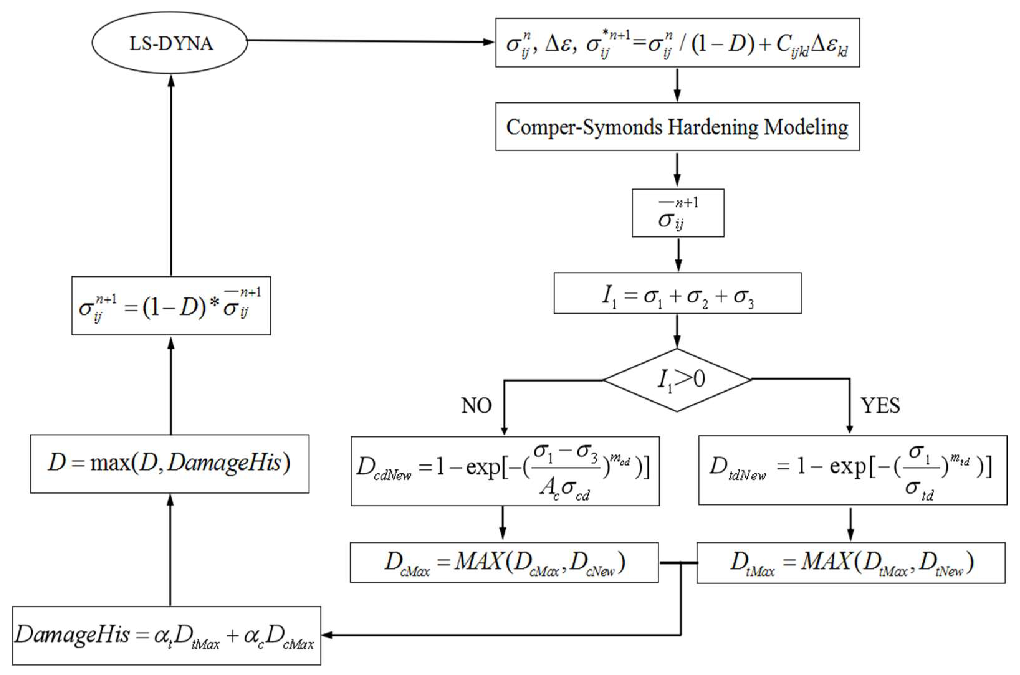
3. Numerical Algorithm of Elastic-Plastic Damage Coupled Model
The proposed elastic-plastic damage coupled model of rock was implemented into the software LS-DYNA as a user-defined material model [23], shown in Figure 1.
Figure 1.
Coupling between Cowper–Symonds hardening model and proposed damage model.
In Figure 1, is effective stress tensor; is trial effective stress tensor; , are stress tensor with damage; is elastic tensor; is strain increment; is tension damage degree rock micro-body (0 < < 1).
The coupling process between the Cowper–Symonds hardening model and the proposed damage model (shown in Figure 1) may be summarized as follows.
Step 1 Calculate the effective stress tensor at by Equation (22).
Step 2 Calculate the trial effective stress tensor at by Equation (23).
Step 3 Judge whether or not to yield by the given yield condition with Equation (24).
where is current yield stress; is trial effective stress.
If , the rock is still in the elastic deformation zone. At this time, the trial strain is equal to the real strain, . Here, is deviatoric stress tensor; is trial deviatoric stress tensor, and we may go to Step 2 and calculate .
If , the material is in plastic state, and plastic strain should be modified by Equation (25).
where , are effective plastic deformation; is effective plastic strain increment; is current yield stress; is the shear modulus.
Meanwhile, proportionally reduce the deviator stress using Equation (26) and make it return to the yield surface.
Step 4 Calculate the effective stress at by Equation (27).
where , is the bulk modulus of elasticity, is the volume of element at , is the volume of element at the original time; is artificial volume viscous damping; is Kronecker delta symbol.
Step 5 Calculate the current damage weightings ( and ) by Equation (21), and the current damage degree by Equation (20). Comparing the current damage degree with the previous damage degrees, the maximum damage degree may be obtained till the current step.
Step 6 Calculate the nominal stress at by Equation (28).
4. Validation of the Availability of Proposed Model
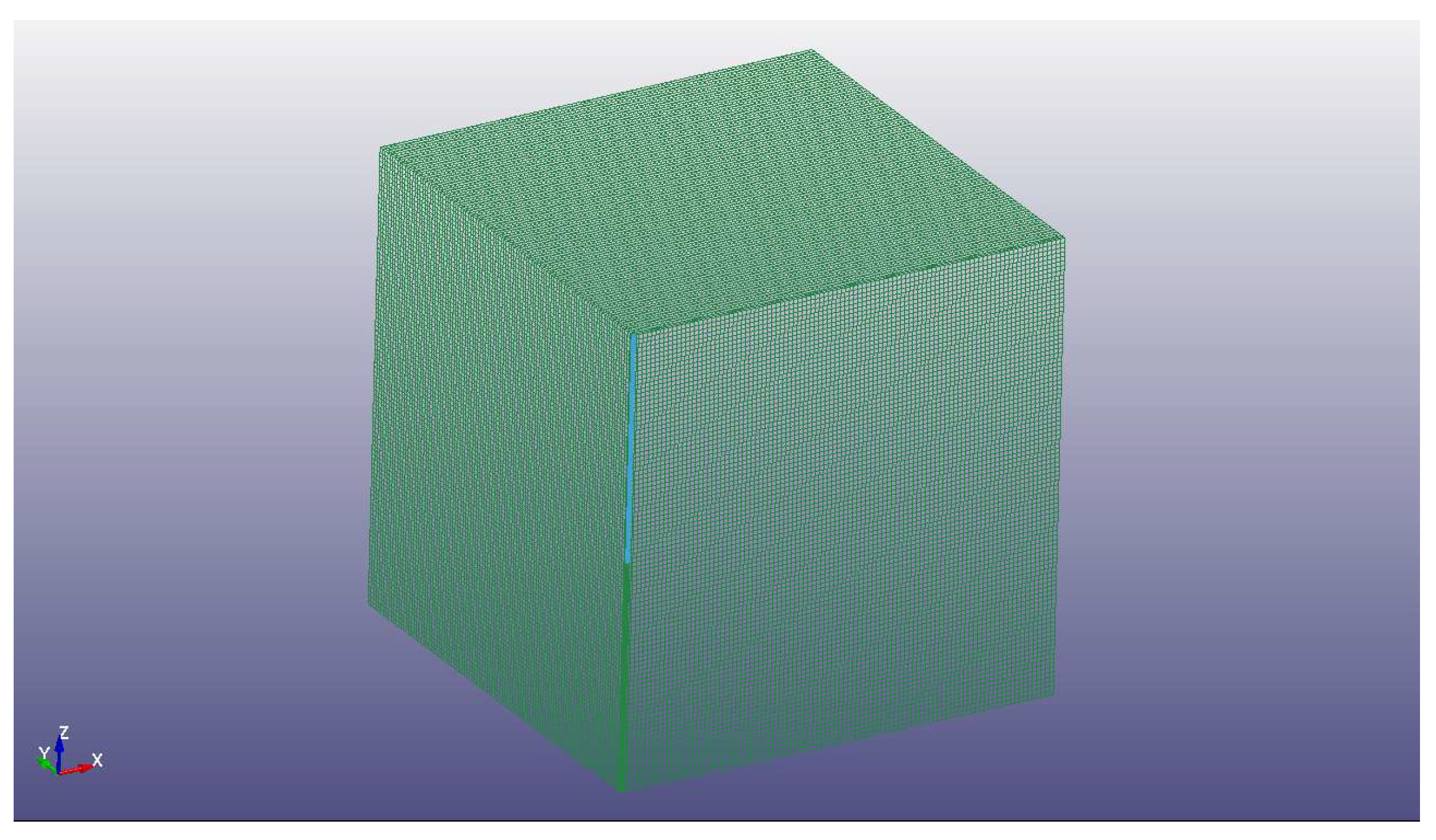
4.1. Numerical Simulation of Single-Column Explosives Blasting Test
The numerical simulation of the single-column explosive blasting test was implemented to verify the availability of the proposed constitutive model.
The model with the length, the width and the height all 4.0 m is established to simulate the single-column explosive blasting test (Figure 2). The upper surface of the model along the Z direction is a free surface, and other surfaces of the model are non-reflective. The parameters of custom constitutive material are listed in Table 1.
Figure 2.
Single-column explosives blasting damage test model.
Table 1.
Parameters of custom constitutive material.
In Figure 2, the origin (0, 0, 0) of the coordinate system is the top of the charge hole. The radii of the charge hole are 42 mm, and the charging length in the hole is 2.0 m. The explosives are detonated at the bottom of the borehole.
The high-energy rock explosive model embedded in LS-DYNA, *MAT_HIGH_EXPLOSIVE_BURN, determines the relationship between the detonation pressure and the volume variation of explosive after the explosions with the JWL state equation [23]. The JWL state equation (see Equation (29)) was proposed by Lee based on Jones and Wilkins’s work in 1965.
where is the pressure of detonation products; , , , and are parameters of JWL equation of state; is relative volume; is the specific internal energy of detonation products.
The main parameters of explosive in the single-column explosives blasting test are listed in Table 2.
Table 2.
Main parameters of the explosives in the explosive blasting test.
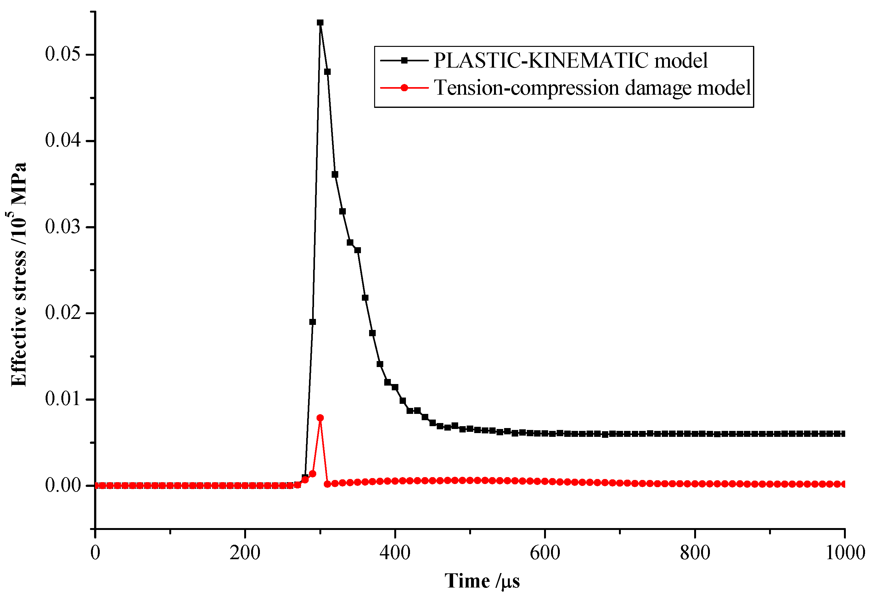
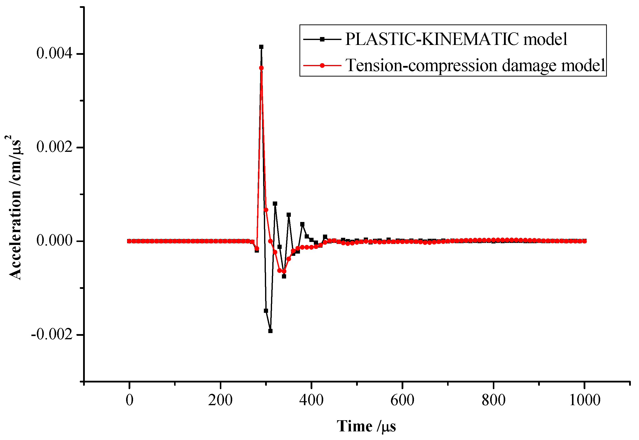
4.2. Analysis of Dynamic Variable Characteristics
We selected Monitoring points (0, 0, 0) and 2 (4.0, 0, 0) to analyze the characteristics of dynamic variables in the single-column explosives blasting test.
From Figure 3 and Figure 4, we note that the overall variation trend of effective stress obtained from the proposed damage model (tension-compression damage model) is consistent with that from the PLASTIC-KINEMATIC model. The peak of effective stress obtained using the proposed damage model is 1GPa at Monitoring point 1, which is 0.2 times the peak obtained using the PLSTIC-KINEMATIC model. The peak of effective stress obtained using the proposed damage model is 1.7 MPa at Monitoring point 2, which is 0.8 times the peak obtained using the PLSTIC-KINEMATIC model. Meanwhile, we noted that the effective stress decreases as the distance from the center of the explosion increases. The blasting dynamic effect can be neglected over 4 m away from the center of the explosion.
Figure 3.
Effective stress-time curves for monitoring point 1.
Figure 4.
Effective stress-time curves for monitoring point 2.
From Figure 5 and Figure 6, we note that the overall variation trend of acceleration obtained using the proposed damage model is basically consistent with that obtained using the PLASTIC-KINEMATIC model, but the acceleration values obtained using the proposed damage model during about 150 µs after the peak of acceleration is some different from that obtained using the PLASTIC-KINEMATIC model (Figure 5).
Figure 5.
Acceleration–time curves for monitoring point 1.
Figure 6.
Acceleration–time curves for monitoring point 2.
From Figure 7 and Figure 8, we note that the overall variation trend of velocity obtained using the proposed damage model is basically consistent with that obtained using the PLASTIC-KINEMATIC model, but after the peak of velocity, the velocity obtained using the proposed damage model is some different from that obtained using the PLASTIC-KINEMATIC model (Figure 7).
Figure 7.
Velocity–time curves for monitoring point 1.
Figure 8.
Velocity–time curves for monitoring point 2.
From Figure 9, we note that since monitoring point 1 is located near the blasting zone, the damage degree at monitoring point 1 reaches 1.0 at about 300 μs after the detonation at the bottom of the explosive. From Figure 10, we note that since monitoring point 2 is away from the blasting area, after the detonation, the rock goes into the damage state at about 850 μs and then reaches the maximum damage value of 0.001 at about 950 μs; the blasting damage of rock at above four meters away from the blasting center is rare.
Figure 9.
Damage degree–time curves for monitoring point 1.
Figure 10.
Damage degree–time curves for monitoring point 2.
4.3. Blasting Damage Evolution Law of Slot Cavity
From Figure 11, we note that after detonating at the borehole bottom, the blasting damage of rock spreads from the bottom to the free surface and reaches the peak instantaneous near the detonating zone; the blasting damage range of rock extends to the free surface at t = 400 µs, and the funnel of blasting damage is basically formed at t = 600 µs; during 200 µs after t = 600 µs, the shape of the blasting damage funnel remains basically unchanged, and the damage scope is further expanded. When the damage degree of rock is 0.2, we noted from Figure 11e that the damage depth is 1.368 m obtained by using the proposed model, which indicates a good agreement with that (1.31 m) of [6,11].
Figure 11.
Blasting damage evolution law of groove-cavity in plane y = 0. (a) t =0 µs. (b) t = 200 µs. (c) t = 400 µs. (d) t = 600 µs. (e) t = 800 µs.
From Figure 12, we note that there is no blasting damage near the free surface within 200 µs after blasting at the bottom of the borehole; the blasting stress waves reach the free surface, and the damage zone generates near the free surface at t = 400 µs. Rock blasting damage zone continuously extends after t = 400 µs. The shape of rock blasting damage zone remains basically unchanged after t = 800 µs and ultimately reaches a stable state.
Figure 12.
Blasting damage evolution law of groove-cavity in plane z = 0. (a) t = 0 µs. (b) t = 200 µs. (c) t = 400 µs. (d) t = 600 µs. (e) t = 800 µs. (f) t = 1000 µs.
5. Case Study
Taking the tunnel of Shenzhen’s Metro Line 11, China, as an example, the surrounding-rock damages of tunnel under blasting construction were analyzed using the proposed model. The tunnel was excavated using the drill-blasting method.
5.1. Blasting Damage Simulation of Surrounding Rock with Six Slot Bores
The model with the length, the width and the height all 4.0 m was established using LS-DYNA3D to simulate the blasting damage of surrounding rock with six straight slotting bores (see Figure 13).
Figure 13.
Geometry model schematic diagram with eight straight slotting bores.
We investigate the generating process of slot cavity and the blasting damage law of surrounding rock using the proposed model, Lagrange algorithm and co-node algorithm. Explosive elements and rock elements are directly with point contact. The absorbing boundary conditions are used for the lateral and bottom of the model. The front of the model (Plane XY) is a free surface, and other surfaces of the model are non-reflective.
The blasting bore inside rock mass is a complete cylinder with a diameter of 42 mm and a depth of 2 m. The grids surrounding explosive products were refined.
The explosives length of every blasting bore is 2.0 m. The stemming length of every blasting bore is 0 m. The bores in the model are all filled by the explosives and are detonated beginning from the bottom of the blasting bores at the same time.
The main parameter values of explosives were the same as those in Table 2. The main physical and mechanical parameter values of surrounding rock were listed in Table 3.
Table 3.
Main physical and mechanical parameters of surrounding rock.
5.2. Results
From Figure 14 and Figure 15, we note that the blasting damage funnel is basically formed about three milliseconds after detonating.

Figure 14.
Blasting damage evolution law of surrounding rock at the bottom of blasting bore (Plane z = −2.0 m). (a) t = 0.1 ms. (b) t = 0.5 ms. (c) t = 1.5 ms. (d) t = 3.0 ms.
Figure 15.
Blasting damage evolution law of surrounding rock along the longitudinal direction of tunnel (Plane y = 0 m). (a) t = 0.1 ms. (b) t = 0.5 ms. (c) t = 1.5 ms. (d) t = 3.0 ms.
From Figure 14, we note that blasting damage can be divided into three stages in the process of slot-blasting as follows: at the initial stage, the damage to surrounding rock generates around every blasting bore (Figure 14a); at the second stage, the damage zone of surrounding rock adjacent blasting bores is connected (Figure 14b,c); at the third stage, the surrounding rock damage spreads continuously to the periphery along with the blasting bores until a complete damage zone is generated (Figure 14d).
The blasting stress wave reaches the non-reflective boundary about one millisecond after detonating. Rock damage is caused by stress waves reflected from the non-reflective boundary generated at about one-half millisecond after detonating. With the appearance of the reflective stress wave, the damage develops around the original damage zone.
The calculation results are used to guide the slotting-blasting of the subway tunnel. It is proved by practice that the numerical simulation results can basically reflect the effect of tunnel blasting.
5.3. Discussion
This paper mainly studies the blasting damage mechanism of rock. There is a rock dilatation effect under cutting blasting. For heterogeneous rocks, there is usually the low-stress-damage coupling phenomenon [15]. It is necessary to take into account the growth of existing fractures and the formation of fractures under cutting blasting. Deep tunnels often have an effect on groundwater, so the influence of groundwater on the seepage-stress-damage coupling action of tunnel cutting blasting generally cannot be ignored [16]. We will be further studied these above problems.
In this paper, we developed the tensile-compression weighted damage model only using the comprehensive damage degree, and the tensile damage and the compression damage are not considered separately in the model algorithm. We will consider it in the next study.
6. Conclusions
- The proposed weighted damage calculation method may measure the coupling effect of tension damage and compression damage under blasting load.
- Compared with the calculation results using the classical PLASTIC-KINEMATIC model, the proposed model of rock blasting damage may better simulate the variation laws of effective stress, acceleration and velocity with time under blasting load.
- It is available that the proposed model of rock blasting damage is used to investigate the blasting damage evolution law of rock in the process of slotting-blasting.
- The engineering application shows that using the proposed model of rock blasting damage may investigate the generating process of slot cavity and the damage law of surrounding rock in the slotting-blasting construction of rock tunnel.
Author Contributions
J.X.: conceptualization and constitutive model development, writing—review and editing; Z.W.: numerical simulation and analysis, writing—original draft preparation; G.R.: data curation, investigation. All authors have read and agreed to the published version of the manuscript.
Funding
This research was funded by the Science and Technology Project of China Railway 20th Bureau Group Co., Ltd., grant number: no, China Postdoctoral Science Foundation, grant number 20060390165, and Shanghai Postdoctoral Science Foundation, grant number 06R214152.
Institutional Review Board Statement
Not applicable.
Informed Consent Statement
Not applicable.
Data Availability Statement
Data are contained within this article.
Conflicts of Interest
The authors declare no conflict of interest.
References
- Li, X.P.; Chen, J.; Li, Y.H.; Dai, Y.F. Study of criterion and damage zone induced by excavation blasting of underground power-house of Xiluodu hydropower station. Chin. J. Rock Mech. Eng. 2010, 29, 2042–2049. [Google Scholar]
- Hu, Y.G.; Lu, W.B.; Chen, M.; Yan, P.; Zhou, C.B. Comparison and improvement of blasting damage models for rock. Rock Soil Mech. 2012, 33, 3278–3284. [Google Scholar]
- Lu, W.; Yang, J.; Chen, M.; Zhou, C. Mechanism and equivalent numerical simulation of transient release of excavation load for deep tunnel. Chin. J. Rock Mech. Eng. 2011, 30, 1089–1096. [Google Scholar]
- Yang, R.; Bawden, W.F.; Katsabanis, P.D. A new constitutive model for blast damage. Int. J. Rock Mech. Min. Geomech. Abstr. 1996, 33, 245–254. [Google Scholar] [CrossRef]
- Liu, L.; Katsabanis, P.D. Development of a continuum damage model for blasting analysis. Int. J. Rock Mech. Min. 1997, 34, 217–231. [Google Scholar] [CrossRef]
- Deng, X.F.; Zhu, J.B.; Chen, S.G.; Zhao, Z.Y.; Zhou, Y.X.; Zhao, J. Numerical study on tunnel damage subject to blast-induced shock wave in jointed rock masses. Tunn. Undergr. Space Technol. 2014, 43, 88–100. [Google Scholar] [CrossRef]
- Deng, X.F.; Chen, S.G.; Zhu, J.B.; Zhou, Y.X.; Zhao, Z.Y.; Zhao, J. UDEC-Autodyn hybrid modeling of a large-scale underground explosion test. Rock Mech. Rock Eng. 2015, 48, 737–747. [Google Scholar] [CrossRef]
- Chen, J.H.; Zhang, J.S.; Li, X.P. Model of rock blasting-induced damage considering integrity of rock mass and its application. Rock Soil Mech. 2016, 38, 857–866. [Google Scholar]
- Xie, L.X.; Lu, W.B.; Zhang, Q.B.; Jiang, Q.H.; Wang, G.H.; Zhao, J. Damage evolution mechanisms of rock in deep tunnels induced by cut blasting. Tunn. Undergr. Space Technol. 2016, 58, 257–270. [Google Scholar] [CrossRef]
- Zhu, J.B.; Li, Y.S.; Wu, S.Y.; Zhang, R.; Ren, L. Decoupled explosion in an underground opening and dynamic responses of surrounding rock masses and structures and induced ground motions: A FEM-DEM numerical study. Tunn. Undergr. Space Technol. 2018, 82, 442–454. [Google Scholar] [CrossRef]
- Wang, F.; Tu, S.; Yuan, Y.; Feng, Y.F.; Chen, F.; Tu, H.S. Deep-Hole pre-split blasting mechanism and its application for controlled roof caving in shallow depth seams. Int. J. Rock Mech. Min. 2013, 64, 112–121. [Google Scholar] [CrossRef]
- Yang, J.H.; Lu, W.B.; Hu, Y.G.; Chen, M.; Yan, P. Numerical simulation of rock mass damage evolution during deep-buried tunnel excavation by drill and blast. Rock Mech. Rock Eng. 2015, 48, 2045–2059. [Google Scholar] [CrossRef]
- Tang, C. Numerical simulation of progressive rock failure and associated seismicity. Int. J. Rock Mech. Min. 1997, 34, 249–261. [Google Scholar] [CrossRef]
- Svedberg, T.; Runesson, K. An adaptive finite element algorithm for gradient theory of plasticity with coupling to damage. Int. J. Solids Struct. 2000, 37, 7481–7499. [Google Scholar] [CrossRef]
- Tang, C.A.; Tham, L.G.; Lee, P.K.K.; Yang, T.H.; Li, L.C. Coupled analysis of flow, stress and damage (FSD) in rock failure. Int. J. Rock. Mech. Min. 2002, 39, 477–489. [Google Scholar] [CrossRef]
- Cao, W.G.; Zhang, S.; Zhao, M.H. Study on statistical damage constitutive model of rock based on new definition of damage. Rock Soil Mech. 2006, 27, 41–46. [Google Scholar]
- Jiang, A.N.; Zheng, S.; Wang, S.Y. Stress-Seepage-Damage coupling modelling method for tunnel in rich water region. Eng. Comput. 2020, 37, 2659–2683. [Google Scholar] [CrossRef]
- Grady, D.E.; Kipp, M.E. Continuum modeling of explosive fracture in oil shale. Int. J. Rock Mech. Min. 1980, 17, 147–157. [Google Scholar] [CrossRef]
- Zhu, J.B.; Deng, X.F.; Zhao, X.B.; Zhao, J. A numerical study on wave transmission across multiple intersecting joint sets in rock masses with UDEC. Rock Mech. Rock Eng. 2013, 46, 1429–1442. [Google Scholar] [CrossRef]
- Liu, C.; Lu, Y.; Xia, B.; Yu, P. Directional fracturing by slotting-blasting-caused stress wave form changes. Int. J. Impact Eng. 2019, 129, 141–151. [Google Scholar] [CrossRef]
- Li, Q.; Gao, Z.H.; Yu, Q.; Huang, C.; Wang, K.; Xu, W.L. Effect of explosive stress waves on the crack propagation in the defective medium using strain gauge method. KSCE J. Civ. Eng. 2022, 26, 2780–2788. [Google Scholar] [CrossRef]
- Cowper, G.R.; Symonds, P.S. Strain Hardening and Strain Rate Effects in the Impact Loading of Cantilever Beams; Brown University: Providence, RI, USA, 1958. [Google Scholar]
- Lewis, B.A. Manual for LS-DYNA Soil Material Model 143; US Federal Highway Administration: Washington, DC, USA, 2014.
Publisher’s Note: MDPI stays neutral with regard to jurisdictional claims in published maps and institutional affiliations. |
© 2022 by the authors. Licensee MDPI, Basel, Switzerland. This article is an open access article distributed under the terms and conditions of the Creative Commons Attribution (CC BY) license (https://creativecommons.org/licenses/by/4.0/).