Featured Application
The proposed dynamic modeling and control method considering joint friction could be applied not only to the trajectory control of the hip joint simulator, but also to other parallel and series manipulators with high-loads.
Abstract
To overcome the bearing capacity deficiencies of traditional serial hip joint simulators, complex trajectory simulation, among others, as well as a parallel manipulator with two pairs of artificial hip joints and two moving platforms are proposed. The movements and driving forces of the parallel manipulator under the required motion and loading are studied to provide a basis for further research. In this study, the modeling and analysis of inverse kinematics and dynamics for a parallel manipulator with joint friction are derived. In the inverse kinematic model, kinematic relationships between the linear module slider and the moving platform are established, and expressions for the slider are deduced. Subsequently, by analyzing the frictional forces of the artificial hip joint and thrust ball bearing, a rigid body dynamics model of the parallel manipulator with joint friction is established, which is subsequently decomposed into four driving torques associated with the moving platform, joint lever, slider, and screw. Finally, the difference in the kinematic performance between the two moving platforms is analyzed using numerical simulations and experiments, and the accuracy of the established model is verified.
1. Introduction
Hip replacement surgery is commonly used to treat pain and disability due to cartilage injury, synovial fluid reduction, and osteoarthritis [1,2]. However, debris from friction on joint contact surfaces enters circulation, and many patients require revision surgery after 15–20 years [3]. Therefore, it is necessary to examine the friction and wear characteristics of artificial hip joints using in vitro simulation methods.
Simulators of the artificial hip joint must simulate the motion and load changes of the human hip joint simultaneously, and most existing simulators often use a serial manipulator as the core module [4]. Groves et al. [3] developed a pendulum friction simulator that enables the acetabulum and femoral head to maintain the correct center of rotation and evaluated the efficacy of the simulation system by testing the natural porcine hip joint and artificial hip joint. Daou et al. [5] developed a serial manipulator to test the biomechanics of hip joint specimens, and reduced the hip joint clamping error by installing force sensors. Nečas et al. [6] used a pendulum simulator to analyze the effect of the texturing of the ultrahigh-molecular-weight polyethylene acetabular cup on tribological properties, and the results showed that surface texturing could improve the stability of the friction of the artificial hip joints. Although serial manipulators can partially simulate the kinematic and dynamic performance of the human hip joint, they are deficient in terms of repeatability, comparative accuracy, complex trajectory simulation, and dynamic loading [7,8]. Moreover, a serial hip joint simulator can test only a single type of joint motion. Generally, parallel manipulators with a closed-chain structure consisting of multiple kinematic chains have the advantages of high precision [9] and high load capacity [10], are widely used in medicine engineering [11] and precision support [12], and are being developed to achieve high speeds and more reconfigurability [13]. The application of parallel manipulators to artificial hip joint testing provides precise trajectories and facilitates carrying higher loads. Wang et al. [14,15] designed a 3SPS+1PS parallel manipulator with satisfactory performance in simulating the kinematics, dynamics, and load changes of the hip joint. In the ISO 14242-1:2014(E) standard, a complete test requires the completion of 5 × 10⁶ cycles. At present, most of the existing hip joint simulators have only one moving platform, resulting in lower efficiency in many practical applications. Therefore, it is a great prospect to design a parallel manipulator that can be used for the friction and wear test of various size of hip joints and can perform the test on two hip joints simultaneously.
Generally, kinematic analysis and dynamic modeling are the basis for structural optimization, performance analysis, and controller design of a parallel manipulator. Scholars have performed many studies on lower-mobility parallel mechanisms and achieved significant results. Chong et al. [16] proposed a 1T2R parallel manipulator dynamic performance and acceleration capability evaluation method that discussed the dynamic isotropic performance and area of the feasible acceleration region under the influence of velocity, external load, and gravity. Huo et al. [17] established a dynamics model of a 2 DOF overconstrained tracking parallel manipulator based on the principle of virtual work, and the effects of inertia and friction are considered in the identification to achieve a balance between accuracy and efficiency. Müller [18,19] proposed a kinematic modeling method for parallel manipulators with a simple topology to flexibly establish motion equations in task space coordinates and end-effector coordinates. According to the ISO14242 standard, the high speed and acceleration of the parallel manipulator during the artificial hip joint wear test lead to the need for the servo motor to change speed frequently, so the control strategy based on kinematic parameters is difficult to maintain the accuracy of the parallel manipulator. Therefore, it is important to establish a dynamics model that is close to the actual dynamics characteristics of the parallel manipulator.
With an increase in speed, the joint friction effect becomes significant [20,21], and friction effect plays an important role in controlling and tracking the accuracy of the parallel manipulator [22]. Unsworth’s [23] experiments with artificial hip joint friction measurements using the Durham friction simulator showed that hip joint friction under high loads cannot be ignored. Yuan et al. [24] proposed a parallel manipulator decomposition modeling method, which projected the force of the moving platform in the workspace into the joint space to calculate the normal force of the sliding plane of the driving joint and then obtained the friction force. Wu et al. [25] proposed a joint friction solution method that subtracts the inertial parts from the joint torque, and the reduction of dynamic model accuracy due to the friction model deviation can be avoided. Farhat et al. [26] solved the discontinuity problem of the friction model of a 3-DOF parallel manipulator by dividing the self-interval, calculating the friction force in the viscous phase, and enhancing stability. Parallel manipulators are subjected to cyclically varying loads during friction and wear testing, resulting in significant friction that is difficult to eliminate directly through error compensation. Therefore, with regard to the dynamic analysis of parallel mechanisms, the time-varying characteristics of artificial hip joint friction cannot be ignored.
In this study, to overcome the shortcomings of series hip joint simulators with regard to their bearing capacity, trajectory simulation, accuracy, etc., and to remedy the lower working efficiency deficiencies using a single moving platform, and considering the cost and dimensions of the assembly, a 2(3PUS+S) parallel manipulator with two pairs of artificial hip joints and two moving platforms is proposed, which can simultaneously conduct friction and wear tests for two pairs of artificial hip joints. To lay the foundation for further research, the movements and driving forces of the parallel manipulator under the required motion are studied. First, the inverse kinematics for the parallel manipulator is modeled, and the kinematic relationships between the linear module slider and the moving platform are established. Second, the driving torque of each component is analyzed separately. Combined with the Coulomb friction model of artificial joints and thrust ball bearings, a rigid-body dynamics model of a parallel manipulator with joint friction is established. Finally, numerical simulations and experiments are conducted to analyze the kinematic differences between the two moving platforms under the required motion and verify the accuracy of the kinematic and dynamical models.
2. Mechanism and Establishing the Coordinates
For a parallel manipulator with multiple moving platforms driven by the same set of actuators for achieving the same motion, the positions of the moving platforms should be arranged symmetrically or in parallel to each other or in the same plane. Considering the strengths and weaknesses of the obtained configurations, two 3PUS+S-type parallel manipulators were designed as the core module of the parallel manipulator, and the two moving platforms were arranged parallel to each other. Theoretically, both the platforms perform the same action.
As shown in Figure 1, the 2(3PUS+S) parallel hip joint simulator comprises two pairs of artificial hip joints, two moving platforms (m1 and m2), one base platform (B), three joint levers, three linear modules (LNi), and one intermediate branch chain. Three active linear modules and one intermediate branch chain were rigidly fixed to the base platform. In this paper, P refers to the prismatic joints composed of the lead screw and nut, U refer to the universal joints installed on the linear module slider, and S refer to the spherical joints installed on the moving platform with a fixed-length joint lever. The figure was shown in our previous paper [27].
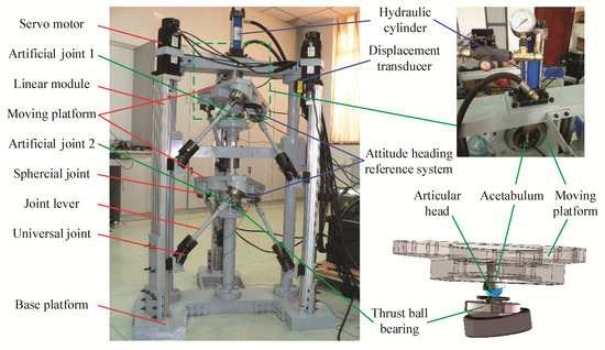
Figure 1.
2(3PUS+S) parallel manipulator.
Three surrounding branch chain PUS were placed symmetrically at 120° intervals, with the intermediate branch chain S in the center of the base platform. Two fixed distance sliders were installed on each linear module. The joint lever was designed to connect the slider and moving platform. The motion of the servo motor was transmitted to the moving platform through the linear module and the joint lever. The intermediate branch chain was connected to the moving platform through the spherical joint S.
The intermediate branch chain, which is divided into two sections to install artificial hip joints, is a passive branch chain. The articular head was assembled on the moving platform, and their rotation centers were coincided. The acetabulum was fixed, and the moving platform could achieve rotational motion with the artificial hip joint as the center. The articular head of joint 2 was assembled on the base platform through a thrust ball bearing and a section of the intermediate branch chain, and the articular head of joint 1 was connected to the acetabulum of joint 2 through a thrust ball bearing and ball spline shaft. The hydraulic system was connected to the acetabulum of joint 1 through a guide rail and pressure sensor. A loading force was applied to artificial joint 1 and then transferred to artificial joint 2 through the ball spline shaft. A spring equal to the gravity of moving platform m1 was installed in the ball spline, and the height of the artificial joint remained constant during the operation.
In Figure 2, Ai (i = 1, 2, 3) is the intersection of the linear module lead screw and base platform, and ci is the projection point of b1i and b2i on line OAi. Let O be a center point fixed in the triangle A1A2A3 with a circumscribed circle radius E. The absolute reference frames O-XYZ (green) are attached at the point O with the Z-axis vertically upward, and the X-axis is perpendicular to A1A2 and points away from OA3. Similarly, aji (j = 1, 2) and bji are the intersection points of the rotation axes of spherical and universal joints, respectively. The relative reference frames oj-xjyjzj (red) are attached at the center point oj of triangle aj1aj2aj3 with a circumscribed circle radius e. The yj-axis crosses point aj2, the zj-axis is perpendicular to triangle aj1aj2aj3 and is directed to the hydraulic system.
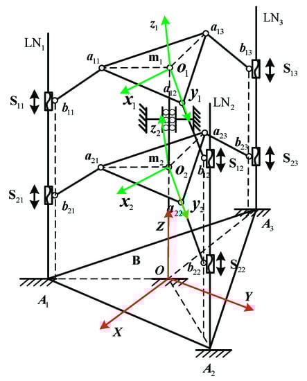
Figure 2.
2(3PUS+S) parallel manipulator topological structure.
For most serial hip joint simulators, the cantilever structure is predominantly used as the loading part, which causes angle errors in the forced direction of the hip joint. Simultaneously, maintaining the equilibrium between the loading force and the bearing device is generally complicated, as a serial hip joint simulator can test only a single type of joint motion. However, the motions of the actual hip joint vary during different actions such as walking and jogging. The loading force is generated directly by a hydraulic cylinder, and the direction passes through the rotation center of the moving platform and can be directly balanced by the intermediate branch chain. The dynamic characteristics of the loading force depend entirely on the hydraulic cylinder performance. In the design process of a parallel manipulator, there are two key points: motion simulation and implementation of dynamic loading force. Motion simulation is the most important aspect. For the proposed 2(3PUS+S) parallel manipulator, the dynamic loading force was implemented using a hydraulic cylinder, and this study is mainly focused on the motion simulation of the recommended curves.
3. Inverse Kinematics
3.1. Position Analysis
The clearance and elastic deformation of the joints and components are ignored in the modeling; therefore, there are no practical differences (from a modeling and analysis standpoint) between a single and multi-platform manipulator. The three PUS modules have the same kinematic structure, and the vector relationship of one closed kinematic chain is shown in Figure 3.
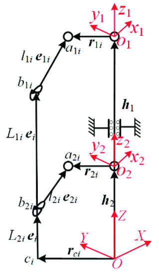
Figure 3.
Vector diagram of a closed kinematic chain.
During the working process, the frames of the moving platform are defined by the roll, pitch, and yaw angle parameters. The orientation of the moving platforms mj at any time can be described as qj = [αj, βj, γj]T. Let ei and eji be unit vectors along b2ib1i and bjiaji. Let hj, rji and rci be the position vector along Ooj, ojaji and Oci in O-XYZ. From Figure 3, we can express the closed kinematic chain as follows:
Here, Lji is the distance between slider Sji and point ci; lji is the length of joint lever ajibji; and lji= ll is a constant.
Based on Equation (1), according to the assembly scheme of the parallel manipulator, the displacement of Sji can be represented as follows:
where rjix, rjiy, rjiz are the direction vectors for the decomposition of rji, and rcix, rciy, rciz are the direction vectors for the decomposition of rci.
3.2. Velocity Analysis
The hypothesis is that and are the angular velocity and angular acceleration of the moving platform mj, respectively. The translational velocity of slider Sji is obtained by finding the first-order derivative of Equation (1) with respect to time.
where , and is the translational speed of the slider Sji; , , , .
The rotational angular velocity and joint lever center velocity of bjiaji can be obtained as follows:
where and are antisymmetric matrices corresponding to and , respectively.
3.3. Acceleration Analysis
The translational acceleration of slider Sji is obtained by finding the second order derivative with respect to time for Equation (1).
where ,, , .
The rotational angular acceleration and acceleration of the joint lever center of bjiaji can be written as follows:
Singularities occur when the Jacobian matrices are and . The first occurs when the joint levers are located in the horizontal plane, and the second occurs when all projections of the joint lever on the horizontal plane cross the center of the platform.
4. Inverse Rigid-Body Dynamics
If joint friction is ignored, the D’Alembert principle is employed to calculate the resultant forces as well as the moments loaded at the center of the components. For the moving platform mj, the equations can be expressed as follows:
where and , respectively, denote the applied forces and moments of the moving platform mj and mm and Im denote the mass and inertia of the moving platform mj, respectively.
The summation of the applied and inertial forces, as well as the moments loaded on the joint lever bjiaji can be expressed as follows:
where Rji denotes the rotation matrix of the body-fixed coordinate system of the joint lever bjiaji corresponding to O-XYZ, and ml and Il are the mass and inertia of the joint lever bjiaji, respectively.
The applied and inertial forces loaded at the slider Sji can be obtained as follows:
where mL denotes the mass of slider Sji.
Supposing is the drive-torque output from the motor, the moment of inertia of the lead screw on the linear module LNi can be expressed as follows:
where and are the rotary inertia and lead of the lead screw.
The sum of the virtual work of the active forces and moments, as well as the inertial forces and moments on the parallel manipulator, must be zero, so the following expression can be obtained:
where is the sum friction moment of the artificial hip joint and the thrust ball bearing; is the relative angular velocity of the spherical joint aji; and are the friction moments of the spherical joint aji and the universal joint bji, respectively; , , and is the friction of the slider Sji; , is the angular velocity of the lead screw of linear modules LNi, , , and is the friction moment of the lead screw.
According to the relative motion between the joint lever and moving platform, can be represented as
where and simple notations, with the compact notation and .
Considering joint friction, the input torques driven by the linear module motor can be expressed as follows:
where .
To signify the contribution of each part to the input torques driven by the linear module motor, the driving torques were divided into four parts. The four parts are described as the driving torque transformed into the inertia of the moving platform , the driving torque transformed into the gravity and inertia of the joint lever , the driving torque transformed into the gravity and inertia of the slider , and the driving torque transformed into the inertia of the screw .
5. Simulation and Experiment Analysis
5.1. Kinematics Simulation
To investigate the control behavior of hip joint prosthesis motion, experiments were carried out on ISO14242-1:2014(E), in which the spin axes of the X-axis, Y-axis, and Z-axis were 18°–25°, −4°–7°, and −10°–2°, respectively. To illustrate the role of the wear test machines, the control input is shown in Figure 4.
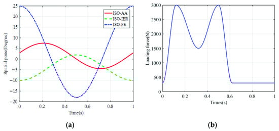
Figure 4.
Loading and displacement parameters for wear-testing machines. (a) Motion curves; (b) Loading force.
Based on a preliminary parameter optimization considering the mounting dimension and maximal rotary angle of the spherical joint, maximum stroke and driving force of the linear module, and orientation working space of the moving platform, the main structural parameters of the parallel manipulator are obtained, as listed in Table 1.

Table 1.
Main structure parameters of the parallel manipulator.
The control strategy of the PD controller based on the workspace is shown in Figure 5, and the driving force matrix of the active branch chains can be expressed as follows:
where is the attitude angle error of the moving platform.
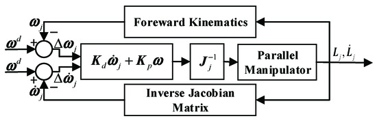
Figure 5.
Block diagram of the PD controller.
To avoid singular positions in the operation process of the parallel manipulator, the initial position is obtained from the motion curves in Figure 6b at zero after a 30° rotation around the Z-axis. The displacements, velocities, and accelerations of the sliders were simulated as shown in Figure 6.
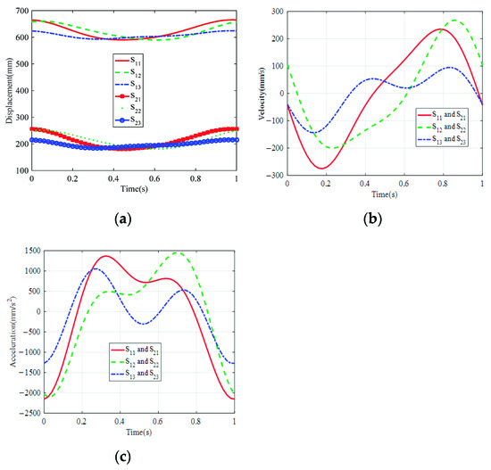
Figure 6.
Motion curves of the slider. (a) Displacement; (b) Velocity; (c) Acceleration.
As shown in Figure 6, the curves of the displacements, velocities, and accelerations of the sliders were smooth, and there were no rush points. The maximum displacements of sliders S11, S12, and S13, corresponding to the moving platform m1 were 665.58 mm, 660.47 mm, and 624.42 mm, respectively. The maximum displacements of sliders S21, S22 and S23 corresponding to moving platform m2 were 256.58 mm, 251.47 mm, and 215.42 mm, respectively. Sliders S11 and S21, S12, and S22, and S13 and S23 were installed on the same lead screws and the corresponding maximum velocities and accelerations are 275.15 mm/s, 267.80 mm/s, 143.97 mm/s, and 2152.40 mm/s2, 2100.80 mm/s2, 1270.90 mm/s2, respectively.
With moving platform m2 as the control object and moving platform m1 as the follower, the posture angles were detected by the attitude heading reference system installed on the moving platform. The errors in the output posture angles of the moving platform are shown in Figure 7.
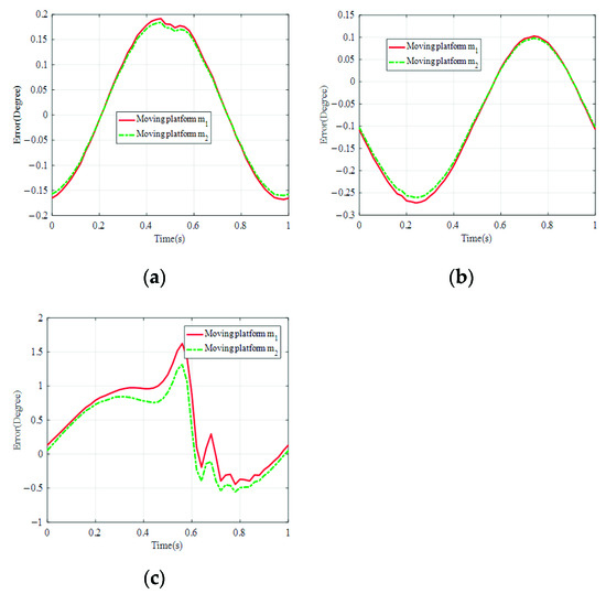
Figure 7.
Errors of the posture angles of the moving platform. (a) AA error; (b) IER error; (c) EE Error.
From Figure 7, it can be observed that the error of the posture angle around the Z-axis was larger than that around the X-axis and Y-axis. In the intermediate branch chain, the position of the rotation center of the moving platform m1 in the absolute reference frames along the Z-axis direction was influenced by the position of the mobile platform m2, and the attitude error of the moving platform m1 was greater than that of the moving platform m2 because of the cumulative effect of the error.
5.2. Dynamics Simulation
Due to the large number of joints in the parallel Manipulator with two moving platforms, the control performance of parallel manipulator was significantly affected by the friction of the motion joints. Especially when the robot was used for the artificial hip joint friction and wear test, the 300 N~3000 N dynamic load was loaded directly on the joint, and the friction at the artificial joint and thrust ball bearing would have a more significant effect.
During the dynamic simulation of the hip joint simulator, only the effect of the frictional force of the intermediate branch chain with higher loading force on the dynamic characteristics of the manipulator is discussed. Subsequently, the Coulomb friction model of the artificial joints and thrust ball bearings is established.
where and denote the radii and friction factors of the hip joint, and and denote the radii and friction factors of the thrust ball bearing, respectively.
The MATLAB software was used to validate the dynamic model of the parallel manipulator. In the manuscript, parts of the virtual prototype are established in the Solidworks software, and the mass and inertia parameters can be obtained, as shown in Table 2.
Table 2.
Mass and inertia parameters of the parallel manipulator.
From the aforementioned analysis, the contributions of each part to the input torques actuated by the motors were obtained, as shown in Figure 8.
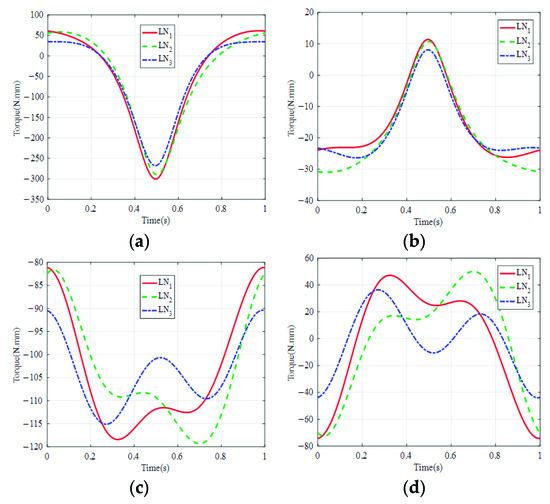
Figure 8.
Contributions of each part to the input torques. (a) Moving platform; (b) Joint lever; (c) Slider; (d) Lead screw.
As shown in Figure 8, in the working process of the parallel manipulator, the maximum driving torques of the three linear modules related to the inertia of the moving platform were 300.18 N·mm, 289.79 N·mm, and 267.69 N·mm, respectively. The maximum driving torques of three linear modules related to the gravity and inertia of the joint lever were 26.22 N·mm, 30.97 N·mm, and 26.38 N·mm, respectively. The maximum driving torques of the three linear modules related to the gravity and inertia of the slider were 118.41 N·mm, 119.30 N·mm, and 115.11 N·mm, respectively. The maximum driving torques of the three linear modules related to the inertia of the lead screw were 74.261 N·mm, 72.69 N·mm, and 44.12 N·mm, respectively. The driving torques of the three linear modules related to the moving platform were greater than those associated with the other parts. The driving torque can be reduced to a certain degree by reducing the masses of the moving platform and slider. The block diagram of the designed augmented PD controller can be seen in Figure 9.
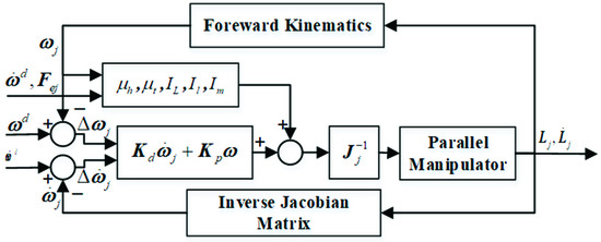
Figure 9.
Block diagram of the augmented PD controller.
The dynamics experiment platform consists of an industrial control computer (IPC), a drive system, a hydraulic loading system, and a data acquisition system. The control and compensation program are programmed by LabVIEW and installed in the IPC. The servo motor is controlled by a motion control card (GTS-400-PV from Goodco) and a servo driver. The hydraulic cylinder is controlled by PLC and the hydraulic system applies the loading force by controlling the opening size of the proportional valve. The data acquisition system consists of an encoder, attitude heading reference system, and pull wire displacement sensor. The structure of the control and data acquisition system is shown in Figure 10.
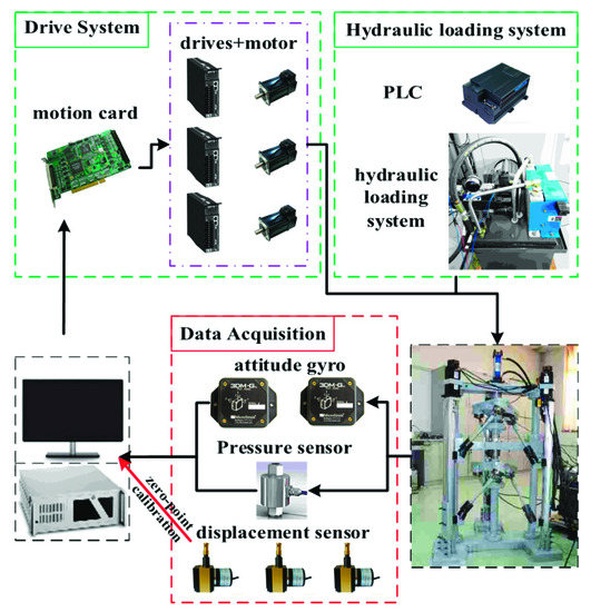
Figure 10.
Control and data acquisition system of the parallel manipulator.
The rotation angle, angular velocity, and angular acceleration of the servo motor are measured directly by the encoder. The attitude of the moving platform is measured by an attitude heading reference system with a single experiment time less than five minutes caused by the zero point drift of the device. Owing to the measurement delay, the pull-wire displacement sensor cannot be used for feedback of the control system, but for calibration of the zero point of the slider.
As observed in Figure 11, the results from the dynamic model and the experiment showed the same trends in their variation. The drive torque of the three linear modules was similar in one cycle, which indicates that the load of the linear modules were balanced. The driving torque was larger at 0.4–0.6 s, with maximum values reached 850 N·mm, 806 N·mm, and 743 N·mm, respectively. Further, there was a large difference in the driving torque at 0 s–0.6 s and 0.6 s–1 s. Combined with Figure 4b, it can be seen that the friction torque of the moving platform was larger at 0 s–0.6 s because of the larger pressure output by the loading system, and the friction torque of the moving platform was smaller at 0.6–1 s because of the smaller and stable pressure output by the loading system.
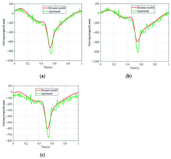
Figure 11.
Torques actuated by the motors. (a) Linear module 1; (b) Linear module 2; (c) Linear module 3.
The difference between the theoretical and actual parameters of the parallel manipulator resulted in errors in the driving torque. The errors of the three linear module drive torque were larger around 0.55 s, and the maximum values reached 158 N·mm, 220 N·mm, and 186 N·mm, respectively, which may be caused by the rotation direction variation of the moving platform. At this point, the hydraulic loading system outputs a larger loading force, and the nonlinear dynamics become significant. Experiments were conducted to verify the correctness of the dynamic model, which demonstrated that the established dynamic model can accurately describe the performance of the parallel manipulator.
6. Conclusions
In this study, a 2(3HUS+S) parallel hip joint simulator with two moving platforms that can be used for simultaneous friction wear tests of two artificial hip joints is proposed. The inverse kinetics of a parallel manipulator were derived, and the rigid-body dynamics of the two moving platforms with joint friction were analyzed. In the inverse kinematic model, the kinematic relationships between the slider of the linear module and the moving platform were established. Accordingly, a PD controller based on the workspace was designed, and small errors in the output posture angles of the moving platform verified the correctness of the derived kinematic model. The right linear module can be selected according to the kinematic and dynamic models.
A dynamic model of a parallel manipulator with joint friction was designed. The contributions of each part to the input torques actuated by the motors of the parallel manipulator were studied, and the results indicated that the driving torques required to actuate the moving platform were greater than those required to actuate the other parts. The driving torque could be reduced by reducing the masses of the moving platform and the slider. The difference between the ideal and actual parameters of the parallel moving platform resulted in errors between the driving torques by the dynamic model and the actual driving torques. The errors were larger around 0.55 s, caused by the rotation direction variation of the moving platform, and the nonlinear dynamics become significant. Realistic kinematic and dynamic analyses of parallel manipulators are the basis for control system design.
Author Contributions
Conceptualization, S.C.; methodology, S.C., Y.P. and G.C.; formal analysis, S.C. and G.C.; writing—original draft preparation, S.C.; writing—review and editing, G.C. and Y.P.; project administration, G.C. All authors have read and agreed to the published version of the manuscript.
Funding
This study was financially supported by the Priority Academic Program Development of Jiangsu Higher Education Institutions and the National Natural Science Foundation of China (Grant No. 91648105).
Institutional Review Board Statement
Not applicable.
Informed Consent Statement
Not applicable.
Data Availability Statement
The simulation and experimental data used to support the findings of this study are available from the corresponding author upon request.
Conflicts of Interest
The authors declare no conflict of interest.
References
- Murray, D.G.; Crown, R.S.; Dickersin, K.; Duncan, P.W.; Epps, C.H.; Ettinger, W.H.; Friedlaender, G.E.; Lane, J.M.; Lemons, J.E.; Lewis, J.L.; et al. Total hip replacement. JAMA-J. Am. Med. Assoc. 1995, 273, 1384–1387. [Google Scholar] [CrossRef]
- Valente, G.; Taddei, F.; Leardini, A.; Benedetti, M.G. Effects of hip abductor strengthening on musculoskeletal loading in hip dysplasia patients after total hip replacement. Appl. Sci. 2021, 11, 2123. [Google Scholar] [CrossRef]
- Groves, D.; Fisher, J.; Williams, S. An in vitro simulation method for the tribological assessment of complete natural hip joints. PLoS ONE 2017, 12, e0184226. [Google Scholar] [CrossRef] [PubMed] [Green Version]
- Goldsmith, M.T.; Rasmussen, M.T.; Lee, T.T.; Trindade, A.C.; LaPrade, R.F.; Philippon, M.J.; Wijdicks, C.A. Validation of a six degree-of-freedom robotic system for hip in vitro biomechanical testing. J. Biomech. 2015, 48, 4093–4100. [Google Scholar] [CrossRef] [PubMed]
- Daou, H.E.; Geoffrey, K.C.; Arkel, R.V.; Jeffers, J.R.; Baena, F.R. Robotic hip joint testing: Development and experimental protocols. Med. Eng. Phys. 2019, 63, 57–62. [Google Scholar] [CrossRef] [PubMed]
- Nečas, D.; Usami, H.; Niimi, T.; Sawae, Y.; Křupka, I.; Hartl, M. Running-in friction of hip joint replacements can be significantly reduced: The effect of surface-textured acetabular cup. Friction 2020, 8, 1137–1152. [Google Scholar] [CrossRef] [Green Version]
- Wang, H.; Lin, M.; Jin, Z.; Yan, H.; Liu, G.; Liu, S.; Hu, X. A 4-DOF workspace lower limb rehabilitation robot: Mechanism design, human joint analysis and trajectory planning. Appl. Sci. 2020, 10, 4542. [Google Scholar] [CrossRef]
- Doan, Q.V.; Le, T.D.; Vo, A.T. Synchronization full-order terminal sliding mode control for an uncertain 3-DOF planar parallel robotic manipulator. Appl. Sci. 2019, 9, 1756. [Google Scholar] [CrossRef] [Green Version]
- Wu, J.; Wang, J.S.; Wang, L.P.; Li, T.M. Dynamics and control of a planar 3-DOF parallel manipulator with actuation redundancy. Mech. Mach. Theory 2009, 44, 835–849. [Google Scholar] [CrossRef]
- Lu, Y.; Dai, Z.H.; Ye, N.J. Stiffness analysis of parallel manipulators with linear limbs by considering inertial wrench of moving links and constrained wrench. Robot. Comput. Manuf. 2017, 46, 58–67. [Google Scholar] [CrossRef]
- Wang, H.Z.; Huang, Y.; Xiao, S.G.; Lin, Y.; Jiang, Z. Design of a new parallel metamorphic robot for chinese medicine massage, Basic Clin. Pharmacol. Toxicol. 2019, 124, 39–40. [Google Scholar]
- Shao, Z.F.; Tang, X.; Chen, X.; Wang, L.P. Research on the inertia matching of the Stewart parallel manipulator. Robot. Comput. Manuf. 2012, 28, 649–659. [Google Scholar] [CrossRef]
- Wu, J.; Yu, G.; Gao, Y.; Wang, L.P. Mechatronics modeling and vibration analysis of a 2-DOF parallel manipulator in a 5-DOF hybrid machine tool. Mech. Mach. Theory 2018, 121, 430–445. [Google Scholar] [CrossRef]
- Wang, S.T.; Cheng, G.; Chen, X.H.; Yang, J.H. Natural frequency analysis and experiment for 3SPS+1PS parallel hip joint manipulator based on rigid-flexible coupling theory. J. Mech. Sci. Technol. 2017, 31, 1447–1462. [Google Scholar] [CrossRef]
- Cheng, G.; Wang, S.T.; Yang, D.H.; Yang, J.H. Finite element method for kinematic analysis of parallel hip joint manipulator. J. Mech. Robot. 2015, 7, 041010. [Google Scholar] [CrossRef]
- Chong, Z.H.; Xie, F.G.; Liu, X.J.; Wang, J.S. Evaluation of dynamic isotropy and coupling acceleration capacity for a parallel manipulator with mixed DoFs. Mech. Mach. Theory 2021, 163, 104382. [Google Scholar] [CrossRef]
- Huo, X.; Lian, B.; Wang, P.; Song, Y.; Sun, T. Dynamic identification of a tracking parallel mechanism. Mech. Mach. Theory 2020, 155, 104091. [Google Scholar] [CrossRef]
- Müller, A. Dynamics modeling of topologically simple parallel kinematic manipulators: A geometric approach. Appl. Mech. Rev. 2020, 72, 14–34. [Google Scholar] [CrossRef]
- Müller, A. Dynamics of parallel manipulators with hybrid complex limbs-modular modeling and parallel computing. Mech. Mach. Theory 2022, 167, 104549. [Google Scholar] [CrossRef]
- Xu, T.; Fan, J.T.; Fang, Q.Q.; Wang, S.L.; Zhu, Y.H.; Zhao, J. A novel virtual sensor for estimating robot joint total friction based on total momentum. Appl. Sci. 2019, 9, 3344. [Google Scholar] [CrossRef] [Green Version]
- Zhao, L.; Zhao, X.; Li, B.; Yang, Y.; Liu, L. Nonlinear friction dynamic modeling and performance analysis of flexible parallel robot. Int. J. Adv. Robot. Syst. 2020, 17, 1–14. [Google Scholar] [CrossRef]
- Shan, X.L.; Cheng, G. Structural error and friction compensation control of a 2(3PUS+S) parallel manipulator. Mech. Mach. Theory 2018, 124, 92–103. [Google Scholar] [CrossRef]
- Unsworth, A. Some aspects of frictional measurements in hip joint simulators. Proc. Inst. Mech. Eng. Part H J. Eng. Med. 2016, 230, 359–365. [Google Scholar] [CrossRef] [PubMed]
- Yuan, W.H.; Tsai, M.S. A novel approach for forward dynamic analysis of 3-PRS parallel manipulator with consideration of friction effect. Robot. Comput. Manuf. 2014, 30, 315–325. [Google Scholar] [CrossRef]
- Wu, J.H.; Li, W.; Xiong, Z.H. Identification of robot dynamic model and joint frictions using a baseplate force sensor. Sci. China Technol. Sci. 2022, 65, 30–40. [Google Scholar] [CrossRef]
- Farhat, N.; Mata, V.; Page, Á.; Díaz-Rodríguez, M. Dynamic simulation of a parallel robot: Coulomb friction and stick-slip in robot joints. Robotica 2009, 28, 35–45. [Google Scholar] [CrossRef]
- Shan, X.L.; Cheng, G.; Liu, X.Z. Note: Application of a novel 2(3HUS+S) parallel manipulator for simulation of hip joint motion. Rev. Sci. Instrum. 2016, 87, 76101. [Google Scholar] [CrossRef]
Publisher’s Note: MDPI stays neutral with regard to jurisdictional claims in published maps and institutional affiliations. |
© 2022 by the authors. Licensee MDPI, Basel, Switzerland. This article is an open access article distributed under the terms and conditions of the Creative Commons Attribution (CC BY) license (https://creativecommons.org/licenses/by/4.0/).