
Crack Propagation Behavior of Fused Silica during Cyclic Indentation under Incremental Loads


Abstract
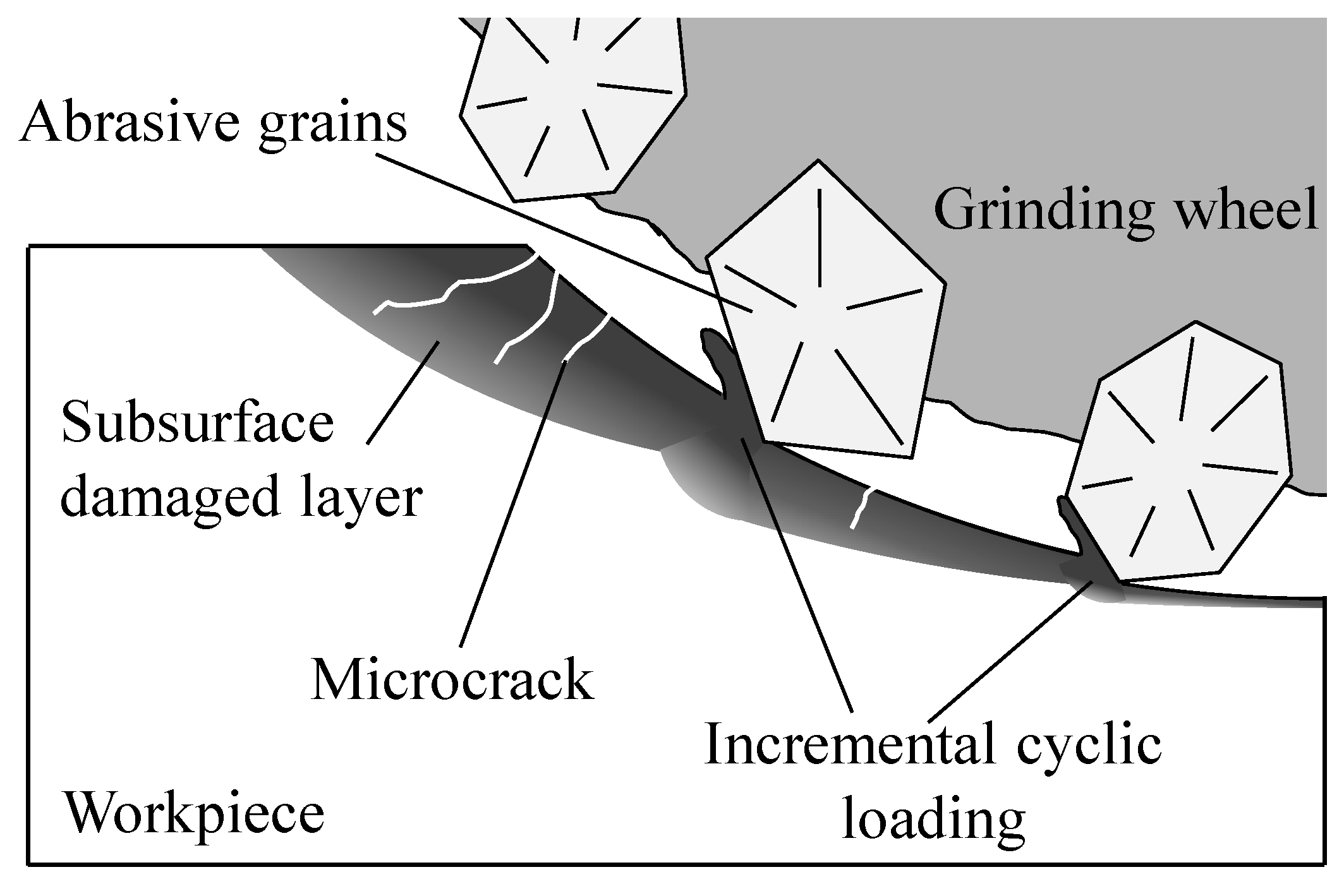
:1. Introduction
2. Experimental Details
3. Results and Discussion
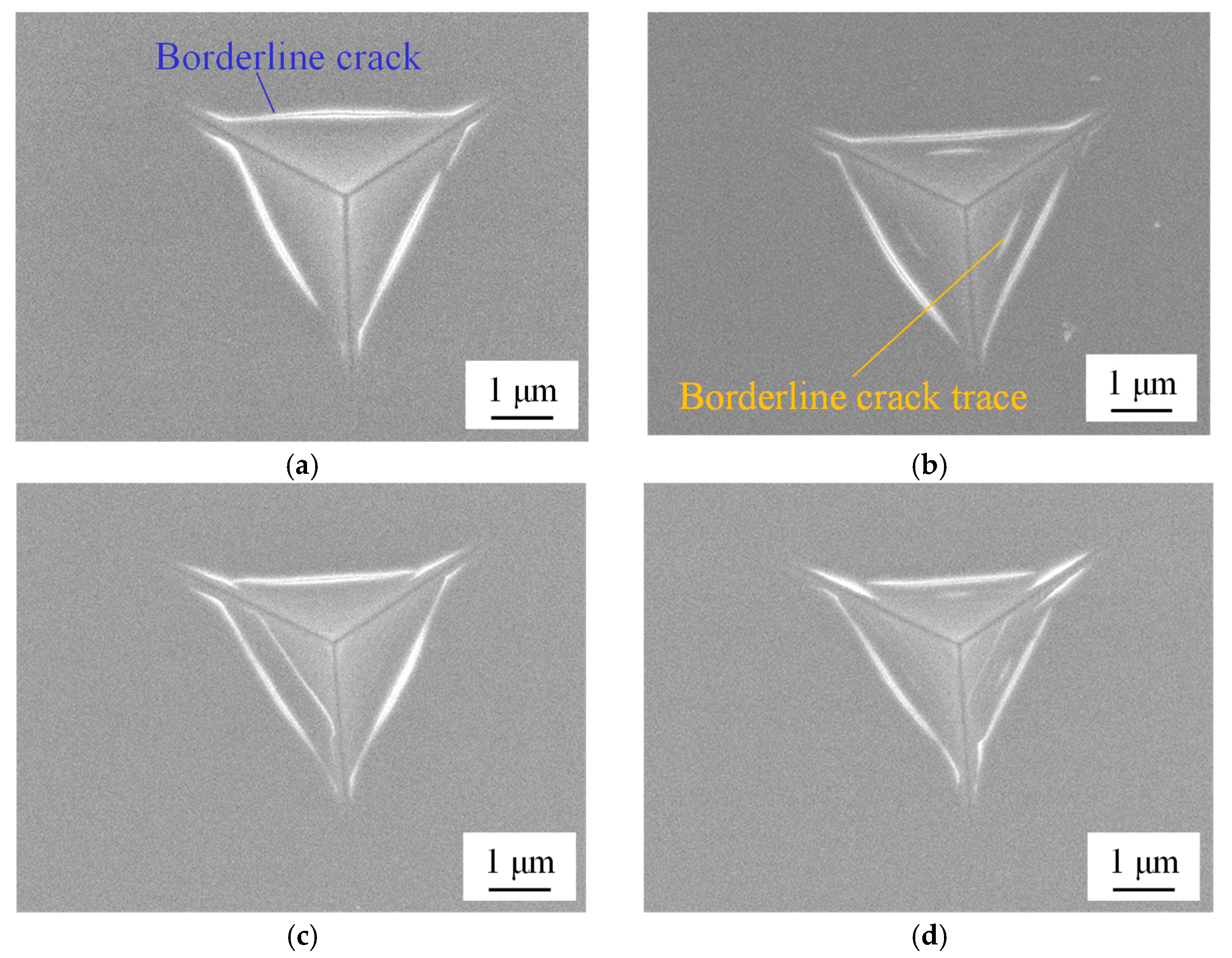
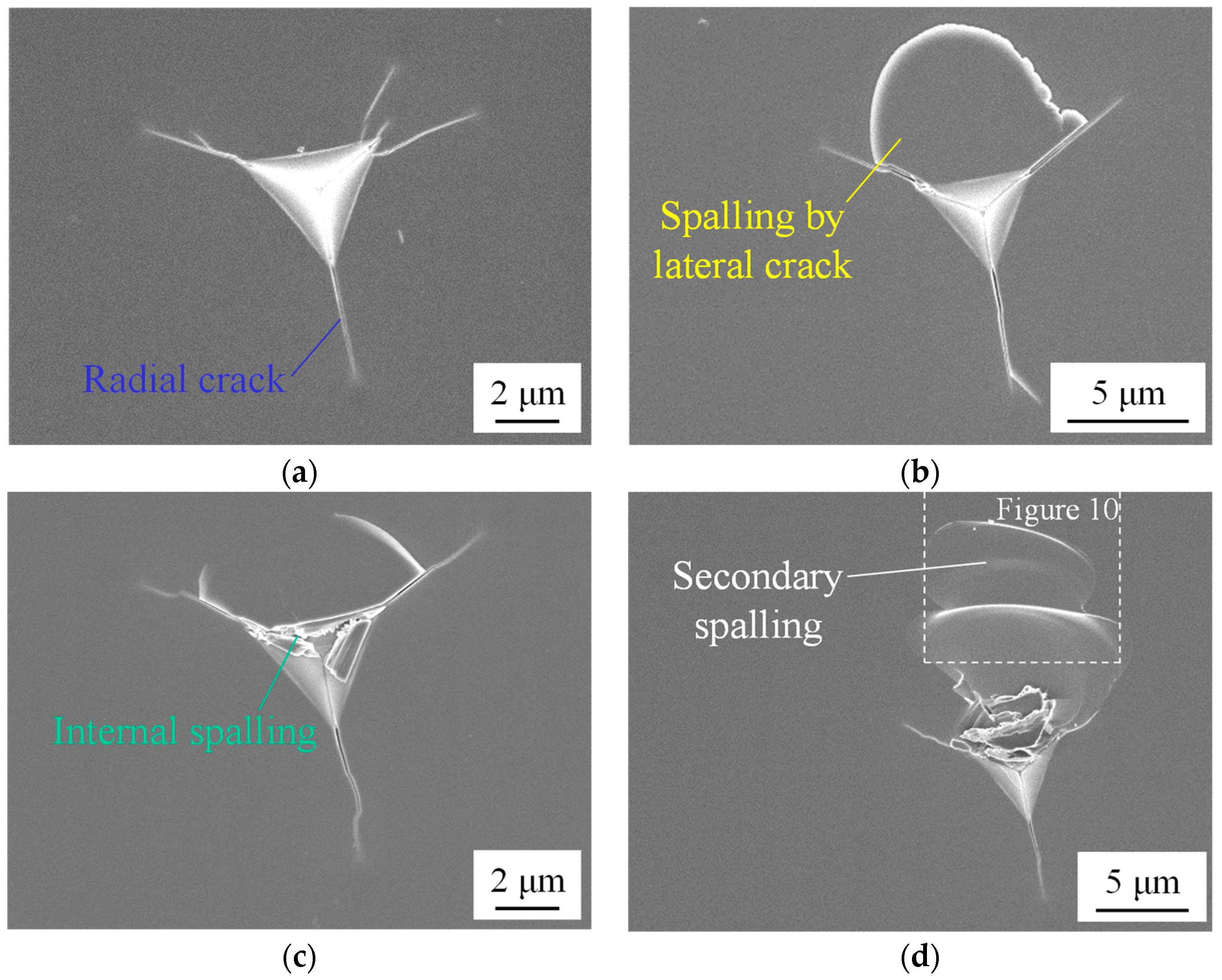
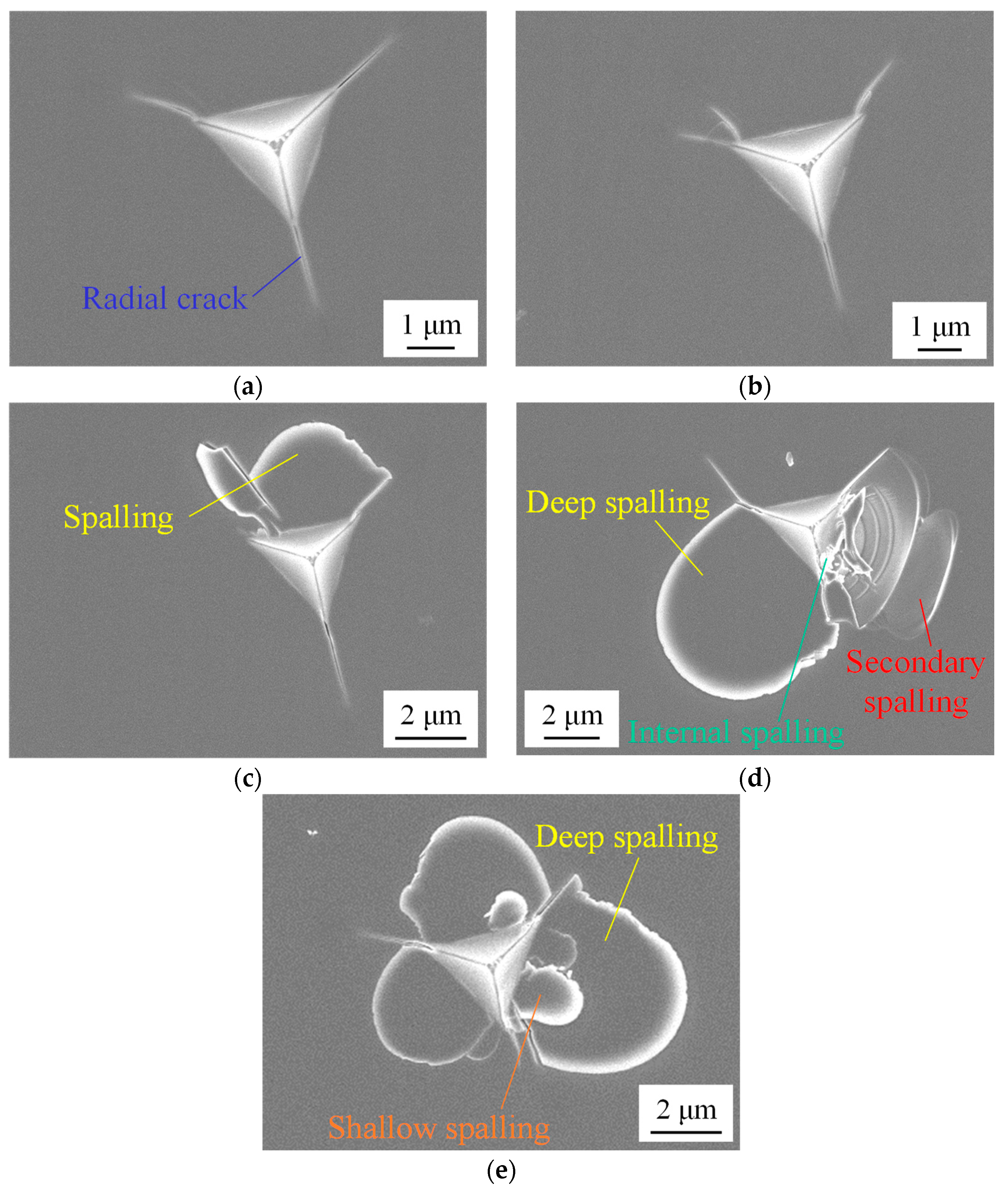
3.1. Observation of Indent Surface
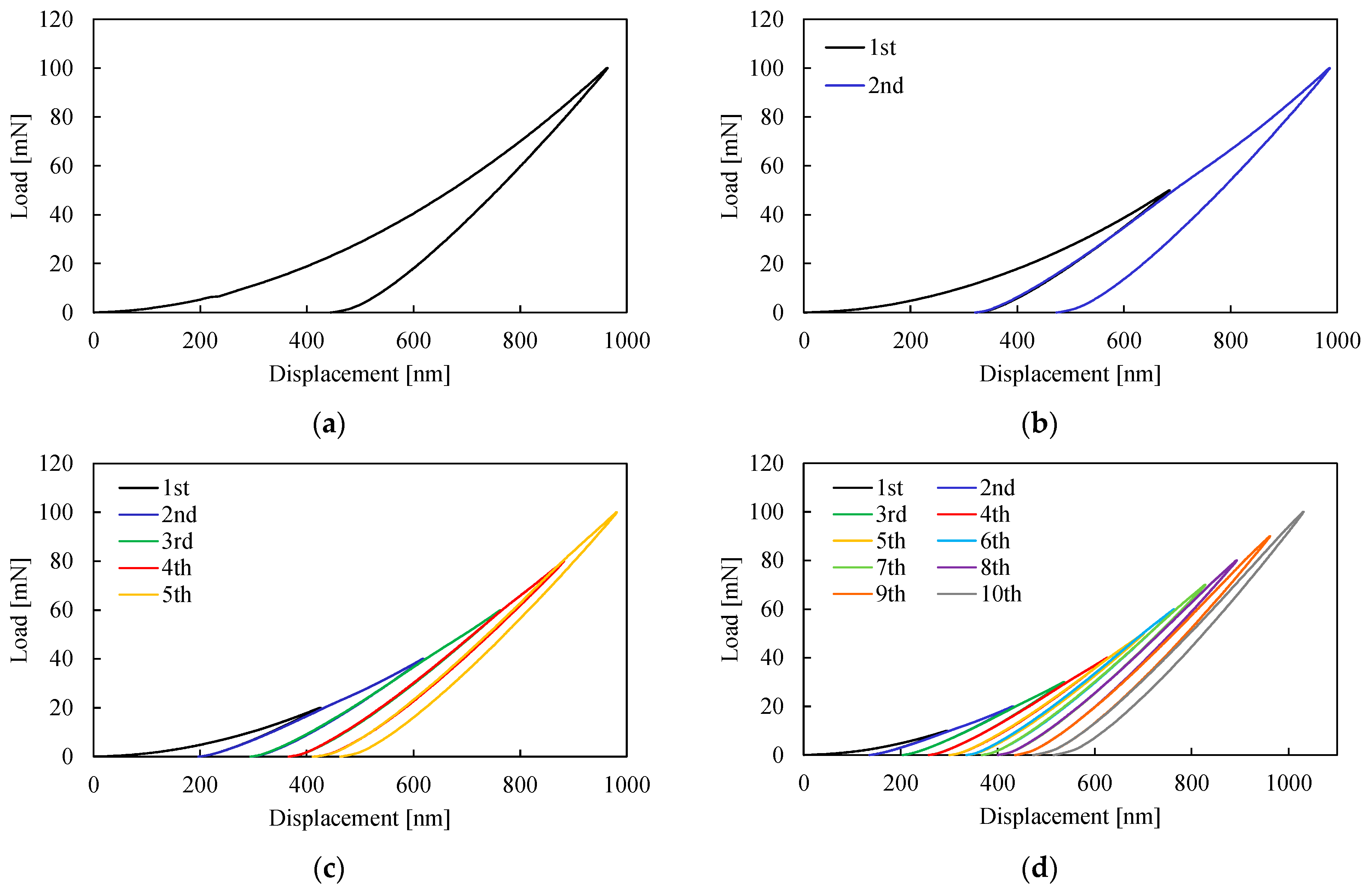
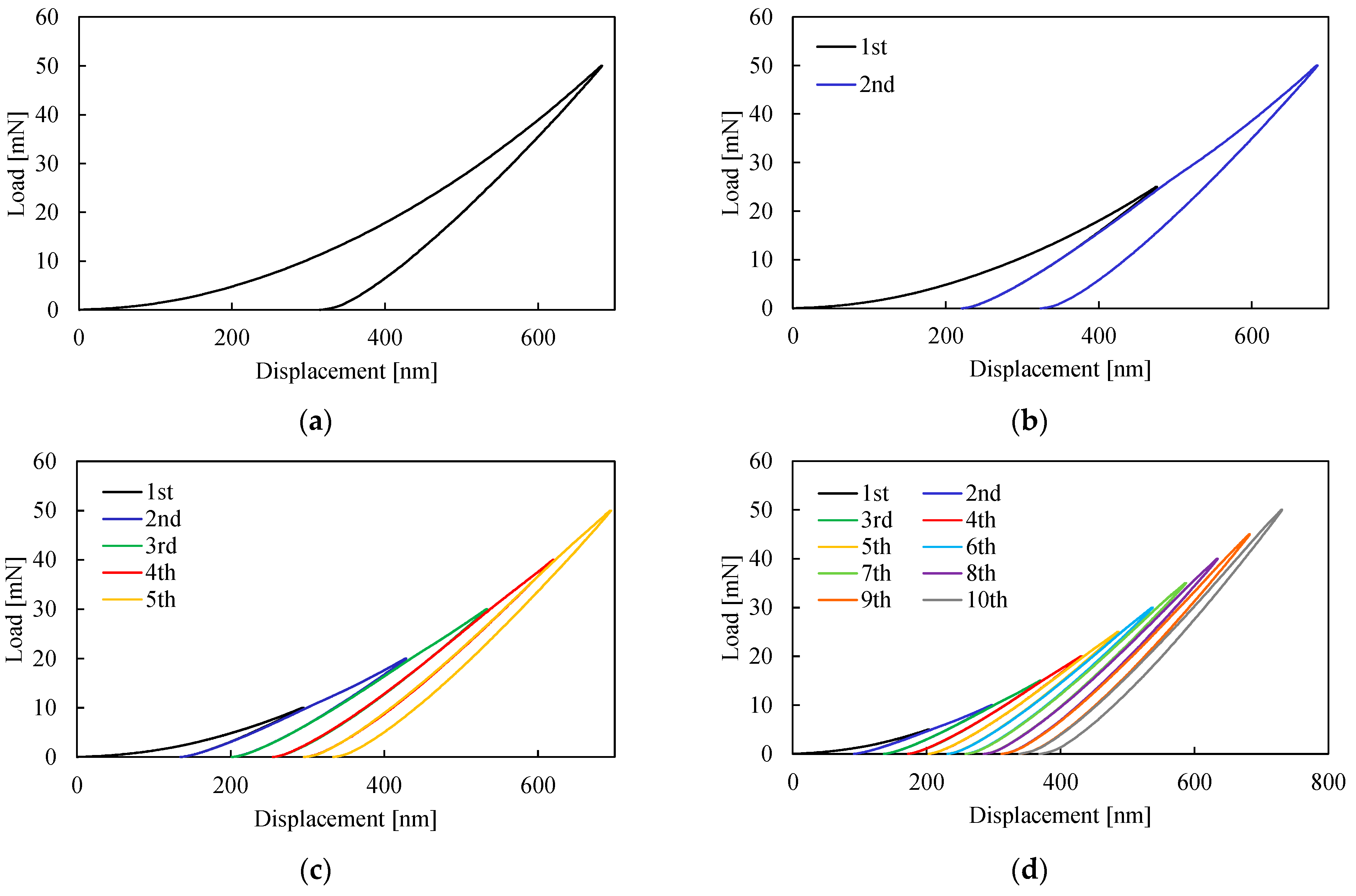
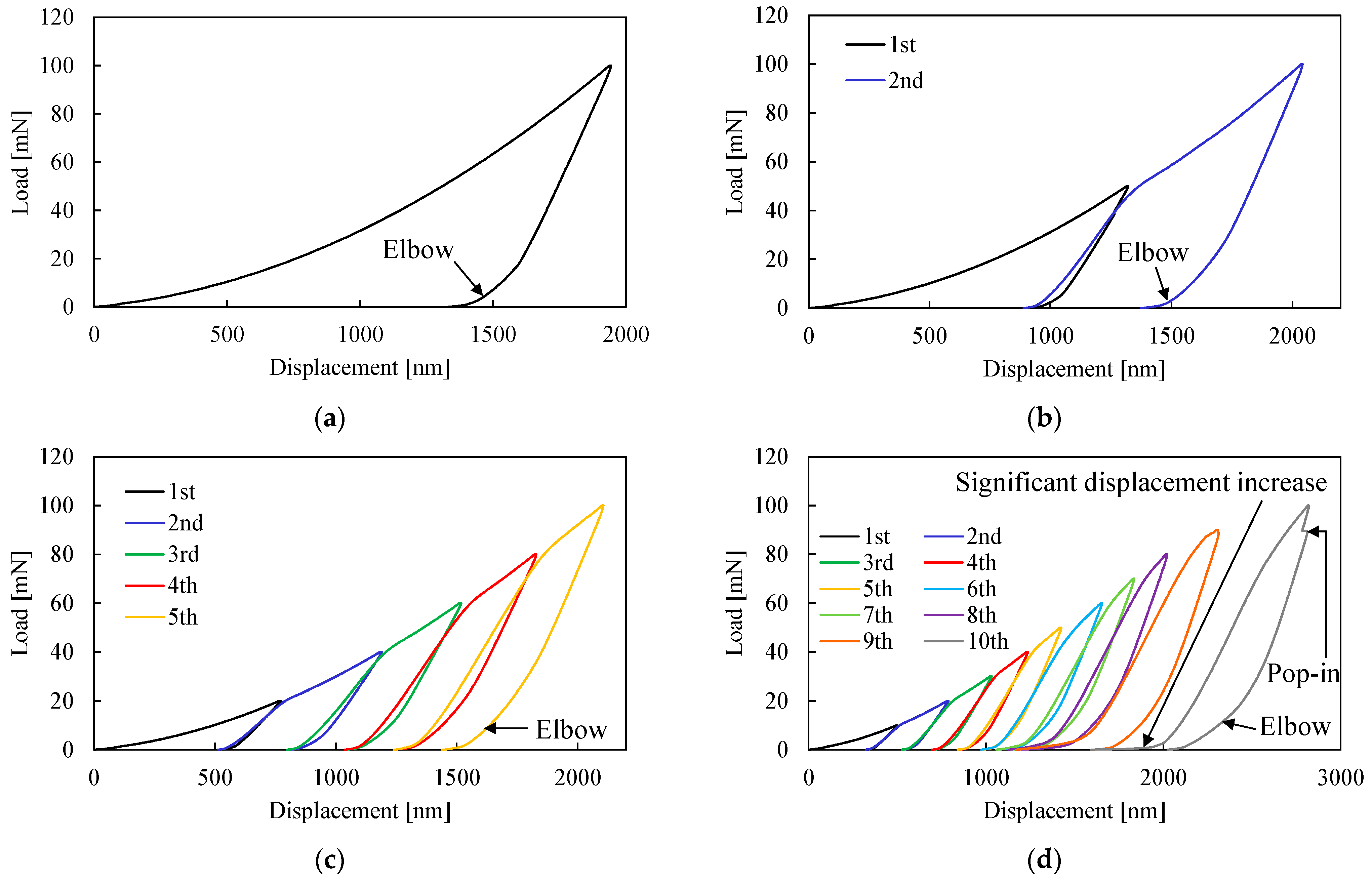
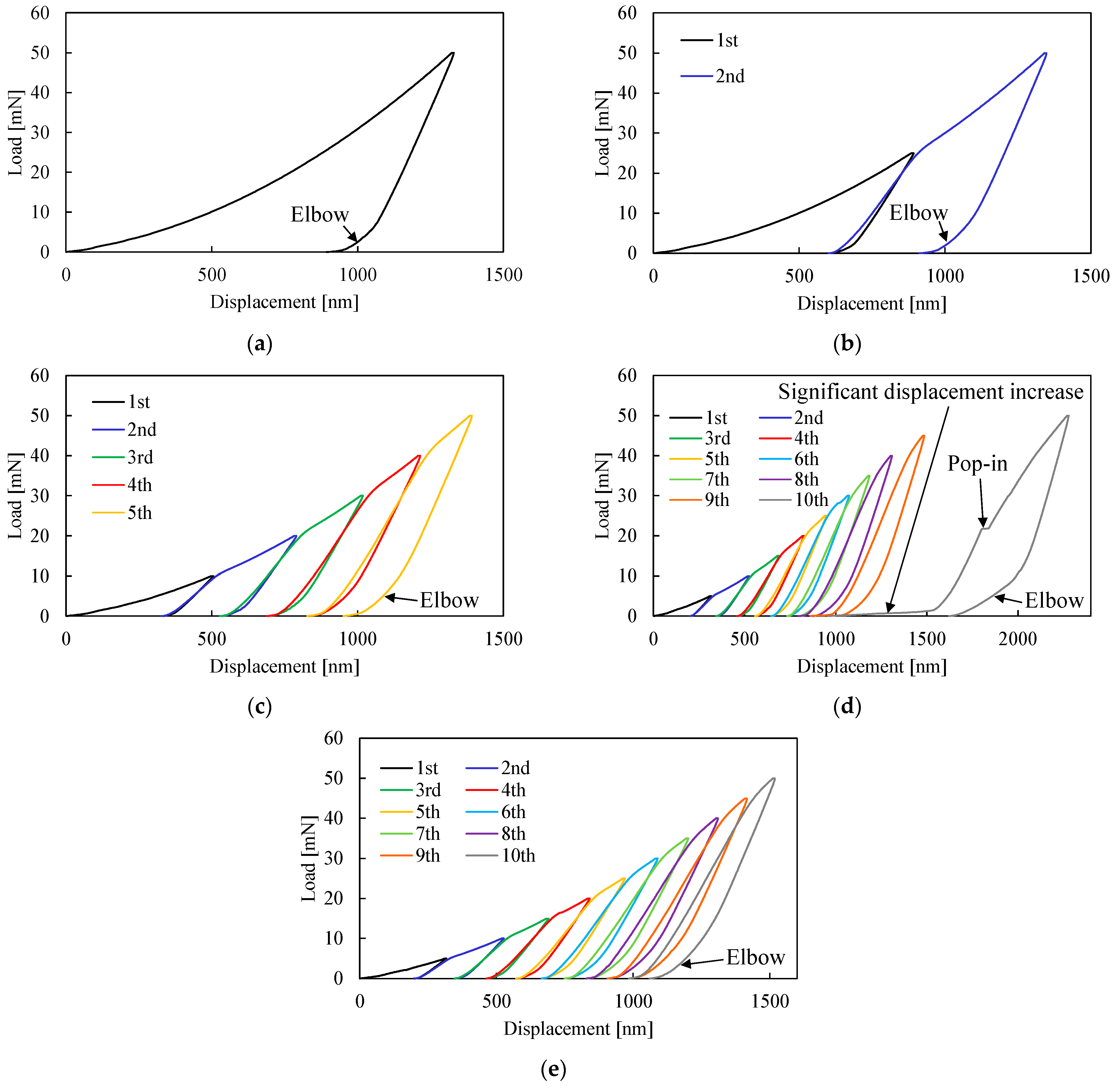
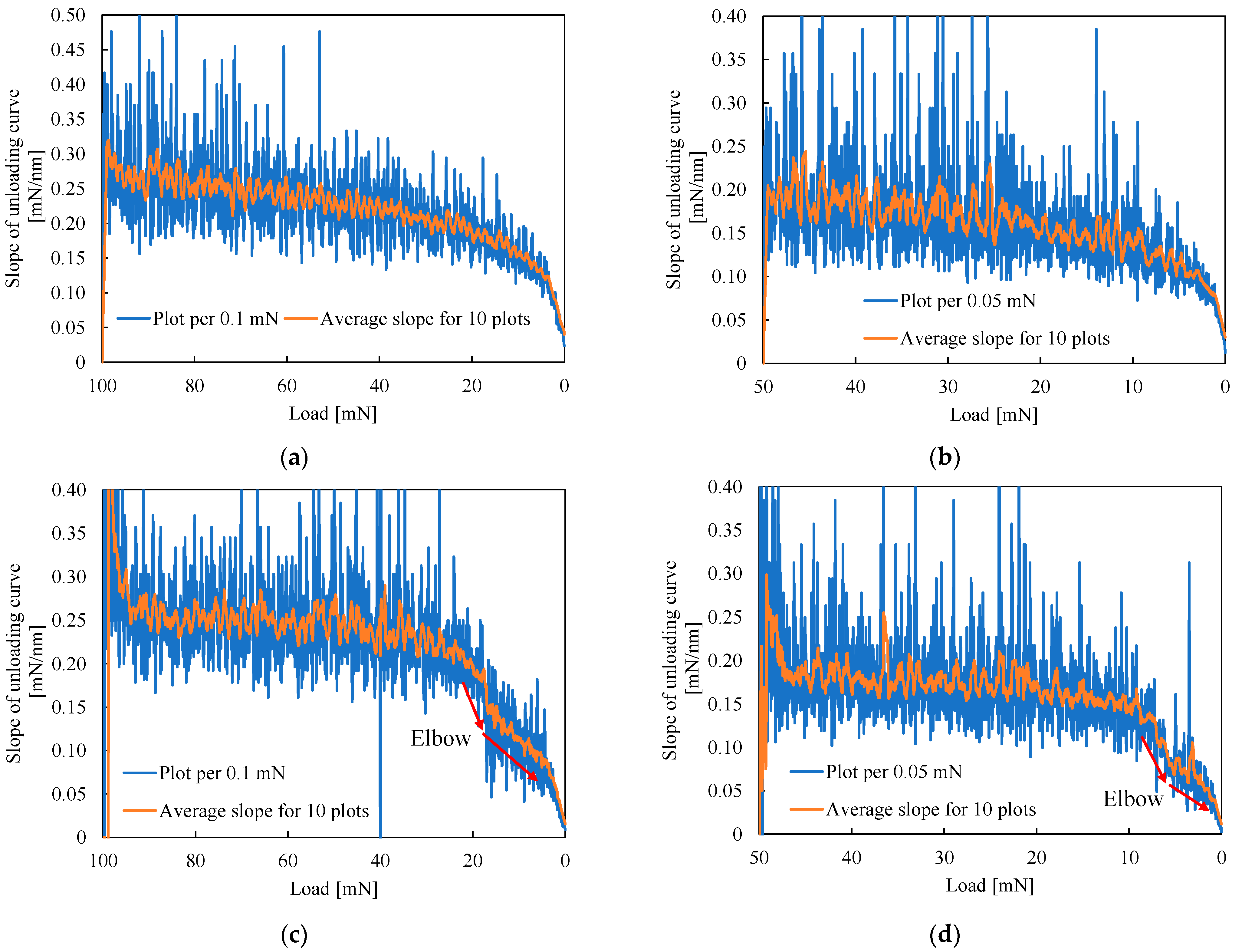
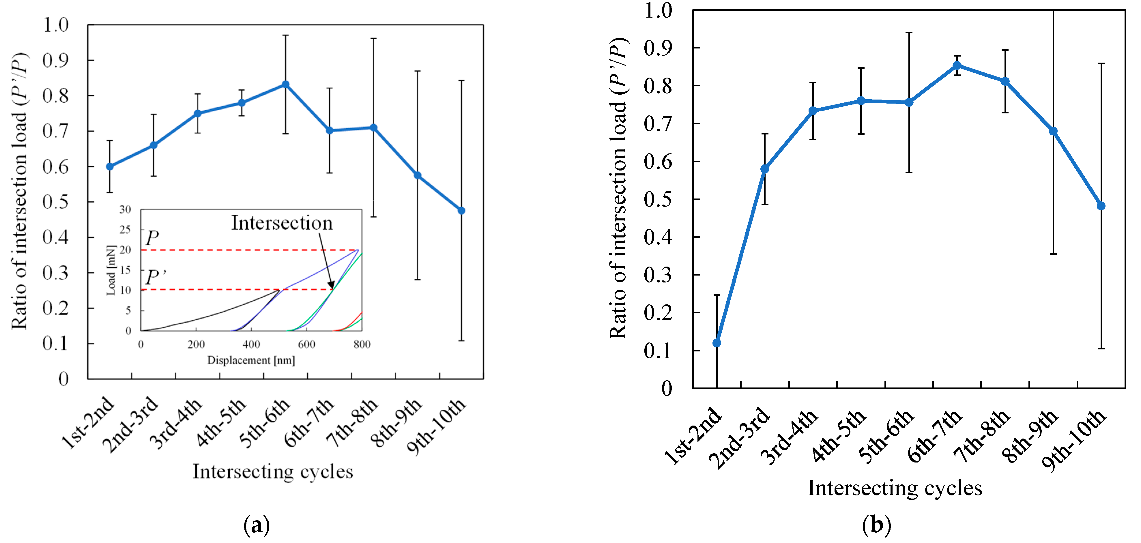
3.2. Load–Displacement Curve Analysis
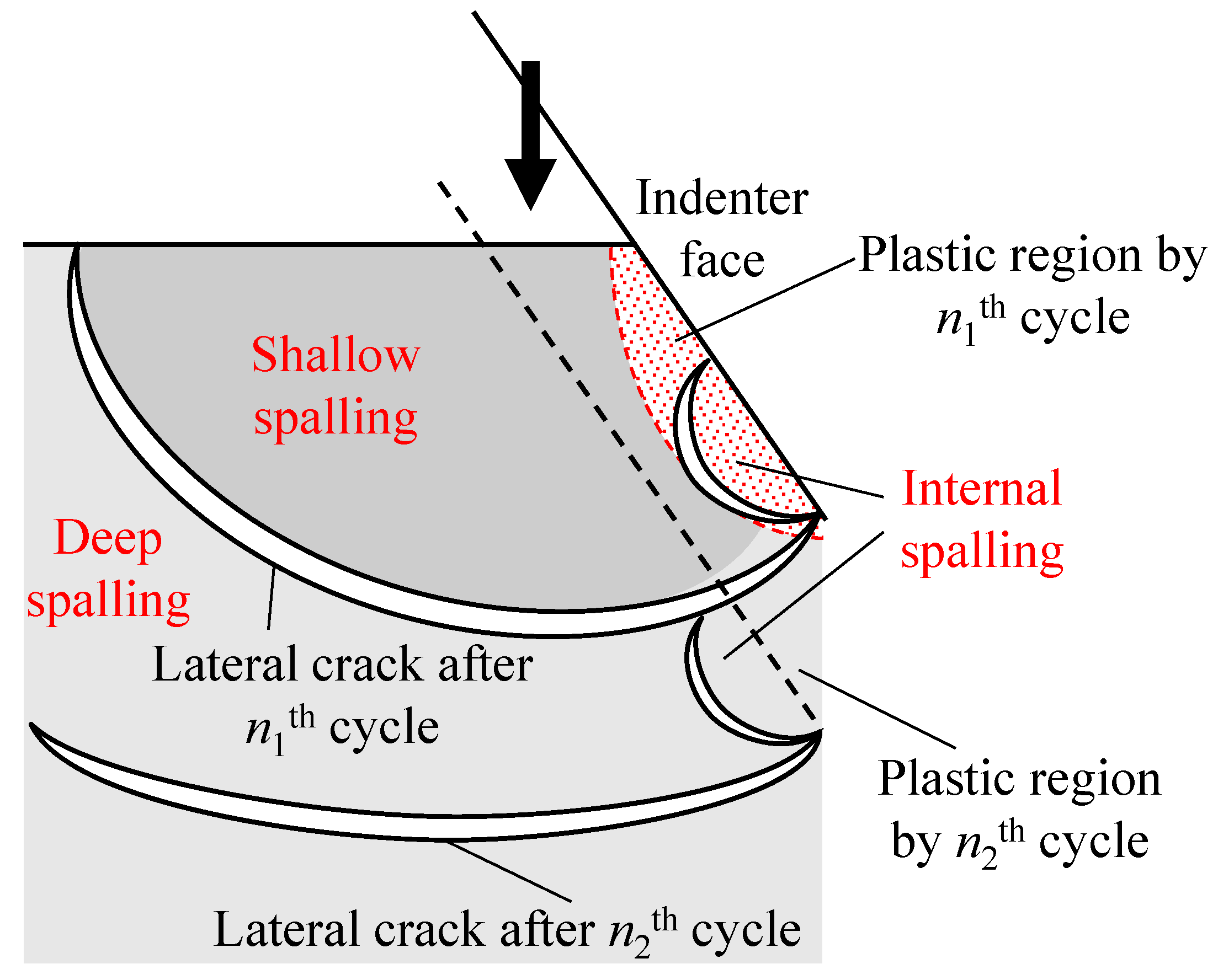
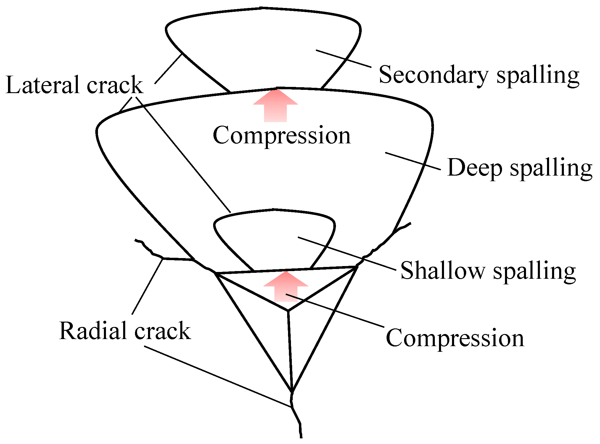
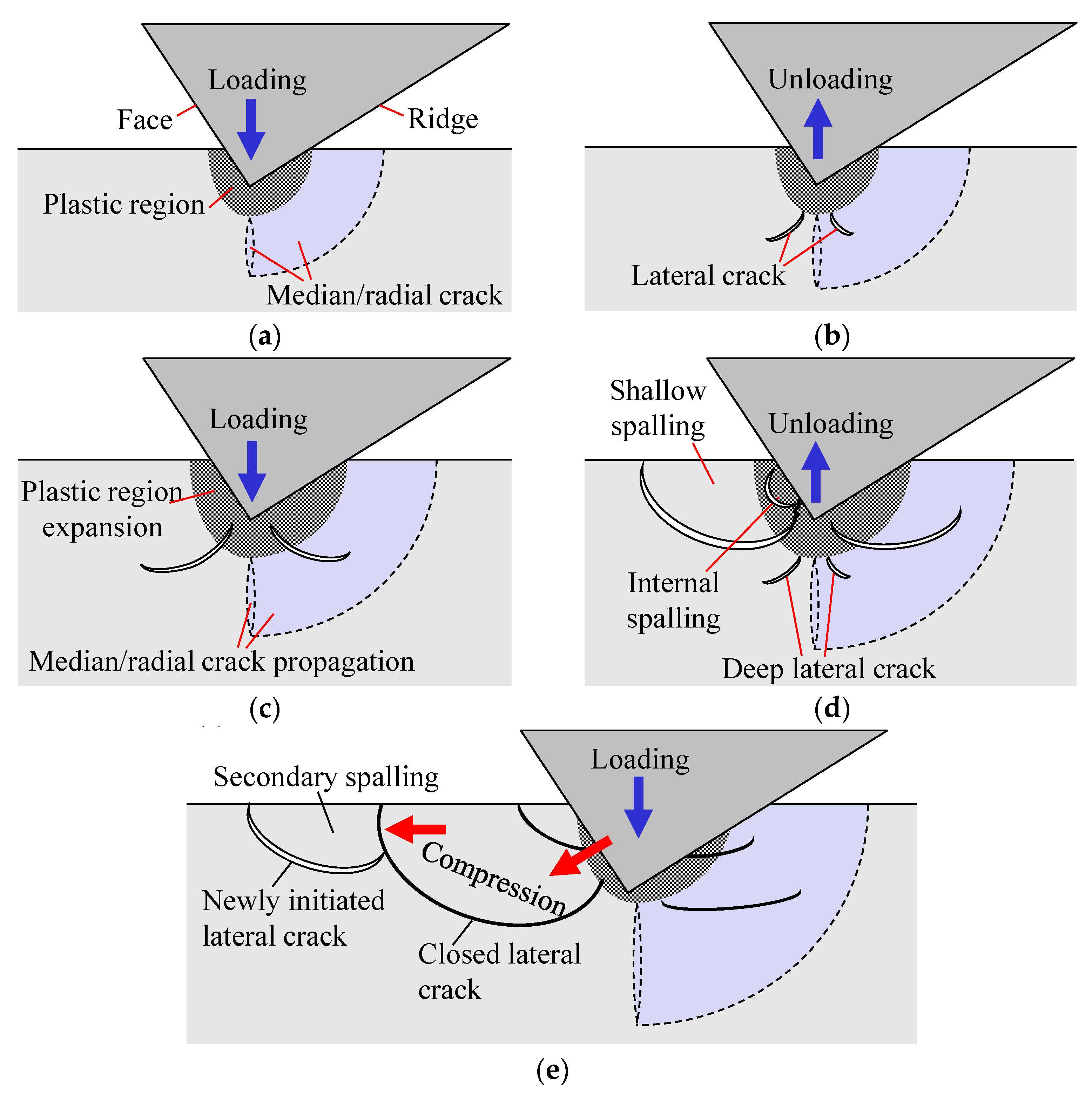
3.3. Crack Generation/Propagation Mechanisms
4. Conclusions
- (1)
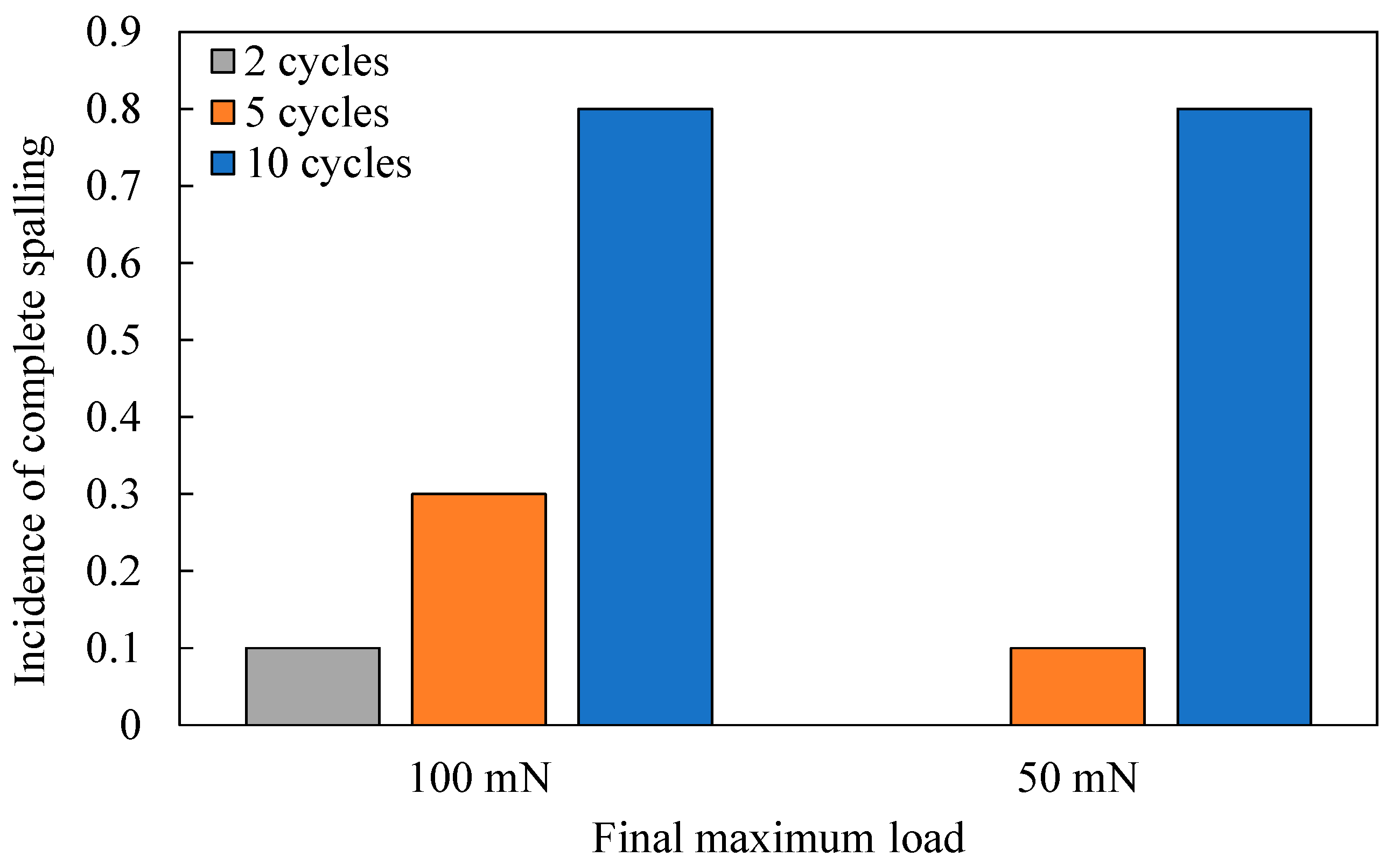
- Surface spalling becomes significant as indentation cycle increases when a cube-corner indenter is used, while a Berkovich indenter induces no surface spalling under the present experimental conditions.
- (2)
- Four types of characteristic patterns of surface spalling were identified: shallow spalling, deep spalling, internal spalling, and secondary spalling. The latter three kinds of spalling patterns only occur in incremental-load cyclic indentations.
- (3)
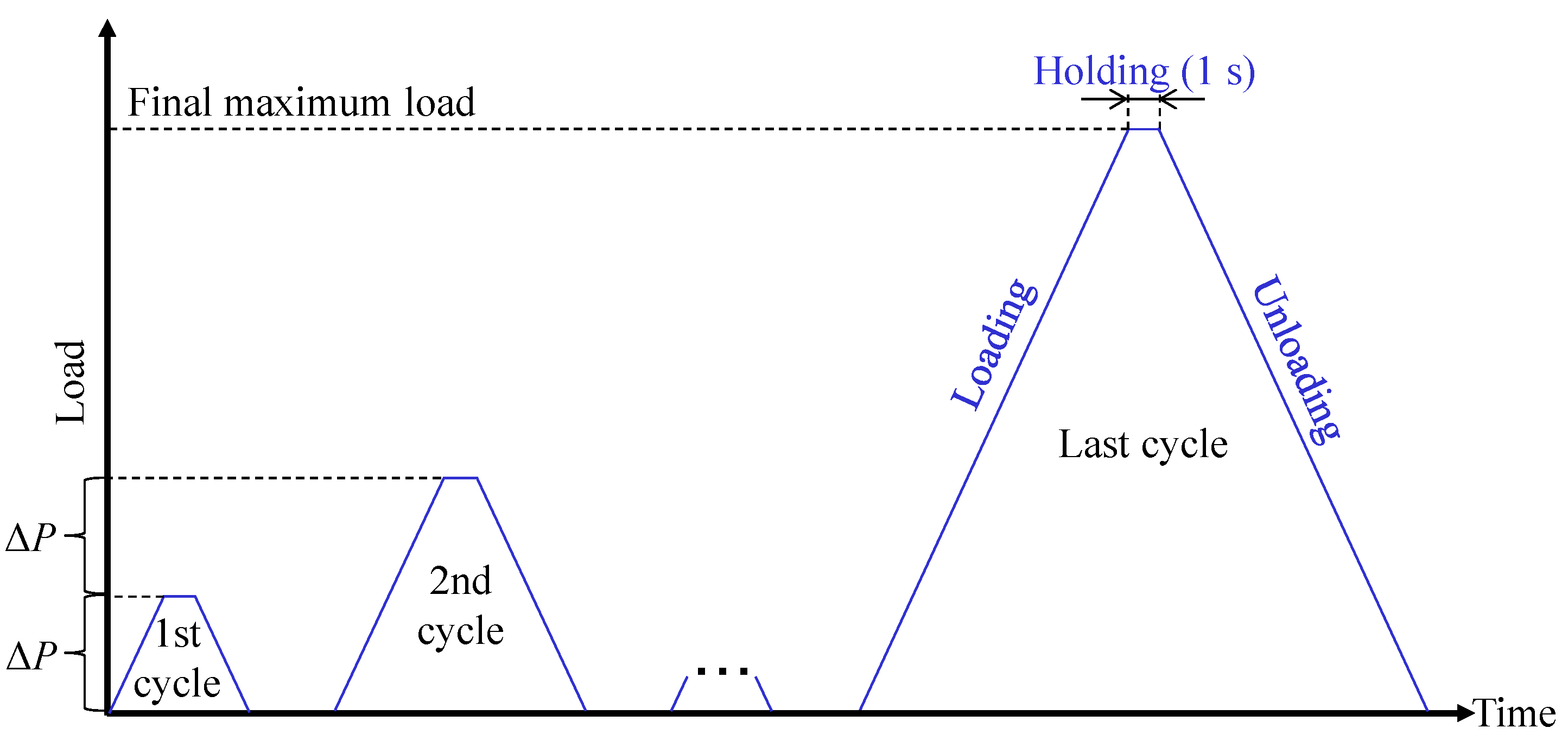
- The load–displacement curves exhibit unique features such as repetitive elbows, large pop-ins and significant displacement increase at the initial part of loading, which correspond to the incremental propagation of lateral cracks and surface spalling.
- (4)
- Multi-cyclic indentation using a cube-corner indenter promotes subsurface crack propagation and surface spalling (material removal) both in depth direction and in lateral direction compared to single-cycle indentation.
Author Contributions
Funding
Institutional Review Board Statement
Informed Consent Statement
Data Availability Statement
Conflicts of Interest
References
- Fang, F.Z.; Zhang, X.D.; Weckenmann, A.; Zhang, G.X.; Evans, C. Manufacturing and measurement of freeform optics. CIRP Ann. Manuf. Technol. 2013, 62, 823–846. [Google Scholar] [CrossRef]
- Kakinuma, Y.; Konuma, Y.; Fukuta, M.; Tanaka, K. Ultra-precision grinding of optical glass lenses with La-doped CeO2 slurry. CIRP Ann. 2019, 68, 345–348. [Google Scholar] [CrossRef]
- Li, S.; Wang, Z.; Wu, Y. Relationship between subsurface damage and surface roughness of optical materials in grinding and lapping processes. J. Mater. Process. Technol. 2008, 205, 34–41. [Google Scholar] [CrossRef]
- Suratwala, T.; Steele, R.; Feit, M.D.; Wong, L.; Miller, P.; Menapace, J.; Davis, P. Effect of rogue particles on the sub-surface damage of fused silica during grinding/polishing. J. Non-Cryst. Solids 2008, 354, 2023–2037. [Google Scholar] [CrossRef] [Green Version]
- Wang, J.; Li, Y.; Han, J.; Xu, Q.; Guo, Y. Evaluating subsurface damage in optical glasses. J. Eur. Opt. Soc. 2011, 6, 11011. [Google Scholar] [CrossRef]
- Cook, R.F.; Pharr, G.M. Direct Observation and Analysis of Indentation Cracking in Glasses and Ceramics. J. Am. Ceram. Soc. 1990, 73, 787–817. [Google Scholar] [CrossRef]
- Elfallagh, F.; Inkson, B.J. 3D analysis of crack morphologies in silicate glass using FIB tomography. J. Eur. Ceram. Soc. 2009, 29, 47–52. [Google Scholar] [CrossRef]
- Whittle, B.R.; Hand, R.J. Morphology of Vickers Indent Flaws in Soda-Lime-Silica Glass. J. Am. Ceram. Soc. 2001, 84, 2361–2365. [Google Scholar] [CrossRef]
- Li, C.; Zhang, L.; Sun, L.; Yang, S.; Wu, C.; Long, X.; Ding, J.; Jiang, Z. A quantitative analysis of the indentation fracture of fused silica. J. Am. Ceram. Soc. 2019, 102, 7264–7277. [Google Scholar] [CrossRef]
- Januchta, K.; Liu, P.; Hansen, S.R.; To, T.; Smedskjaer, M.M. Indentation cracking and deformation mechanism of sodium aluminoborosilicate glasses. J. Am. Ceram. Soc. 2020, 103, 1656–1665. [Google Scholar] [CrossRef]
- Morris, D.J.; Cook, R.F. In situ cube-corner indentation of soda-lime glass and fused silica. J. Am. Ceram. Soc. 2004, 87, 1494–1501. [Google Scholar] [CrossRef]
- Suratwala, T.; Wong, L.; Miller, P.; Feit, M.D.; Menapace, J.; Steele, R.; Davis, P.; Walmer, D. Sub-surface mechanical damage distributions during grinding of fused silica. J. Non-Cryst. Solids 2006, 352, 5601–5617. [Google Scholar] [CrossRef] [Green Version]
- Wang, W.; Yao, P.; Wang, J.; Huang, C.; Zhu, H.; Zou, B.; Liu, H.; Yan, J. Crack-free ductile mode grinding of fused silica under controllable dry grinding conditions. Int. J. Mach. Tools Manuf. 2016, 109, 126–136. [Google Scholar] [CrossRef]
- Li, P.; Chen, S.; Xiao, H.; Chen, Z.; Qu, M.; Dai, H.; Jin, T. Effects of local strain rate and temperature on the workpiece subsurface damage in grinding of optical glass. Int. J. Mech. Sci. 2020, 182, 105737. [Google Scholar] [CrossRef]
- Chen, J.; Fang, Q.; Li, P. Effect of grinding wheel spindle vibration on surface roughness and subsurface damage in brittle material grinding. Int. J. Mach. Tools Manuf. 2015, 91, 12–23. [Google Scholar] [CrossRef]
- Huang, H.; Yan, J. On the mechanism of secondary pop-out in cyclic nanoindentation of single-crystal silicon. J. Mater. Res. 2015, 30, 1861–1868. [Google Scholar] [CrossRef]
- Huang, H.; Yan, J. New insights into phase transformations in single crystal silicon by controlled cyclic nanoindentation. Scr. Mater. 2015, 102, 35–38. [Google Scholar] [CrossRef]
- Kosai, K.; Huang, H.; Yan, J. Comparative Study of Phase Transformation in Single-Crystal Germanium during Single and Cyclic Nanoindentation. Crystals 2017, 7, 333. [Google Scholar] [CrossRef] [Green Version]
- Kosai, K.; Yan, J. Direct observations of multi-cyclic nanoindentation-induced phase transformations in single-crystal Ge. Mater. Res. Express 2019, 6, 75065. [Google Scholar] [CrossRef]
- Banerjee, R.; Sarkar, B.K. Crack initiation by indentation fatigue in lead alkali and soda-lime glass. J. Am. Ceram. Soc. 1997, 80, 2722–2724. [Google Scholar] [CrossRef]
- Kim, D.K.; Jung, Y.G.; Peterson, I.M.; Lawn, B.R. Cyclic fatigue of intrinsically brittle ceramics in contact with spheres. Acta Mater. 1999, 47, 4711–4725. [Google Scholar] [CrossRef]
- Sglavo, V.M.; Gadotti, M.; Micheletti, T. Cyclic loading behaviour of soda-lime silicate glass using indentation cracks. Fatigue Fract. Eng. Mater. Struct. 1997, 20, 1225–1234. [Google Scholar] [CrossRef]
- Morris, D.J.; Cook, R.F. Radial fracture during indentation by acute probes: I, description by an indentation wedging model. Int. J. Fract. 2005, 136, 237–264. [Google Scholar] [CrossRef]
- Morris, D.J.; Vodnick, A.M.; Cook, R.F. Radial fracture during indentation by acute probes: II, experimental observations of cube-corner and vickers indentation. Int. J. Fract. 2005, 136, 265–284. [Google Scholar] [CrossRef]
- Wang, W.; Li, Z.; Yao, P.; Li, J.; Chen, F.; Liu, Y. Sink-in/pile-up formation and crack nucleation mechanisms of high purity fused silica and soda-lime silica glass during nanoindentation experiments. Ceram. Int. 2020, 46, 24698–24709. [Google Scholar] [CrossRef]
- Domnich, V.; Gogotsi, Y.; Dub, S. Effect of phase transformations on the shape of the unloading curve in the nanoindentation of silicon. Appl. Phys. Lett. 2000, 76, 2214–2216. [Google Scholar] [CrossRef]
- Oliver, D.J.; Bradby, J.E.; Williams, J.S.; Swain, M.V.; Munroe, P. Rate-dependent phase transformations in nanoindented germanium. J. Appl. Phys. 2009, 105, 126101. [Google Scholar] [CrossRef] [Green Version]
- Rabe, R.; Breguet, J.M.; Schwaller, P.; Stauss, S.; Haug, F.J.; Patscheider, J.; Michler, J. Observation of fracture and plastic deformation during indentation and scratching inside the scanning electron microscope. Thin Solid Film. 2004, 469–470, 206–213. [Google Scholar] [CrossRef]
- Hainsworth, S.V.; McGurk, M.R.; Page, T.F. The effect of coating cracking on the indentation response of thin hard-coated systems. Surf. Coat. Technol. 1998, 102, 97–107. [Google Scholar] [CrossRef]
- Lawn, B.; Wilshaw, R. Indentation fracture: Principles and applications. J. Mater. Sci. 1975, 10, 1049–1081. [Google Scholar] [CrossRef]
- Marshall, D.B.; Lawn, B.R.; Evans, A.G. Elastic/Plastic Indentation Damage in Ceramics: The Lateral Crack System. J. Am. Ceram. Soc. 1982, 65, 561–566. [Google Scholar] [CrossRef]
- Keryvin, V.; Charleux, L.; Hin, R.; Guin, J.P.; Sangleboeuf, J.C. Mechanical behaviour of fully densified silica glass under Vickers indentation. Acta Mater. 2017, 129, 492–499. [Google Scholar] [CrossRef] [Green Version]
- Ohta, T.; Yan, J.; Kuriyagawa, T.; Kodera, S.; Nakasuji, T. Prediction of subsurface damage depth of ground brittle materials by surface profiling. Int. J. Mach. Mach. Mater. 2007, 2, 108–124. [Google Scholar] [CrossRef]
- Xiao, H.; Chen, Z.; Wang, H.; Wang, J.; Zhu, N. Effect of grinding parameters on surface roughness and subsurface damage and their evaluation in fused silica. Opt. Express 2018, 26, 4638–4655. [Google Scholar] [CrossRef]
- Sun, R.; Huang, Y.; Zhang, X.; Zhao, F.; Zhang, Y.; Liu, J.; Hu, J. Study on subsurface damage of fused quartz in grinding stage. In Proceedings of the Eighth Symposium on Novel Photoelectronic Detection Technology and Applications, Kunming, China, 27 March 2022; Proc. SPIE Volume 12169. [Google Scholar] [CrossRef]


| Material Properties | Values |
|---|---|
| Vickers hardness [GPa] | 8.9 |
| Young’s modulus [GPa] | 74 |
| Poisson’s ratio | 0.17 |
| Bending strength [MPa] | 94.3 |
| Compressive strength [MPa] | 1130 |
| Size [mm] | Φ10 × 3 |
| OH content [ppm] | <200 |
| Impurity | Ppb level |
| Indentation Parameters | Values |
|---|---|
| Final maximum load [mN] | 50, 100 |
| Loading/unloading rate [mN/s] | 1 |
| The number of indentation cycle | 2, 5, 10 |
| The number of tests at each condition | 10 |
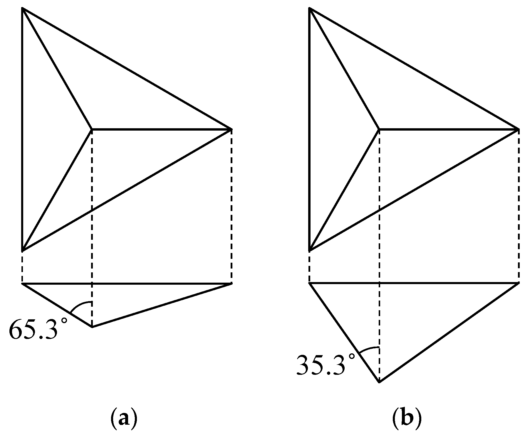
| Indenter geometry | Berkovich, cube-corner |
| Indenter material | Single-crystal diamond |
Publisher’s Note: MDPI stays neutral with regard to jurisdictional claims in published maps and institutional affiliations. |
© 2022 by the authors. Licensee MDPI, Basel, Switzerland. This article is an open access article distributed under the terms and conditions of the Creative Commons Attribution (CC BY) license (https://creativecommons.org/licenses/by/4.0/).
Share and Cite
Kosai, K.; Zhao, Y.; Yan, J. Crack Propagation Behavior of Fused Silica during Cyclic Indentation under Incremental Loads. Appl. Sci. 2022, 12, 6589. https://doi.org/10.3390/app12136589
Kosai K, Zhao Y, Yan J. Crack Propagation Behavior of Fused Silica during Cyclic Indentation under Incremental Loads. Applied Sciences. 2022; 12(13):6589. https://doi.org/10.3390/app12136589
Chicago/Turabian StyleKosai, Koji, Yugang Zhao, and Jiwang Yan. 2022. "Crack Propagation Behavior of Fused Silica during Cyclic Indentation under Incremental Loads" Applied Sciences 12, no. 13: 6589. https://doi.org/10.3390/app12136589
APA StyleKosai, K., Zhao, Y., & Yan, J. (2022). Crack Propagation Behavior of Fused Silica during Cyclic Indentation under Incremental Loads. Applied Sciences, 12(13), 6589. https://doi.org/10.3390/app12136589