
Peridynamics for Fracture Analysis of Reflective Cracks in Semi-Rigid Base Asphalt Pavement

Abstract
:1. Introduction
2. Peridynamics
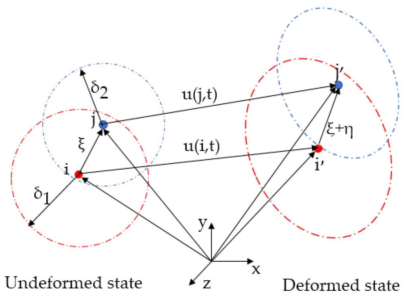
2.1. Peridynamics Theory
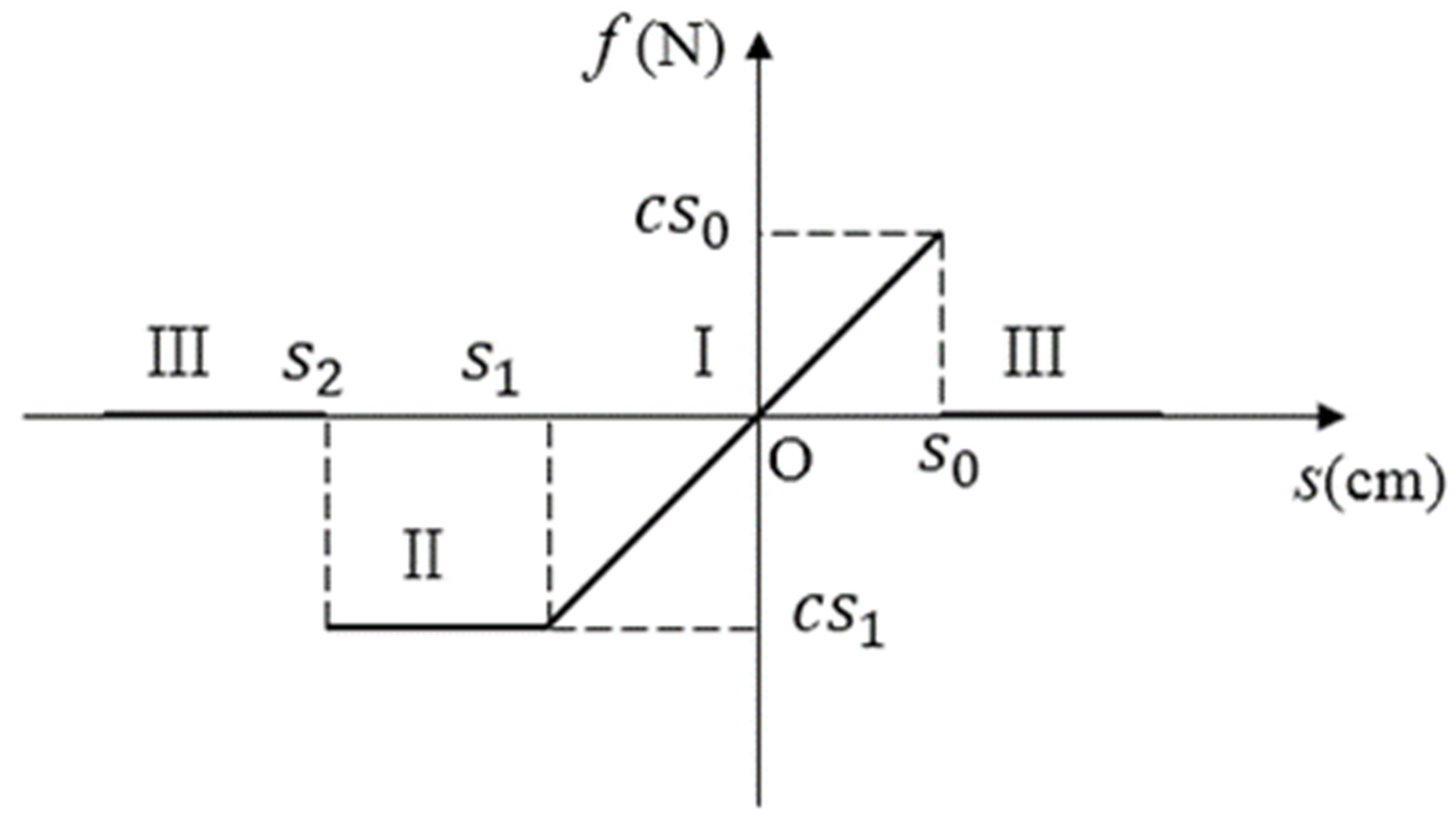
2.2. The Constitutive Relation
2.3. Numerical Implementation
2.4. PD Model of the Layered Structure
3. Numerical Model Validation
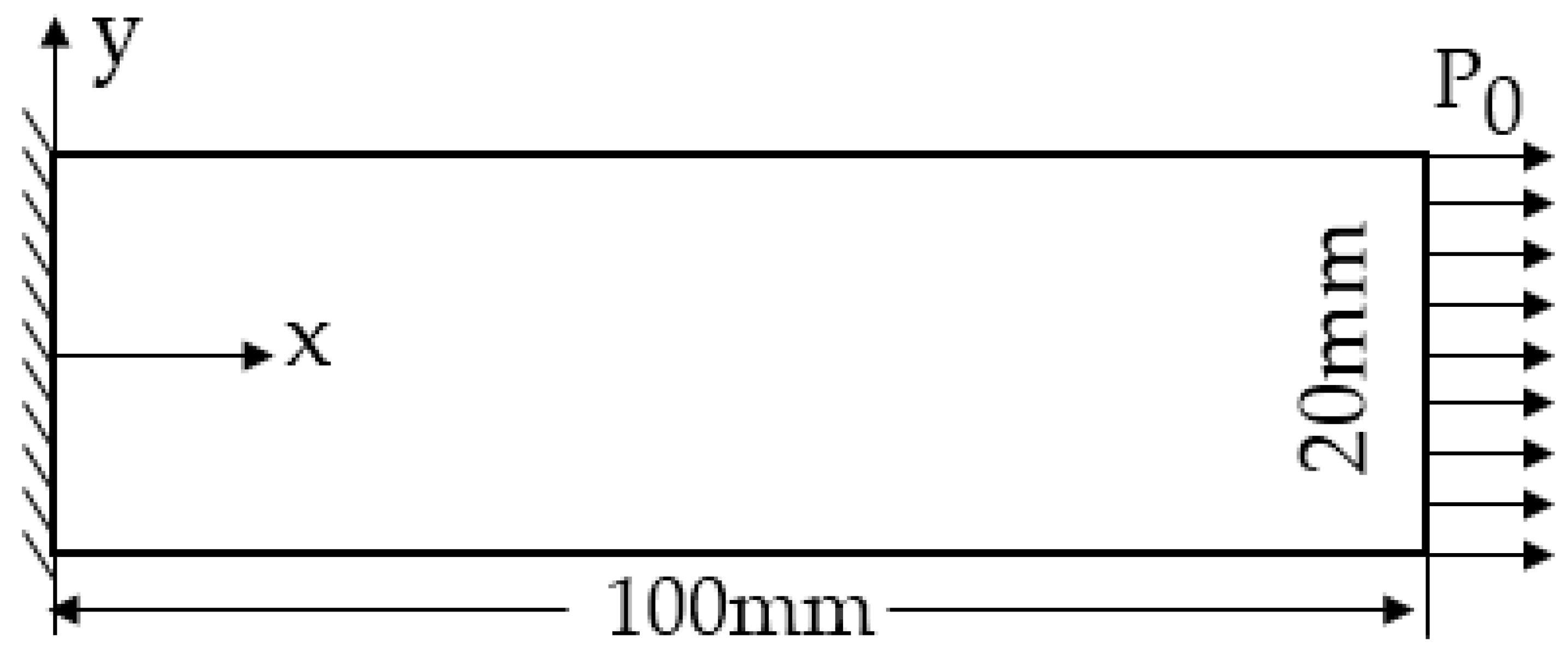
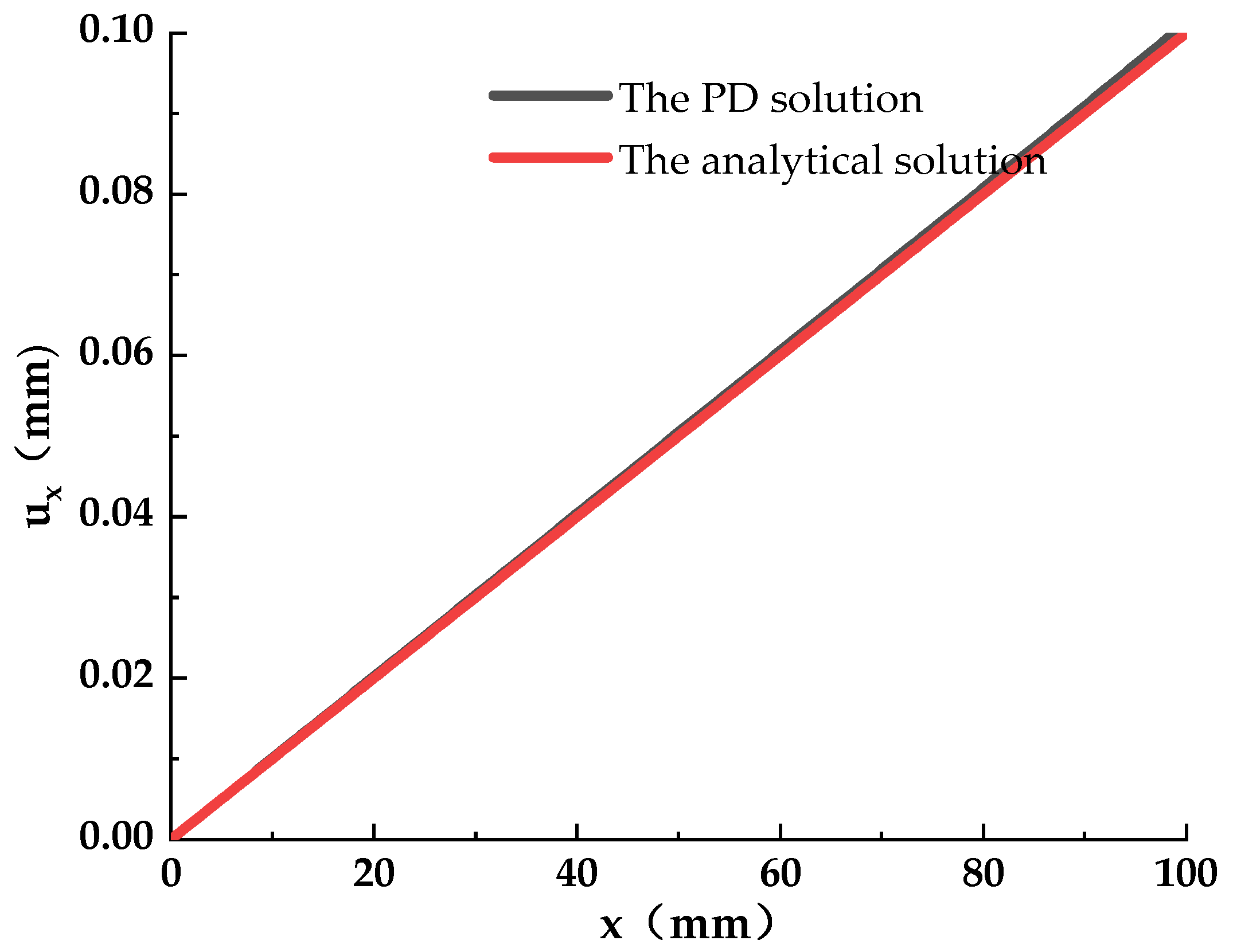
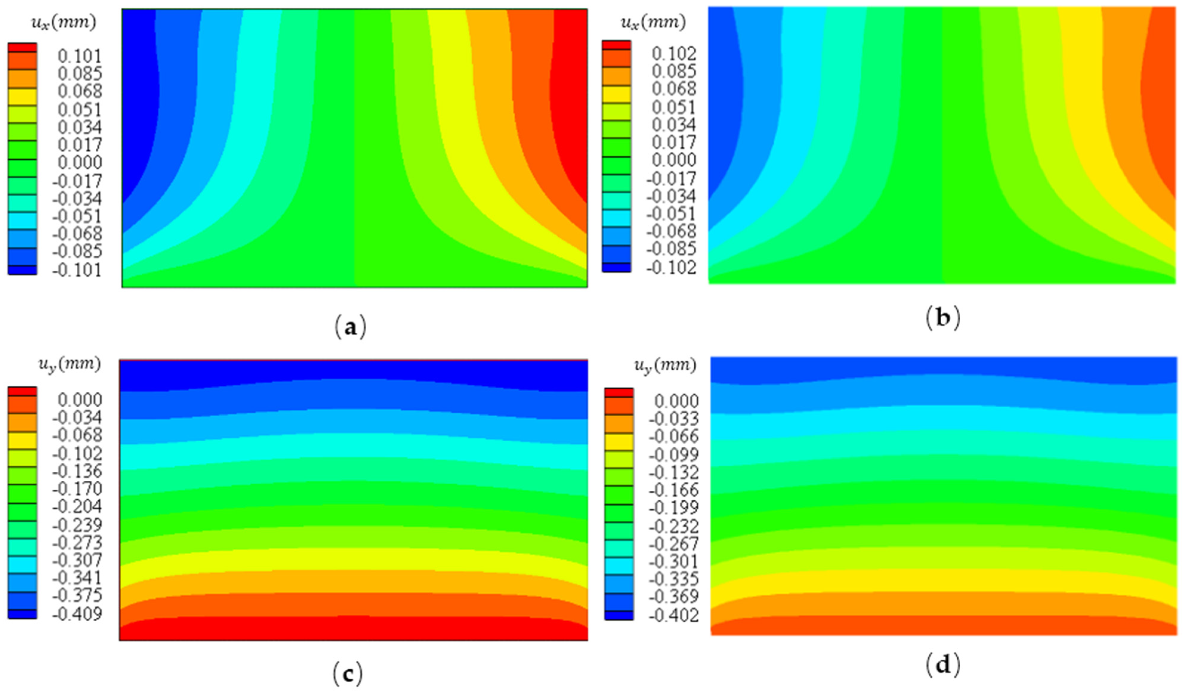
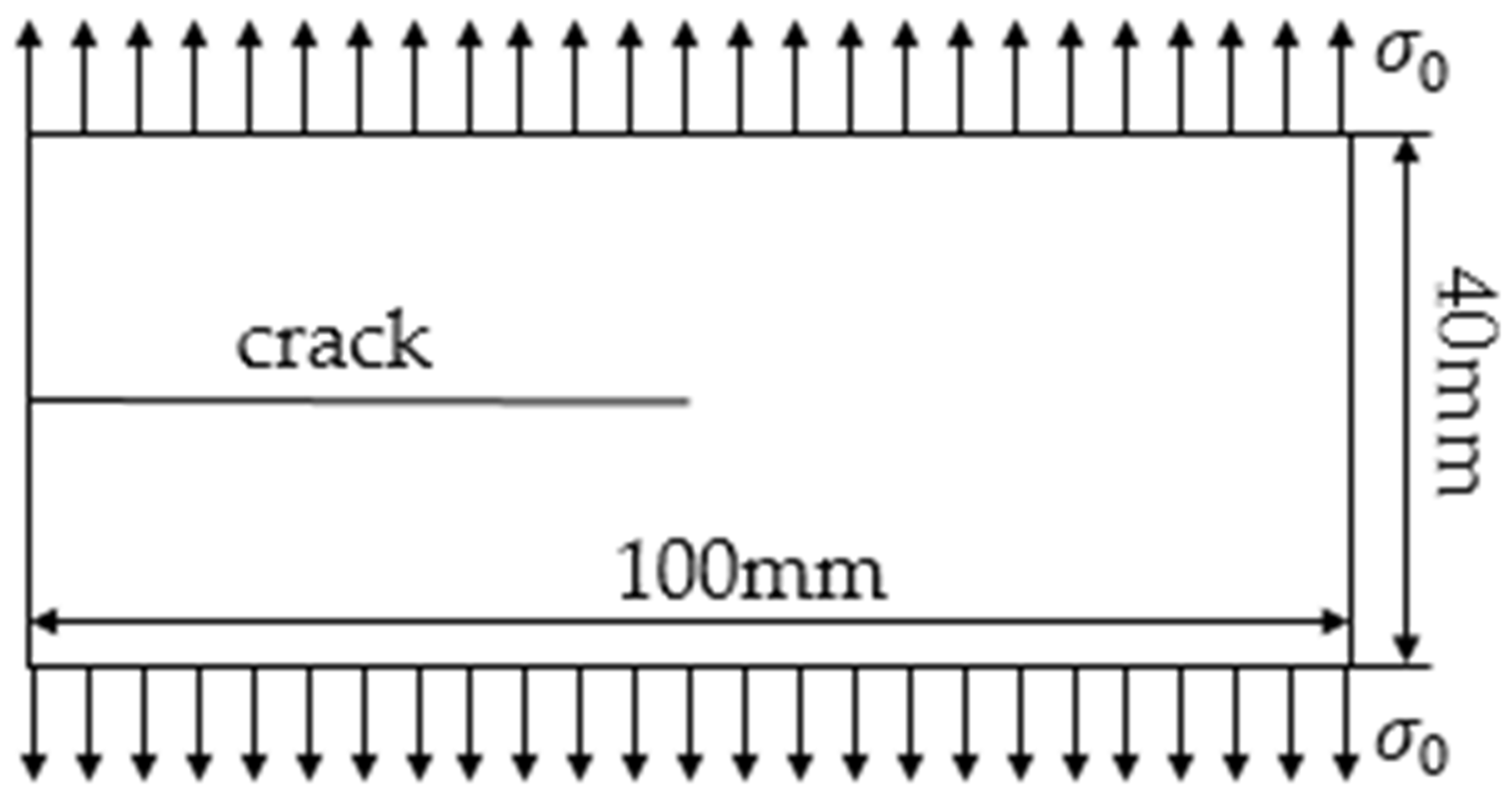
3.1. Cantilever Beam under Uniform Tension
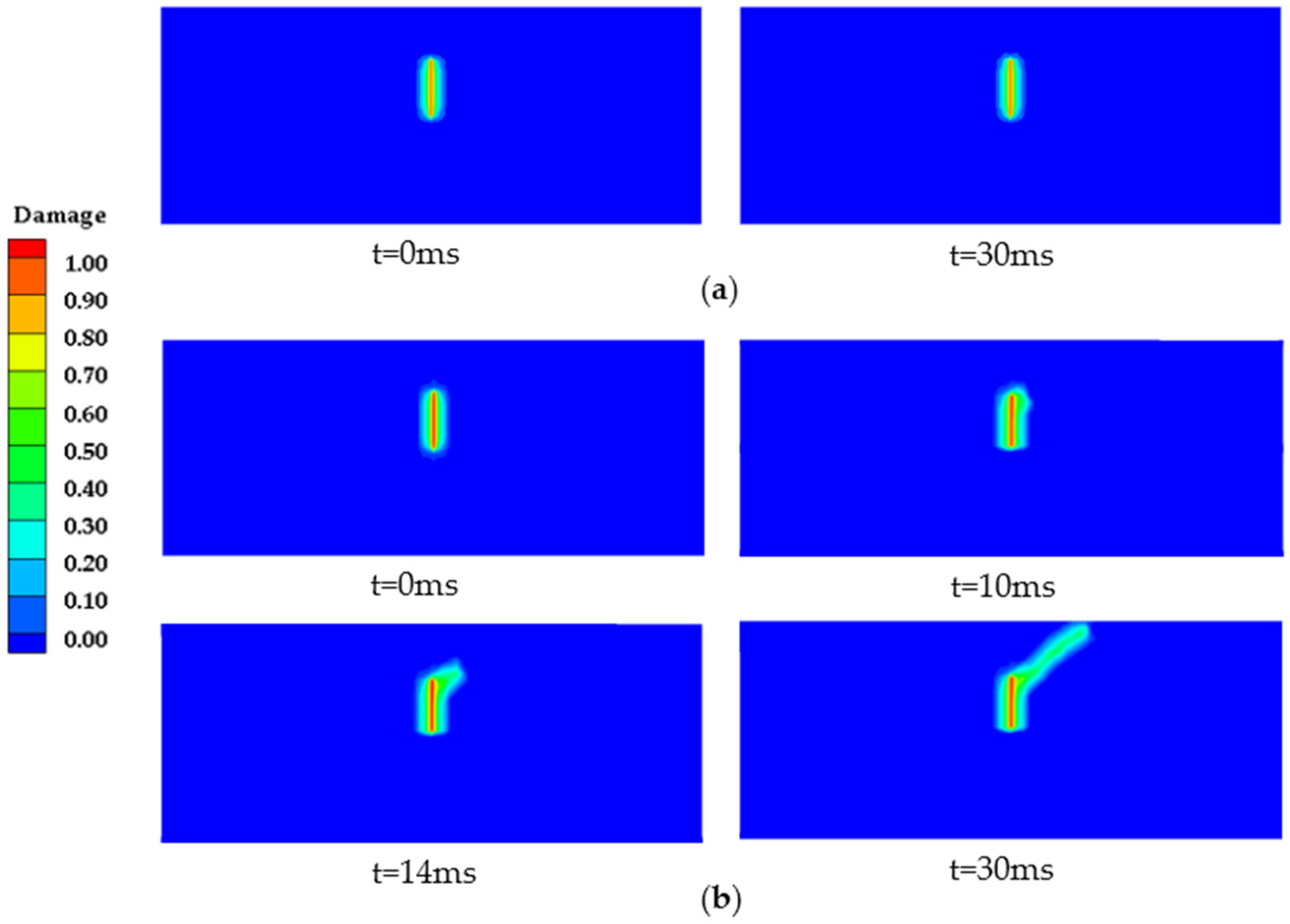
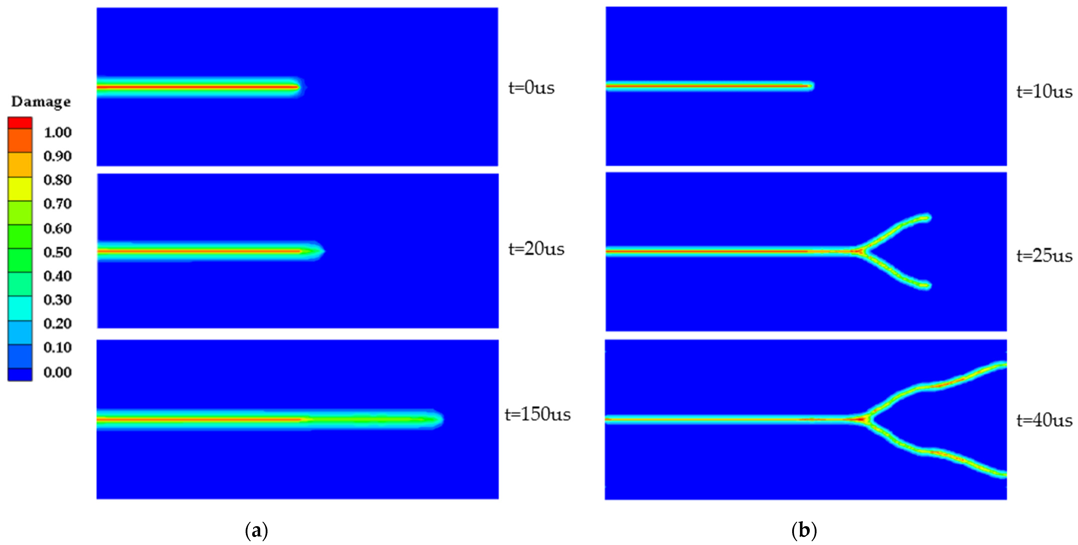
3.2. Dynamic Crack Branching Verification
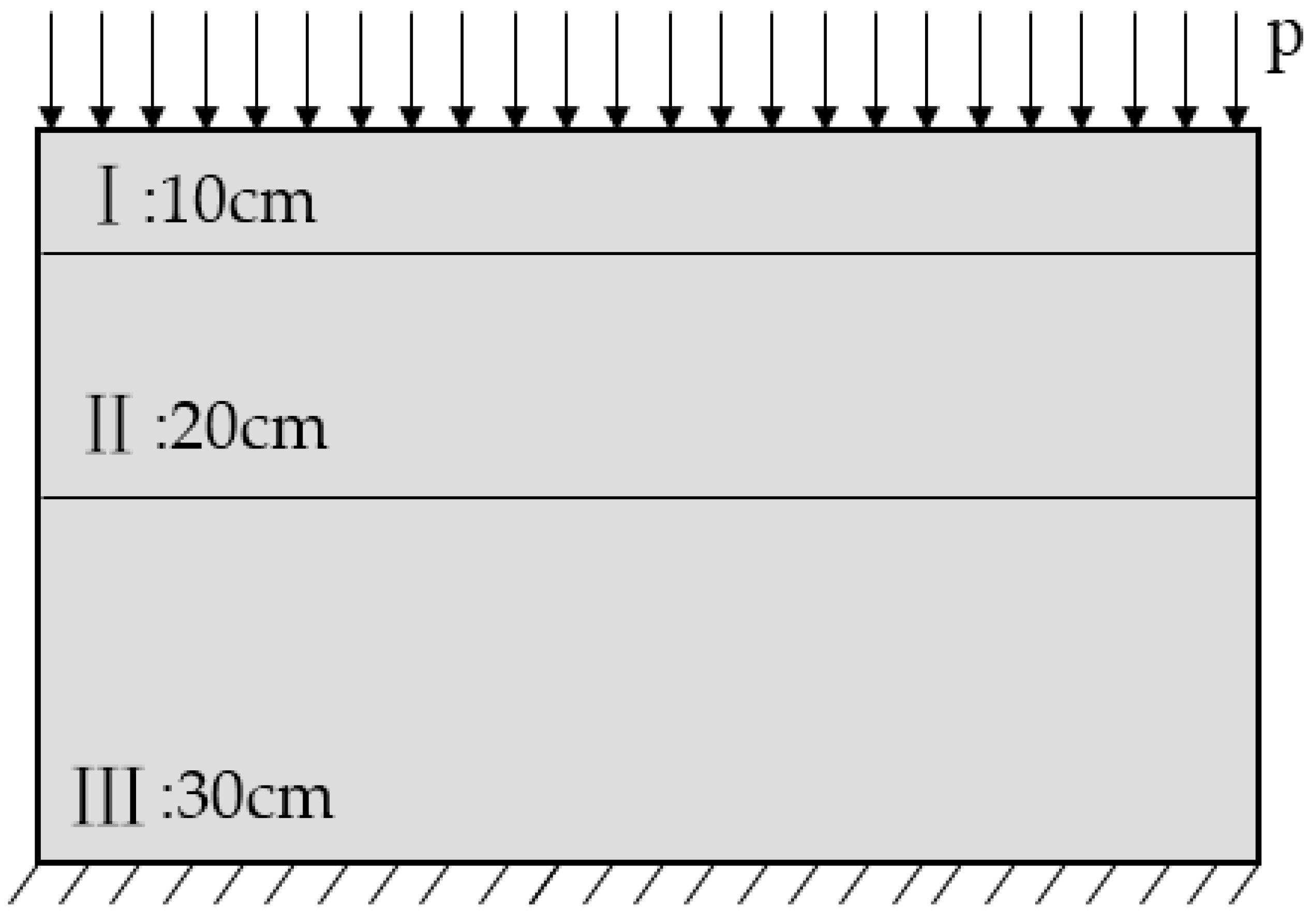
3.3. Multilayer Structure Model
4. Pavement Simulation Model
- Each structural layer of the road surface is a homogeneous and linear elastomer;
- The contact condition between pavement structure layers is completely continuous;
- There is no load transfer capacity between cracks;
- The deformation of the pavement structure is small, and the gravity of each structural layer is not considered.
4.1. Constitutive Relationship of Asphalt Mixture
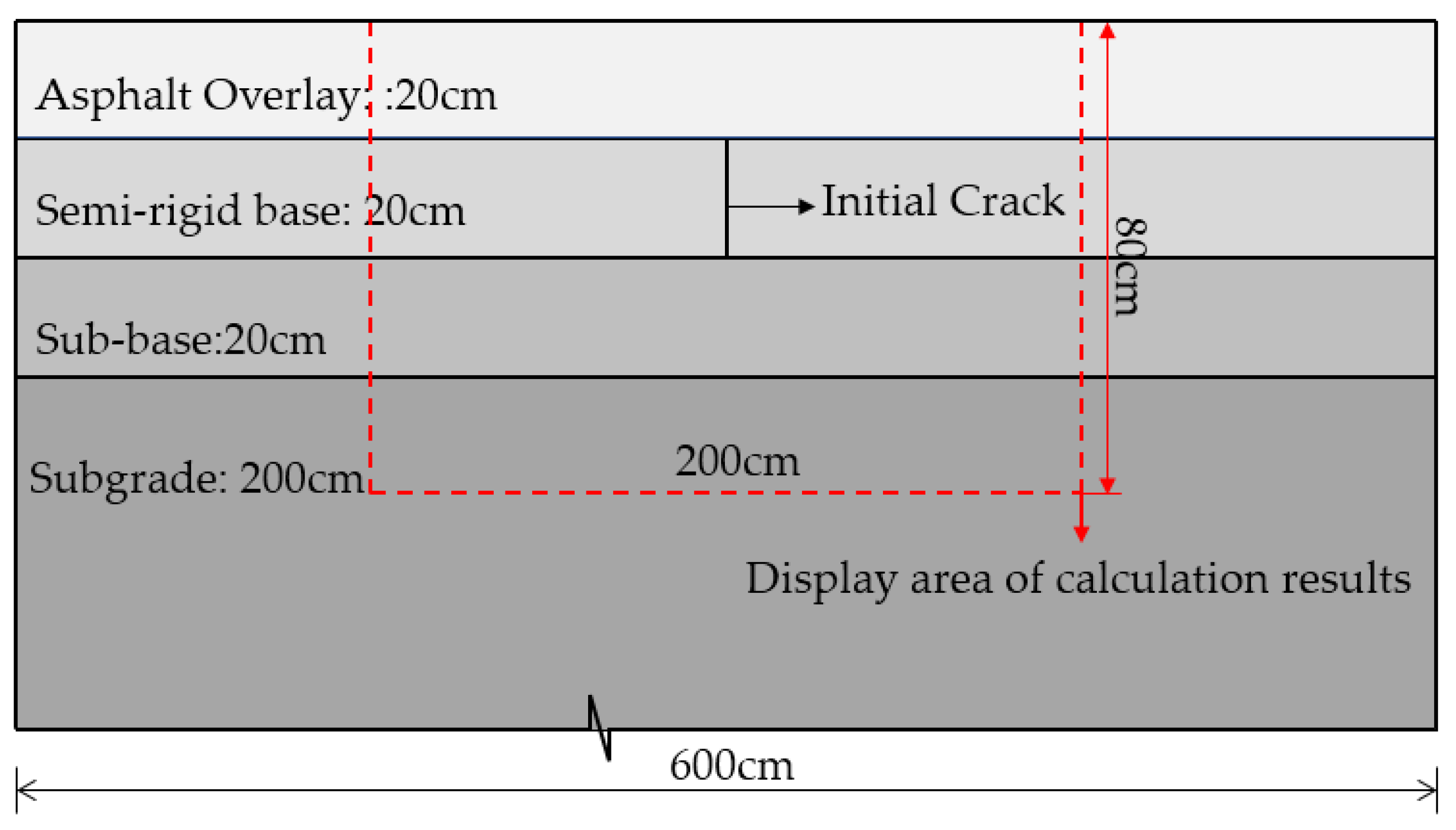
4.2. Pavement Structure Design
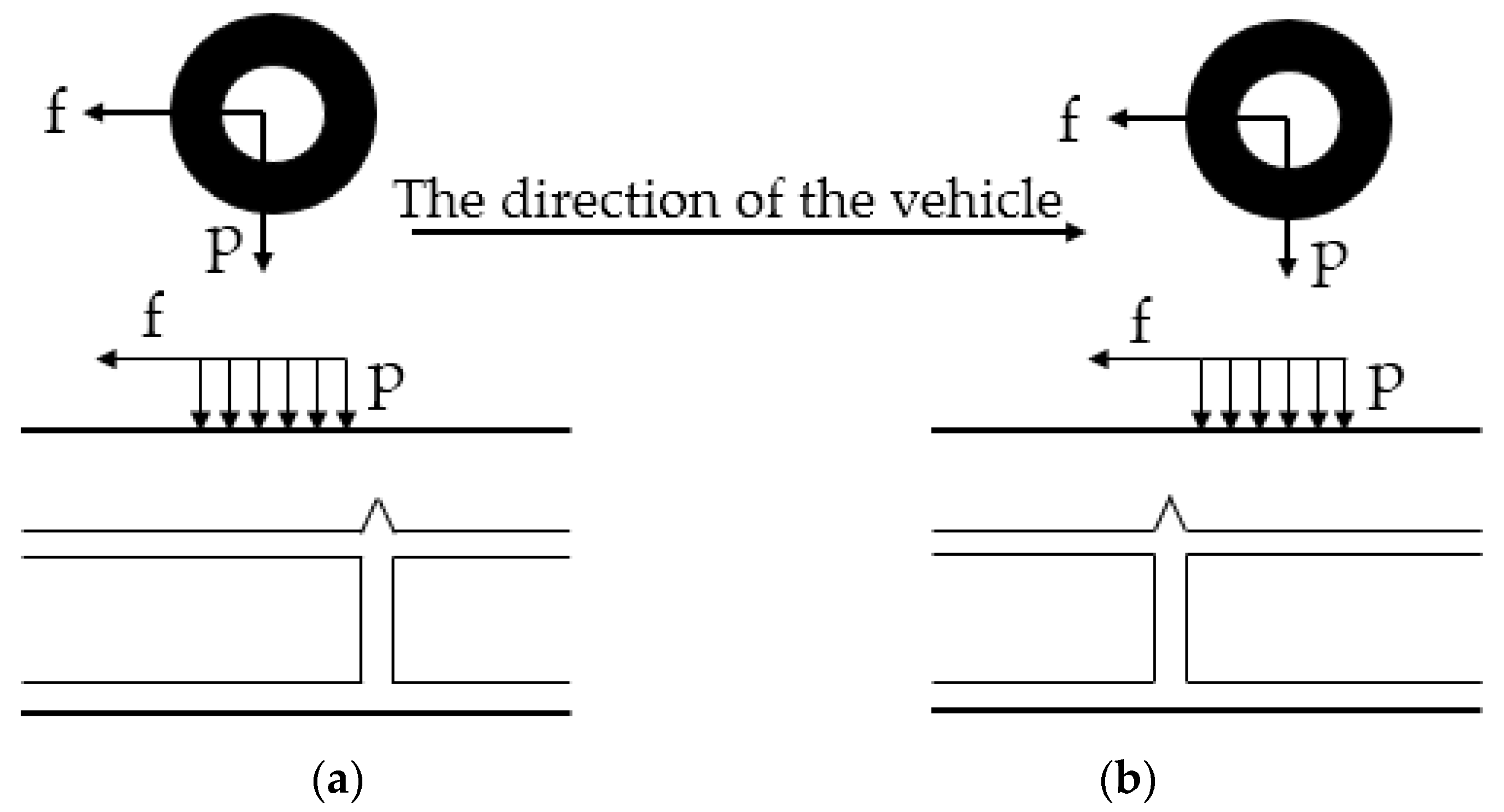
4.3. Analysis of Vehicle Load Action Form
4.4. Influence of Asphalt Surface Thickness
4.5. Influence of Friction
5. Conclusions
- A two-dimensional asphalt pavement delamination model was established by modifying the theory of PD. The simulation results of the proposed model-based PD theory are in good agreement with the analytical solution, experimental results, and finite element calculation results. The feasibility of the application of the model to asphalt pavement structures was verified. It provided a new analytical idea for simulating reflective crack propagation.
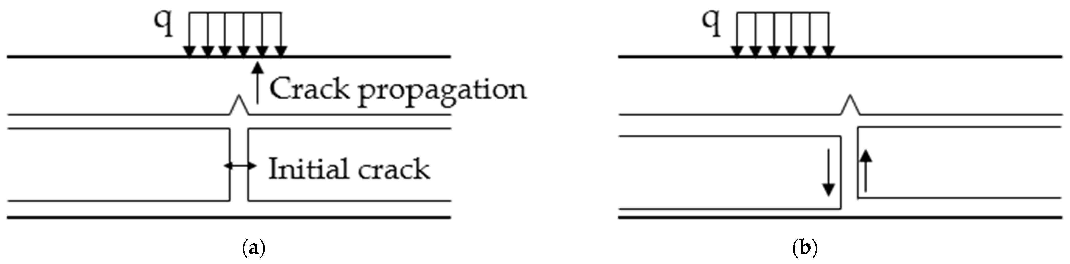
- The propagation of original cracks in the base under different forms of load was compared. The results show that the influence of asymmetric loading on crack propagation is greater than that of symmetric loading.
- The crack propagation features of asphalt surfaces with different thicknesses were summarized through PD simulation results. That is, the increase in the thickness of the asphalt overlay can delay the time of initial crack propagation, slow the crack propagation speed, and weaken the damage degree of the pavement structure. In addition, maintaining a good bond between the semi-rigid base and asphalt overlay can slow the propagation of reflective cracks.
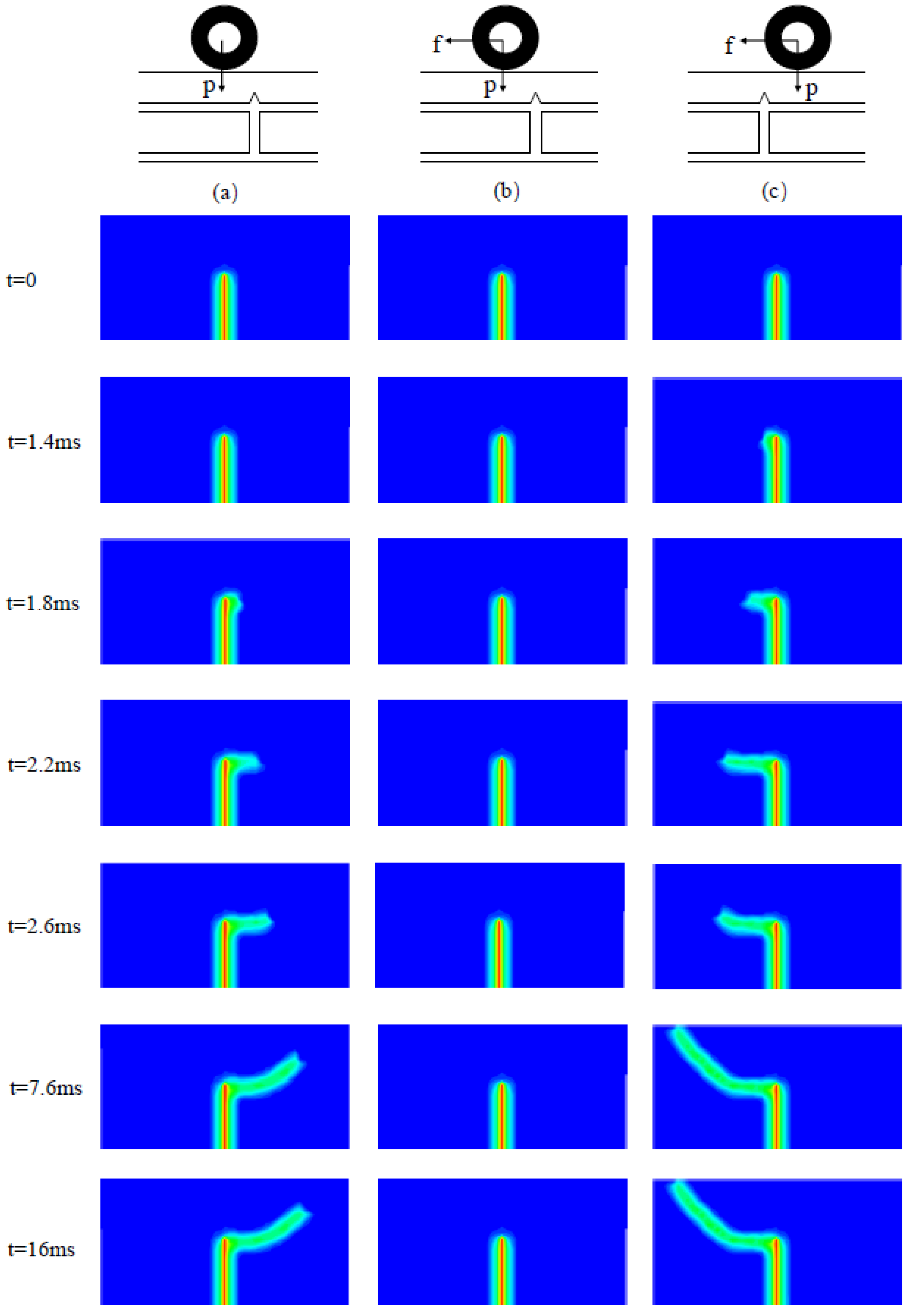
- The influence of friction between tires and roads on reflective crack propagation cannot be ignored. If the friction direction is consistent with the crack propagation direction, the crack propagation will be accelerated. In contrast, crack propagation will be inhibited. The most unfavorable load position is the asymmetrical load position when the vehicle is far from the crack.
Author Contributions
Funding
Institutional Review Board Statement
Informed Consent Statement
Data Availability Statement
Conflicts of Interest
References
- Dong, Z.; Ni, F. Dynamic model and criteria indices of semi-rigid base asphalt pavement. Int. J. Pavement Eng. 2014, 15, 854–866. [Google Scholar] [CrossRef]
- Li, J.; Zi, J.; Jiang, T.; Hu, T.; Feng, Z. Impact of the implementation of continuous construction method on pavement cracking performance. Int. J. Pavement Eng. 2016, 17, 201–210. [Google Scholar] [CrossRef]
- Ann Myers, L.; Roque, R.; Birgisson, B. Propagation Mechanisms for Surface-Initiated Longitudinal Wheelpath Cracks. Transp. Res. Rec. J. Transp. Res. Board. 2001, 1778, 113–122. [Google Scholar] [CrossRef]
- García, I.G.; Carter, B.J.; Ingraffea, A.R.; Mantic, V. A numerical study of transverse cracking in cross-ply laminates by 3D finite fracture mechanics. Compos. Part B Eng. 2016, 95, 475–487. [Google Scholar] [CrossRef]
- Molenaar, A. Evaluation of pavement structure with emphasis on reflective cracking. In Proceedings of the 2nd International RILEM Conference–Reflective Cracking in Pavements: State of the Art and Design Recommendations, Liege, Belgium, 10–12 March 1993; Volume 20, pp. 21–48. [Google Scholar]
- Millien, A.; Dragomir, M.L.; Wendling, L.; Petit, C.; Iliescu, M. Geogrid Interlayer Performance in Pavements: Tensile-Bending Test for Crack Propagation. In 7th RILEM International Conference on Cracking in Pavements; Springer: Dordrecht, The Netherlands, 2012; pp. 1209–1218. [Google Scholar] [CrossRef]
- Chen, D.H.; Hong, F.; Zhou, F. Premature Cracking from Cement-Treated Base and Treatment to Mitigate Its Effect. J. Perform. Constr. Facil. 2011, 25, 113–120. [Google Scholar] [CrossRef]
- Alae, M.; Ling, M.; Haghshenas, H.F.; Zhao, Y. Three-dimensional finite element analysis of top-down crack propagation in asphalt pavements. Eng. Fract. Mech. 2021, 248, 107736. [Google Scholar] [CrossRef]
- Tvergaard, V. Crack growth predictions by cohesive zone model for ductile fracture. J. Mech. Phys. Solids. 2001, 49, 2191–2207. [Google Scholar] [CrossRef]
- Moës, N.; Dolbow, J.; Belytschko, T. A finite element method for crack growth without remeshing. Int. J. Numer. Methods Eng. 1999, 46, 131–150. [Google Scholar] [CrossRef]
- Li, L.K.; Zhou, Y.T.; Cao, P.; Wang, Y.N. Analysis of Ultimate Load-Bearing Capacity for Dowel Bar System in Rigid Pavement Based on XFEM. Appl. Mech. Mater. 2013, 444–445, 961–965. [Google Scholar] [CrossRef]
- Lancaster, I.M.; Khalid, H.A.; Kougioumtzoglou, I.A. Extended FEM modeling of crack propagation using the semi-circular bending test. Constr. Build. Mater. 2013, 48, 270–277. [Google Scholar] [CrossRef]
- Wang, X.; Li, K.; Zhong, Y.; Xu, Q. Investigation of Thermal Reflective Cracking in Asphalt Pavement Using XFEM Coupled with DFLUX Subroutine and FILM Subroutine. Arab. J. Sci. Eng. 2018, 44, 4795–4805. [Google Scholar] [CrossRef]
- Wang, X.; Li, K.; Zhong, Y.; Xu, Q.; Li, C. XFEM simulation of reflective crack in asphalt pavement structure under cyclic temperature. Constr. Build. Mater. 2018, 189, 1035–1044. [Google Scholar] [CrossRef]
- Wang, X.; Zhong, Y. Reflective crack in semi-rigid base asphalt pavement under temperature-traffic coupled dynamics using XFEM. Constr. Build. Mater. 2019, 214, 280–289. [Google Scholar] [CrossRef]
- Silling, S.A. Reformulation of elasticity theory for discontinuities and long-range forces. J. Mech. Phys. Solids 2000, 48, 175–209. [Google Scholar] [CrossRef] [Green Version]
- Silling, S.A.; Askari, E. A meshfree method based on the peridynamic model of solid mechanics. Comput. Struct. 2005, 83, 1526–1535. [Google Scholar] [CrossRef]
- Silling, S.A.; Epton, M.; Weckner, O.; Xu, J.; Askari, E. Peridynamic States and Constitutive Modeling. J. Elast. 2007, 88, 151–184. [Google Scholar] [CrossRef] [Green Version]
- Demmie, P.; Silling, S. An approach to modeling extreme loading of structures using peridynamics. J. Mech. Mater. Struct. 2007, 2, 1921–1945. [Google Scholar] [CrossRef] [Green Version]
- Ha, Y.D.; Bobaru, F. Characteristics of dynamic brittle fracture captured with peridynamics. Eng. Fract. Mech. 2011, 78, 1156–1168. [Google Scholar] [CrossRef]
- Huang, D.; Zhang, Q.; Qiao, P. Damage and progressive failure of concrete structures using non-local peridynamic modeling. Sci. China Technol. Sci. 2011, 54, 591–596. [Google Scholar] [CrossRef]
- Gu, X.; Zhang, Q.; Huang, D.; Yv, Y. Wave dispersion analysis and simulation method for concrete SHPB test in peridynamics. Eng. Fract. Mech. 2016, 160, 124–137. [Google Scholar] [CrossRef]
- Wu, P.; Yang, F.; Chen, Z.; Bobaru, F. Stochastically homogenized peridynamic model for dynamic fracture analysis of concrete. Eng. Fract. Mech. 2021, 253, 107863. [Google Scholar] [CrossRef]
- Peng, R.; Qiu, W.; Jiang, M. Application of a micro-model for concrete to the simulation of crack propagation. Theor. Appl. Fract. Mech. 2021, 116, 103081. [Google Scholar] [CrossRef]
- Liu, W.; Yan, K.; Li, J.Q.; Yang, S. Peridynamics-based simulation of semi-circular bending (SCB) testing. Constr. Build. Mater. 2020, 268, 121190. [Google Scholar] [CrossRef]
- Ruan, L.; Luo, R.; Wang, B.; Yu, X. Morphological characteristics of crack branching in asphalt mixtures under compression. Eng. Fract. Mech. 2021, 253, 107884. [Google Scholar] [CrossRef]
- Ruan, L.; Luo, R.; Zhang, D.; Wang, B. Numerical simulation of crack paths in asphalt mixture using ordinary state-based peridynamics. Mater. Struct. 2021, 54, 90. [Google Scholar] [CrossRef]
- Ha, Y.D.; Bobaru, F. Studies of dynamic crack propagation and crack branching with peridynamics. Int. J. Fract. 2010, 162, 229–244. [Google Scholar] [CrossRef] [Green Version]
- Ban, H.; Im, S.; Kim, Y.-R.; Jung, J.S. Laboratory tests and finite element simulations to model thermally induced reflective cracking of composite pavements. Int. J. Pavement Eng. 2017, 19, 220–230. [Google Scholar] [CrossRef]
- Dave, E.V.; Buttlar, W.G. Thermal reflective cracking of asphalt concrete overlays. Int. J. Pavement Eng. 2010, 11, 477–488. [Google Scholar] [CrossRef]
- Yoo, P.J.; Al-Qadi, I.L.; Elseifi, M.A.; Janajreh, I. Flexible pavement responses to different loading amplitudes considering layer interface condition and lateral shear forces. Int. J. Pavement Eng. 2006, 7, 73–86. [Google Scholar] [CrossRef]
- Liu, W. Numerical Simulation of Semi-Circular Bending Experiment of Asphalt Mixture at Low Temperature with Peridynamics Theory. Master’s Thesis, Hunan University, Changsha, China, 2018. [Google Scholar]
- Shen, Q. Research on Reflective Crack Fatigue Propagation of Asphalt Pavements with Semi-Rigid Base Course Based on XFEM. Master’s Thesis, Hunan University, Changsha, China, 2018. [Google Scholar]
- Shen, F.; Zhang, Q.; Huang, D. Damage and Failure Process of Concrete Structure under Uniaxial Compression Based on Peridynamics Modeling. Math. Probl. Eng. 2013, 2013, 631074. [Google Scholar] [CrossRef]
- Walter, G.; Nicolas, S.; Eduardo, A. Micropolar peridynamic constitutive model for concrete. In Proceedings of the 19th International Conference on Structural Mechanics in Reactor Technology (SMiRT19), Toronto, ON, Canada, 12–17 August 2007; pp. 12–17. [Google Scholar]
- Nicolas, S. Peridynamic Modeling of Quasibrittle Structures; The University of New Mexico: Albuquerque, NM, USA, 2008. [Google Scholar]
- Deng, Y.; Luo, X.; Gu, F.; Zhang, Y.; Lytton, R.L. 3D simulation of deflection basin of pavements under high-speed moving loads. Constr. Build. Mater. 2019, 226, 868–878. [Google Scholar] [CrossRef]
- Sui, X.; Cao, L.; Ma, X.; Wang, H.; Dong, Z. Research on transversely isotropic permeability of asphalt pavement: Laboratory tests and computational simulation. Constr. Build. Mater. 2020, 251, 118958. [Google Scholar] [CrossRef]
- Highway Research Institute, Ministry of Transport. JTG D50-2017 Code for Design of Highway Asphalt Pavement; People’s Communications Press: Beijing, China, 2017. [Google Scholar]
- Zhuang, J.D. Computational Vehicle Ground Mechanics; China Machine Press: Beijing, China, 2002; pp. 52–65. [Google Scholar]
- Ministry of Communications of the People’s Republic of China. Industrial Standard of the People’s Republic of China, Code for Design of Highway Asphalt Pavement (JTG D50-2017); People’s Communications Press: Beijing, China, 2017. [Google Scholar]
- Sun, Y.; Zhai, X.; Li, N. Analysis on Propagation Mechanism of Asphalt Pavement Reflective Crack and Anti-Cracking Effect. J. Shenyang Jianzhu Univ. (Nat. Sci. Ed.) 2012, 28, 1023–1029. [Google Scholar]


| Expression of the Micromodulus | Poisson’s Ratio | Micromodulus | |
|---|---|---|---|
| Plane strain (2D) | |||
| Plane stress (2D) | |||
| 3D |
| Elastic Modulus | Poisson’s Ratio | |
|---|---|---|
| I | 2000 MPa | 1/3 |
| II | 1500 MPa | 1/3 |
| III | 1300 MPa | 1/3 |
| Pavement Structure | Modulus (MPa) | Poisson’s Ratio | Density(kg/m3) | Fracture Energy (J/m2) |
|---|---|---|---|---|
| Asphalt overlay | 3000 | 1/3 | 2300 | 1500 |
| Semi-rigid base | 2800 | 1/3 | 2200 | 980 |
| Subbase | 2200 | 1/3 | 2100 | 980 |
| Soil base | 60 | 1/3 | 1800 | / |
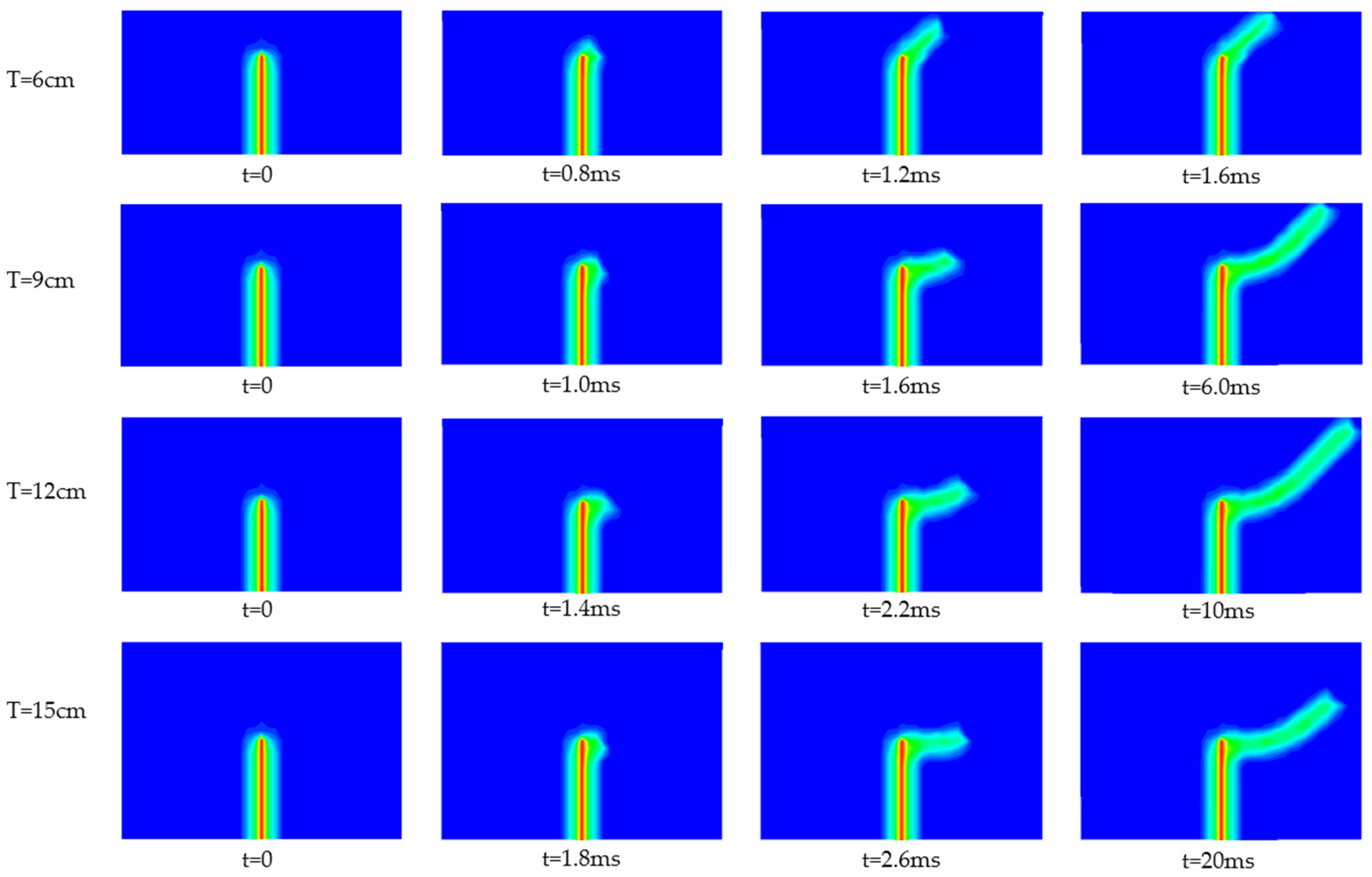
| Thickness of Asphalt Overlay | Expansion Behavior of Reflective Cracks |
|---|---|
| T = 6 cm | At t = 0.8 ms, the initial cracks in the semi-rigid base begin to expand and spread along the upward sloping direction, and run through the asphalt overlay at t = 1.6 ms. |
| T = 9 cm | At t = 1.0 ms, the initial cracks begin to extend horizontally along the interface between semi-rigid base and asphalt overlay. At t = 1.6 ms, the fracture propagation direction changes and begins to extend upward at a certain angle to the base. At t = 6.0 ms, cracks run through the asphalt overlay. |
| T = 12 cm | At t = 1.4 ms, the initial cracks begin to extend horizontally. It changes and begins to expand along the upward sloping direction at t = 2.2 ms. At t = 10 ms, cracks run through the asphalt overlay. |
| T = 15 cm | At t = 1.8 ms, the initial cracks begin to extend horizontally. It changes and begins to expand along the upward sloping direction at t = 2.6 ms. At t = 20 ms, the structure is stable and the crack does not run through the asphalt overlay. |
Publisher’s Note: MDPI stays neutral with regard to jurisdictional claims in published maps and institutional affiliations. |
© 2022 by the authors. Licensee MDPI, Basel, Switzerland. This article is an open access article distributed under the terms and conditions of the Creative Commons Attribution (CC BY) license (https://creativecommons.org/licenses/by/4.0/).
Share and Cite
Shi, Z.; Yue, J.; Xu, L.; Wang, X. Peridynamics for Fracture Analysis of Reflective Cracks in Semi-Rigid Base Asphalt Pavement. Appl. Sci. 2022, 12, 3486. https://doi.org/10.3390/app12073486
Shi Z, Yue J, Xu L, Wang X. Peridynamics for Fracture Analysis of Reflective Cracks in Semi-Rigid Base Asphalt Pavement. Applied Sciences. 2022; 12(7):3486. https://doi.org/10.3390/app12073486
Chicago/Turabian StyleShi, Zhichuang, Jinchao Yue, Lingling Xu, and Xiaofeng Wang. 2022. "Peridynamics for Fracture Analysis of Reflective Cracks in Semi-Rigid Base Asphalt Pavement" Applied Sciences 12, no. 7: 3486. https://doi.org/10.3390/app12073486
APA StyleShi, Z., Yue, J., Xu, L., & Wang, X. (2022). Peridynamics for Fracture Analysis of Reflective Cracks in Semi-Rigid Base Asphalt Pavement. Applied Sciences, 12(7), 3486. https://doi.org/10.3390/app12073486