Article

Early Gapping and Platoon Merging Strategies for Autonomous Vehicles using Local Controllers

Department of Mechanical Engineering and Mechatronics, Ariel University, Ariel 44837, Israel
*
Author to whom correspondence should be addressed.
Appl. Sci. 2022, 12(13), 6328; https://doi.org/10.3390/app12136328
Submission received: 22 May 2022 / Revised: 18 June 2022 / Accepted: 20 June 2022 / Published: 21 June 2022
(This article belongs to the Special Issue Traffic Prediction and Route Guidance)

Abstract

:
Autonomous vehicle merging schemes require a central control or a complex communication system between the vehicles. We suggest an alternative local traffic control method based on distance sensors and roadside units which provides the vehicles with the desired gap profile without the need for vehicle-to-vehicle communication. The gap profile aims to open gaps between the vehicles before an upcoming junction. To explore the profiles’ governing parameters, 140,000 simulation cases with varying conditions were run. Results show that, for a speed limit of 100 km/h and high inlet density (of 1–1.5 s between vehicles), the best strategy with respect to flow and merging percentage (of ~90%) is to use early gapping and platoon merging using linear profiles with long stabilization sections (>0.6 km). Moreover, the gapping process should start when the vehicle ahead attains a velocity of 75 km/h. In this way, fluent traffic can be sustained without perpetuating upstream traffic jams.

1. Introduction

Merging lanes are common conditions in traffic flow when an obstacle is incorporated along the way or when a ramp road merges into the main lane. Due to the possible impact of merging lanes on the total traffic flow, the topic of traffic flow merging has been studied extensively for manually driven vehicles, using experimental observations [1] and by using simulations or mathematical models such as game theory [2], agent-based simulations [3] and simulations of cooperative lane changing [4].
An intuitive solution for autonomous vehicle (AV) merging requires the establishment of communication between vehicles [5], i.e., the ability of a vehicle to connect with network services, other vehicles and infrastructure [6]. Such technology may also provide real-time information about ongoing traffic conditions [7]. However, obtaining a vehicular communication network requires defined protocols [8] and may be challenging due to network load and loss rate. Vehicular ad hoc networks have failed in their scalability issues and their required resultant communication overhead. They do not address the time required for a vehicle to verify all message signatures sent by neighboring vehicles, especially when traffic is dense (where packet length increases due to signatures and public-key certificates). This problem is further increased when considering inter-vehicle communication [9]. Further complications in the physical layer include obstacles, reflections and non-conventional problems emerging as the vehicles change their positions. Therefore, alternative control methods that do not rely solely on vehicle-to-vehicle communication should also be considered.
An alternative approach that does not assume vehicle-to-vehicle communication is based on assignments of predetermined speed profiles to the vehicles. It has been suggested to improve road traffic flow and avoid conflicts in urban driving scenarios [10,11]. Speed profiles are generated using temporal optimization of the timestamps for all waypoints along the given path. These schemes are suited for a small number of vehicle scenarios, as the configuration space grows exponentially with the number of vehicles. In a previous paper [12], we proposed a control scheme in which each vehicle controls its speed according to signals received from roadside units (RSU) and gap measurements to the vehicle ahead. The RSUs convey a predetermined speed profile along the road to optimize the traffic flow of a line of vehicles in the sense of road capacity, energy consumption or vehicle travel duration. No further information is conveyed from the RSU to the vehicles or vice versa.
In this paper, we suggest controlling lane merging control using gap profiles assigned to all the vehicles, based on their position along the road. This is inspired by measurements of speed profiles of human drivers close to intersections [1]. Such measurements reveal different populations of vehicles following different speed patterns, with consistent behavior along the road. For example, under free-flow conditions, for a certain road portion at approximately 200 m away from a forked-road intersection, vehicles start to slow down to 40 km/h, and vehicles heading straight keep their speed at 60 km/h. This implies that there can be an optimal behavioral profile that can be enforced upon AVs during lane merging. The present study aims to explore such location-dependent gap profiles.

Merge Methods

A conventional late zipper merge strategy is often recommended for human-driven vehicles [13,14]. Drivers are guided to use both lanes until reaching the merging area, where they alternate merging in a zipper fashion. The drivers are required to make an abrupt maneuver merge at the lane’s end while maintaining a fair approach for both lanes over time [15], i.e., merging percentages approaches 100%. For human drivers, the zipper method has been shown to considerably reduce speed differences between the two lanes, thus increasing safety. However, it has not been proved to increase throughput [16]. Nishi, Miki [17] used simulations to show the advantages of the zipper method in cases where slow-to-start effects are stronger, i.e., when vehicles acceleration and deceleration are delayed, as occurs with manually driven vehicles. However, regarding cooperative adaptive cruise control on a straight road or a lane change and merge maneuvers, research supports collaborative driving of coupled platoons (or convoys) [18]. However, it conflicts with the zipper merge approach, which forces platoon split.
This study suggests that, when vehicles respond fast, such as in AV, non-zipper methods may achieve higher flow rates and higher merging percentages, assuming the following:
  • When driving as platoons, AVs allow smaller gaps;
  • AVs can merge smoothly by accurately planning and calculating ahead;
  • AVs are obedient and are bound to obey precursory behavioral profiles;
  • AVs are indifferent to fairness on the road.
Here, we aim to examine alternative gap profiles to be imposed upon the AVs on the road to improve traffic flow in the intersection. As mentioned above, such profiles may be implemented using vehicular ad hoc networks. An alternative option is to locate short-range road-side units (RSU) [19] along the lane before the merging position to manage the vehicles’ speed and gap profiles (see Figure 1). Such units only require vehicle-to-infrastructure communication. Their locations are well defined (e.g., proper line-of-sight, distances, etc.), and their signal is specific [9]. In contrast to vehicular ad hoc networks, RSUs are trusted, and their computation capabilities are higher than those of the vehicles.
According to optimal lane reservations for human drivers [20], lane change maneuvers should consider a late merging strategy, i.e., a minimum merging preparation distance [21] in the attempt to increase vehicle road capacity. In this study, it is suggested that, for AVs, the preparation section strongly improves the amount and size of the merging vehicle clusters, thus affecting the percentage of successful merging vehicles. We show that, in contrast to late zipper merging, for AVs, it may be preferable to use early gapping and platoon merging strategies. To this end, we use numerical simulations to investigate how the profile type, gap size, preparation distance before the merging location and vehicle velocity during gapping affect the merging percentage and total traffic flow rate.

2. Methods

2.1. Nomenclature

In this work, a simple discrete-time model was used to simulate traffic flow, similar to the one presented in a previous paper [12]. Throughout the paper, we denote gap, location, speed and acceleration, which relate to the i-th vehicle by gi(t), xi(t), vi(t) and ai(t). The gap gi(t) is the distance between the front end of vehicle i and the back end of vehicle i 1 at time t, as seen in Figure 1. As we desired to set a gap profile, speed and acceleration for each location along the road, we marked the desired merging gap at the merging location by a constant gmerge and the desired gap profile along the road by gd(x), and vi,d(t) and ai,d(t) denote the desired speed and acceleration quantities, where the i-th vehicle is located at time t.

2.2. Gap Profile Method

In this study, we assume that the portion of the road 0 ≤ xL in interest is equipped with RSUs distributed along the road, transmitting to the vehicle receivers the desired gap profile gd(x) at their current location x. RSUs are assumed to be distributed, such that they may enable a realization of sufficiently smooth gap profiles. Specific technological solutions for this are out of the scope of this study.
We assume that the entire line of vehicles in the road (each of length li) drive at speed vs, which we set as the road speed limit. To allow merging, vehicles should open a gap large enough for new vehicles to merge. To increase the gap from the vehicle ahead (vehicle i − 1), the speed of vehicle i must be lower than the speed of vehicle i − 1. The way that vehicle i decelerates is governed by a gap profile, i.e., the deceleration is set according to the desired gd(x). The i-th vehicle at xi(t) compares its current gap:
g i ( t ) = x i 1 ( t ) l i 1 x i ( t )
with the desired gap gd(x = xi). Thus, to acquire gd(x = xi) the required deceleration a i , d ( t ) within a time interval Δt is:
a i ( t ) = 2 ( g i ( t ) g d ( t ) + [ v i 1 ( t ) v i ( t ) ] Δ t ) Δ t 2
The deceleration is limited to the vehicle’s maximal deceleration capabilities (and perhaps also to passenger comfort) and is also limited by the need to maintain a safety gap between vehicles. To prevent collision between the vehicles, the deceleration should also comply with the following safety conditions [22,23,24]:
  • The current gap should be larger than the previous gap, i.e., g i ( t ) > g i ( t Δ t ) .
  • The gap should be larger than a safety gap gs, i.e., g i ( t ) > g s ( v i ( t ) ) .
If one of these conditions is not met, then the following Proportional–Differential (PD) controlled deceleration will be calculated:
a i , c o n t r o l ( t ) = K P [ g i ( t ) g s ( v i ( t ) ) ] + K D g i ( t ) g i ( t Δ t ) Δ t
where KP and KD are the proportional and derivative positive constants, respectively, and g s ( v i ( t ) ) is the safety gap (also known as allowed gap), which changes according to the speed of vehicle i. Equation (3) should suffice in most cases to prevent a collision. Since each vehicle has its mechanical limitations, a uniform safety time gap g s ( v i ( t ) ) = T s · v i ( t ) was used, where Ts is the predefined safety time gap and is measured in seconds (as the two-second rule).
After calculating the control deceleration Equation (3), the deceleration applied is confined to the maximal acceleration and deceleration of the vehicle ai,vehicle:
a i ( t ) = m a x { m i n { a i , d ( t ) , a i , c o n t r o l ( t ) } , a i , v e h i c l e }
More involved control schemes may be considered, but for the sake of simplicity, the above scheme was chosen to demonstrate our suggested approach.
Having ai(t), one can find the speed vi(t + Dt) and the position xi(t + Dt) at the following time step, which must comply with the maximal speed.

2.3. Gap Profile Types

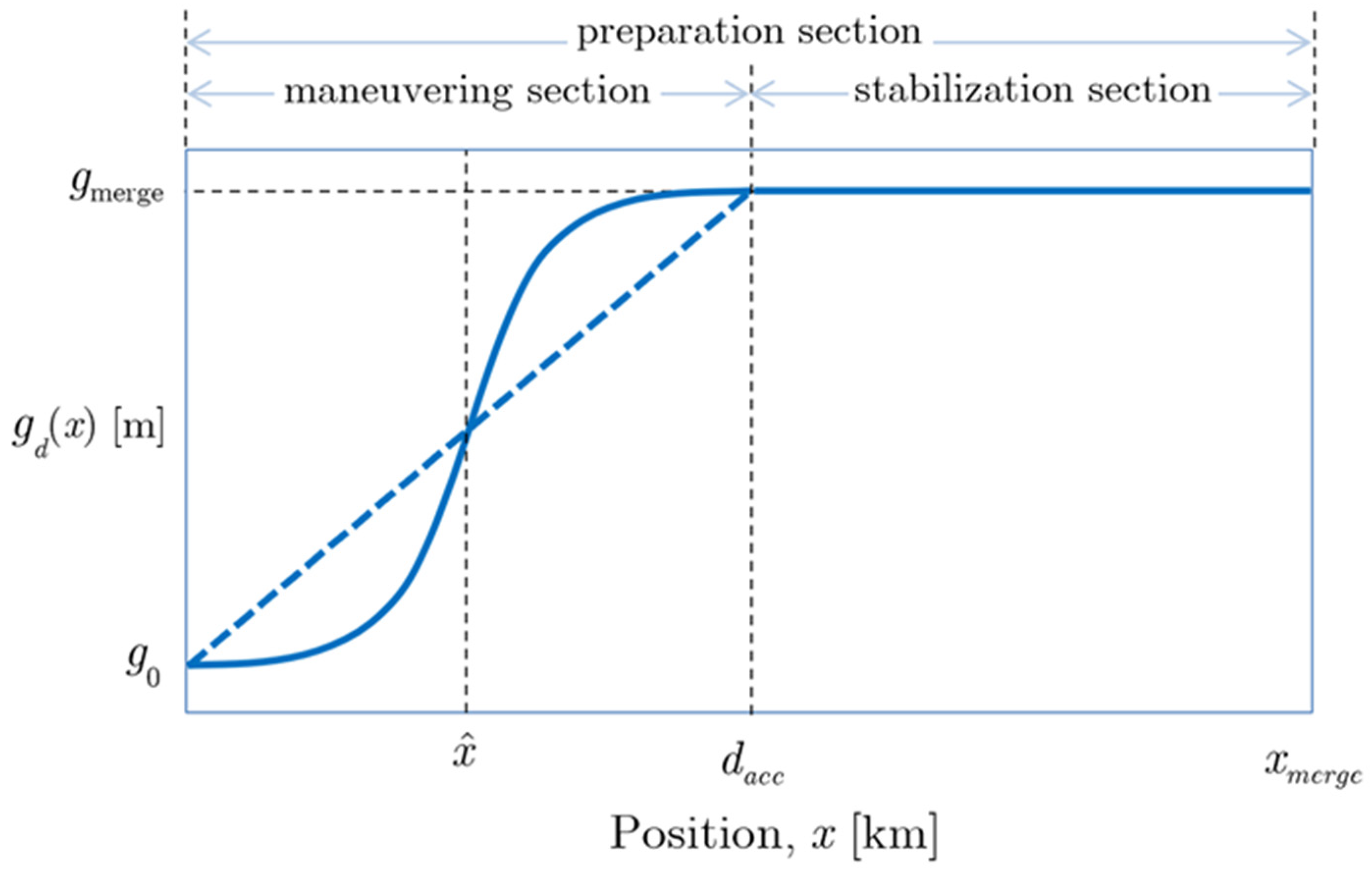
Figure 2 presents a schematic description of the two types of gap profiles gd(x), which we examined. xmerge denotes the preparation section, which ends at the merging point where the desired gap is gmerge. The maneuvering section (dacc) marks the portion of the road where the imposed deceleration occurs, measured from the beginning of the road, with d a c c x m e r g e . The rationale is to allow vehicles to gradually enlarge their gaps from the vehicles ahead while minimizing the need for abrupt braking, preventing motion sickness and phantom jams.
After obtaining the desired gap, the remaining portion of the road, which we denote as stabilization section (dstb), measured from dacc to xmerge, is dedicated to stabilizing the gaps along the vehicle line (i.e., to allow the gained gaps to accumulate and the local controllers to reach a steady state).
When designing the desired gap profiles, it is beneficial to apply optimization methods such as trajectory optimization [10,11] or predictive control methods [25]. As a first approximation, we examine here the gap profiles of two simplified types:
A linear profile (dashed line in Figure 2): The vehicles are required to decelerate and open a gap in a constant manner throughout the maneuvering section:
g d ( x ) = g 0 + ( g m e r g e g 0 ) x d a c c
A sigmoid profile (solid line in Figure 2): Only a portion of the maneuvering section is effectively used for gapping. At the extreme, this resembles a late merge approach with human driver behavior [16,21]. An error function sigmoid was used to construct the sigmoid gap profile:
g d ( x | d a c c , g 0 , g m e r g e ) = g m e r g e + g 0 2 + g m e r g e g 0 2 · erf [ 6 ( x 1 2 d a c c ) d a c c ]
Here, erf(·) denotes the error function.
Note that, if possible, vehicle i opens a gap from the vehicle ahead (i − 1) according to gd(x) and is expected to reach dacc with the desired gap for merging gmerge. These accumulated gaps are distributed between the AVs while driving along the stabilization section to allow a higher merging percentage until reaching the merging point xmerge. After passing the merging point, vehicle i accelerates back to vs, regardless of any profile.
Vehicle i follows the gap profile gd(x) only if the vehicle ahead is above a certain speed, i.e., v i 1 v g a p p i n g . Intuitively, one can suggest making an immediate deceleration to increase the gap, but this may result in phantom upstream jams, as shown for human drivers [26]. Additionally, consecutive vehicles should not try to increase the gap at the same time. Since vehicle i + 1 must follow vehicle i’s speed to prevent a collision, it must decelerate more than that of vehicle i to increase its gap at the same time. In addition, vehicle i + 2 must decelerate even more than vehicle i + 1, and so on; thus, a jam forms. Hence, only once vehicle i − 1 regains vgapping, vehicle i is able to accumulate a gap. If vehicle i − 1 again reduces its speed to lower than vgapping, vehicle i stops the gapping maneuver until vehicle i − 1 regains vgapping. Therefore, to prevent the formation of a braking shockwave, we introduced the “onset gapping speed” vgapping, which is a minimum speed that vehicle i − 1 reaches before the gapping of vehicle i is introduced.
Vehicle i can approximate v i 1 by calculating the change in the distance to vehicle i − 1, measured by vehicle i. Following Equation (1), the way to calculate the speed of the vehicle ahead using the gap measurements over one time step Δ t is according to lim Δ t 0 g i 1 ( t ) g i 1 ( t Δ t ) Δ t = v i 1 ( t Δ t ) v i ( t Δ t ) ) , where the length l i 1 is canceled out. Hence:
v i 1   ( t Δ t ) g i 1 ( t ) g i 1 ( t Δ t ) Δ t + v i ( t Δ t )
This suggests that, when the change in the gap over time is very small, the difference between the current speeds of the two vehicles are also very small, i.e., it is safe to assume that, if g i 1 ( t ) g i 1 ( t Δ t ) 0 , then v i 1 ( t ) v i ( t ) , and if v i ( t ) = v g a p p i n g , then vehicle i starts opening a gap.
A new vehicle can merge only when vehicle i has fully passed the merging point at xmerge and only if there is enough space between the merging point and the next vehicle, i.e., x m e r g e x i + 1 g m e r g e . The merging vehicle enters the lane at the road speed vs with the same density as the main road. Vehicles enter in clusters as large as the gap permits, as shown in a video example of the simulation available at: https://imgur.com/a/9oCZJfJ, (uploaded on 9 August 2020).
Here, we investigate the influence of the inlet density and profile types (linear and error function), the merging position xmerge, the stabilization section size dstb, the gap size gmerge and the onset gapping speed vgapping on the merging percentage and flow.

2.4. Simulation Parameters

To investigate these profiles, we simulated a road section with a line of vehicles, such that each vehicle is equipped with the parameters listed in Table 1.
The masses and lengths of each vehicle were randomly determined. The safe time gap was assumed to be TgTS, TS = 1 s for all vehicles [27,28,29]. All vehicles entered the road at the same initial speed vs = 100 km/h. Inlet vehicle density was introduced based on an initial gap in accordance with the time gap at the entrance Tg(x = 0), when g i ( t = 0 ) = v s T g ( x = 0 ) . All vehicles were given the same maximal acceleration of 3.4 m/s2, as assumed in [30,31,32,33], and the same maximal deceleration of 6.86 m/s2 [30,34]. The scenarios simulated 10 min of traffic with up to 500 vehicles driving. For clarity, we used %dacc and %dstb, which are the relative portions of the maneuvering and stabilization sections from the total preparation section, respectively.
The simulation runs included 10 values of gmerge (taken from 63 m to 153 m), 9 merging positions xmerge (0.2 km to 1.8 km from the beginning of the road), 10 maneuvering ranges (%dacc = 10–100% of xmerge), 2 profiles (linear and error-function), 6 values of vgapping (from 75 km/h to 100 km/h), 13 inlet densities (Tg(x = 0) = 1–2.2 s) and 36 combinations of main and merging lane platoon sizes (1–35 vehicles in platoon) with a preference to the main lane. There were a total of about 140,000 different cases, each simulating a 10 min drive of up to 1000 vehicles in the main lane and an unlimited supply of continuous vehicles flowing in the merging lane (at constant density of (Tg(x = 0) = 1 s).
To measure the effectiveness of the approach with regard to the main lane flow rate, we introduced a parameter Pmerging for the merging success, as follows. For each case, we counted the number of merges that took place and calculated the percentage of new vehicles merging into the road section out of the number of vehicles in the main lane:
P m e r g i n g M e r g i n g   V e h i c l e s P r e s e n t   V e h i c l e s

3. Results

3.1. Vehicle Dynamics in a Position-Time Space

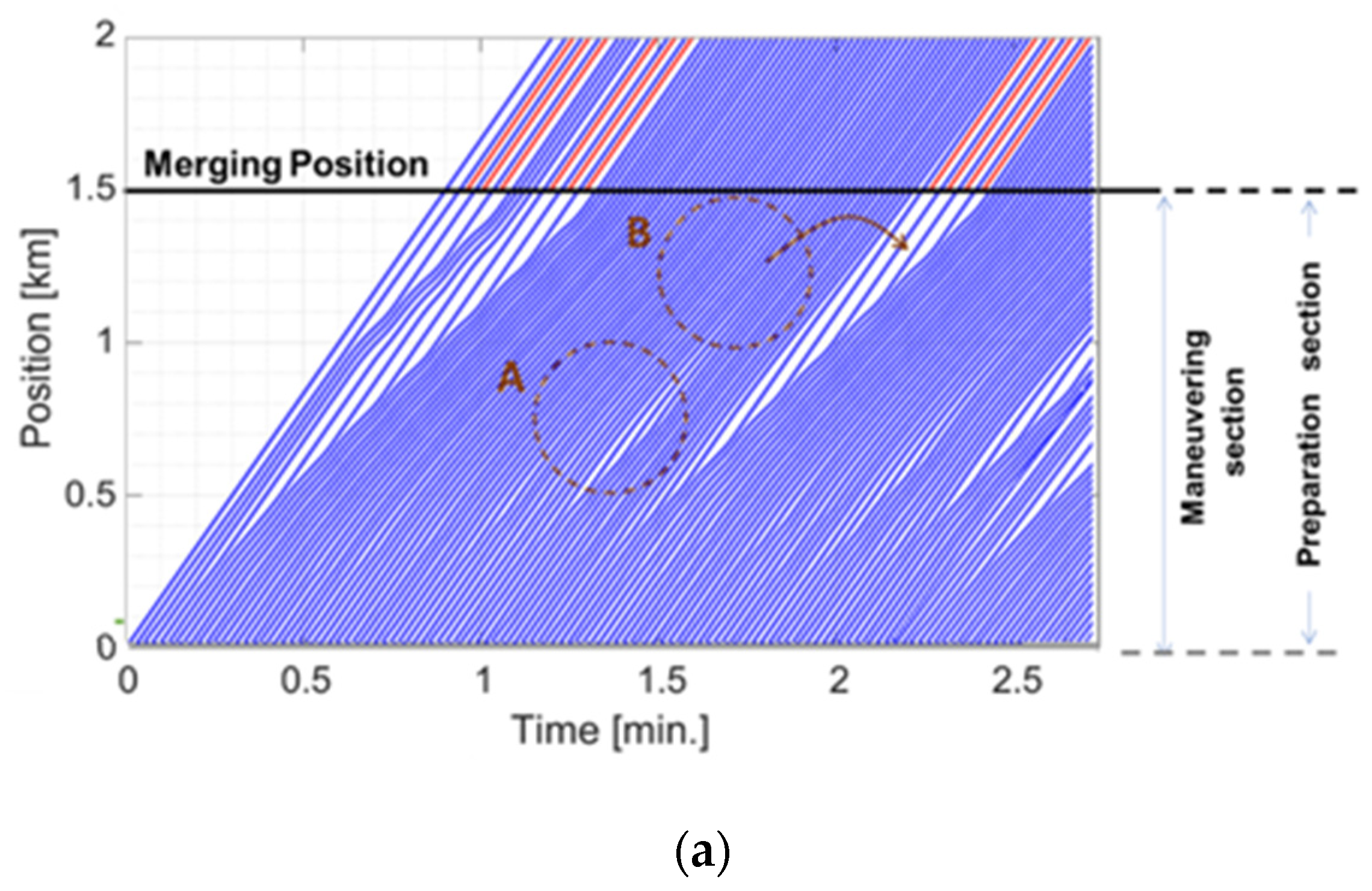
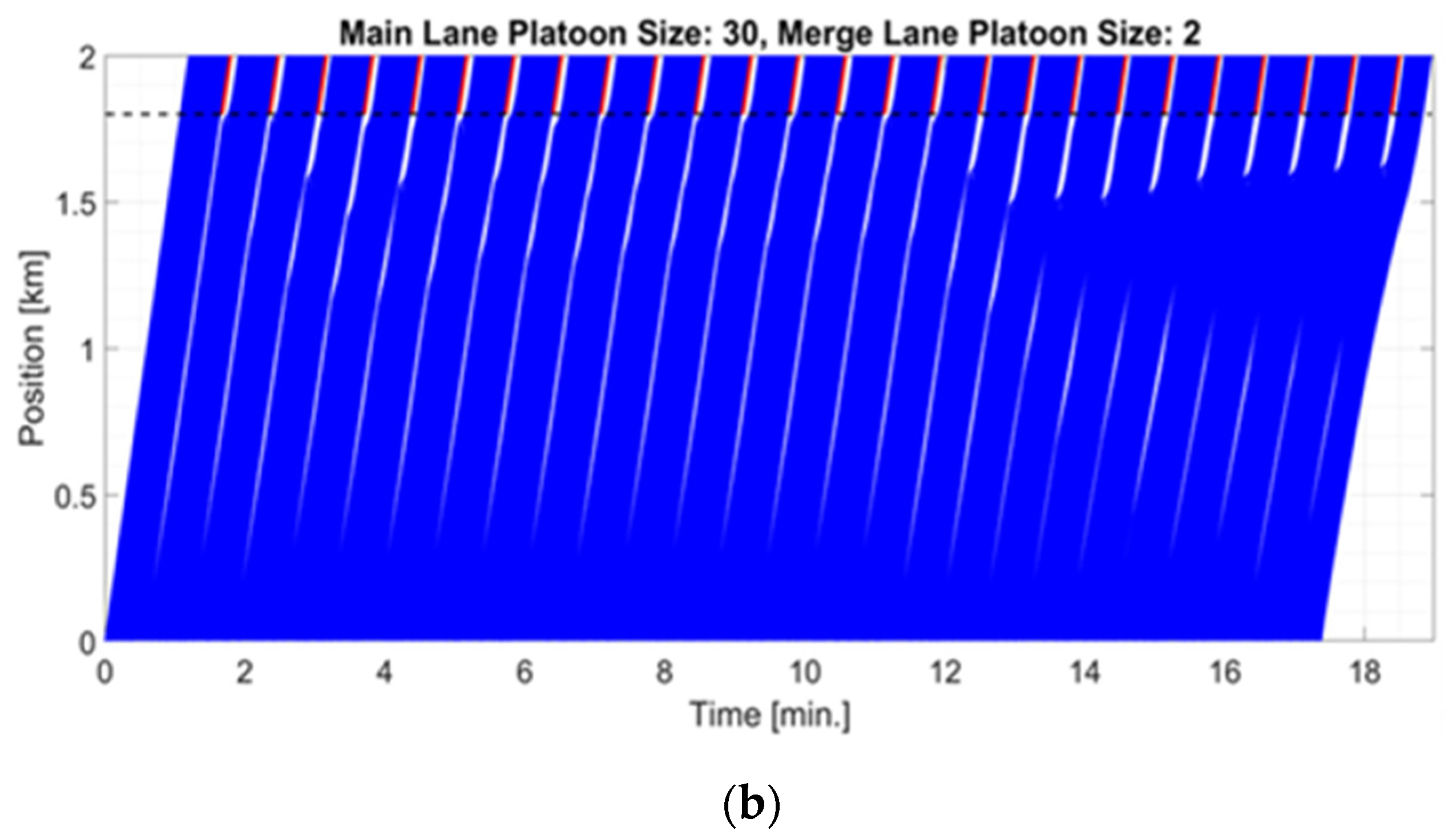
Figure 3 introduces two examples of vehicle dynamics along the road section of the main lane. The positions of the main lane vehicles are presented (with blue lines) as a function of time. Red lines indicate merging vehicles. Figure 3a shows the short-term dynamics (vehicles 1–100 for 3 min) of a case with 10% zipper merging, and Figure 3b shows a longer-term (vehicles 1–800 for 18 min) of a 30:2 platoon size ratio. Note that the vehicles in the preparation section try to comply with the gap profile provided, and accumulated gaps are added up to form platoons with distinguished large gaps between them. This method utilizes fractions of gaps gained during the maneuvering section by contributing them to larger gaps. For example, small gaps marked by circle A in Figure 3a are translated to the larger gap between two dense platoons, leaving vehicles without excessive gaps in B. This optimizes the potential for a larger number of vehicles to merge in each gap and avoids situations where a fraction of gaps is “wasted” without merging vehicles.

3.2. Effect of Inlet Density

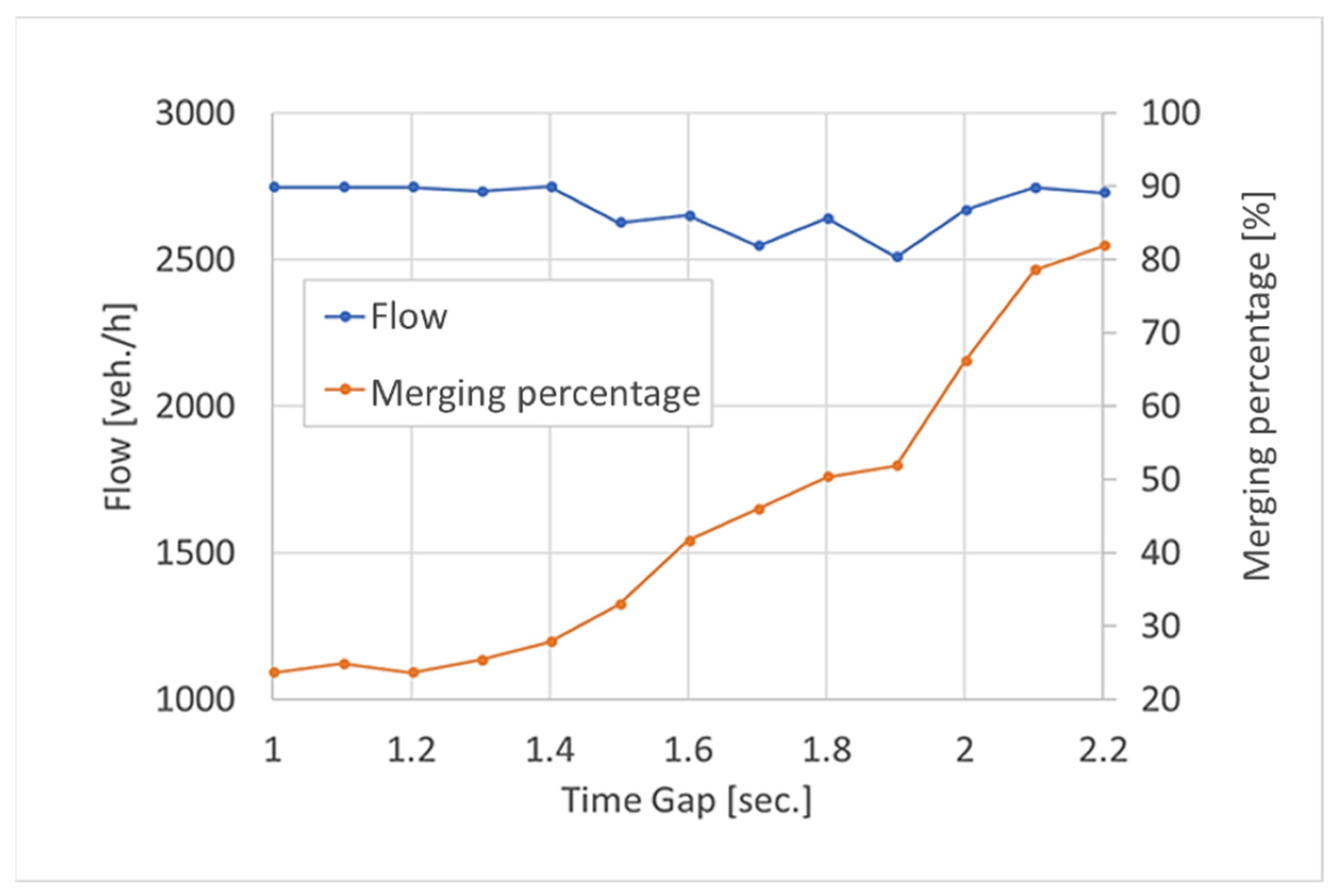
Figure 4 shows the effect of inlet density (Tg(x = 0)) on the merging success and traffic flow (for an example case with xmerge = 1.5 km, %dstb = 5% and vgapping = 90 km/h). In the graph, the x-axis corresponds to inlet density (with Tg(x = 0) between 1–2.2 s). From the graph, it is clear that, for high inlet densities (with Tg(x = 0) = 1–1.5 s), the merging success does not exceed 30% while maintaining a high flow rate of 2700 veh/h. As inlet density reduces (with Tg(x = 0) = 1.5–2.2 s), the merging success increases to up to 82%, and the flow rate remains in the range of 2500–2700 veh/h. In all cases, the algorithm allowed for the controlling of a high flow rate for all the examined densities.
For high inlet density (e.g., rush hour, Tg(x = 0) = 1 s), although the resulting flow is high, the merging success is relatively low (23%). To explore the gapping conditions that allow high flow rates at low merging percentages, we focused on the specific case of (Tg(x = 0) = 1 s) while changing the gap profile parameters.

3.3. Traffic Flow as a Function of Gap Profile

In this section, we present the effect of gap profile parameters on merging success for the case of road velocity vs = 100 km/h and varying onset gap speeds (vgapping) and platoons’ sizes.
Figure 5 presents the obtained vehicle flow rate in the road as a function of merging position (xmerge), maneuvering section size (%dacc) and merging gap (gmerge) for linear (left) and sigmoid (right) gap profiles.
It is well-shown that the most prominent factor in the resulting flow is the merging position. As the preparation section becomes longer, the traffic flow increases (and more vehicles merge). Point A in the sigmoid graph (right) is most related to human drivers’ behavior with a late merge (i.e., late gapping) and zipper strategy, where there is a small preparation section, the gap provided for each vehicle is small, and the gapping is abrupt. It is apparent that for autonomous vehicles, this strategy may be inferior to the other merging possibilities. For example, point C (in both graphs), where the maximal flow is obtained, represents cases with large preparation sections, large gaps for platoon merging and large stabilization sections that enable gap accumulation.
There is a slight benefit to the linear profile over the error function profile in the obtained flow, and therefore, we show only the results for the linear gap profiles. Larger stabilization sections improve the flow rate, as shown by comparing point B to point A, where a smaller maneuvering section indicates a larger stabilization section, which is essential for cases where the gapping is abrupt (i.e., in the sigmoid profile).
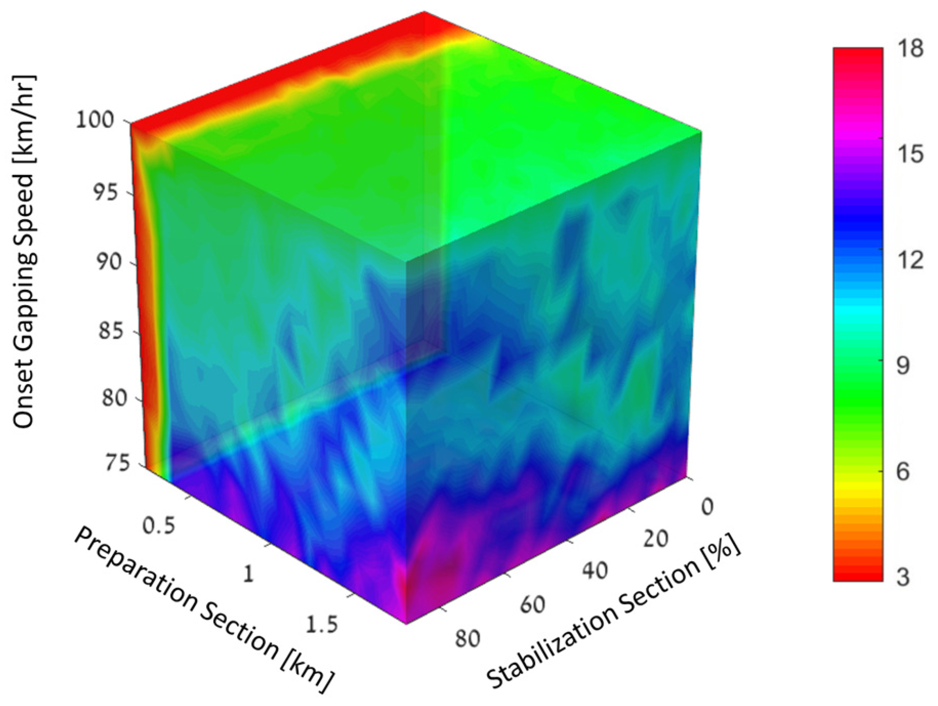
The merging percentage rate increases with the preparation section (xmerge) and with the relative portion of the stabilization section (%dstb), as presented in Figure 6. Lower onset gap speeds result in higher merging percentages as well.

3.4. Merging Success as a Function of Platoon Sizes

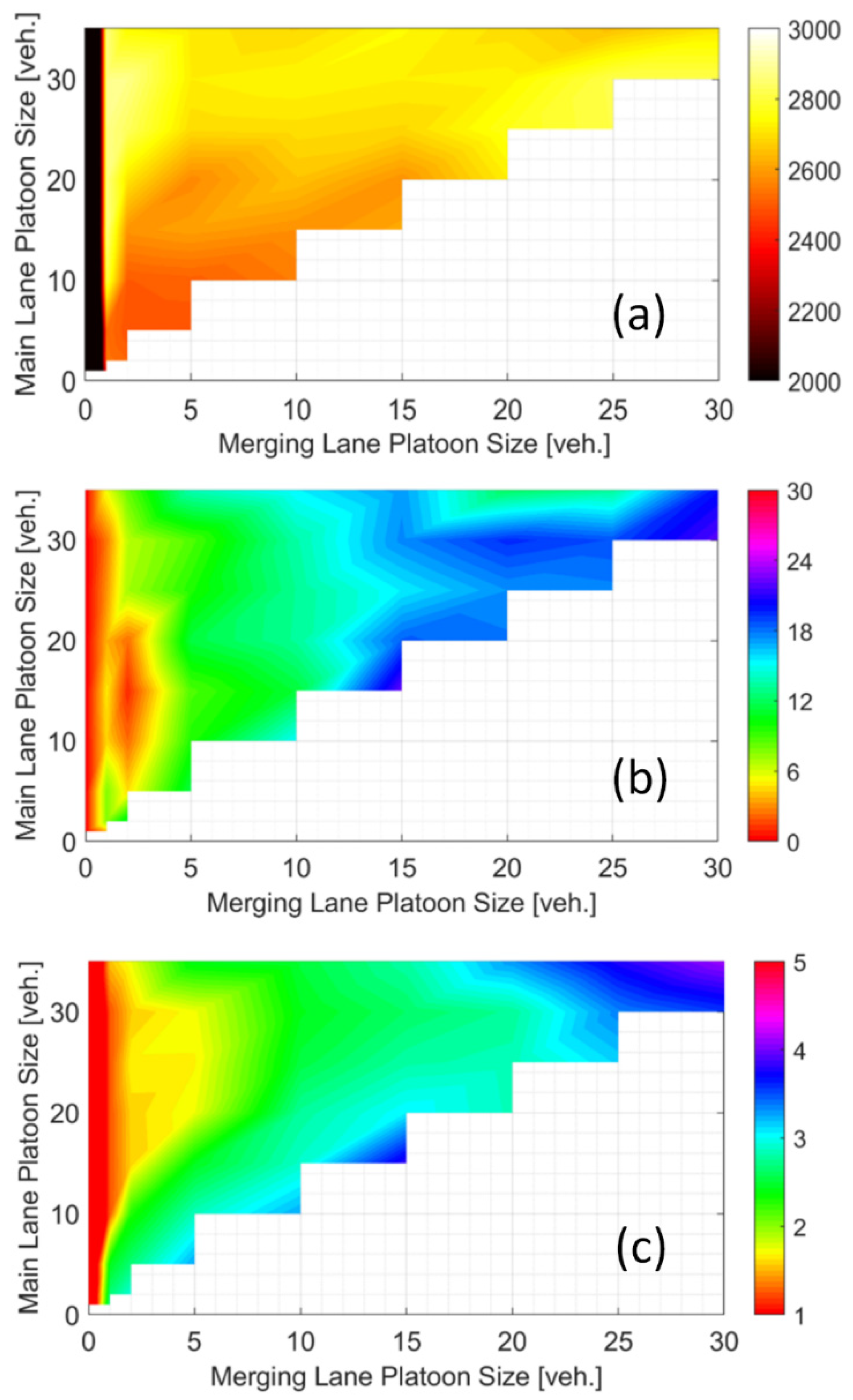
Following the results shown in Figure 5 and Figure 6, we continue the investigation for a linear profile, a preparation section of 75% and gapping onset speeds of 75 km/h. Here, we show the effect of platoon size at the main and at the merging lanes. Figure 7 presents the effect of platoon sizes of merging and main lanes on obtained traffic flow [vel./h] (Figure 7a), on merging success (%) (Figure 7b) and on maximal time duration [min] along the section (Figure 7c).
Higher flow rates are obtained for larger main lane platoons (Figure 7a), and higher merging successes are obtained for larger merging lane platoons (Figure 7b). The duration along the road section (Figure 7c) decreases with the ratio between main-to-merging lane platoon size.
The merging rate is sensitive to the actual dynamics at the merging site. Therefore, it is critical that the vehicles reach the merging position at a specific gmerge and at a specific velocity that provides a better opportunity for a large number of vehicles to smoothly merge in and continue down the road without interference. Therefore, larger gaps are aimed for (and thus a large stabilization section is essential).
There are two main advantages in forming large gaps for multiple vehicles to merge. The first is that both the vehicles from the main lane and the merging vehicles are already organized in a platoon form, with fitted gaps and velocities ready to blend in. In this way, the traffic flow is not affected by the merging, and no traffic congestion is formed. The second advantage is that each vehicle experiences fewer accelerations/decelerations, which may disturb passengers’ comfort and affect the total energy consumption and durability of the mechanical systems.
One can suggest that it is preferable, then, to accumulate even larger gaps, e.g., condense the 6 gaps of section B (Figure 3a) to a single larger gap that allows the merging of a large platoon [35]. However, this requires a central control unit and cannot be implemented with the method we suggest here (which is based only on proximity sensors to the neighboring vehicles).

4. Discussion

To allow better management of merging AVs, it is suggested to impose gap profiles by using RSUs along the road. These ensure smooth merging and optimize vehicle flow rates. It is desirable for the merging vehicles to adapt their speeds and gaps to the main lane vehicles as much as possible to reduce negative traffic impacts due to changes in vehicle speed or gaps in the main lane. Therefore, a merge control algorithm and an adjustment of the ramp vehicles’ approaching speed and gap are required.
In this work, we explore the effect of gapping strategies on merging success, mainly in cases of high inlet density, using a numerical simulation of a main lane and a merging lane with vehicles driving at 100 km/h. About 140,000 different cases were run to cover large variations in the gapping conditions and to eliminate random effects. In all cases, the vehicles in the main lane were of priority. As the platoon sizes became larger, higher flow rates were obtained. Larger sizes of merging platoons allowed better merging success. Longer preparation and stabilization sections allowed larger merging percentages.
The merging success was also influenced by the gapping speed vgapping (i.e., allowing for vehicle i to start increasing the gap when vehicle i − 1 is at a lower speed than the speed limit). For example, for xmerge = 1.5 km and %dstb = 90%, changing vgapping from 100 km/h to 75 km/h increases the merging success from 20% to 75%. However, a value of vgapping lower than 75 km/h can result in a braking shockwave that propagates upstream and should be further investigated in future work (Figure 6).
The suggested method may control the merging rate of up to 23% during rush hour (Figure 4). Based on mass conservation, the inevitable consequences of high merging rates are delaying the vehicles on the mainline, as evidenced by the mainline trajectories (Figure 7c) taking gentler slopes with an average speed of 20–30 km/h along the preparation section (for 2–3 min) and then accelerating back to 100 km/h prior to merging. This approach allows for control of the merging percentage while setting a predefined moderate average speed along the preparation section and high speeds prior to merging.
Indeed, when inlet density in the main lane is lower, higher merging success can be achieved (see Figure 4), similar to merging rates achieved using the zipper method [13,14]. However, in our case, vehicles are set to drive at moderate speeds (without full stops), resulting in substantially higher flow rates of more than 2700 veh/h, compared to the reported flow of about 1000 veh/h in the zipper method [36]. In cases which occur more often, when the merging flow is at a lower density comparable to the freeway mainline flow, gap profiles can be adjusted to allow lower merging demand to avoid the underutilization of capacity.
The zipper method is considered fair; however, it may be sensitive to fluctuations and therefore can result in non-smooth mergers and phantom jams, which reduce the resulting flow. Moreover, when considering higher inlet densities, it results in a traffic jam [37]. In contrast with the zipper method, where vehicles interlace uniformly along the line, we suggest platoon merging, where dense clusters of vehicles merge into large gaps.
Higher flow rates can be achieved with preparation sections of >0.4 km (Figure 6). If the desired merging percentage is higher, then the preparation section should be increased above 1 km before the merging site. For such a case, larger stabilization sections result in higher merging percentages and more incidences of abrupt maneuvers.
We suggest a scheme in which, during the maneuvering section, the gaps between vehicles are increased according to an imposed profile and under the vehicles’ physical and safety constraints, and the accumulated gaps are rearranged and add up to large gaps between platoons, allowing for several vehicles to merge in. To realize this strategy’s potential, long preparation sections (>0.6 km) are required to minimize abrupt maneuvers and phantom jams. Therefore, to avoid high oscillation speeds or abrupt deceleration, which can cause excessive congestions and discomfort, it is suggested that, for a fixed preparation section, the platoon size ratio can be applied as a control parameter to adjust merging rate, e.g., in cases where specific unbiased merging is desired.

5. Conclusions

We suggest a novel method for controlling the traffic of AVs at merging lanes while maintaining a high traffic flow rate. The method is based on a large preparation section and platoon merging.
The main idea is to disperse the congestion along the road, to enable driving at predefined moderated speeds and to merge at a high speed.
The merge percentage results during rush hour that were achieved by the suggested method were as high as 23%, and flow remained high. Higher flow rates were obtained when the preparation distance—between the road entrance and the merging point—was long, where large platoon sizes were set, and the onset merging velocity was reduced to 75% of the road speed.
The paper assumes 100% AV, although this is still far from being realized. In future work, it will be interesting to study the impact of the strategy under market mixes of AV and regular vehicles. Within this context, one should pay attention to the associated computational costs for obtaining these optimized gap profiles. Other research directions can explore parameters for other speed limits (30–100 km/h) or of bigger networks (with more intersections), and they can optimize the specific parameters to adjust for passenger comfort.

Author Contributions

Conceptualization, N.S., S.G. and I.A.; methodology, N.S., S.G. and I.A.; software, S.G.; formal analysis, N.S. and S.G.; writing N.S. and I.A.; visualization, N.S., S.G. and I.A.; supervision, N.S. and I.A.; All authors have read and agreed to the published version of the manuscript.

Funding

Shlomo Geller was supported by a scholarship provided by Ariel University.

Conflicts of Interest

The authors declare no conflict of interest.

References

  1. Anastassov, A.; Jang, D.; Giurgiu, G. Driving speed profiles for autonomous vehicles. In Proceedings of the 2017 IEEE Intelligent Vehicles Symposium (IV), Los Angeles, CA, USA, 11–14 June 2017; pp. 1446–1451. [Google Scholar]
  2. Talebpour, A.; Mahmassani, H.S.; Hamdar, S.H. Modeling lane-changing behavior in a connected environment: A game theory approach. Transp. Res. Procedia 2015, 7, 420–440. [Google Scholar] [CrossRef] [Green Version]
  3. Wang, J.; Lv, W.; Jiang, Y.; Qin, S.; Li, J. A multi-agent based cellular automata model for intersection traffic control simulation. Phys. A Stat. Mech. Its Appl. 2021, 584, 126356. [Google Scholar] [CrossRef]
  4. Lin, D.; Li, L.; Jabari, S.E. Pay to change lanes: A cooperative lane-changing strategy for connected/automated driving. Transp. Res. Part C Emerg. Technol. 2019, 105, 550–564. [Google Scholar] [CrossRef] [Green Version]
  5. Lu, N.; Cheng, N.; Zhang, N.; Shen, X.; Mark, J.W. Connected vehicles: Solutions and challenges. IEEE Internet Things J. 2014, 1, 289–299. [Google Scholar] [CrossRef]
  6. Liu, X.; Goldsmith, A.; Mahal, S.S.; Hedrick, J.K. Effects of communication delay on string stability in vehicle platoons. In Proceedings of the Intelligent Transportation Systems, Oakland, CA, USA, 25–29 August 2001; IEEE: Piscataway, NJ, USA, 2001; pp. 625–630. [Google Scholar]
  7. Talebpour, A.; Mahmassani, H.S. Influence of connected and autonomous vehicles on traffic flow stability and throughput. Transp. Res. Part C Emerg. Technol. 2016, 71, 143–163. [Google Scholar] [CrossRef]
  8. Shagdar, O.; Muhlethaler, P. Study on merging control supported by IEEE 802.11 p systems for highway environments. In Proceedings of the 2013 IFIP Wireless Days (WD), Velencia, Spain, 13–15 November 2013; IEEE: Piscataway, NJ, USA, 2013; pp. 1–4. [Google Scholar]
  9. Zhang, C.; Lin, X.; Lu, R.; Ho, P.H. RAISE: An efficient RSU-aided message authentication scheme in vehicular communication networks. In Proceedings of the 2008 IEEE International Conference on Communications, Washington, DC, USA, 25–27 September 2008; IEEE: Piscataway, NJ, USA, 2008; pp. 1451–1457. [Google Scholar]
  10. Krüger, T.-J.; Göhring, D.; Ulbrich, F. Graph-Based Speed Planning for Autonomous Driving. Ph.D. Dissertation, Free University of Berlin, Berlin, Germany, 2019. [Google Scholar]
  11. Liu, C.; Zhan, W.; Tomizuka, M. Speed profile planning in dynamic environments via temporal optimization. In Proceedings of the 2017 IEEE Intelligent Vehicles Symposium (IV), Los Angeles, CA, USA, 11–14 June 2017; IEEE: Piscataway, NJ, USA, 2017; pp. 154–159. [Google Scholar]
  12. Geller, S.; Avrahami, I.; Shvalb, N. Control of Autonomous Vehicles Flow Using imposed speed Profiles. J. Intell. Transp. Syst. 2021, 2021, 1–15. [Google Scholar] [CrossRef]
  13. Vaughan, C.; Cunningham, C.; Warchol, S.; Findley, D.; Carnes, C.; Sallade, S.; Kearns, B. The Effects of Late Lane Merges on Travel Times; North Carolina Department of Transportation, Institute for Transportation Research and Education North Carolina State University: Raleigh, NC, USA, 2018. [Google Scholar]
  14. Lammers, E.; Pigman, J.G.; Howell, B.; Kirk, A. Applicability of Zipper Merge Versus Early Merge in Kentucky Work Zones; University of Kentucky Transportation Center: Lexington, KY, USA, 2017. [Google Scholar]
  15. Baselt, D.; Knorr, F.; Scheuermann, B.; Schreckenberg, M.; Mauve, M. Merging lanes—fairness through communication. Veh. Commun. 2014, 1, 97–104. [Google Scholar] [CrossRef]
  16. Grillo, L.F.; Datta, T.K.; Hartner, C. Dynamic late lane merge system at freeway construction work zones. Transp. Res. Rec. 2008, 2055, 3–10. [Google Scholar] [CrossRef] [Green Version]
  17. Nishi, R.; Miki, H.; Tomoeda, A.; Yanagisawa, D.; Nishinari, K. Reversal of Travel Time between Zipper and Non-Zipper Mergings on Highway Traffic under the Existence of Vehicles Going Straight. SICE J. Control. Meas. Syst. 2011, 4, 43–49. [Google Scholar] [CrossRef]
  18. Bevly, D.; Cao, X.; Gordon, M.; Ozbilgin, G.; Kari, D.; Nelson, B.; Woodruff, J.; Barth, M.; Murray, C.; Kurt, A.; et al. Lane change and merge maneuvers for connected and automated vehicles: A survey. IEEE Trans. Intell. Veh. 2016, 1, 105–120. [Google Scholar] [CrossRef]
  19. Perry, F.; Raboy, K.; Leslie, E.; Huang, Z.; Van Duren, D. Dedicated Short-Range Communications Roadside Unit Specifications; United States Department of Transportation: Washington, DC, USA, 2017.
  20. Fang, Y.; Chu, F.; Mammar, S.; Zhou, M. Optimal lane reservation in transportation network. IEEE Trans. Intell. Transp. Syst. 2011, 13, 482–491. [Google Scholar] [CrossRef]
  21. Kanaris, A.; Kosmatopoulos, E.B.; Loannou, P.A. Strategies and spacing requirements for lane changing and merging in automated highway systems. IEEE Trans. Veh. Technol. 2001, 50, 1568–1581. [Google Scholar] [CrossRef]
  22. Helbing, D. Traffic and related self-driven many-particle systems. Rev. Mod. Phys. 2001, 73, 1067–1141. [Google Scholar] [CrossRef] [Green Version]
  23. Orosz, G. The Dynamics of Vehicular Traffic with Drivers’ Reaction Time Delay. Ph.D. Dissertation, University of Bristol, Bristol, UK, 2005. [Google Scholar]
  24. James, R.M.; Melson, C.; Hu, J.; Bared, J. Characterizing the impact of production adaptive cruise control on traffic flow: An investigation. Transp. B Transp. Dyn. 2019, 7, 992–1012. [Google Scholar] [CrossRef]
  25. Ntousakis, I.A.; Nikolos, I.K.; Papageorgiou, M. Optimal vehicle trajectory planning in the context of cooperative merging on highways. Transp. Res. Part C Emerg. Technol. 2016, 71, 464–488. [Google Scholar] [CrossRef]
  26. Suijs, L.; Wismans, L.; Krol, L.; van Berkum, E. Phantom jam avoidance through in-car speed advice. Transp. Res. Procedia 2015, 8, 227–236. [Google Scholar] [CrossRef] [Green Version]
  27. Filzek, B.; Breuer, B. Distance behaviour on motorways with regard to active safety: A comparison between adaptive-cruise-control (ACC) and driver. In Proceedings of the International Technical Conference on Enhanced Safety of Vehicles, Gothenburg, Sweden, 8–11 June 2015; pp. 1–8. [Google Scholar]
  28. Vander Werf, J.; Shladover, S.; Miller, M.; Kourjanskaia, N. Effects of adaptive cruise control systems on highway traffic flow capacity. Transp. Res. Rec. 2002, 1800, 78–84. [Google Scholar] [CrossRef]
  29. Wu, X.; Liu, H.X. The Uncertainty of Drivers’ Gap Selection and its Impact on the Fundamental Diagram. Procedia-Soc. Behav. Sci. 2013, 80, 901–921. [Google Scholar] [CrossRef] [Green Version]
  30. Bokare, P.S.; Maurya, A.K. Acceleration-deceleration behaviour of various vehicle types. Transp. Res. Procedia 2017, 25, 4733–4749. [Google Scholar] [CrossRef]
  31. Brooks, R.M. Acceleration characteristics of vehicles in rural Pennsylvania. Analysis 2012, 1, 5–22. [Google Scholar]
  32. Long, G. Acceleration characteristics of starting vehicles. Transp. Res. Rec. 2000, 1737, 58–70. [Google Scholar] [CrossRef] [Green Version]
  33. Mehar, A.; Chandra, S.; Velmurugan, S. Speed and acceleration characteristics of different types of vehicles on multi-lane highways. Eur. Transp. 2013, 55, 1–12. [Google Scholar]
  34. Greibe, P. Braking Distance, Friction and Behavior; Denmark Trafitec Scion—DTU: Lyngby, Denmark, 2007; Available online: https://www.trafitec.dk/sites/default/files/publications/braking%20distance%20-%20friction%20and%20driver%20behaviour.pdf (accessed on 21 May 2022).
  35. Christensen, H.I.; Khan, A.; Pokutta, S.; Tetali, P. Approximation and online algorithms for multidimensional bin packing: A survey. Comput. Sci. Rev. 2017, 24, 63–79. [Google Scholar] [CrossRef]
  36. Subhanka, N. Impact of Level 3 Automated Vehicle Merging on 2-to-1 Lane Freeway. Master’s Thesis, University of Wisconsin-Madison, Madison, WI, USA, 2018. [Google Scholar]
  37. Nishi, R.; Miki, H.; Tomoeda, A.; Yanagisawa, D.; Nishinari, K. Inversion of flux between zipper and non-zipper merging in highway traffic. In Proceedings of the International Conference on Cellular Automata, Ascoli Piceno, Italy, 21–24 September 2010; pp. 619–624. [Google Scholar]
Figure 1. Schematic description of AVs in a merging site with RSUs, defining the length (li) of the i-th vehicle, the gap size (gi) between vehicles i and i − 1. The vehicles’ locations and speeds are marked by xi, xi−1 and vi, vi−1, respectively, and the total preparation distance is marked by xmerge. The gap is the distance between the front of vehicle i to the end of vehicle i − 1.
Applsci 12 06328 g001
Figure 2. A schematic description of the two profiles examined gd(x): a linear profile (dashed line), and a sigmoid profile (solid line).
Applsci 12 06328 g002
Figure 3. Two example of position–time space vehicle dynamics along the road section of the main lane (blue lines). Red lines indicate merging vehicles. (a): vehicles 1–100 for a case with zipper with 10% merging; (b): vehicles 1–800 for the case of 30:2 platoon size ratio.
Applsci 12 06328 g003aApplsci 12 06328 g003b
Figure 4. Flow rate (blue line) and merging success (orange line) as a function of inlet density.
Applsci 12 06328 g004
Figure 5. Obtained traffic flow [vel./h] for various control parameters. Left: linear gap profile; Right: sigmoid gap profile. The marked points A and B represents late merge and zipper strategy while point C represent early platoon merging strategy.
Applsci 12 06328 g005
Figure 6. Obtained merging percentage for different onset gapping speeds and section sizes.
Applsci 12 06328 g006
Figure 7. Effect of platoon sizes of merging and main lanes on: (a) obtained traffic flow [vel./h]; (b) merging success (%); (c) maximal time duration [min] along the section.
Applsci 12 06328 g007
Table 1. Parameter list.
ParameterValueUnit
Time step Δt0.1s
Road length L2km
Maximal speed120km/h
Maximal acceleration amax3.4m/s2
Maximal deceleration dmax6.86m/s2
Vehicle length3–6m
Time gap Tg1–2.2s
Proportional coeff. KP0.2781/s2
Differential coeff. KD1.6671/s
Publisher’s Note: MDPI stays neutral with regard to jurisdictional claims in published maps and institutional affiliations.