
Simulation of Electromagnetic Generator as Biomechanical Energy Harvester

 , ,
, , 
Abstract
:Featured Application
Abstract
1. Introduction
2. Electromagnetic Generator Modelling
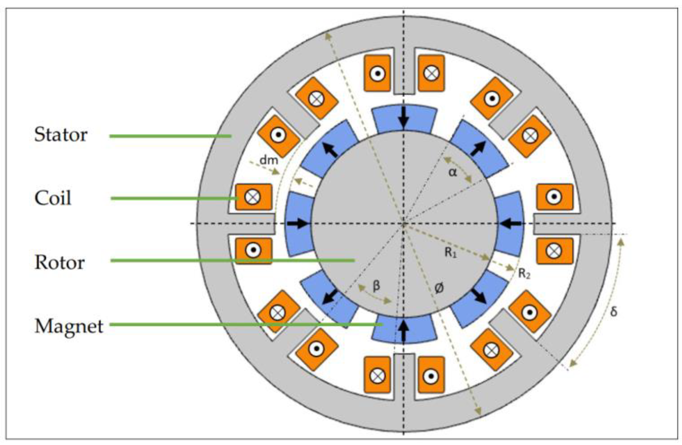
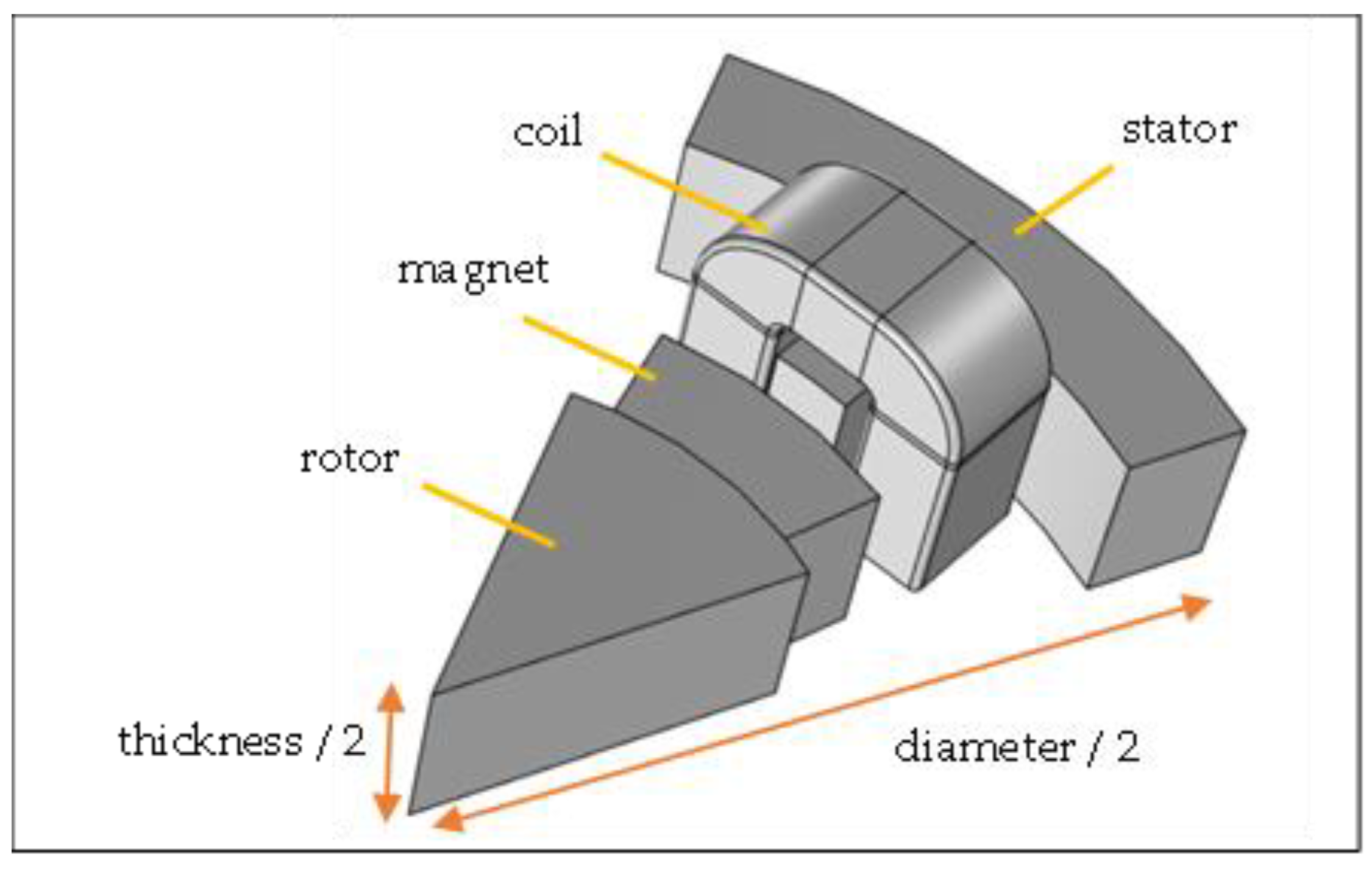
2.1. Geometry of Electromagnetic Generator
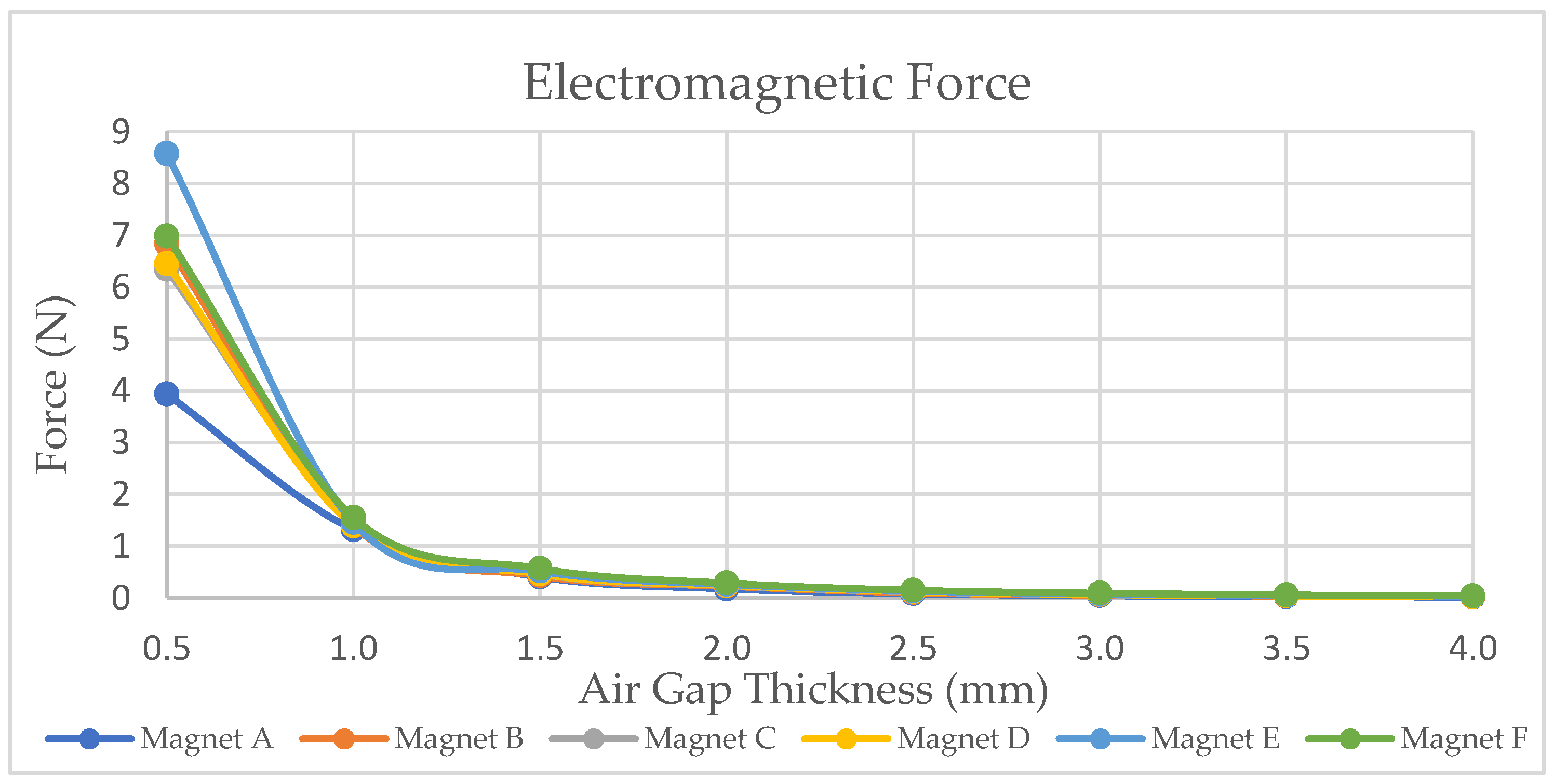
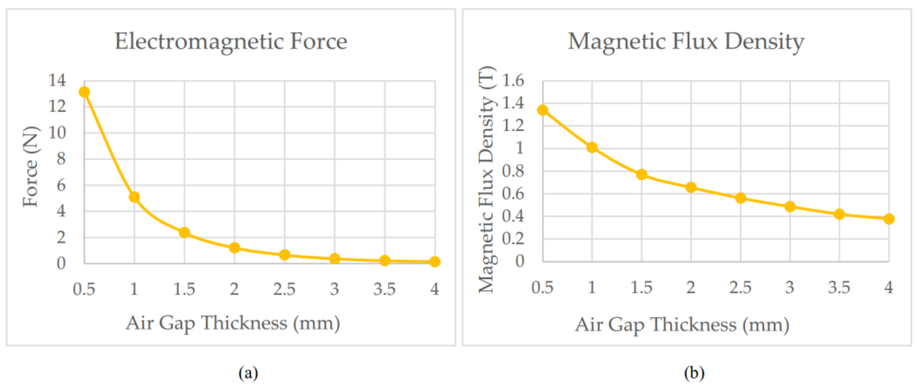
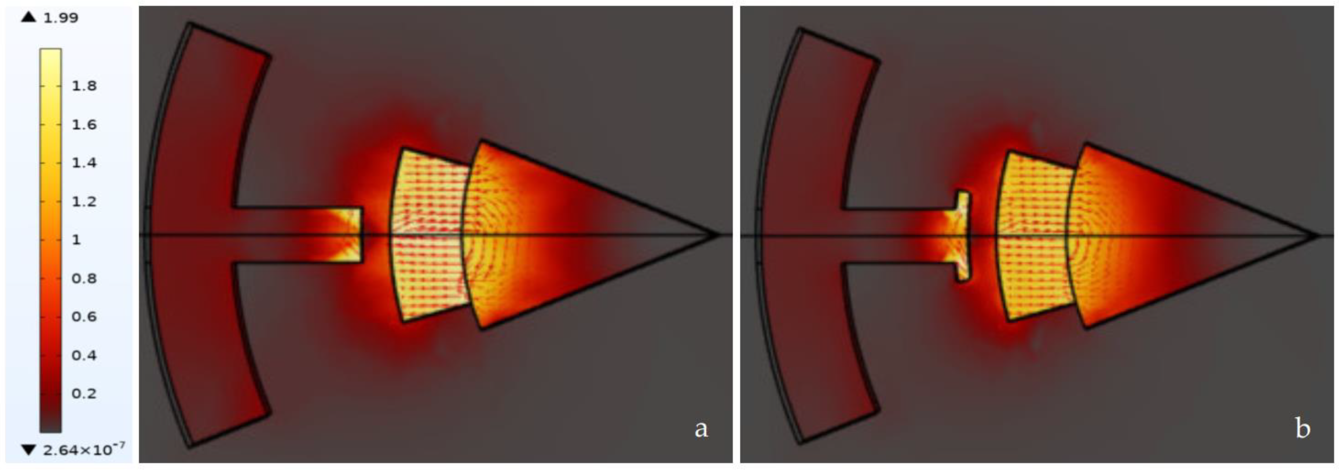
2.2. Air Gap Thickness of the Generator
2.3. Parameters of Electromagnetic Generator
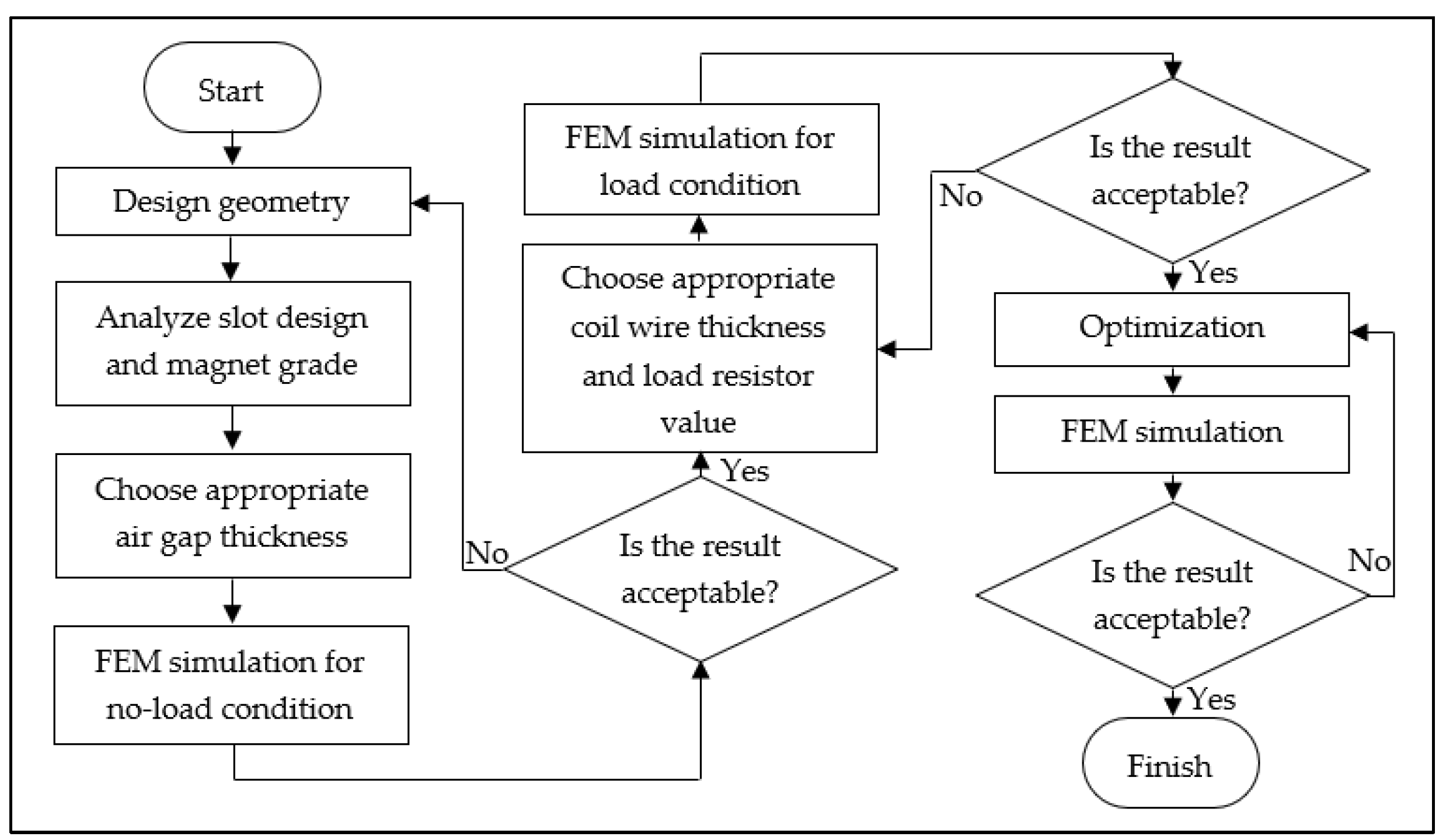
2.4. Simulation
3. Results and Discussion
- As per Jooeun Ahn et al. [30], the average knee angle transition for one complete gait cycle is 122°, which is equivalent to 61° per step.
- As per Werner et al. [31], a male user with a 6-feet 2-inch height would require 1330 steps to reach a 1-km distance if he walked at 1.34 m/s speed.
- By using the values from steps (i) and (ii), the knee angle transition per second can be computed as: knee angle transition = (1.330 steps/meter) × 1.34 m/s × 61°/step = 108.83°/s
- This knee angle transition can be further amplified by using an integrated gear train mechanism. A gear train with a 1:5:5 ratio is occupied for this computation with the assumption of minimal or neglectable friction. The amplified angle is 108.83°/s × 25° = 2720.75°/s.
- The amplified angle of 2720.75°/s is converted to associated revolutions per minute. (2720.75°/s/360°) × 60 s = 453 RPM.
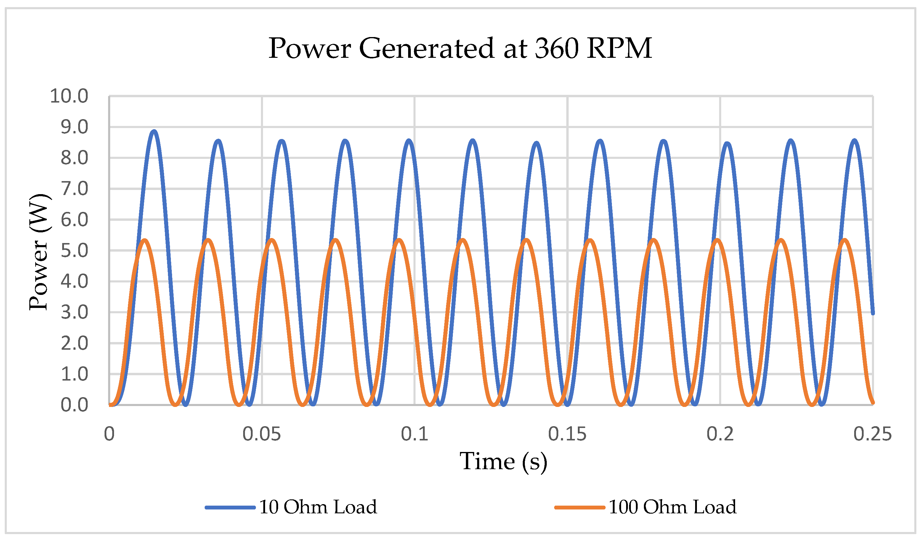
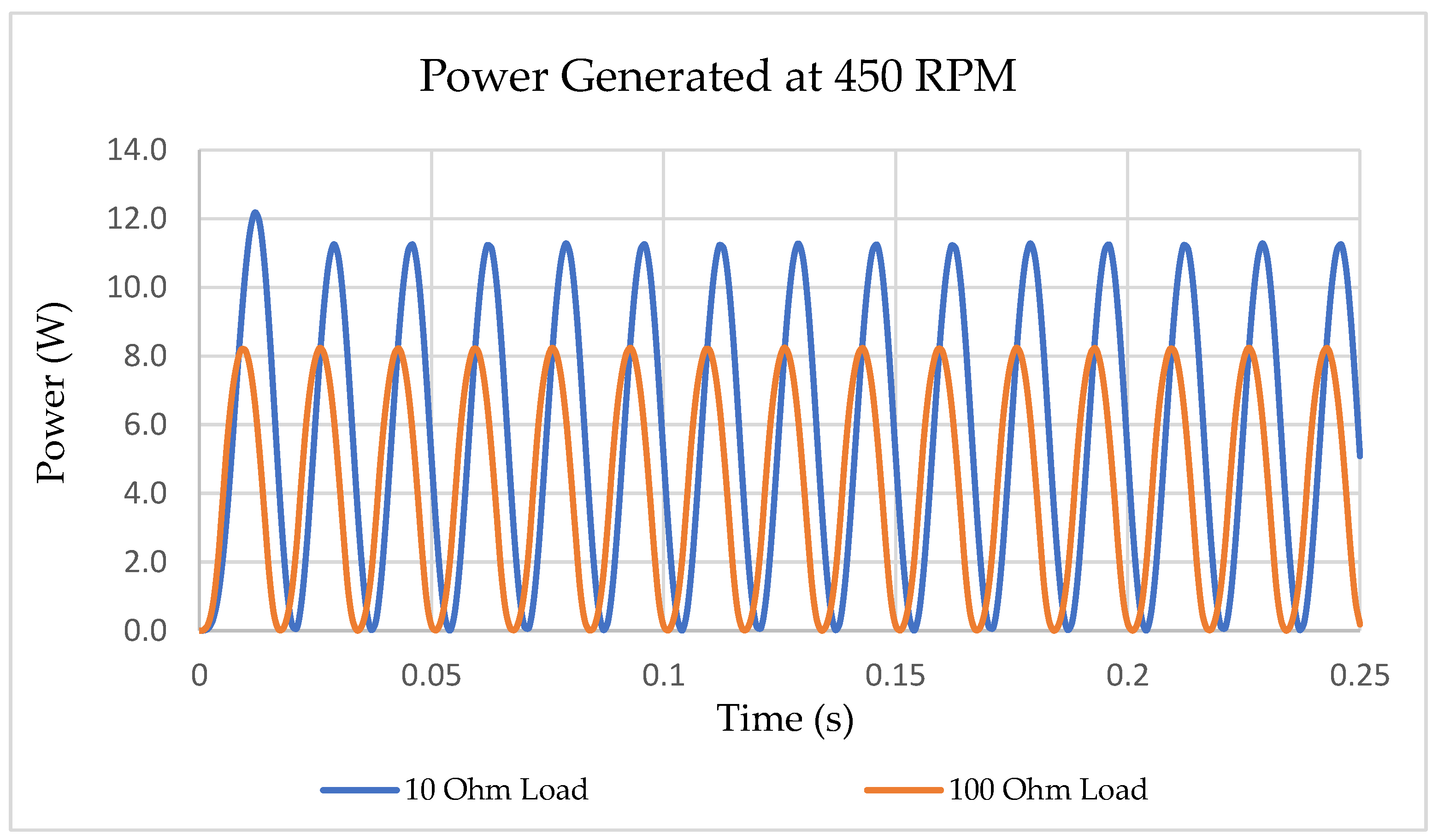
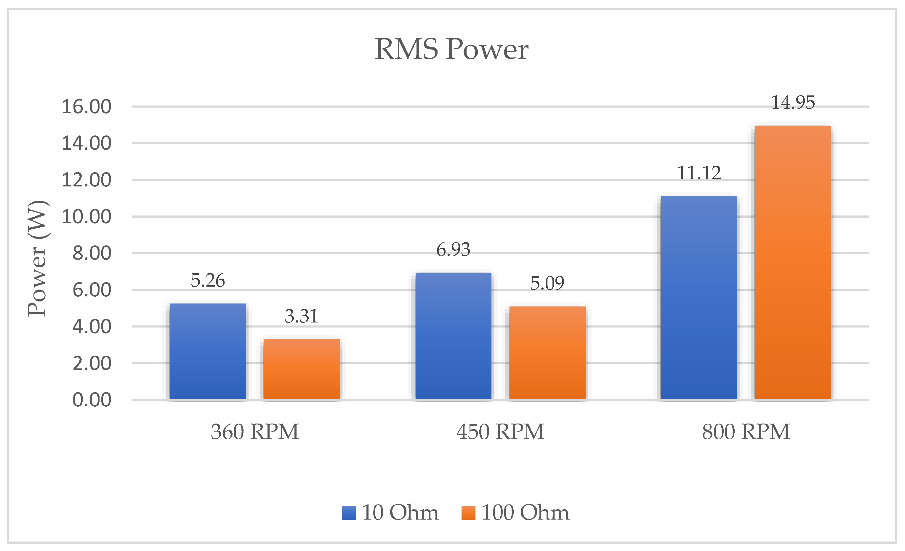
- Based on the simulation results, the generator at a rotation speed of 450 RPM is able to generate RMS power of 6.93 W under a 10-ohm load and 5.09 W under a 100-ohm load. This output is based on single device or per leg.
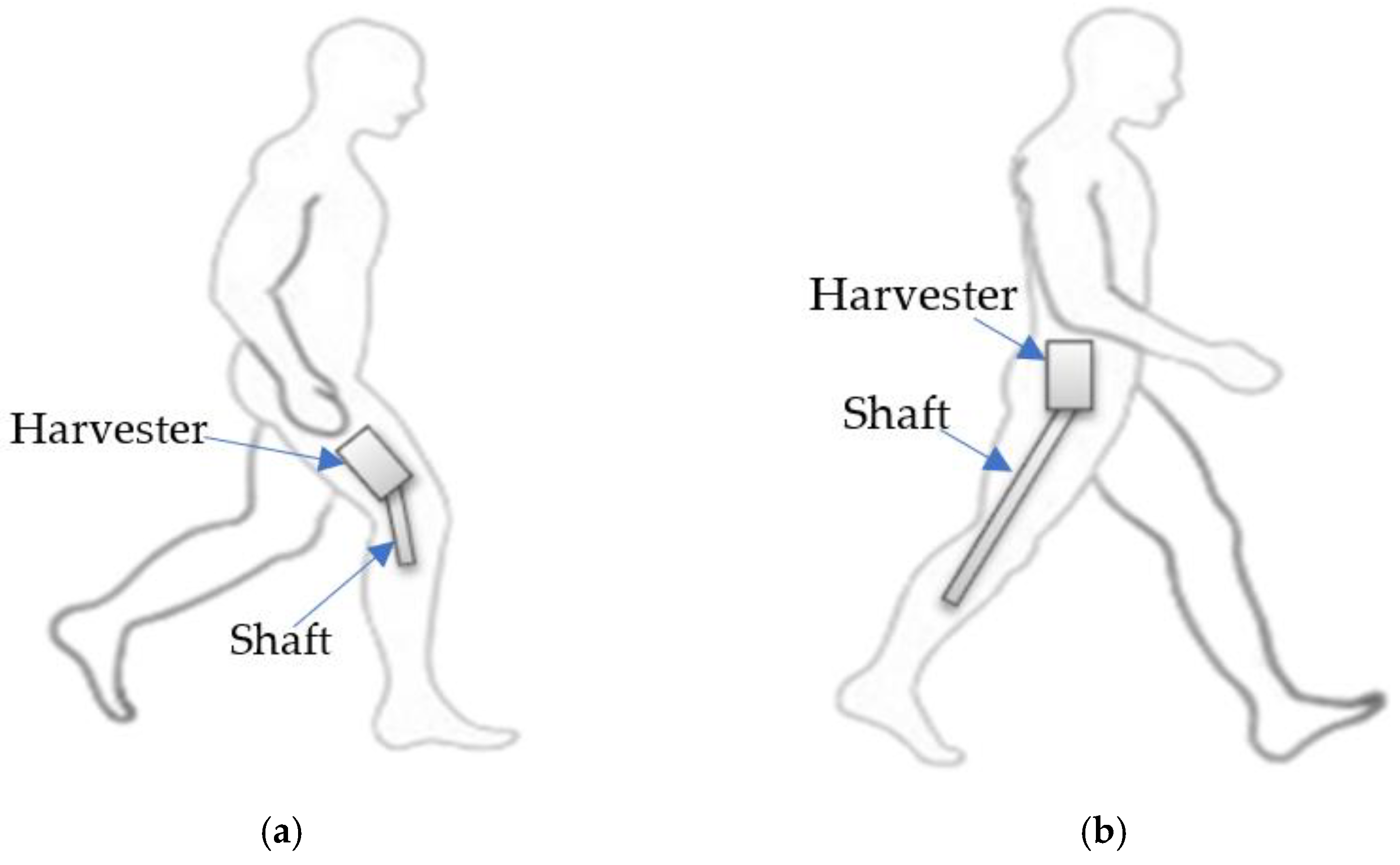
- By using Equation (5), the user needs to apply an input perpendicular force of 0.84 N at the shaft end to actuate the generator and the equivalent energy produced for a 30-min walk will be 6.92 Wh under a 10-ohm load and 5.08 Wh under a 100-ohm load.
- As per Jooeun Ahn et al. [30], the average knee angle transition for one complete gait cycle is 122°, which is equivalent to 61° per step.
- As per Werner et al. [31], a female user with a 5-foot height would require 706 steps to reach a 1-km distance if she runs at 4.47 m/s speed.
- By using the values from steps (i) and (ii), the knee angle transition per second can be computed as knee angle transition = 192.49°/s.
- This knee angle transition can be further amplified by using an integrated gear train mechanism. A gear train with a 1:5:5 ratio is occupied for this computation with the assumption of minimal or neglectable friction. The amplified angle is 4812.25°/s.
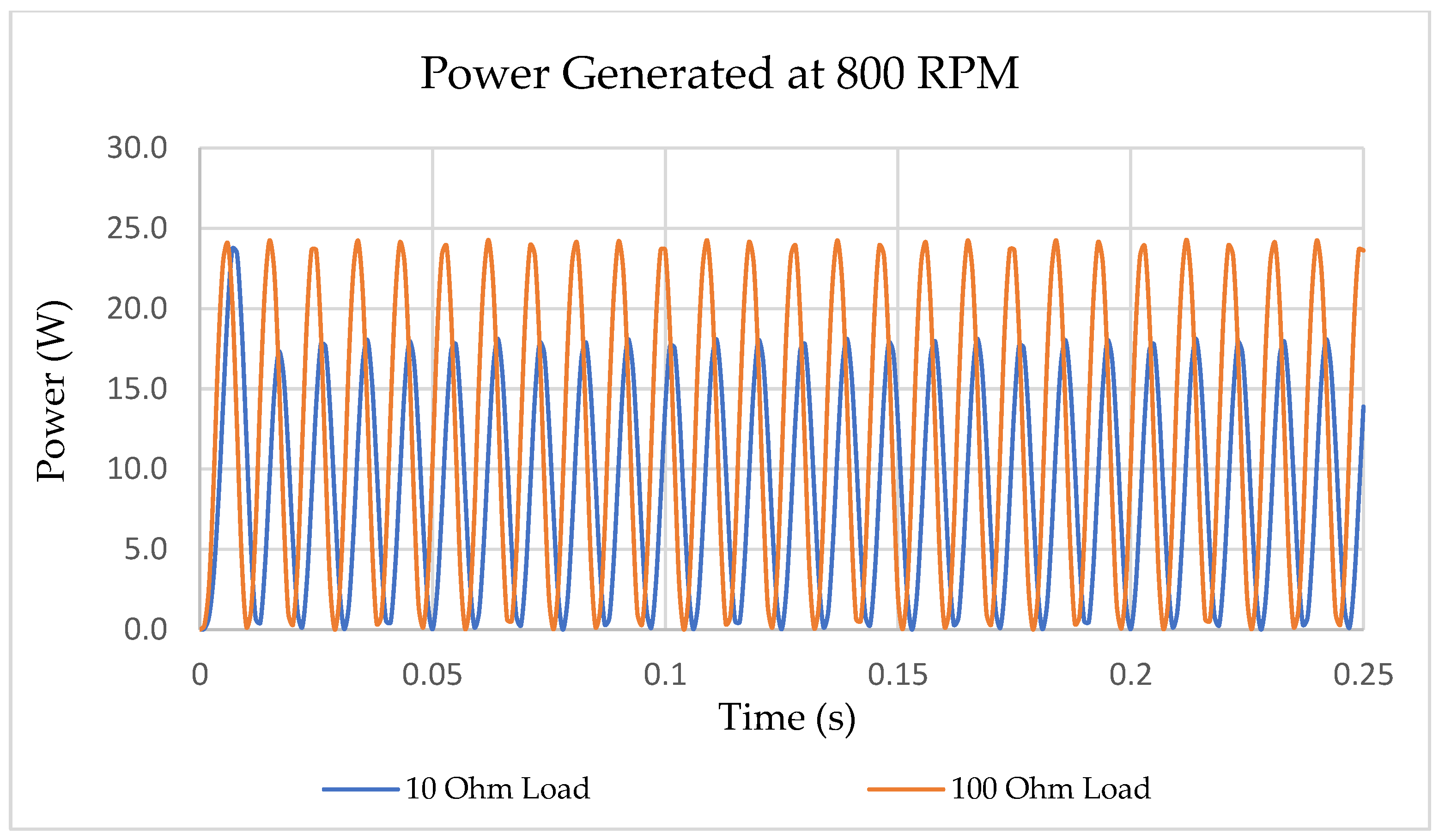
- The associated revolution per minute is 802 RPM.
- Based on the simulation results, the generator at a rotation speed of 800 RPM is able to generate RMS power of 11.2 W under a 10-ohm load and 14.95 W under a 100-ohm load. This output is based on single device or per leg.
- By using Equation (5), the user needs to apply an input perpendicular force of 1.4 N at the shaft end to actuate the generator and the equivalent energy produced for a 30-min walk will be 11.2 Wh under a 10-ohm load and 14.96 Wh under a 100-ohm load.
4. Conclusions
Author Contributions
Funding
Institutional Review Board Statement
Informed Consent Statement
Data Availability Statement
Conflicts of Interest
References
- Erdiwansyah, M.; Husin, H.; Nasaruddin, M.; Muhibbuddin, A. Critical Review of The Integration of Renewable Energy Sources With Various Technologies. Prot. Control. Mod. Power Syst. 2021, 6, 3. [Google Scholar] [CrossRef]
- Zhou, W.; Du, D.; Cui, Q.; Lu, C.; Wang, Y.; He, Q. Recent Research Progress in Piezoelectric Vibration Energy Harvesting Technology. Energies 2022, 15, 947. [Google Scholar] [CrossRef]
- Masood, F.; Nallagownden, P.; Elamvazuthi, I.; Akhter, J.; Alam, M. A New Approach for Design Optimization and Parametric Analysis of Symmetric Compound Parabolic Concentrator for Photovoltaic Applications. Sustainability 2021, 13, 4606. [Google Scholar] [CrossRef]
- Artyukhov, D.; Gorshkov, N.; Vikulova, M.; Kiselev, N.; Zemtsov, A.; Artyukhov, I. Power Supply of Wireless Sensors Based on Energy Conversion of Separated Gas Flows by Thermoelectrochemical Cells. Energies 2022, 15, 1256. [Google Scholar] [CrossRef]
- Truong, K.H.; Nallagownden, P.; Elamvazuthi, I.; Vo, D.N. An Improved Meta-Heuristic Method to Maximize the Penetration of Distributed Generation in Radial Distribution Networks. Neural Comput. Appl. 2020, 32, 10159–10181. [Google Scholar]
- Kumar, M.; Das, B.; Baloch, M.H.; Nallagownden, P.; Elamvazuthi, I.; Ali, A. Optimal Placement and Sizing of Distributed Generators and Distributed-Static Compensator in Radial Distribution System: Distributed Generators and Distributed-Static Compensator. Int. J. Energy Optim. Eng. 2019, 8, 47–66. [Google Scholar] [CrossRef] [Green Version]
- Truong, K.H.; Nallagownden, P.; Elamvazuthi, I.; Vo, D.N. A Quasi-Oppositional-Chaotic Symbiotic Organisms Search Algorithm for Optimal Allocation of DG in Radial Distribution Networks. Appl. Soft Comput. 2020, 88, 106067. [Google Scholar] [CrossRef]
- Dai, Y.; Bai, Y. Performance Improvement for Building Integrated Photovoltaics in Practice: A Review. Energies 2021, 14, 178. [Google Scholar] [CrossRef]
- Konieczna, A.; Roman, K.; Roman, M.; Śliwiński, D.; Roman, M. Energy Efficiency of Maize Production Technology: Evidence from Polish Farms. Energies 2021, 14, 170. [Google Scholar] [CrossRef]
- Calabrese, B.; Velázquez, R.; Del-Valle-Soto, C.; de Fazio, R.; Giannoccaro, N.I.; Visconti, P. Solar-Powered Deep Learning-Based Recognition System of Daily Used Objects and Human Faces for Assistance of the Visually Impaired. Energies 2020, 13, 6104. [Google Scholar] [CrossRef]
- Niu, P.; Chapman, P. Design and Performance of Linear Biomechanical Energy Conversion Devices. In Proceedings of the 37th Power Electronics Specialist Conference, Jeju, Korea, 18–22 June 2006. [Google Scholar]
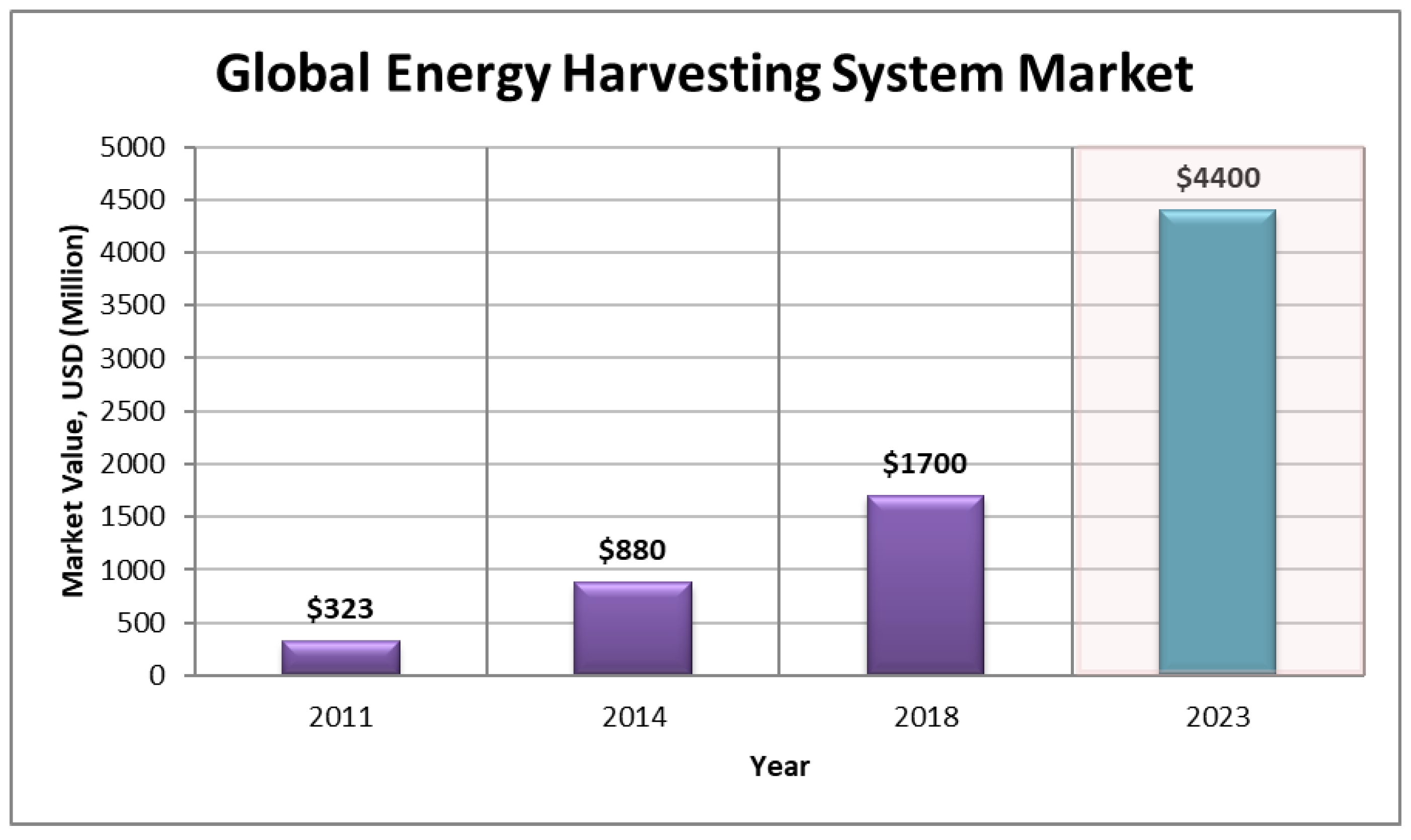
- BCC Research. Available online: https://www.bccresearch.com/market-research/energy-and-resources/energy-harvesting-markets-technology-devices-egy097a.html (accessed on 25 March 2022).
- BCC Research. Available online: https://www.bccresearch.com/market-research/energy-and-resources/energy-harvesting-market-technology-devices-egy097b.html (accessed on 25 March 2022).
- BCC Research. Available online: https://www.bccresearch.com/market-research/energy-and-resources/global-markets-technologies-and-devices-for-energy-harvesting.html (accessed on 25 March 2022).
- Margaria, R. Positive and negative work performances and their efficiencies in human locomotion. Int. Z. Angew. Physiol. 1968, 25, 339–351. [Google Scholar] [CrossRef] [PubMed]
- Paradiso, J.A.; Starner, T. Energy scavenging for mobile and wireless electronics. IEEE Pervasive Comput. 2005, 4, 18. [Google Scholar] [CrossRef]
- Chapuis, A.; Jaquet, E. The History of the Self-Winding Watch; 1770–1931 Rolex Watch Co.: Geneva, Switzerland, 1956. [Google Scholar]
- Rome, L.C. Backpack for Harvesting Electrical Energy during Walking and for Minimizing Shoulder Strain. U.S. Patent 6982497B2, 17 March 2004. [Google Scholar]
- Rome, L.C.; Flynn, L.; Goldman, E.M.; Yoo, T.D. Generating electricity while walking with loads. Science 2005, 309, 1725–1728. [Google Scholar] [CrossRef] [PubMed] [Green Version]
- Donelan, J.M.; Li, Q.; Naing, V.; Hoffer, J.A.; Weber, D.J.; Kuo, A.D. Biomechanical energy harvesting: Generating electricity during walking with minimal user effort. Science 2008, 319, 807–810. [Google Scholar] [CrossRef]
- Winter, D.A. Biomechanical and Motor Control of Human Movement, 3rd ed.; John Wiley and Sons: Hoboken, NJ, USA, 2005. [Google Scholar]
- Feng, Q.; Xu, T.-B. Design, optimization, modeling and testing of a piezoelectric footwear energy harvester. Energy Convers. Manag. 2018, 171, 1352–1364. [Google Scholar]
- Beyaz, M.I. Energy Harvesting from Knee Motion Using Piezoelectric Patch Transducers. Acad. Platf. J. Eng. Sci. 2019, 7–2, 255–260. [Google Scholar] [CrossRef] [Green Version]
- Lei, Y.; Wen, Z.; Chen, L. Simulation and testing of a micro electromagnetic energy harvester for self-powered system. AIP Adv. 2014, 4, 031303. [Google Scholar] [CrossRef]
- Rahman, M.T.; Rana, S.S.; Salauddin, M.; Maharjan, P.; Bhatta, T.; Park, J.Y. Biomechanical Energy-Driven Hybridized Generator as a Universal Portable Power Source for Smart/Wearable Electronics. Adv. Energy Mater. 2020, 10, 1903663. [Google Scholar] [CrossRef]
- Longhan, X. An unpowered flexible lower limb exoskeleton: Walking assisting and energy harvesting. IEEE/ASME Trans. Mechatron. 2019, 24, 2236–2247. [Google Scholar]
- Collier, A.; Schmidt, G. Biomechanical Energy Harvesting Using a Knee Mounted Generator. In Proceedings of the IEEE Systems and Information Engineering Design Conference, Charlottesville, VA, USA, 29 April 2016. [Google Scholar]
- Fan, J.; Xiong, C.-H. A lightweight biomechanical energy harvester with high power density and low metabolic cost. Energy Convers. Manag. 2019, 195, 641–649. [Google Scholar] [CrossRef]
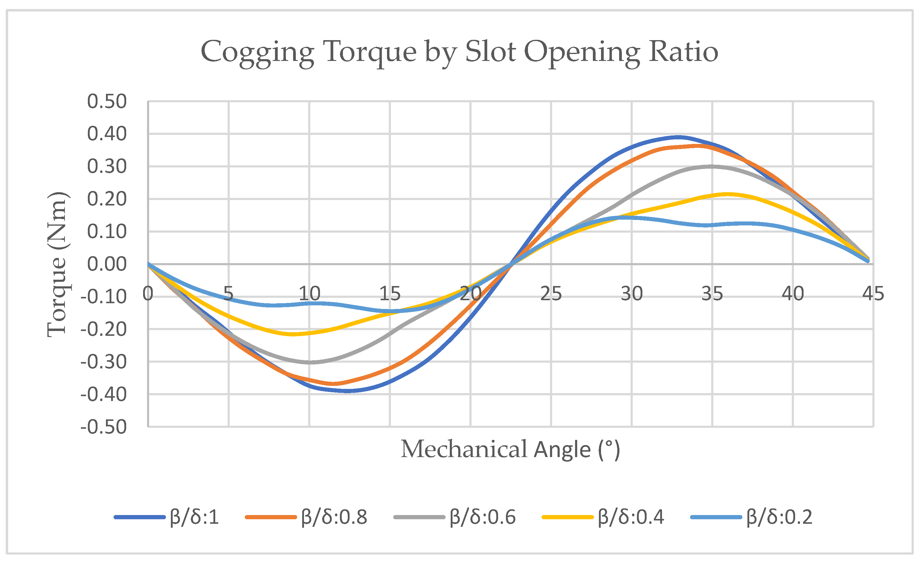
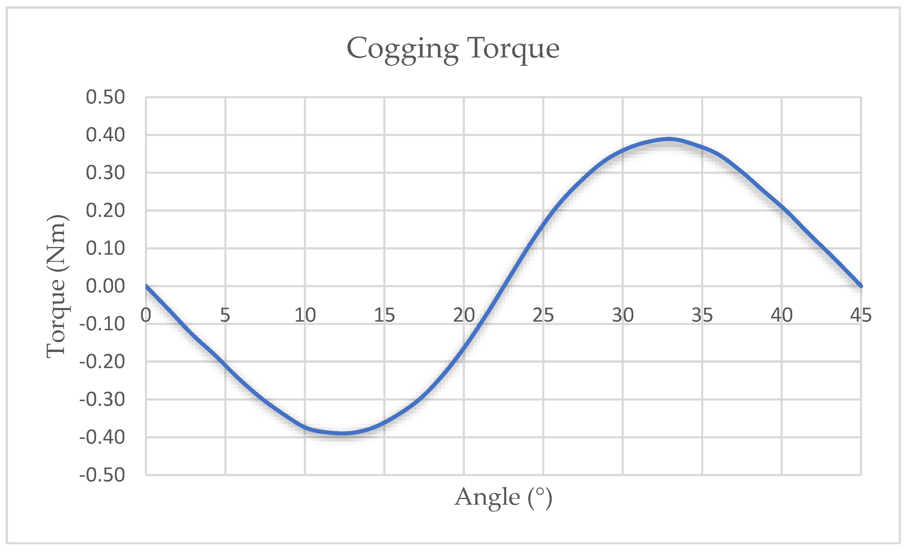
- Zhu, L.; Jiang, S.Z. Optimal slot opening in permanent magnet machines for minimum cogging torque. Przeglad Elektrotechniczny 2011, 87, 3. [Google Scholar]
- Ahn, J.; Hogan, N. Walking is not like reaching: Evidence from periodic mechanical perturbations. PLoS ONE 2012, 7, e31767. [Google Scholar] [CrossRef] [PubMed] [Green Version]
- Werner, W.K.; Bond, L.; Ransdell, L. One-Mile step count at walking and running speeds. ACSM Health Fit. J. 2008, 12, 14–19. [Google Scholar]


| Symbol | Description |
|---|---|
| S | Number of slots |
| P | Number of poles |
| R1 | Inner radius of the rotor |
| R2 | Permanent magnet surface radius |
| Ø | Overall diameter |
| α | Permanent magnet sector angle |
| dm | Air gap thickness |
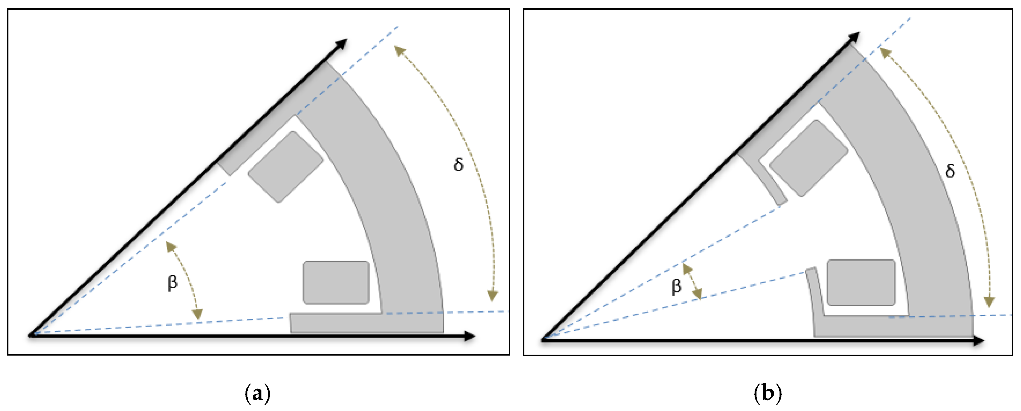
| β | Slot opening angle |
| δ | Slot pitch angle |
| β/δ | Slot opening to slot pitch ratio |
| L | Thickness |
| d | Coil wire diameter |
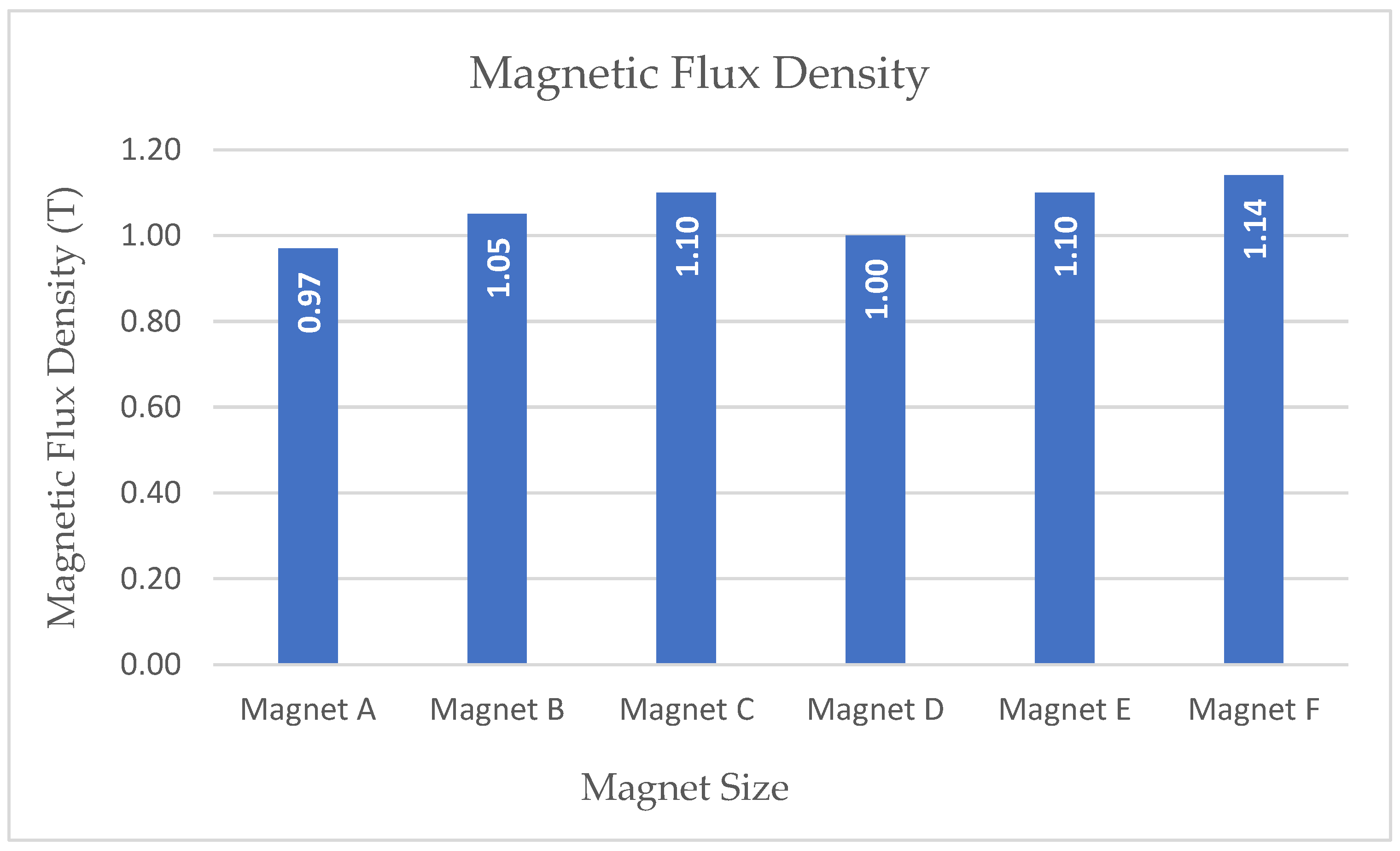
| Magnet Size (mm) (Thickness × Outer Arc Length × Inner Arc Length) | Air Gap Thickness (mm) | |||||||||
|---|---|---|---|---|---|---|---|---|---|---|
| Label | Dimension | 0.5 | 1.0 | 1.5 | 2.0 | 2.5 | 3.0 | 3.5 | 4.0 | |
| Magnet A | 2.0 × 5.38 × 4.39 | 3.931 | 1.314 | 0.402 | 0.173 | 0.081 | 0.042 | 0.025 | 0.015 | Electromagnetic Force (N) |
| Magnet B | 2.5 × 5.62 × 4.39 | 6.831 | 1.387 | 0.426 | 0.225 | 0.099 | 0.054 | 0.035 | 0.020 | |
| Magnet C | 3.0 × 5.86 × 4.39 | 6.339 | 1.452 | 0.460 | 0.236 | 0.116 | 0.061 | 0.041 | 0.026 | |
| Magnet D | 2.0 × 6.14 × 5.03 | 6.449 | 1.390 | 0.462 | 0.241 | 0.122 | 0.065 | 0.040 | 0.025 | |
| Magnet E | 2.5 × 6.42 × 5.03 | 8.580 | 1.454 | 0.516 | 0.261 | 0.133 | 0.078 | 0.050 | 0.035 | |
| Magnet F | 3.0 × 6.70 × 5.03 | 6.985 | 1.550 | 0.568 | 0.285 | 0.147 | 0.091 | 0.056 | 0.038 | |
| Symbol | Description | Value | Unit |
|---|---|---|---|
| S | Number of slots | 8 | |
| P | Number of poles | 8 | |
| R1 | Inner radius of the rotor | 9 | mm |
| R2 | Permanent magnet surface radius | 11.5 | mm |
| Ø | Overall diameter | 20 | mm |
| α | Permanent magnet sector angle | 32 | ° |
| dm | Air gap thickness | 1 | mm |
| β/δ | Slot opening to slot pitch ratio | 1 | |
| L | Thickness | 10 | mm |
| d | Coil wire diameter | AWG 24 | |
| dm | Air gap thickness | 1 | mm |
| RPM | Load | Sector | Coil N-Turn | Stator and Rotor Material | Neodymium Magnet |
|---|---|---|---|---|---|
| 360, 450 and 800 | 10 Ohm and 100 Ohm | 8 | 600 | 35PN230 | N52 |
| Description | Case Study 1 | Case Study 2 |
|---|---|---|
| User height | 6-feet 2-inch | 5-feet |
| Motion speed | 1.34 m/s | 4.47 m/s |
| Shaft length | 250 mm | 150 mm |
| Steps to reach 1 km | 1330 steps | 706 steps |
| Knee angle transition/s | 108.83°/s | 192.49°/s |
| Amplified angle | 2720.75°/s | 4812.25°/s |
| Associated RPM | 450 RPM | 800 RPM |
| RMS power per device with 10-ohm load | 6.93 W | 11.2 W |
| Equivalent energy for 30 min | 6.92 Wh | 11.2 Wh |
| RMS power per device with 100-ohm load | 5.09 W | 14.95 W |
| Equivalent energy for 30 min | 5.08 Wh | 14.96 Wh |
| Force applied by the user | 0.84 N | 1.4 N |
Publisher’s Note: MDPI stays neutral with regard to jurisdictional claims in published maps and institutional affiliations. |
© 2022 by the authors. Licensee MDPI, Basel, Switzerland. This article is an open access article distributed under the terms and conditions of the Creative Commons Attribution (CC BY) license (https://creativecommons.org/licenses/by/4.0/).
Share and Cite
Gurusamy, N.; Elamvazuthi, I.; Yahya, N.; Su, S.; Truong, B.-H. Simulation of Electromagnetic Generator as Biomechanical Energy Harvester. Appl. Sci. 2022, 12, 6197. https://doi.org/10.3390/app12126197
Gurusamy N, Elamvazuthi I, Yahya N, Su S, Truong B-H. Simulation of Electromagnetic Generator as Biomechanical Energy Harvester. Applied Sciences. 2022; 12(12):6197. https://doi.org/10.3390/app12126197
Chicago/Turabian StyleGurusamy, Nedunchelien, Irraivan Elamvazuthi, Norashikin Yahya, Steven Su, and Bao-Huy Truong. 2022. "Simulation of Electromagnetic Generator as Biomechanical Energy Harvester" Applied Sciences 12, no. 12: 6197. https://doi.org/10.3390/app12126197
APA StyleGurusamy, N., Elamvazuthi, I., Yahya, N., Su, S., & Truong, B.-H. (2022). Simulation of Electromagnetic Generator as Biomechanical Energy Harvester. Applied Sciences, 12(12), 6197. https://doi.org/10.3390/app12126197