Article

Comparative Study of Permanent-Magnet Synchronous Machines with Different Rotor Topologies for High-Speed Applications

1
State Key Laboratory of Reliability and Intelligence of Electrical Equipment, Hebei University of Technology, Tianjin 300130, China
2
Key Laboratory of Electromagnetic Field and Electrical Apparatus Reliability of Hebei Province, Hebei University of Technology, Tianjin 300130, China
3
School of Electrical and Information Engineering, University of Sydney, Sydney, NSW 2006, Australia
4
School of Electrical and Data Engineering, University of Technology Sydney, Ultimo, NSW 2007, Australia
*
Author to whom correspondence should be addressed.
Appl. Sci. 2022, 12(9), 4375; https://doi.org/10.3390/app12094375
Submission received: 3 April 2022 / Revised: 22 April 2022 / Accepted: 24 April 2022 / Published: 26 April 2022

Abstract

:
High-speed permanent-magnet synchronous machines (HSPMSMs) are an attractive option for proton-exchange membrane fuel-cell systems. Various HSPMSMs have been developed in the past few years. However, it is difficult to judge which the best candidate is. In this paper, aimed at driving a fuel cell vehicle air compressor, four permanent-magnet machines with different rotor topologies were designed and are compared in terms of electromagnetic, mechanical, rotor-dynamics, and thermal performance. The main topologies of these HSPMSMs are introduced and explained. Then, the electromagnetic and mechanical performance of these HSPMSMs was obtained by using a finite-element method (FEM). To reduce PM demagnetization risk, the temperature increase distributed on the HSPMSMs was also obtained. Lastly, some important conclusions were obtained.

1. Introduction

In recent decades, with energy shortages and environmental degradation becoming the focus of global attention, proton-exchange membrane fuel cell (PEMFC) systems for the automobile industry have become an interesting and promising solution, and the research and development of PEMFC systems have dramatically increased [1]. As the core technology of PEMFC systems, the power density, efficiency, and water balance characteristics of fuel-cell systems can be improved by using air compression technology. However, there is currently no guideline for choosing a compressor and a suitable electrical machine topology.
The main requirements of fuel-cell systems for electrical machines are high rotational speed, compact size, high efficiency, high power density, and low noise. The maximal speed of the targeted machine is almost over 100,000 rpm. Induction machines (IM) [2], permanent-magnet synchronous machines (PMSMs) [3,4], switched-reluctance machines (SRM) [5], and synchronous-reluctance machines (SynRM) [6] exist for air the compressors of fuel cell-systems. Among them, PMSMs are currently the preferred option in the literature when compared with other high-speed (HS) electrical machines because they present high efficiency, high power density, and low acoustic noise. However, few works show how to design an electrical machine regarding electromagnetic, mechanical, rotor-dynamics, and thermal performance; rotor design is a very important issue for HS PMSMs. A major challenge in PMSMs is the trade-off between integrated rotor and high efficiency. Rotor diameter and length are limited by the maximal rotation speed and minimal frequency of bending critical speed, respectively. In order to ensure the high rotational speed of the rotor, maximal rotor diameter and length must be as small as possible. It is also beneficial to reduce windage losses. Nikita et al. [7] proposed a critical design flow of HS PMSMs regarding electromagnetics, mechanical stresses, rotor dynamics, thermal analysis, and manufacturing and assembly. However, the design methodology was inadequate in terms of mechanical and thermal performance, so it could not adapted for other rotor topologies.
Numerous studies were performed to overcome these constraints. To ensure PM rotor integrity, a high-strength sleeve is required for the PM rotor, and Inconel, titanium alloys, stainless steel, and carbon fiber composites (CFCs) can be used for retaining the sleeve [8,9,10,11]. Fang et al. [11] proposed an integrated design for rotor topologies considering electromagnetic and mechanical issues. Inconel and titanium alloys have good thermal conductivity, but their eddy current loss is high, as its conductivity is high if compared with that of CFC. Though CFC can achieve very high strength and low eddy current loss, its thermal conductivity is very low, which leads to the PM rotor facing the risk of overheating and demagnetization. Therefore, to achieve overall good performance, the above aspects need to be considered. In the design of high-power machines, Zhang et al. [9] developed a hybrid sleeve composed of a titanium alloy and carbon fiber. Moreover, Liu et al. [12] proposed an HS sleeve-free PM rotor using amorphous magnetic materials; thus, sleeves were avoided. It can trade off core losses and mechanical stress, but rotor heat was high.
To resolve this challenge, reducing losses and improving the cooling method are both effective. In order to achieve accurate thermal distribution, HSPMSM losses need to be accurately calculated [13]. The rotor eddy current loss of HSPMSMs is induced by space harmonics caused by the slotting effect and time harmonics, caused by the winding current [14]. In [15], a new method was proposed to predict rotor losses considering the slotting effect and its interaction with stator winding, and it could be extended for predicting whole rotor loss, including retaining sleeve and shaft. However, it is difficult to obtain actual power losses when an inverter exists. To solve this problem, Chiodetto et al. proposed a field-circuit coupling finite-element method established by considering the slotting effect and its interaction with stator winding generated by the magnetic field harmonic [16].
In order to increase power density, an efficient cooling method is necessary to break the thermal constraint. Cooling methods including liquid, forced-air, and spray-oil cooling were studied and compared [17]. In order to closely cool a rotor, a forced air–water cooling structure with air channels set in stator slots was proposed to further cool the rotor [18]. In recent years, rotor configurations with different sleeves were studied. A rotor with different PM configurations has not been studied, especially considering multiphysical field analysis.
In this paper, quantitative comparative analysis was conducted for a 19 kW, 160 krpm HSPMSM with four different rotor configurations. This paper is organized as follows. In Section 2, the specification of HSPMSMs with different rotor configurations is presented. General design concepts are described in terms of construction and fabrication. In Section 3, multidisciplinary analysis and optimization based on the finite-element method (FEM) are performed. The torque capability, efficiency, and mechanical strength of HSPMSM with different rotors are investigated. Rotor nature frequency ensures safe operation. On the basis of FEM, the nature frequency of permanent-magnet rotors is predicted. Section 4 shows the power loss of these machines. Furthermore, thermal analysis is performed in Section 5. Ultimately, the weight average method was adopted to compare and discuss the final performance of these four machines in Section 6, and conclusions are then summarized.

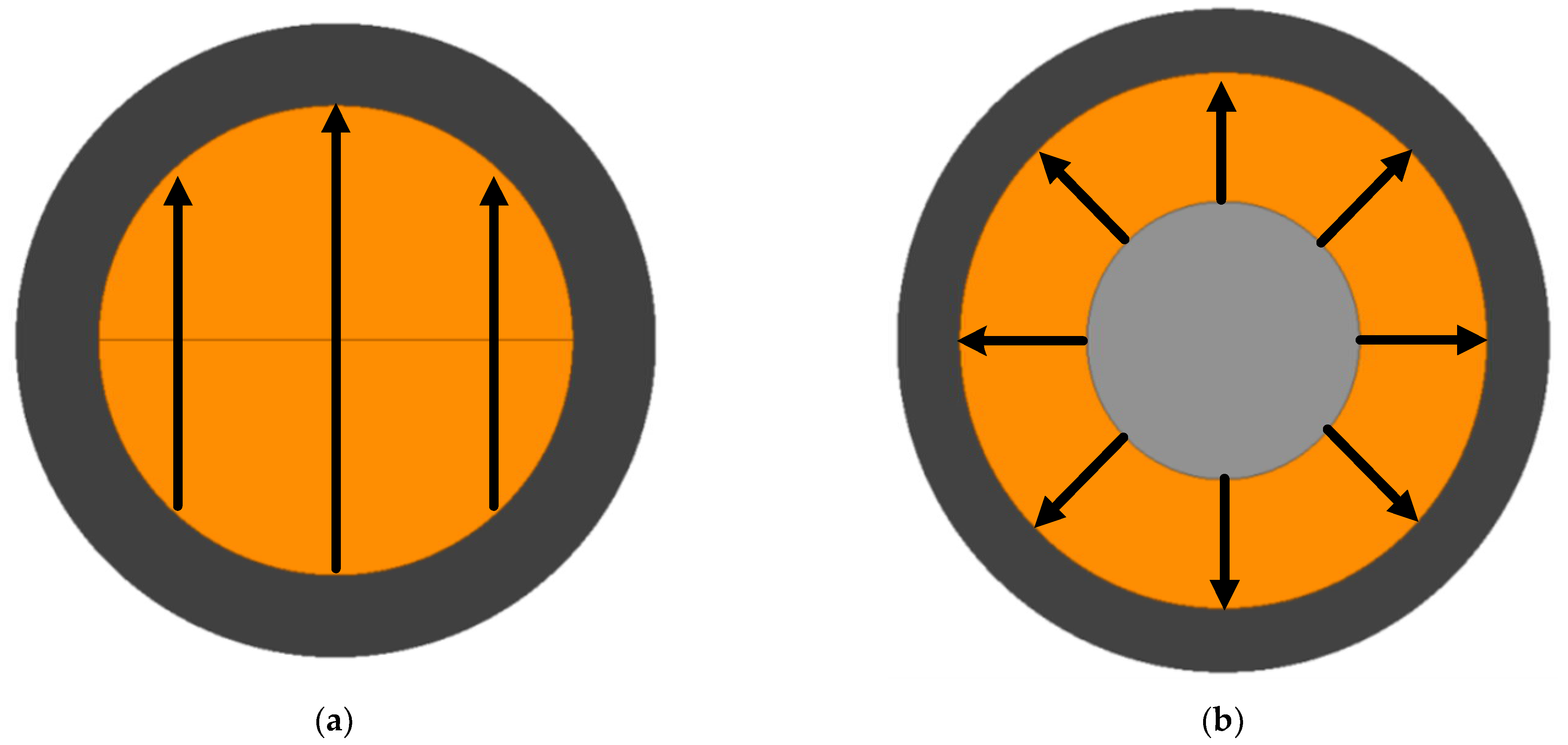
2. General HSPMSM Structure

In this section, the general concept of HSPMSM, including specifications and topology, is presented. Four 19 kW 160 krpm HSPMSMs were designed for fuel-cell electric-vehicle air compressors; each had 6 stator slots and 2 rotor poles, which resulted in the number of slots per pole per phase being 1 (q = 1) in a three-phase machine. The winding factor of concentrated tooth-coil winding is only half of that of full-pitch winding. The fundamental winding factor of concentrated tooth-coil winding is lower due to its narrow winding step. However, the number of winding turns is so low that halving them does not seriously harm machine performance in HS applications. Iron and rotor losses increase with concentrated tooth-coil windings due to the higher air-gap harmonic content compared to that in distributed windings. The amount of copper can be nearly the same in concentrated tooth-coil and full-pitch windings, as full-pitch winding ends are longer than compact-end windings in the case of tooth-coil windings. To reduce end winding length and improve structure robustness, concentrated tooth-coil windings were adopted for these machines, as shown in Figure 1e. Shorter axial length leads to shorter rotor length, which improves the boundaries of the rotor dynamics with respect to critical speed. The targeted machines’ specifications and used material are shown in Table 1. The drawbacks of NdFeB are its bad thermal tolerance and tension weakness. As the ambient environment of the designed machines was not hostile, the maximal operating temperature was below 200 °C; thus, NdFeB was acceptable [14].
Four different rotors were designed and are shown in Figure 1 with the same stator configuration. For achieving the performance requirements of the air compressor, the main parameters and used materials of these HSPMSMs are shown in Table 1. In order to balance maximal efficiency and mechanic robustness, a titanium alloy (Ti-6Al-4V) and CFC were utilized to protect the PM in M1 and M2, respectively. Although the bulk conductivity and flexural modulus of the titanium alloy were higher, they come with greater eddy current losses. As core stator loss is very high under high-speed operation, the high-silicon sheet of 10JNEX900 was utilized to build the stator core.
In manufacturing, M1 offers the advantage of high dimensional accuracy, but its assembly process, including that of a PM rotor with its shaft, is complicated and very difficult. Figure 1b shows that the M2 rotor is quite similar to a conventional surface-mounted PM rotor; PM is directly glued on the shaft and is externally protected by CFC. As the strength of shaft is high, the flexural modulus of rotor is high. Figure 1c,d show the interior PM rotors of M3 and M4, which have good flux weakening ability and are sleeve-free. Their sleeve could be removed by utilizing high-strength rotor materials; thus, high-silicon sheets were selected for the rotor core. Moreover, to reduce eddy current loss, the PM needed to be segmented.

3. Mechanical–Electromagnetic Performance Analysis

The rotor structure determines the centrifugal force during HS operation; electromagnetic and mechanical performance needs to be considered in the preliminary design stage. In order to reduce eddy current loss, PMs are divided into pieces, while rotor rigidity is decreased. Therefore, the thickness of PM and sleeve needs to be optimized with a smaller rotor diameter and good electromagnetic performance. The electromagnetic and mechanical performance of these HSPMSMs is analyzed and compared in this section. Table 2 shows the rotor design parameters and material properties of these HSPMSMs.

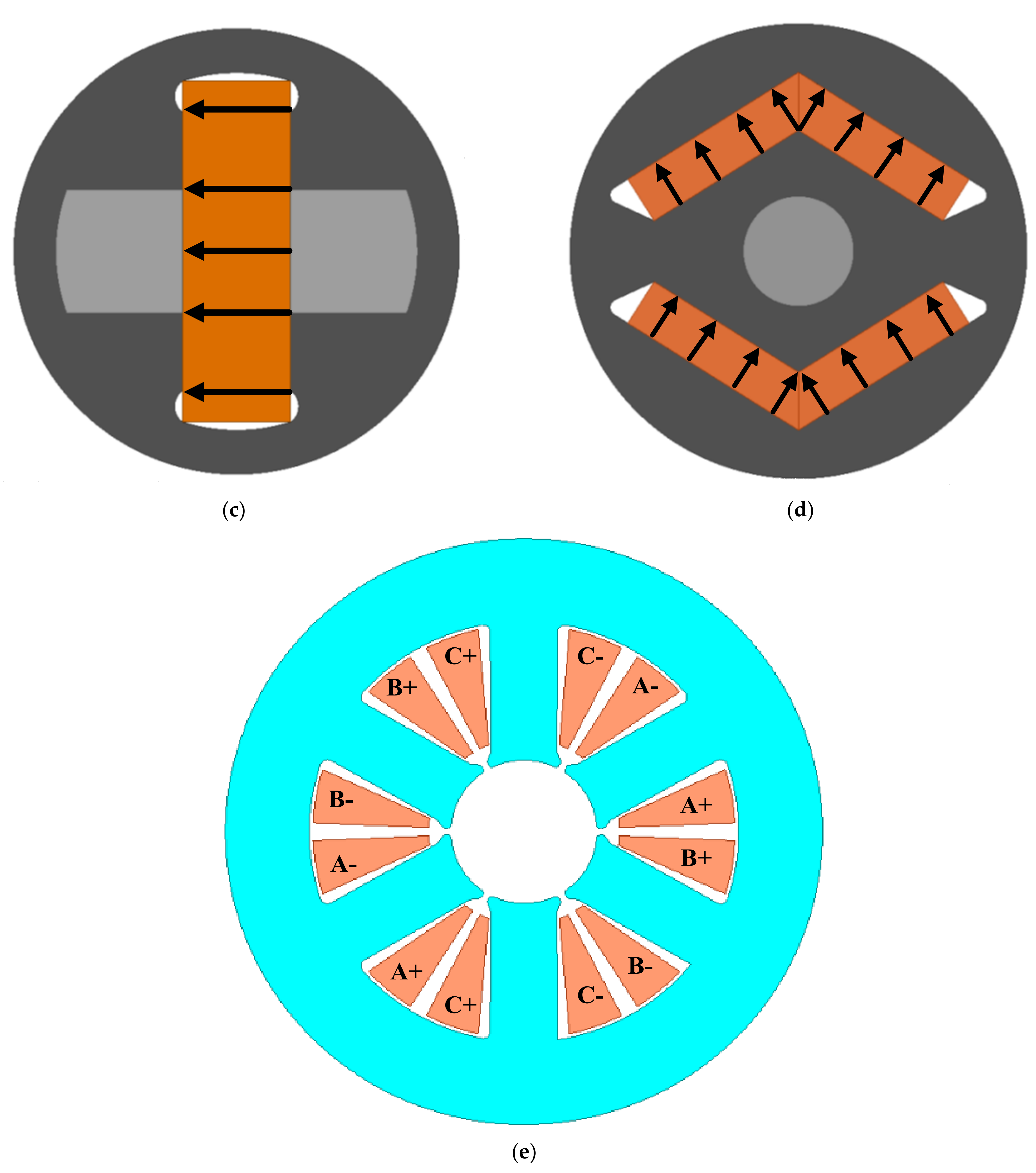
3.1. Electromagnetic Performance Comparison

After design optimization, the electromagnetic performance of HSPMSMs with different rotor configurations was analyzed and investigated on no-load and rated-load states by using Ansys Maxwell. Figure 2a shows the no-load back-EMF of these machines at the rated speed. The amplitude of the back-EMF of M3 was maximal, but it also had great 3rd and 5th harmonics. The waveform of M1 was close to that of sinusoidal waves, and its harmonics were the least. Figure 2b shows the Fourier analysis of the back-EMF of these HSPMSMs. Higher-order harmonics result in higher loss. The total harmonic distortion of M1 was much lower than that of other HSPMSMs; thus, loss in M1 was low. In other HSPMSMs, though the 3rd harmonics of M3 were the highest, M4 had highest total harmonic distortion. Figure 2c shows the no-load PM flux linkage for these HSPMSMs at the rated speed.
The output torque of the PMSM can be obtained by:
T e m = P o u t ω r = η m 2 p φ m k s f N s m A s J m
where η is the efficiency of the machine, m is the number of phases, p is the number of rotor poles, φm is the flux linkage of winding per turn, ksf is the slot fill factor, Ns is number of stator slots, As is slot area, and Jm is current density. On the basis of the equation above, the electromagnetic torque of the PMSMs is proportional to the product of flux linkage and winding current.
Output torque is another key performance aspect for designing an HSPMSM. As these four HSPMSMs were designed with the same output power level, their torque ripple and PM usage are other key factors. Figure 3 shows the torque waveform, torque ripple, and PM usage comparison of these HSPMSMs. The torque ripple of M1 was 0.88%, which was the lowest compared with that of the other HSPMSMs, and the torque ripple of M3 was 10.01%, which was the highest. Regarding PM usage, that of M4 was 1150.1 Nm/cm3, which was the highest. M2, on the other hand, had the lowest (854.2 Nm/cm3). After further optimization, the harmonics and torque ripple could be further decreased, especially for M4. In terms of electromagnetic performance, M1 was easy to manufacture, and M4 is promising for further development.

3.2. Mechanical and Rotor Dynamics Performance Analysis

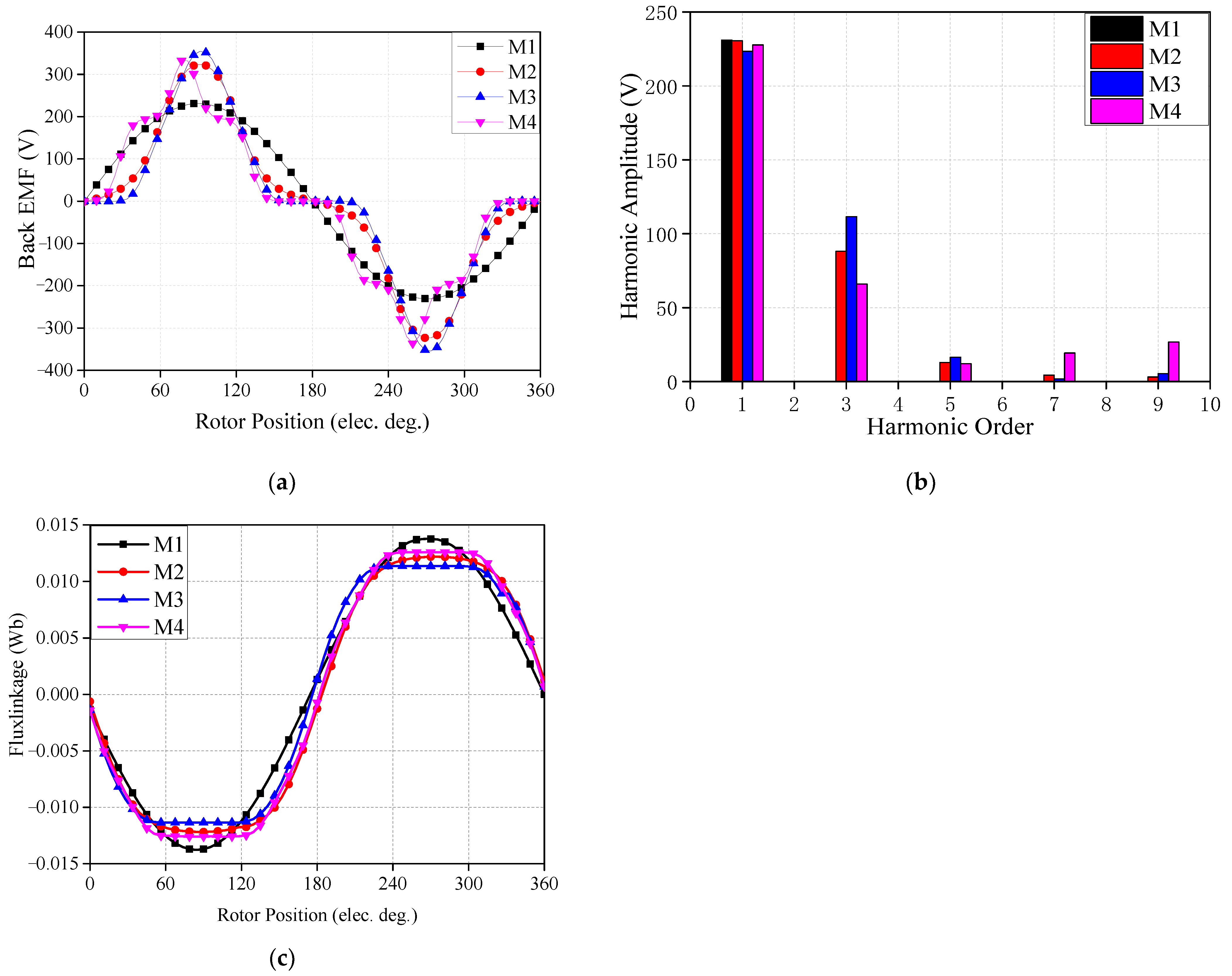
3.2.1. Mechanical Stress Analysis

After electromagnetic design, mechanical design is examined. However, this process is not suitable for designing a HS machine due to the existence of a large centrifugal force. The PM contributes much less to rotor rigidity than the shaft does. Therefore, in order to obtain a more robust rotor, the shaft diameter needs to be maximized when the rotor outer diameter is fixed. Furthermore, a sleeve is employed to protect the PM from interference or shrink fit. The mechanical design of HSPMSMs was investigated, focusing on obtaining optimal sleeve design. In this section, mechanical performance is optimized and compared in terms of stress and dynamics under the same output power. In order to ensure that the rotor could run in an HS state, the following mechanical constraints need to be considered:
(1)
maximal stresses in the sleeve cannot exceed their permissible safety stress;
(2)
contact force between PM and sleeve is high enough to meet torque transfer;
(3)
rate rotor speed is below the first critical speed, and its difference needs to be more than 15% at least.
Because sleeve stress changes with rotation speed and working temperature, the worst condition, with the rotor at 160 kpm and 120 °C, is considered in this section. In the integrated rotor, mechanical stress in each part of the rotor needs to be lower than the permitted stress value. Mechanical stress is calculated by using 3D FEM. The material properties of the retained sleeve were obtained from the material suppliers and are shown in Table 2. As M1 was a cylindrical PM structure, a Ti6Al4V was used as the sleeve to enhance rotor rigidity. The permitted stress of CFC and Ti6Al4V is 1000 and 1300 Mpa along the tangential direction, which was adopted in M1 and M2, respectively. The permitted stress of silicon sheet 10JNEX900 is only 700 Mpa, which is used as the M3 and M4. The calculated mechanical stress distribution and total deformation on the sleeve at the rated operation conditions are shown in Figure 4 and Figure 5. All rotor parts could meet the material requirements, and M1 presented the lowest stress due to its smaller rotor diameter and solid cylindrical structure. For M3 and M4, the maximal stress of the sleeve occurred at the flux bridge, while it was less than 90% of the permitted stress of the adopted material, as shown in Figure 4c,d. The total deformation of M3 was the highest, but this kind of deformation was still within the permitted elastic deformation, as shown in Figure 5c. When the maximal stress was within the permitted range, the sleeve-free M3 and M4 had more advantages, while M1 and M2 had higher stress limitations due to their use of a sleeve.

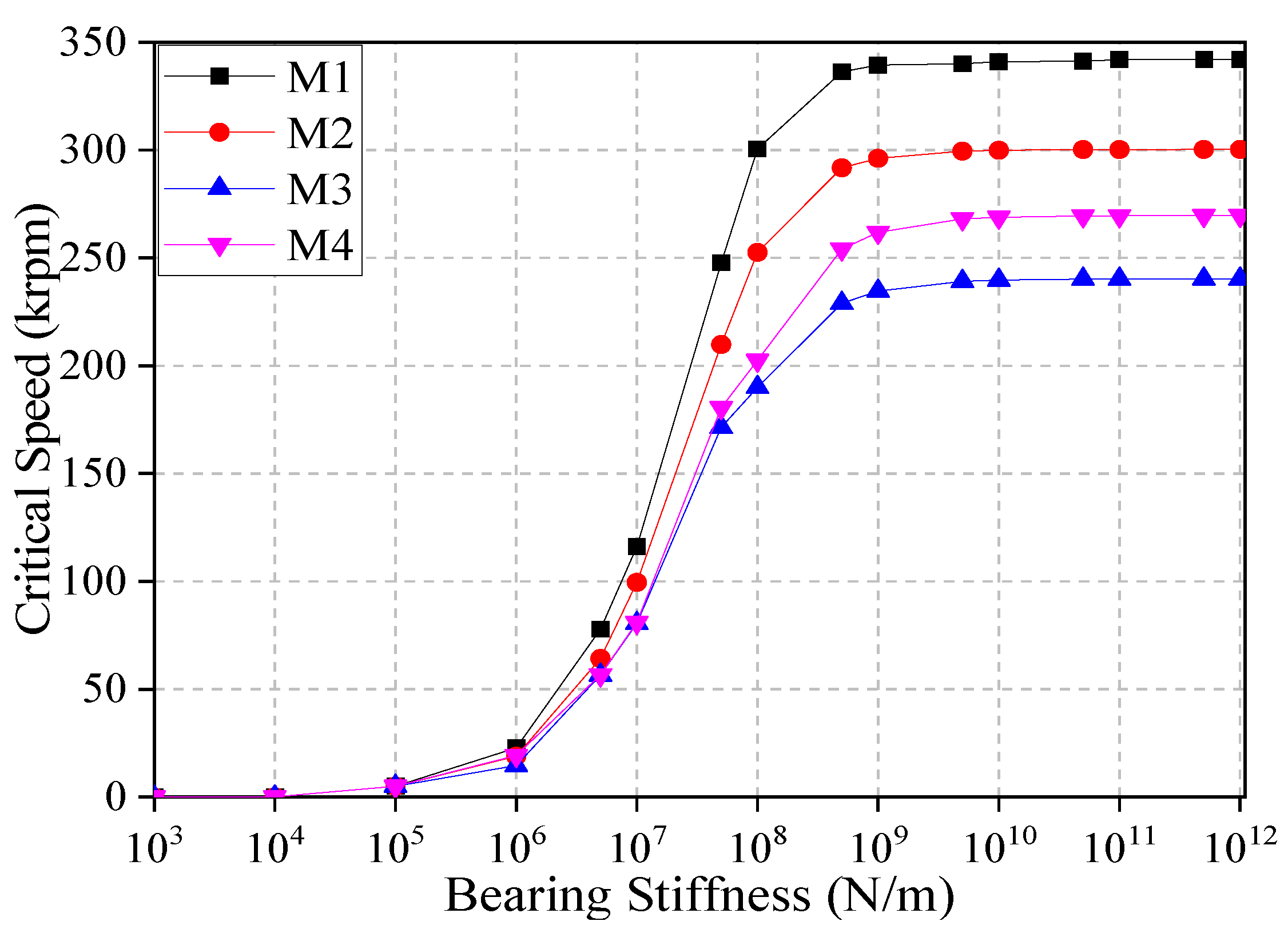
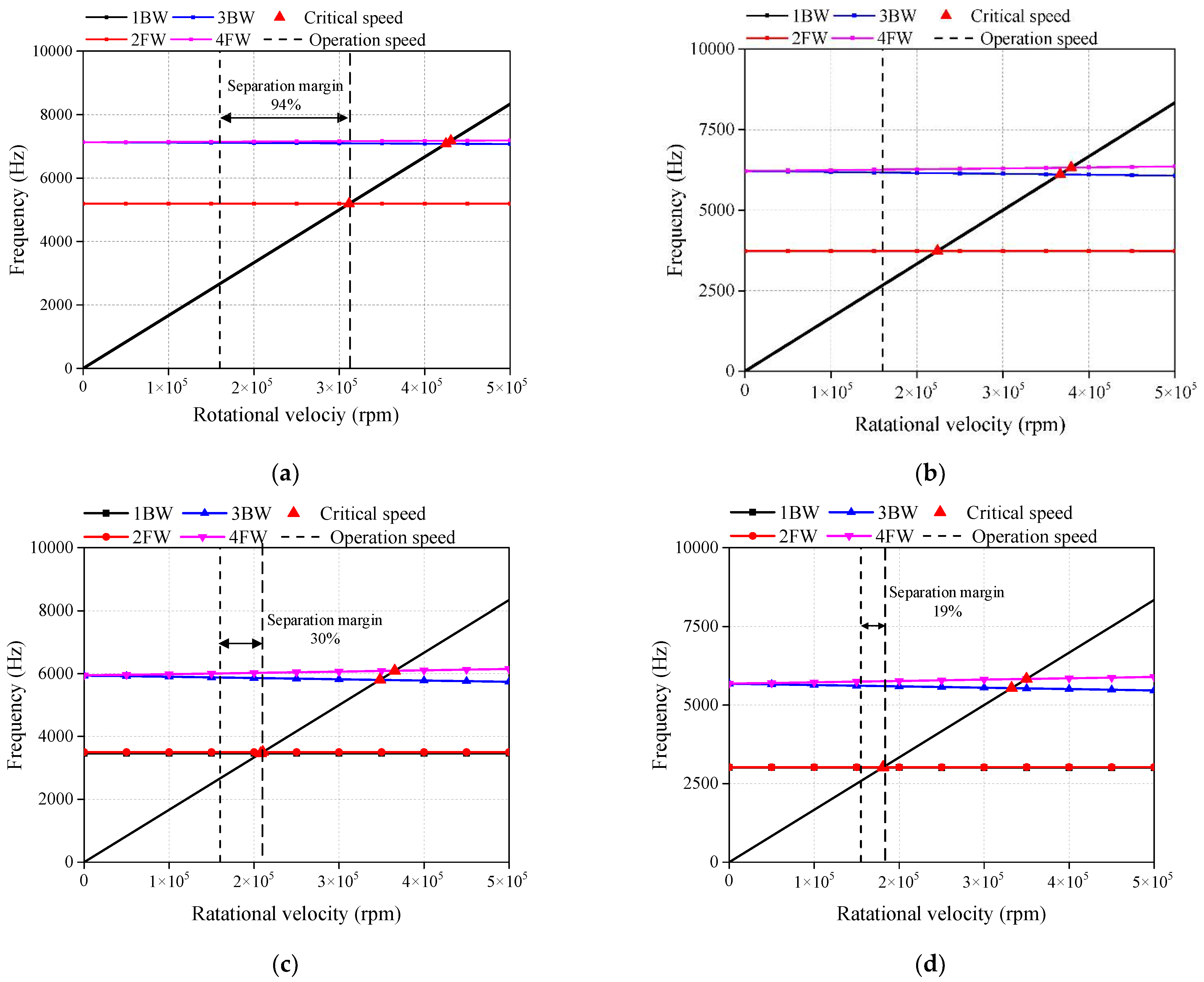
3.2.2. Rotor Dynamic Performance

For HSPMSM design, rotor dynamic performance analysis is very important; when operation speed reaches the critical speed, the rotor wound resonates at its nature frequency and is then damaged. Nature speed is determined by axial length, rotor diameter, and its bearing stiffness; thus, changing bearing stiffness can change the rotor’s critical speed. In modal analysis, 3D FEM rotor dynamic analysis is performed, and nature frequency and mode shape are calculated. Figure 6 shows the relationship between critical speed and bearing stiffness with the same stack length. The separation margin between bending forward whirling critical speed and operation speed should be as large as possible. When bearing stiffness is less than 1 × 10⁶ or exceeds 1 × 10⁹ N/m, it does not impact the first critical speed much. Critical speed is determined by bearing stiffness when bearing stiffness is between 1 × 10⁶ and 1 × 10⁹ N/m. In this paper, the airfoil bearing was selected due to its advantages in high-temperature and HS conditions. Generally, the commercial gas dynamic bearings can achieve rotational speed of up to 600 krpm. The bearing stiffness of airfoil bearing is 5 × 10⁷ N/m in this paper. All HSPMSMs could safely operate at 160 krpm. Figure 7 shows the Campbell diagram of HSPMSMs with different rotors. The first critical speed and separated margin of M1 were 311.3 krpm and 90%, respectively, which was the best dynamics performance. M3 and M4 presented worse dynamics performance than that of M1 and M2 due to their sleeveless rotor topology. However, all these rotors could safely operate at the rated speed.

4. Losses Analysis

For HSPMSMs, losses are mainly core, copper, eddy-current, and windage losses. Because HSPMSM volume is limited, loss needs to be accurately calculated to facilitate cooling system design and ensure efficient machine operation.

4.1. Core Loss

Core loss accounts for a substantial proportion of total power loss and is much higher than other losses in HSPMSMs. The core loss of soft magnetic material in electrical machines is generally estimated according to loss separation theory, including hysteresis loss Ph, eddy current loss Pe and anomalous loss Pa [19,20],
P c = P h + P e + P a = k h f B m 2 + k e f 2 B m 2 + k a f 1.5 B m 1.5 ,
where kh, ke, and ka are the coefficients of hysteresis loss, eddy current loss, and anomalous loss, respectively; f is operating frequency; and Bm is flux density magnitude. In this paper, a high-silicon sheet was selected for developing the HSPMSM. On the basis of the experimental data, the loss coefficient could be obtained by the fitting method, and the obtained coefficients were kh = 133.47, ke = 0.014, and ka = 1.26.

4.2. Copper Loss

AC copper loss considering skin and proximity effects can be expressed by [21]:
P a c = k s p I 2 R ,
where ksp is the coefficient accounting for skin and proximity effects, I is the effective value of the winding current, and R is the winding DC resistance.
For form winding, skin and proximity effects significantly affect copper loss at high frequencies, as winding resistance increases as working frequency increases due to the skin and proximity effects [22]. In this paper, tooth-wound winding was used due to its winding end being short. For a given current, the skin effect is affected by winding size. Skin depth δ can be calculated by
δ = 1 / π σ c f μ 0 μ r ,
where σc is the electrical conductivity of the conductor, μ0 is the permeability of the internal space, and μr is the relative permeability of the conductor. At a frequency of 2600 Hz, the calculated skin depth was 4.04 mm based on Equation (3).
Generally, when the total cross-sectional area of stator slot and slot fill factor are kept the same, the skin effect is higher when the single wire is thicker. Figure 8 shows ksp versus the ratio of wire thickness to skin depth at different frequencies. When the wire thickness increased to 0.8 times of skin depth, ksp quickly increased. Therefore, a wire of 5 mm width and 1.2 mm thickness was adopted for this research, and ksp was set to be 3.55 to calculate copper loss.

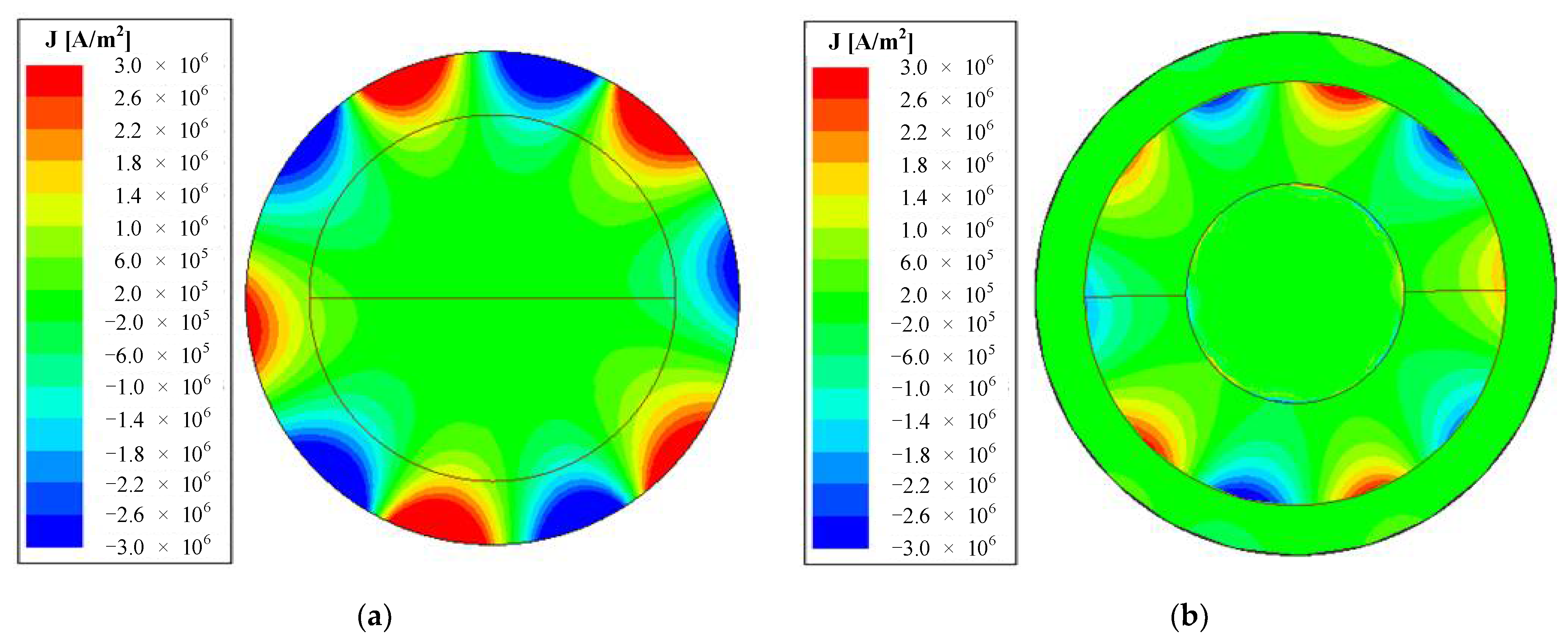
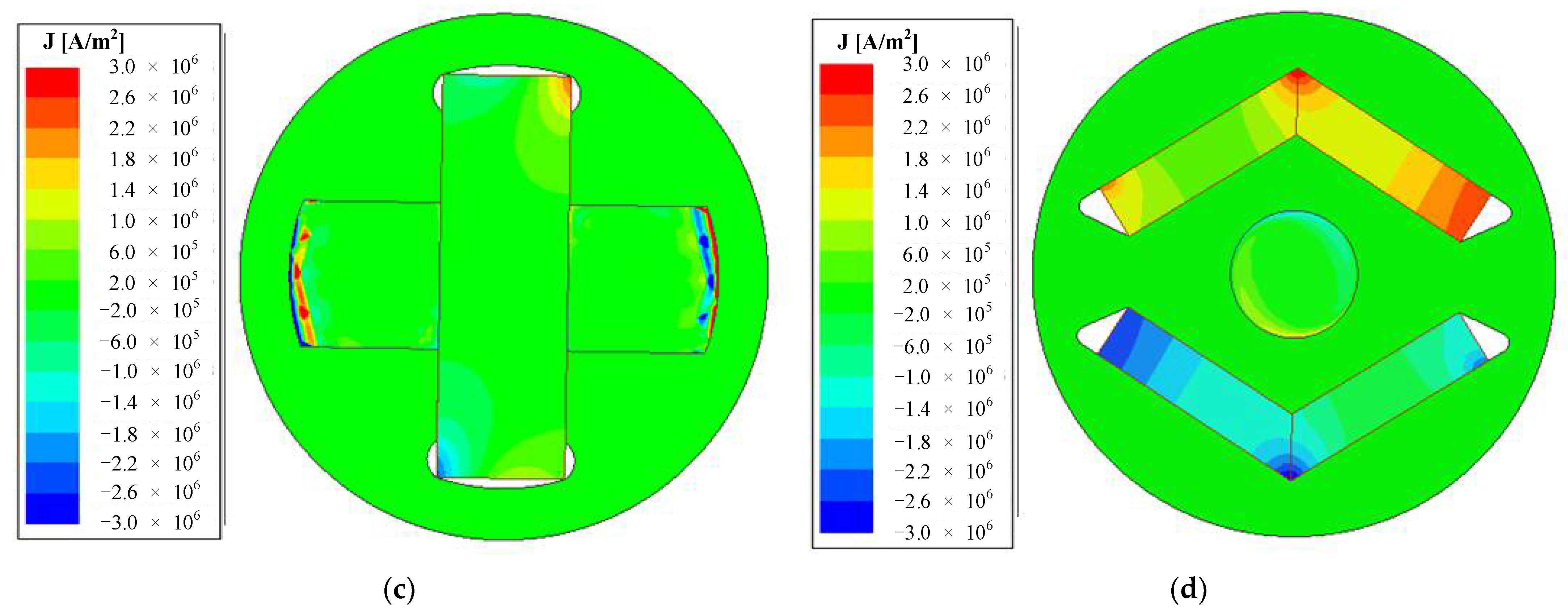
4.3. Eddy Current Loss

Table 1 and Table 2 show the bulk conductivity of rotor material. The rotor eddy current can be induced in the PM, sleeve, and rotor core, which is caused by space and time harmonics. Many methods were developed to reduce eddy current loss, including slotting sleeve, adding shield, and adopting a hybrid sleeve. An FEM is used to calculate rotor eddy current distribution, as shown in Figure 9. When the titanium alloy sleeve was employed, M1 had the highest eddy current loss, and the maximal eddy current loss occurred on the sleeve surface due to its high electrical conductivity. This is greatly challenging for developing cooling systems. M3 had the lowest eddy current loss on the PMs. Moreover, the eddy current loss of M2 and M4 was prominent in PMs. Maximal eddy current loss occurred at the end of PM, which increased the demagnetization risk to the PM.

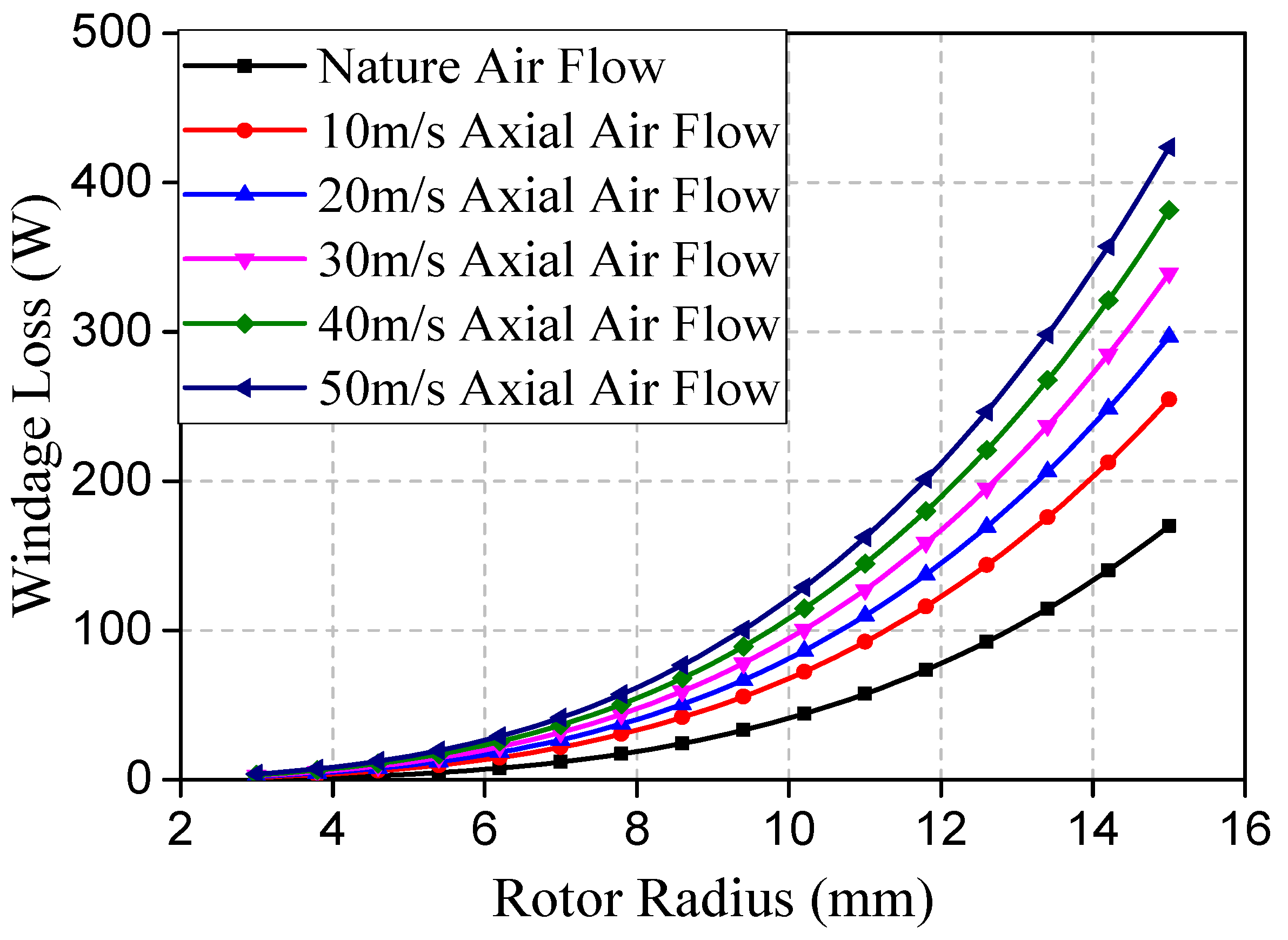
4.4. Mechanical Loss
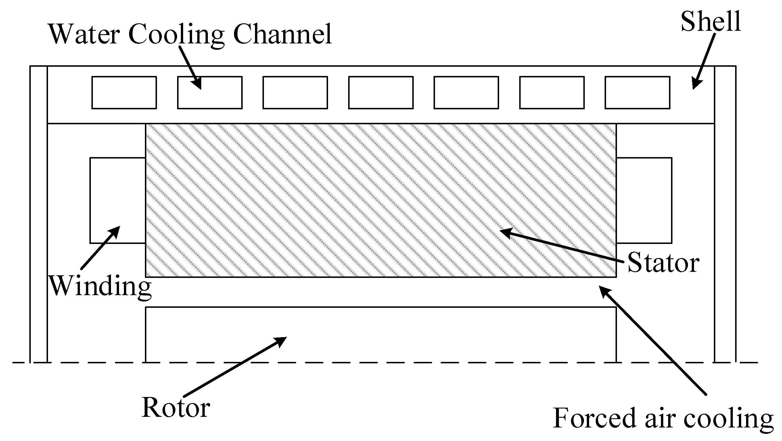
As the rotor is supported by airfoil bearing, and there is no mechanical contact between bearing and shaft, windage loss is the main component of mechanical loss. Windage loss can be calculated by the method proposed in [23]:
P w l = k C f π ρ ω 3 r 4 l ,
where k is the roughness coefficient, and its value is 1.0 for smooth surfaces; ρ is the air density; ω is rotor angular velocity; l is rotor axial length; and Cf is the friction coefficient, which depends on the cylinder radius of r.
The effect of tangential air flow as high-speed rotor rotation inside air gap can be expressed by Reynolds number
R e t = ρ ω r δ / μ ,
where μ is air dynamic viscosity, δ is the radial air gap length, and Ret is the Reynolds number.
For axial flow with additional cooling gas inside the air gap, the Reynolds number is expressed as
R e a = 2 ρ Q δ μ S a g ,
where Q is the flow rate of the cooling air, and Sag is the cross-sectional area of the air gap.
The friction coefficient within different flow speed levels of cooling air is calculated according to measurements in [16]:
C f = 0.515 δ / r 0.3 R e t 0.5 , 500 < R e t < 10 4 ,
C f = 0.0325 δ / r 0.3 R e t 0.2 , 10 4 < R e t ,
Windage loss induced by an additional axial flow of cooling air can be expressed as:
P a x = 0.67 π ρ r + δ 3 r 3 v a k a r ω 2 ,
where va is air flow velocity, and ka is the coefficient related to rotor roughness and stator surface, which was set to be 0.48 for the smooth surface. At a temperature of 100 °C and standard pressure of 0.1013 MPa, dynamic viscosity was 1.88 × 10⁻⁵ Ns/m2, air density was 1.29 kg/m3, and cooling air flow velocity was 15 m/s.
Windage loss is significantly influenced by cooling air velocity. Figure 10 shows rotor radius versus windage loss at different cooling air velocity levels. Windage loss with cooling air was higher than that without cooling air. As air velocity increases, windage loss also greatly increases. Therefore, for better performance at high-speed operation, appropriate axial air flow is required.
On the basis of the above analysis, the loss distribution and efficiency of HSPMSMs with different rotor structures at the rated state were obtained, as shown in Table 3. For these HSPMSMs, core and copper losses were the main components, but windage loss cannot be ignored. The total loss and efficiency of M2 were superior to those of other HSPMSMs, which means that M2 achieved better performance from this aspect. Although the efficiency of M1 was high, its rotor loss was also the highest. The main reason is that its rotor loss density was the highest due to its titanium alloy sleeve, which is a major challenge for HS applications. The efficiency of M3 and M4 was not as good due to the higher core loss.

5. Thermal Analysis

Improving the cooling method is an effective way to improve machine performance. In this paper, an efficient cooling method was adopted to improve the performance of HSPMSMs, as shown in Figure 11. A spiral waterway was used in the cooling water loop installed in the stator shell. The airway was set in the stator slots with axial ventilation. Table 2 shows the heat conductivity coefficients of the adopted materials in these machines. Ambient temperature was set to be 20 °C. As radiation heat translation slightly influences rotor temperature in nonvacuum environments, its effect was ignored in this paper.
According to heat transfer theory, the convective heat transfer coefficient between rotor surface and air gap of the machines could be calculated with
c a = N u λ δ ,
where ca is the heat transfer coefficient between rotor surface and air gap; λ is the air thermal conductivity; and Nu is the Nusselt number, which is a dimensionless number to represent the strength of convective heat transfer. Considering the HS rotation of the rotors, air flow in the air gap is accelerated in the tangential direction. The Nusselt number can be calculated with the following experimental correlation:
N u = 0.3387 R e a 1 / 2 P r 1 / 3 1 + ( 0.0468 / P r ) 2 / 3 1 / 4 ,
where Pr is the air Prandtl number at room temperature, which was set to be 0.692; and Rea is the Reynolds number. According to Equations (10) and (11), the convection heat transfer coefficient for the waterway in shell and the axial ventilation was 4058 and 651 W/m2/K, respectively.
To reduce the risk of irreversible PM demagnetization, the thermal field of these HSPMSMs was analyzed. The permissible maximal working temperature of the adopted PM needed to be below 180 °C. Therefore, for safety operation, the maximal operation temperature was limited to no more than 150 °C. The temperature distribution of these rotors at the rated load state were obtained on the basis of FEM, as shown in Figure 12. All these HSPMSMs were within the allowable temperature increase, and temperature distribution was generally consistent with loss distribution. M1 had the highest temperature increase due to its highest loss, while M3 had the lowest temperature increase. Maximal temperature that occurred at the end of PM in M4 was 123 °C.
The electromagnetic properties of PMs are highly sensitive to temperature, and temperature increase can cause irreversible demagnetization. Therefore, it is important to compare the temperature-dependent properties of different HSPMSMs. The B–H curve was derived from [24]. The permeability of the PM recoil line at any temperature could be calculated with a series of discrete data at reference temperature T0:
μ ( T ) = B i ( T , H ) H H = 0 + μ 0 = P ( T ) Q ( T ) μ i ( T 0 ) + μ 0 ,
where
B i ( H , T ) = P ( T ) ( b 0 tanh ( H + Q ( T ) H c i ( T 0 ) Q ( T ) h 0 ) + b 1 tanh ( H + Q ( T ) H c i ( T 0 ) Q ( T ) h 1 ) ,
P ( T ) = 1 + α 1 ( T T 0 ) + α 2 ( T T 0 ) 2 ,
Q ( T ) = 1 + β 1 ( T T 0 ) + β 2 ( T T 0 ) 2 ,
where coefficients α1, α2, β1, and β2 are provided by the material supplier. b0, b1, h0, and h1 were derived by the nonlinear curve fitting on the basis of the PM B–H curve at reference temperature T0.
The effects of the temperature variation on the torque performance of HSPMSMs were investigated in the above model. Figure 13 shows the electromagnetic torque under the rated current excitation when the PM temperature varied as follows: initial temperature was 20 °C; after 20 ms, it was increased to the maximal temperature; and after 20 ms, it decreased back to 20 °C. The torque could not recover to its previous value when the temperature returned to the previous value. Table 4 shows the influence of temperature variation on torque performance. Obviously, M2 had the minimal torque reduction at maximal temperature, and M3 had higher torque after returning to 20 °C due to its lower temperature dependency.

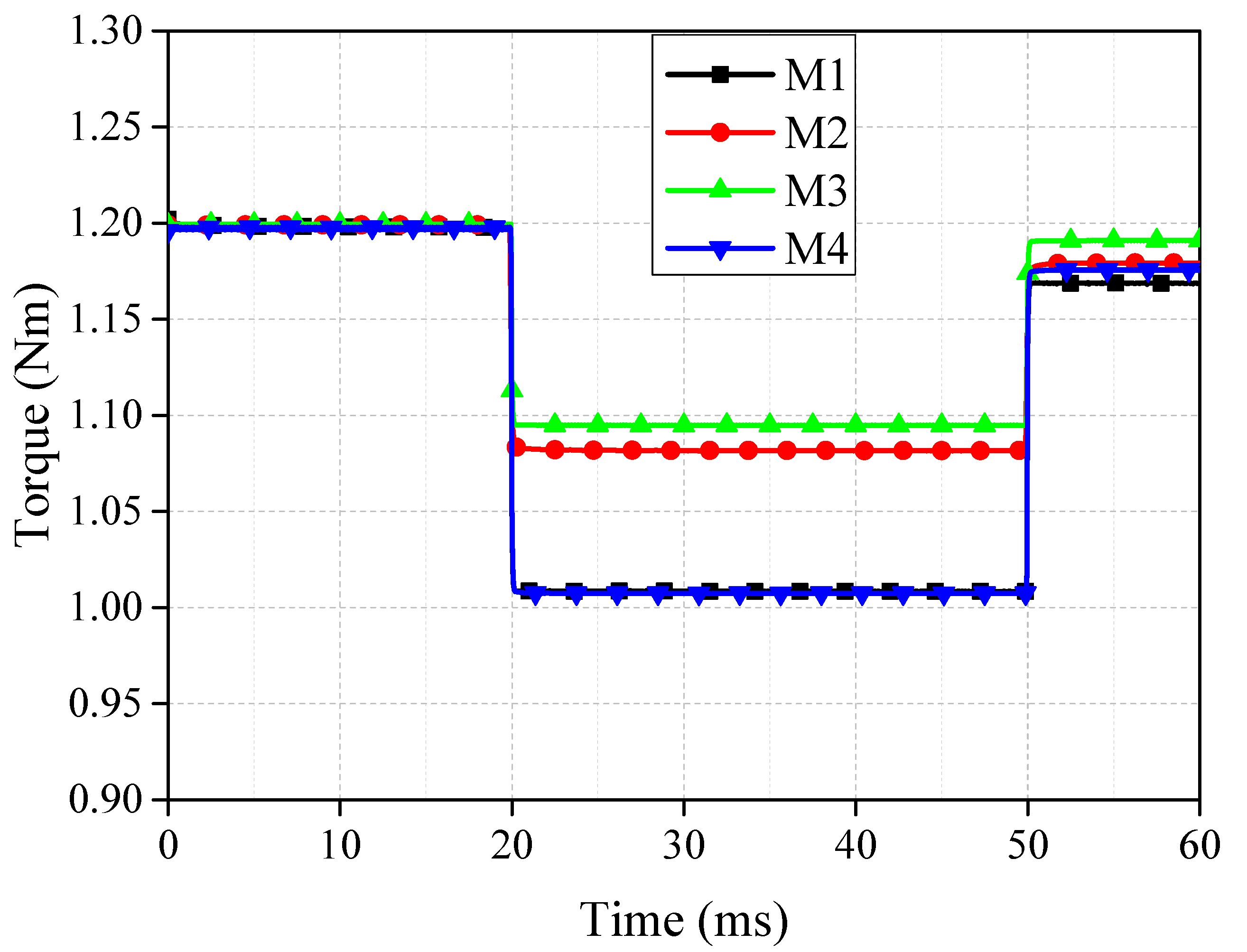
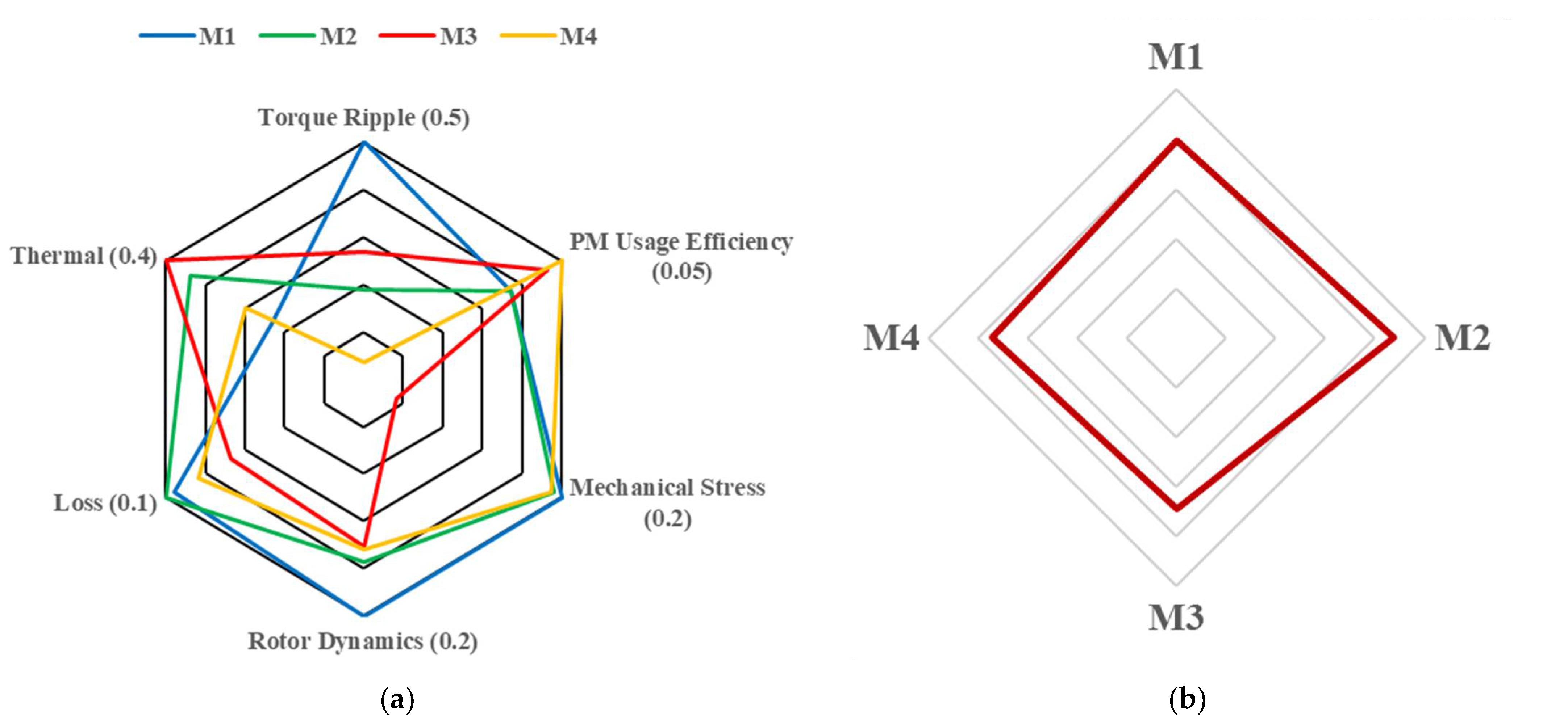
6. Results and Discussion

In this paper, four HSPMSMs with different rotor topologies for fuel-cell electric-vehicle application were designed, analyzed, and compared in terms of electromagnetism, mechanology, rotor dynamics, and thermotics. For a more intuitive conclusion, the effective performance of these HSPMSMs was compared by using a weighted-average method. Multiple objectives were converted into single objective by using the weighted-average method. The weight mean of finite multiset of objectives [x1, x2, …, xn} with corresponding non-negative weights [ω1, ω2, …, ωn] can be expressed as follows:
m ¯ = i = 1 n x i ω i i = 1 n ω i ,
when the weights were normalized, such that they summed up to 1, Equation (16) was simplified as:
m ¯ = i = 1 n x i ω i ,
In this section, all results are quantified and assigned weighted coefficients in which the relative importance of each target was determined on the basis of the above FEA results. The score of the weighted average represents the relative importance of different targets and is more descriptive than a simple average. This smooths out the data and improves result accuracy. The weight coefficient is determined by the target application; for different applications, the coefficient is quite different. Therefore, for a determined application, a set of weight coefficient can be assigned, and the final score can then be obtained. For example, to drive an HS compressor for fuel cell, electromagnetic performance is assigned with a larger coefficient. However, for turbocharger driving applications, thermal performance attracts more attention. Taking the application of compressor for fuel cells as an example, the score of the optimal result at each viewpoint was 100. Other results were quantified on the basis of the above method. Figure 14a shows the quantitative comparison from the viewpoint of torque ripple, PM usage, thermal performance, etc. The numbers of the figure are their corresponding weights. Figure 14b shows the overall comparison of weighted means considering the corresponding weights. The merits of different HSPMSMs are shown via the quantitative results, and the best topology could then be determined for the corresponding applications.

7. Conclusions

Four HSPMSMs with different rotor topologies were designed, analyzed, and compared in this paper. To reduce the operational frequency of HSPMSMs, all these HSPMSMs were designed with 6 stator slots and 2 rotor poles. The following conclusions could be drawn from the results of multiple physical field simulations:
(1)
As the rotor diameter of M1 was the smallest, it presented better electromagnetic and mechanical performance. However, it showed poor temperature behavior due to its high loss density. Meanwhile, this topology was the most difficult solution to implement. So, it is only suitable for low-power applications.
(2)
The rotor structure of M2 was very simple to implement; thus, its manufacturing process was easier, and its loss was much lower than that of other HSPMSMs. It achieved quite good electromagnetic, thermal, and mechanical performance. In most applications, M2 is a popular solution.
(3)
Both M3 and M4 were relatively easy to fabricate since no sleeve was required. On the other hand, as high-silicon sheets were adopted, the rotor loss of these two machines was high. Considering the rotor temperature distribution, M4 faced a great risk of irreversible demagnetization. Though M3 and M4 are not suitable for fuel-cell electric-vehicle air compressor applications, they could be designed with better comprehensive performance under different weights.
(4)
The weighted-average method was used to judge the performance of these HSPMSMs. For different applications, a different weighted coefficient could be applied, and the best topology could be obtained.
(5)
In further work, an interesting issue could be to refine the optimal analytical results, so that it could be better adapted to other HS applications while following the same process.

Author Contributions

Conceptualization, B.L., C.L. and J.Z.; writing—original draft preparation, B.L.; writing—review and editing, C.L., J.Z. and G.L.; supervision, Y.L. All authors have read and agreed to the published version of the manuscript.

Funding

This work was supported by the National Natural Science Foundation of China under project 52007047, and in part by the Outstanding Youth Innovation Project funded by State Key Laboratory of Reliability and Intelligence of Electrical Equipment EERI_OY2021005.

Institutional Review Board Statement

Not applicable.

Informed Consent Statement

Not applicable.

Data Availability Statement

Data are contained within the article.

Conflicts of Interest

The authors declare no conflict of interest.

References

  1. Lei, Q.; Geng, H.; Zhang, J.; Du, T.; Lv, H.; Yu, L. Design and Research of a Centrifugal Compressor for Automotive Fuel Cell Systems. In Proceedings of the 2018 IEEE International Conference on Mechatronics and Automation (ICMA), Changchun, China, 5–8 August 2018. [Google Scholar]
  2. Barta, J.; Uzhegov, N.; Losak, P.; Ondrusek, C.; Pyrhonen, J. Squirrel Cage Rotor Design and Manufacturing for High-Speed Applications. IEEE Trans. Electron. 2018, 66, 6768–6778. [Google Scholar] [CrossRef]
  3. Shen, J.; Qin, X.; Wang, Y. High-speed permanent magnet electrical machines—applications, key issues and challenges. CES Trans. Electr. Mach. Syst. 2018, 2, 23–33. [Google Scholar] [CrossRef]
  4. Sun, X.; Shi, Z.; Lei, G.; Guo, Y.; Zhu, J. Multi-Objective Design Optimization of an IPMSM Based on Multilevel Strategy. IEEE Trans. Electron. 2021, 68, 139–148. [Google Scholar] [CrossRef]
  5. Raminosoa, T.; Blunier, B.; Fodorean, D.; Miraoui, A. Design and Optimization of a Switched Reluctance Motor Driving a Compressor for a PEM Fuel-Cell System for Automotive Applications. IEEE Trans. Electron. 2010, 57, 2988–2997. [Google Scholar] [CrossRef]
  6. Gerada, D.; Mebarki, A.; Brown, N.L.; Gerada, C.; Cavagnino, A.; Boglietti, A. High-Speed Electrical Machines: Technologies, Trends, and Developments. IEEE Trans. Electron. 2014, 61, 2946–2959. [Google Scholar] [CrossRef]
  7. Uzhegov, N.; Kurvinen, E.; Nerg, J.; Pyrhonen, J.; Sopanen, J.T.; Shirinskii, S. Multidisciplinary Design Process of a 6-Slot 2-Pole High-Speed Permanent-Magnet Synchronous Machine. IEEE Trans. Electron. 2016, 63, 784–795. [Google Scholar] [CrossRef]
  8. Bartolo, J.B.; He, Z.; Gerada, D.; Lillo, L.D.; Gerada, C. High speed electrical generators, application, materials and design. In Proceedings of the 2013 IEEE Workshop on Electrical Machines Design Control and Diagnosis (WEMDCD), Paris, France, 11–12 March 2013. [Google Scholar]
  9. Zhang, F.G.; Du, G.H.; Wang, T.Y.; Liu, G.W.; Cao, W.P. Rotor Retaining Sleeve Design for a 1.12-MW High-Speed PM Machine. IEEE Trans. Ind. Appl. 2015, 51, 3675–3685. [Google Scholar] [CrossRef] [Green Version]
  10. Ahn, J.H.; Cheol, H.; Kim, C.W.; Choi, J.Y. Rotor Design of High-Speed Permanent Magnet Synchronous Motors Considering Rotor Magnet and Sleeve Materials. IEEE Trans. Appl. Supercond. 2017, 28, 5201504. [Google Scholar] [CrossRef]
  11. Fang, H.; Qu, R.; Li, J.; Zheng, P.; Fan, X. Rotor Design for High-Speed High-Power Permanent-Magnet Synchronous Machines. IEEE Trans. Ind. Appl. 2017, 53, 3411–3419. [Google Scholar] [CrossRef]
  12. Liu, Y.; Ou, J.; Schiefer, M.; Breining, P.; Grilli, F.; Doppelbauer, M. Application of an Amorphous Core to an Ultra-High-Speed Sleeve-Free Interior Permanent-Magnet Rotor. IEEE Trans. Electron. 2018, 65, 8498–8509. [Google Scholar] [CrossRef]
  13. Yunkai, H.; Jianguo, Z.; Youguang, G. Thermal Analysis of High-Speed SMC Motor Based on Thermal Network and 3-D FEA With Rotational Core Loss Included. IEEE Trans. Magn. 2009, 45, 4680–4683. [Google Scholar] [CrossRef]
  14. Uzhegov, N.; Smirnov, A.; Park, C.H.; Ahn, J.H.; Heikkinen, J.; Pyrhonen, J. Design Aspects of High-Speed Electrical Machines With Active Magnetic Bearings for Compressor Applications. IEEE Trans. Electron. 2017, 64, 8427–8436. [Google Scholar] [CrossRef]
  15. Du, G.; Xu, W.; Zhu, J.; Huang, N. Power Loss and Thermal Analysis for High-Power High-Speed Permanent Magnet Machines. IEEE Trans. Electron. 2020, 67, 2722–2733. [Google Scholar] [CrossRef]
  16. Zhang, Y.; McLoone, S.; Cao, W.; Qiu, F.; Gerada, C. Power Loss and Thermal Analysis of a MW High-Speed Permanent Magnet Synchronous Machine. IEEE Trans. Energy Convers. 2017, 32, 1468–1478. [Google Scholar] [CrossRef] [Green Version]
  17. Chebak, A.; Viarouge, P.; Cros, J. Improved Analytical Model for Predicting the Magnetic Field Distribution in High-Speed Slotless Permanent-Magnet Machines. IEEE Trans. Magn. 2015, 51, 8102904. [Google Scholar] [CrossRef]
  18. Tuysuz, A.; Meyer, F.; Steichen, M.; Zwyssig, C.; Kolar, J.W. Advanced Cooling Methods for High-Speed Electrical Machines. IEEE Trans. Ind. Appl. 2017, 53, 2077–2087. [Google Scholar] [CrossRef]
  19. Zhang, Z.; Yu, L.; Sun, L.; Qian, L.; Huang, X. Iron Loss Analysis of Doubly Salient Brushless DC Generators. IEEE Trans. Electron. 2015, 62, 2156–2163. [Google Scholar] [CrossRef]
  20. Zhao, N.; Liu, W. Loss Calculation and Thermal Analysis of Surface-Mounted PM Motor and Interior PM Motor. IEEE Trans. Magn. 2015, 51, 8112604. [Google Scholar] [CrossRef]
  21. Fang, J.; Liu, X.; Bangcheng, H.; Kun, W. Analysis of Circulating Current Loss for High-Speed Permanent Magnet Motor. IEEE Trans. Magn. 2015, 51, 8200113. [Google Scholar] [CrossRef]
  22. Van der Geest, M.; Polinder, H.; Ferreira, J.A.; Zeilstra, D. Stator winding proximity loss reduction techniques in high speed electrical machines. In Proceedings of the IEEE International Electric Machines and Drives Conference (IEMDC), Chicago, IL, USA, 12–15 May 2013; pp. 340–346. [Google Scholar]
  23. Zhang, Y.; McLoone, S.; Cao, W. Electromagnetic Loss Modeling and Demagnetization Analysis for High Speed Permanent Magnet Machine. IEEE Trans. Magn. 2018, 54, 8200405. [Google Scholar] [CrossRef]
  24. Guo, B.; Huang, Y.; Peng, F.; Dong, J. General Analytical Modeling for Magnet Demagnetization in Surface Mounted Permanent Magnet Machines. IEEE Trans. Electron. 2019, 66, 5830–5838. [Google Scholar] [CrossRef] [Green Version]
Figure 1. 19 kW HSPMSM configuration. (a) M1, rotor with a solid PM cylindrer; (b) M2, rotor with segmented magnet; (c) M3, rotor with interior magnet; (d) M4, rotor with V-shaped interior magnet; (e) stator.
Applsci 12 04375 g001aApplsci 12 04375 g001b
Figure 2. Back-EMF and flux-linkage waveforms for HSPMSM with different rotors at no-load condition. (a) Waveforms. (b) spectral analysis; (c) flux linkage waveform.
Applsci 12 04375 g002
Figure 3. HSPMSM torque with different rotors at no-load. (a) Waveforms; (b) spectral analysis.
Applsci 12 04375 g003
Figure 4. Mechanical stress distribution in the rotor at rated operation conditions (160 krpm). (a) M1; (b) M2; (c) M3; (d) M4.
Applsci 12 04375 g004
Figure 5. Total deformation distribution in the rotor at rated operation conditions (160 krpm). (a) M1; (b) M2; (c) M3; (d) M4.
Applsci 12 04375 g005
Figure 6. Influence of the critical speed on bearing stiffness.
Applsci 12 04375 g006
Figure 7. Campbell diagram of HSPMSMSs with different rotors. (a) M1; (b) M2; (c) M3; (d) M4.
Applsci 12 04375 g007
Figure 8. ksp versus ratio of wire thickness to skin depth at different frequencies.
Applsci 12 04375 g008
Figure 9. Eddy-current loss distribution in rotor at rated state (160 krpm). (a) M1; (b) M2; (c) M3; (d) M4.
Applsci 12 04375 g009aApplsci 12 04375 g009b
Figure 10. Windage loss under different cooling conditions.
Applsci 12 04375 g010
Figure 11. Cooling method.
Applsci 12 04375 g011
Figure 12. Temperature distribution on rotor of HSPMSMs at rate load. (a) M1; (b) M2; (c) M3; (d) M4.
Applsci 12 04375 g012
Figure 13. Electromagnetic torque with temperature variation.
Applsci 12 04375 g013
Figure 14. Comparison of different HSPMSMs. (a) Quantitative comparison considering single target; (b) overall comparison.
Applsci 12 04375 g014
Table 1. HSPMSM specifications.
ParameterSymbolValueUnit
Rate powerPn19kW
Rate speednn160krpm
Current densityCn10A/mm2
Rate torqueTn1.1Nm
Efficiencyη>95%-
Frequencyfn2666Hz
Number of polesp2-
Number of slotsQS6-
No. of turns per coilNs20-
Stator outer diameterDso80mm
Core stack lengthL80mm
Air gapδag2mm
PM materialNdFeB (N42SH)--
PM remanenceBre1.05T
PM relative permeabilityμ1.05-
Bulk conductivityσPM646,381S/m
Table 2. Main parameters and material properties of HSPMSMs.
ParameterM1M2M3M4
Initial outer diameter (mm)15–2515–2515–2515–25
Optimized outer diameter (mm)15.81821.421.4
PM thickness (mm)5.94.15.22.3
Shaft diameter (mm)-8.8-5.2
PM length (mm)--16.416.2
Sleeve materialTi-6Al-4VCFC10JNEX90010JNEX900
Density (kg/m3)4428180073507350
Young’s modulus (GPa)124.6125200200
Poisson’s ratio0.330.280.290.29
Permitted stress (MPa)10001300>700>700
Bulk conductivity (S/m)591,57220,0001,219,5101,219,510
Thermal conductivity (W/(m·K))8.50.73939
Table 3. Loss distribution of HSPMSMs with different rotors.
Loss DistributionM1M2M3M4
Core loss (W)212.34115.87237.54242.12
Copper loss (W)202.58208.05208.05208.05
Windage loss (W)37.2558.2497.697.6
Rotor loss (W)45.1215.115.918.95
Total loss (W)495.73397.27594.09566.72
Efficiency97.39%97.91%97.11%97.01%
Table 4. Influence of temperature variation on torque performance.
TopologyTorque Reduction at Maximal TemperatureTorque Reduction after Returning 20 °C
M115.80%2.45%
M27.56%1.66%
M38.71%0.72%
M416.45%1.80%
Publisher’s Note: MDPI stays neutral with regard to jurisdictional claims in published maps and institutional affiliations.

