Article

Performance of the Compliant Foil Gas Seal with Surface Micro-Textured Top Foil

College of Petroleum and Chemical Engineering, Lanzhou University of Technology (LUT), Lanzhou 730050, China
*
Author to whom correspondence should be addressed.
Appl. Sci. 2022, 12(11), 5633; https://doi.org/10.3390/app12115633
Submission received: 2 April 2022 / Revised: 28 May 2022 / Accepted: 30 May 2022 / Published: 1 June 2022
(This article belongs to the Section Fluid Science and Technology)

Abstract

:

Featured Application

Compliant foil gas seals, as a non-contact sealing mechanism with high self-adaptability, are used in the main bearing cavity of aero engines.

Abstract

In various fields, micro-textures have been successfully applied to the surface of friction pairs to effectively improve flow field and friction performance. This paper aims to investigate how different textures affect the sealing performance of compliant foil gas film seals. In theoretical simulations, a facile method for characterizing the shape of micro-textures is proposed, and the equilibrium relationship between the gas film pressure, gas film thickness, and foil deformation is established. The transient Reynolds equation considering the eccentric convergence problem and abrupt Rayleigh step changes is solved to analyze the static and dynamic characteristics. The results show that (i) compared with the directionality of the texture, the gas volume accommodated by the texture has a greater impact on the sealing performance, and a convergent texture can effectively control the leakage rate; (ii) when the texture depth exceeds 9 μm, the sealing system may be unstable; (iii) the compliant foil seal is well suited to higher-speed service conditions, and the inverted triangular texture shows the best comprehensive sealing performance.

1. Introduction

As an aircraft is susceptible to random uncertainty excitation during operation [1], which may induce seal instability or failure, designing a seal structure with good high-speed stability and strong autonomous adjustment capability is of great importance for the development of aerospace engines. The compliant foil seal (CFS) is a new type of non-contact seal [2]. Compared with the traditional gas film sealing structure, which has a rigid floating ring, the compliant foil can undergo adaptive deformation under load; moreover, there is Coulomb friction between the contact elements [3,4]. Owing to these advantages, the sealing structure can rapidly adapt to the operating position, spontaneously adjust the balanced relationship between the friction pair, load, and gas film, ensure gas film stability, and prevent friction and collision. Therefore, a sealing structure with a compliant sealing surface or flexible support has considerable potential for application in the sealing components of rocket turbine pumps and aero-engine systems [5,6].
In the 1990s, Salehi and Heshmat proposed a CFS structure based on the study of foil bearings, and they tested it at 55,000 rpm and 560 °C [7,8,9]. Regarding the theoretical study, they established the governing equation of the film pressure by considering the turbulence effect and analyzed the sealing performance of CFS under high-speed operation conditions using the method of successive over-relaxation [10]. Kim [11] combined the perturbation method for a floating ring seal with the finite element method for a flexible foil to analyze its characteristics and found that the eccentricity decreases while the direct stiffness and damping coefficient increases as the bump foil thickness increases. Lee et al. [12] designed a floating ring seal structure using a bump foil to support the ring, which demonstrated its stability at high speed through eddy current stability experiments. Ding [13] used the PH linear method to study the steady-state flow field characteristics of a cylindrical spiral-groove gas film seal and found that the sealing pressure difference has a significant effect on the steady-state characteristics. Wang [5] analyzed the sealing characteristics and dynamic properties of CFS and tested the effect of different surface roughness values on the start-stop cycle performance of high-speed elastic foil sealing [14]. The results showed that improving the interface surface properties can effectively attenuate the hysteresis effect of the seal.
Interface modeling of the friction pair has a significant impact on the flow field, dynamic pressure effect, and friction performance [15,16]. Stull’s [17] introduction of a series of cavities in the diverging curved walls of a two-dimensional ribbed diffuser or Mariotti’s [18] application of transverse grooves on both sides of the stern side can produce locally stable flow re-circulation. The textured surface of the diamond-like carbon film is machined on the dry gas seal ring, and its trapping effect contributes significantly to the improvement of friction performance [19,20]. Moreover, the parameters of pits are the keys to affecting friction performance [19,21]. The shape design of the texture successfully utilizes the knowledge of biomimicry; for instance, streamlined grooves in dolphin skin were used by Lang [22] and a semi salix leaf textured face was processed by Bai [23]. With the widespread application of texture, optimization or hybrid processing techniques such as mask deposition and laser cladding are gradually developed [24]. Thus far, research on the surface modeling of friction pairs of the cylinder gas seal has mainly focused on the design of dynamic pressure grooves [25,26,27]. Most of these studies have used CFD software, where procedures such as geometric modeling and mesh division are relatively cumbersome.
In summary, research on the characteristics of compliant foil gas seals has mainly focused on structural design. Although some researchers have conducted theoretical analyses and experimental tests, results on the accurate design of the micro-textures on the surfaces of compliant foil gas seals are relatively scarce. In the present study, numerical modeling was used to calculate the flow field distribution of the compliant foil gas seal, and to evaluate the influence of micro-texture shapes, depth, and rotational speed on the sealing performance. With these works done, the optimal matching method can be determined.

2. Materials and Methods

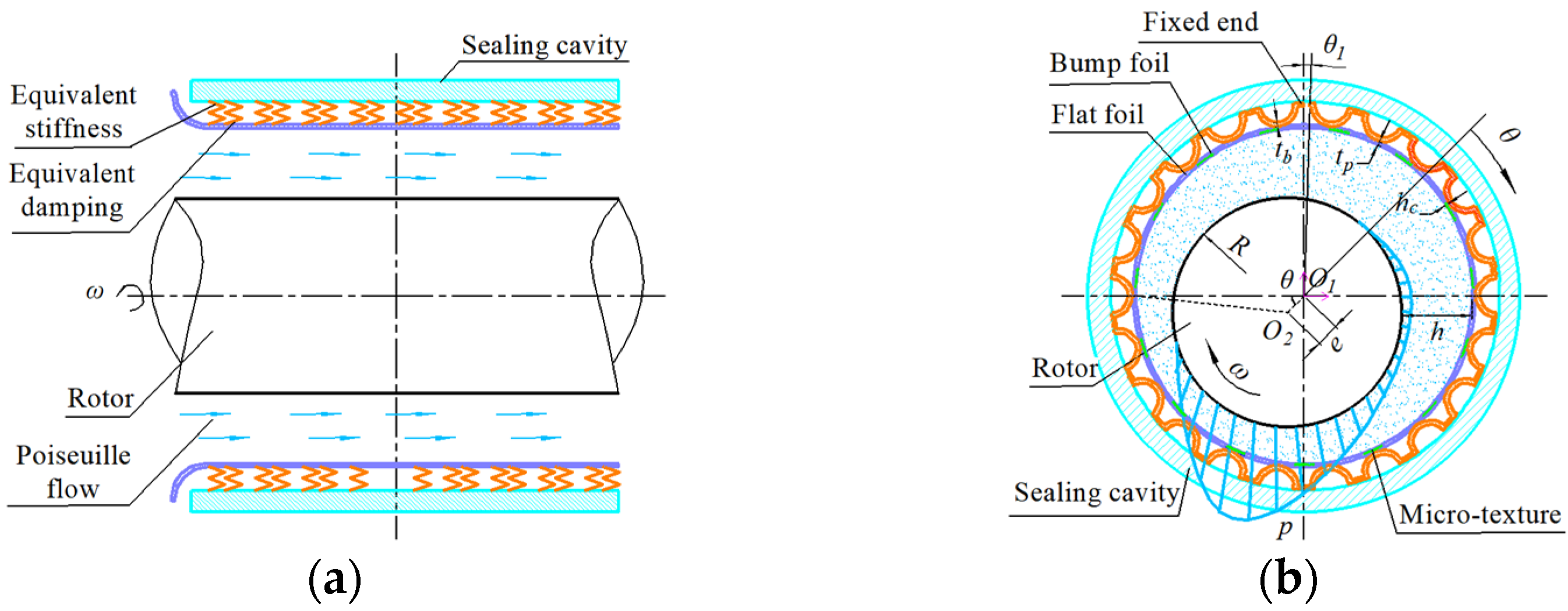
2.1. Geometric Model

The structure of the compliant foil gas seal is shown in Figure 1. It mainly consists of a sealing cavity, flexible sealing surface, and rotating shaft. The flexible sealing surface includes a bump foil and a top foil with flexible support. The top foil is bent on the high-pressure side to form an extension, which serves to fix the foil and block the leakage channel.
In Figure 1, θ1 is the angle between the free end of the bump foil and the fixed end, p is the gas film pressure, h is the thickness of the gas film, tb and tp are the thicknesses of the bump foil and the flat foil, respectively, hc is the texture depth, e is the eccentricity distance, R is the outer diameter of the rotation axis, and O1 and O2 are the centers of the sealing cavity and the rotation axis, respectively.
The rotor is installed eccentrically in the sealing cavity. When the compliant foil gas seal is in the normal working condition, the bump foil and top foil are slightly deformed under the viscous shear of the sealing medium, as shown in Figure 2a. A micro-scale wedge-shaped gap of 10–30 μm is formed between the friction pairs, which separates the friction and sealing pairs and produces a good hydrodynamic pressure effect, thereby forming a rigid pressurized air film to achieve lubrication and sealing. The structural parameters of the bump foil are shown in Figure 2b.
In Figure 2b, u, rb, s, l, and α are the deformation, radius, pitch, half chord length, and wrapping angle of the foil, respectively, and L is the seal width.

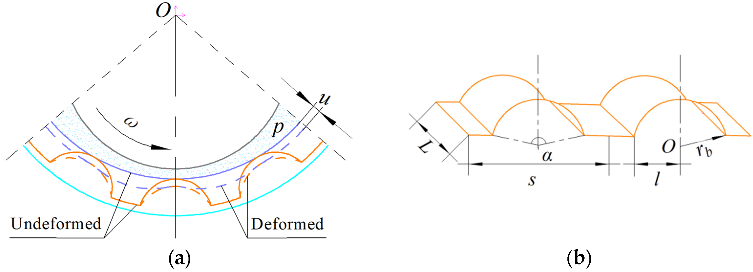
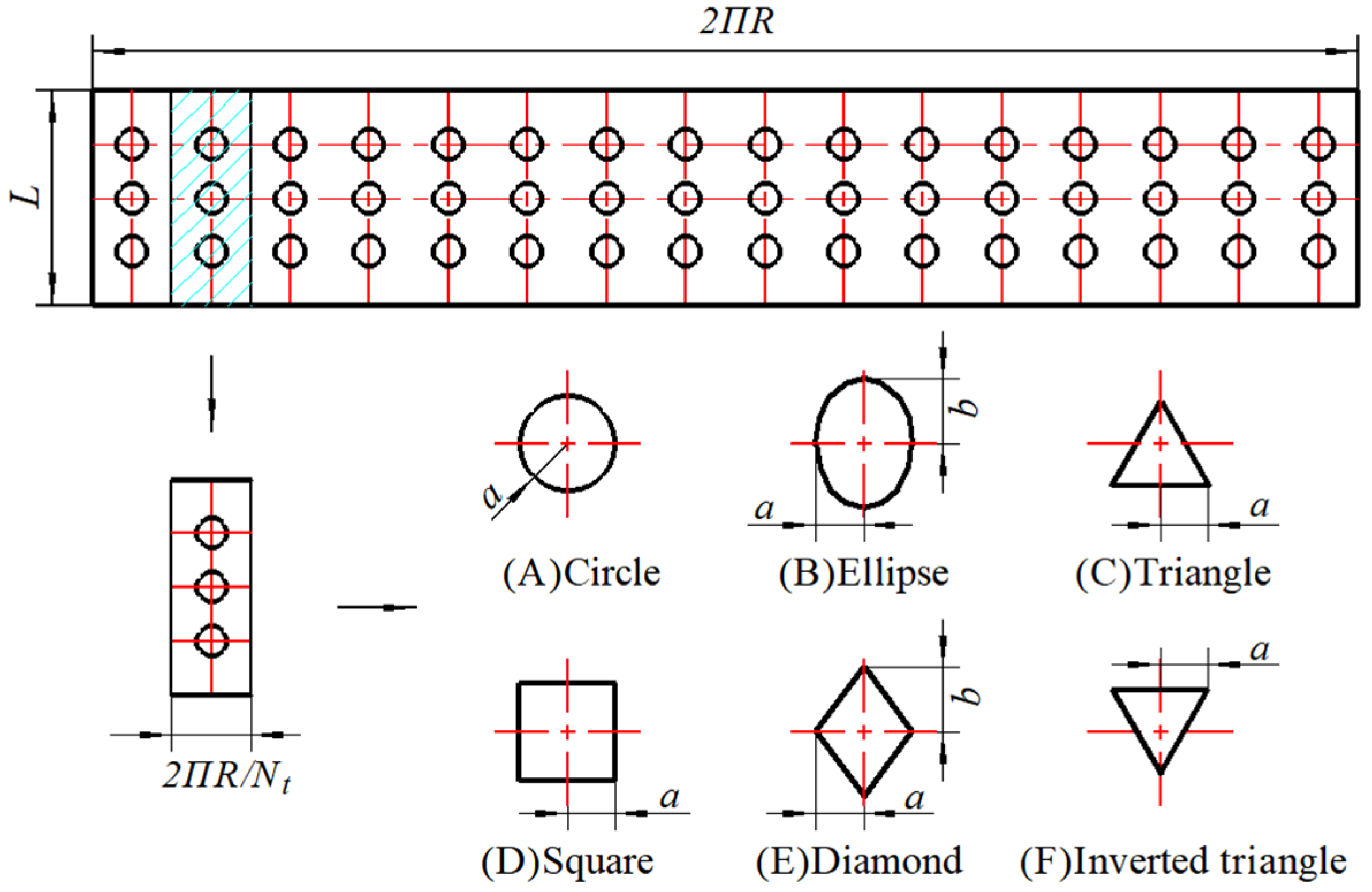
2.2. Micro-Texture Model

The upper surface of the flat foil is in contact with the sealing medium, and micro-textures are formed on the surface via laser marking, as shown in Figure 3, where L is the seal width, a and b are the structural parameters of the texture, Nt is the number of cycles. When acquiring surface data, the texture first needs to be drawn on a 1:1 scale. Then, the image is converted into a series of matrices by the recognition method; the size of the matrix is consistent with the size of the flow field matrix.

3. Theoretical Model

3.1. Reynolds Equation and Gas Film Thickness Control Equation

The compliant foil gas seal problem can be categorized as a micro-scale flow field problem. Therefore, the flow field can be considered as a laminar flow in this study. Moreover, the following assumptions are made: there is no slip at the fluid-solid interface, the sealing medium is an ideal gas, and the physical parameters remain unchanged. The pressure solution model can be obtained as follows:
θ P H 3 P θ + R L 2 Z P H 3 P Z = Λ ( P H ) θ + 2 γ Λ ( P H ) T
Considering the Coulomb friction between the bump foil and the sealing cavity and ignoring the concavity or convexity of the flat foil in the radial direction, Iordanoff’s [28] stiffness model with one end fixed and one end free is used to characterize the deformation of the bump foil. Thus, the static film thickness formula can be obtained as follows:
H = 1 + ε cos θ + H c + ( P 1 ) K b ( θ , Z ) Textured   region 1 + ε cos θ + ( P 1 ) K b ( θ , Z ) Non-textured   region
The dimensionless parameters are defined as follows:
Z = z L ,   H = h h 0 ,   P = p p a ,   T = τ t ,   Λ = 6 ω μ r 2 p a h 0 2 ,   γ = τ ω ,   H c = h c h 0 ,   K b = k b h 0 p a
where z is the axial coordinate, t is the motion time, kb is the bump foil stiffness, h0 is the average gas film thickness, pa is the ambient pressure, τ is the angular velocity of the vortex, μ is the viscosity of the lubricant gas, γ is the perturbation ratio, Λ is the compressibility coefficient, ε is the eccentricity, and P, Z, H, T, Hc, and Kb are the corresponding dimensionless parameters.
After the displacement perturbation and velocity perturbation at the equilibrium position, the dimensionless perturbation is obtained as follows:
Δ X = Δ x h 0 = Δ X e i T ,   Δ Y = Δ y h 0 = Δ Y e i T
The Taylor series expansions for the gas film pressure, gas film thickness, and foil deformation with the perturbation parameters are expressed as follows:
P t = P + P x Δ X + P x Δ X ˙ + P y Δ Y + P y Δ Y ˙ H t = H + H x Δ X + H x Δ X ˙ + H y Δ Y + H y Δ Y ˙ U t = U + U x Δ X + U x Δ X ˙ + U y Δ Y + U y Δ Y ˙
After considering the time term, the gas film thickness deviates from the static gas film thickness H, and the gas film thickness under perturbation is obtained as follows:
H t = H + ( Δ X sin θ Δ Y cos θ ) + Δ U t
Combining Equations (5) and (6), the following can be deduced:
H x = U x + sin θ , H x = U x H y = U y cos θ , H y = U y
According to the relationship between the gas film pressure and the deformation of the bump foil, the following can be obtained:
P = K b U + C b γ U T + 1
Substituting Equations (5) and (7) into Equation (8) gives the following equation, where Cb is the dimensionless damping of the foil:
P x = K b H x C b H x K b sin θ P x = K b H x + C b h x C b sin θ ,   P y = K b H y C b H y + K b cos θ P y = K b H y + C b H y + C b cos θ

3.2. Boundary Conditions

The mandatory boundaries at the inlet and outlet locations are expressed as follows, where pi is the inlet pressure:
Z = 0 , P = p i p a , P x = P x = P y = P y Z = L , P = 1 , P x = P x = P y = P y
The circular boundary in the middle section is expressed as follows:
P ( θ , Z ) = P ( θ + 2 π , Z ) P x ( θ , Z ) = P x ( θ + 2 π , Z ) , P x ( θ , Z ) = P x ( θ + 2 π , Z ) P y ( θ , Z ) = P y ( θ + 2 π , Z ) , P y ( θ , Z ) = P y ( θ + 2 π , Z )

3.3. Static Sealing Performance Parameters

The key static characteristics parameters for evaluating the compliant foil gas seal are the gas film force F, mass leakage rate Q, attitude angle φ, and friction force Ff. In the following equations, the subscripts h and v represent the horizontal and vertical directions, respectively:
F h , v = 0 L 0 2 π ( p p a ) r cos θ sin θ d θ d z ,   F = F h 2 + F v 2
Q = 0 2 π ρ h 3 12 μ p z r d θ
φ = a c t tan F v F h
F f h , v = 0 L 0 2 π ( p r θ h 2 p + μ ω r h ) r cos θ sin θ d θ d z ,   F f = F f h 2 + F f v 2

3.4. Dynamic Sealing Performance Parameters

The dynamic characteristic parameters for evaluating the stability of the compliant foil gas seal are the direct stiffness coefficients kxx and kyy, direct damping coefficients cxx and cyy, cross stiffness kxy and kyx, cross damping coefficients cxy and cyx, which are expressed as follows:
k x x k x y k y x k y y = R L p a h 0 0 1 0 2 π P x cos θ P y cos θ P x sin θ P y cos θ d θ d Z
c x x c x y c y x c y y = R L p a h 0 τ 0 1 0 2 π P x cos θ P y cos θ P x sin θ P y cos θ d θ d Z

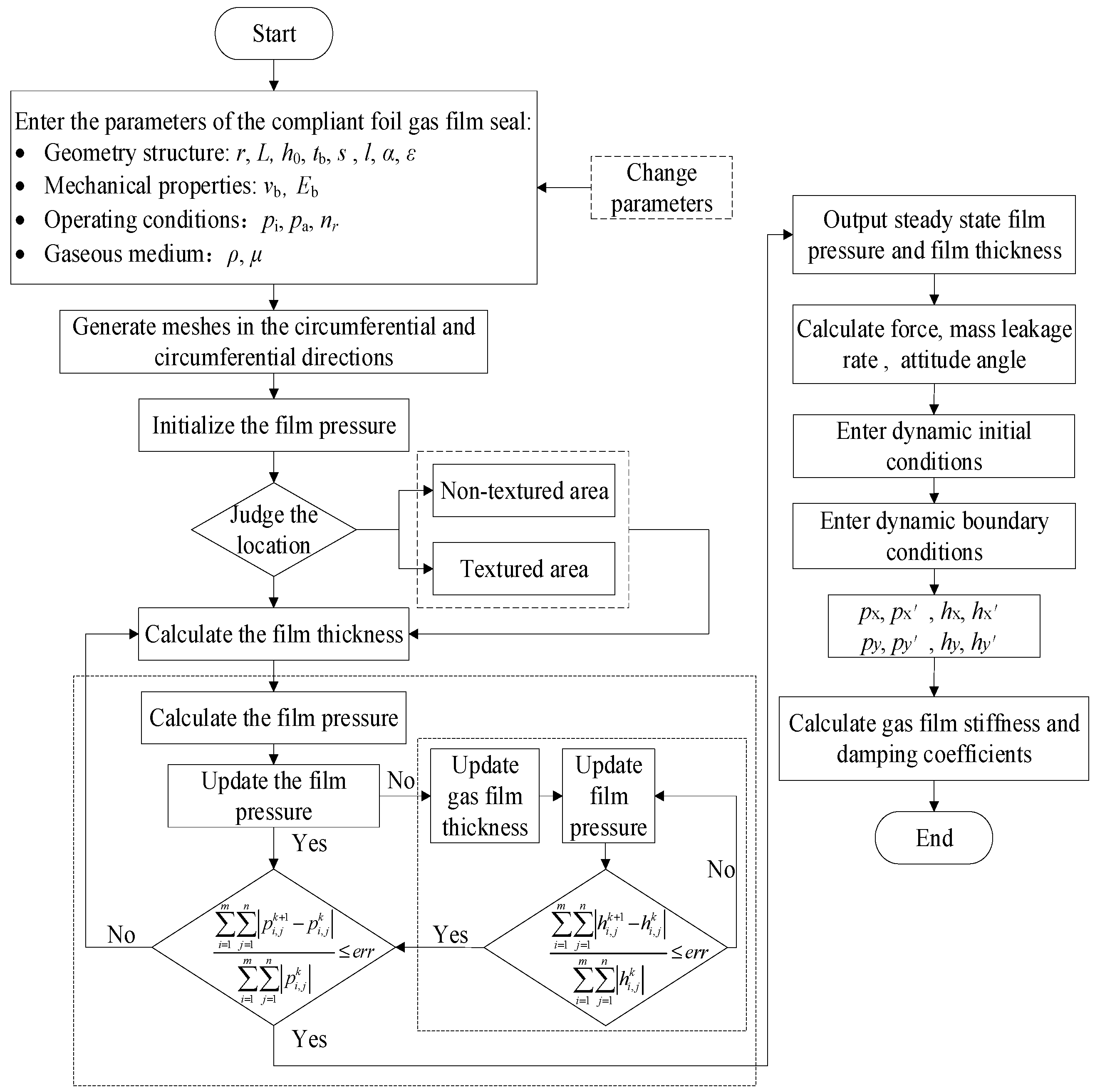
3.5. Calculation Flow

The flow chart for calculating the characteristic parameters of the compliant foil gas seal is shown in Figure 4.

3.6. Parameters Selection

The geometric structure and mechanical performance parameters of the compliant foil gas seal used in the calculation in this study are summarized in Table 1, and the operating parameters are listed in Table 2, where ρ is the viscosity of the lubricant gas and μf is the friction factor.

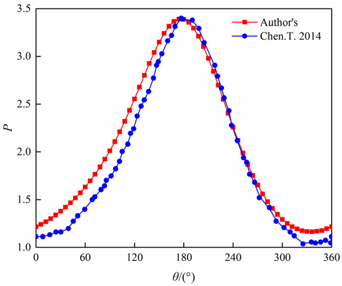
3.7. Program Correctness Verification

The structural parameters of the non-slotted rigid floating ring used in the literature [29] are selected to verify the correctness of the flow field calculation program. The comparison results obtained when the eccentricity is 0.5 and the inlet pressure is 0.20 MPa are shown in Figure 5. The results of the two calculations are similar, which verifies the correctness of the calculation procedure in this study.

4. Results

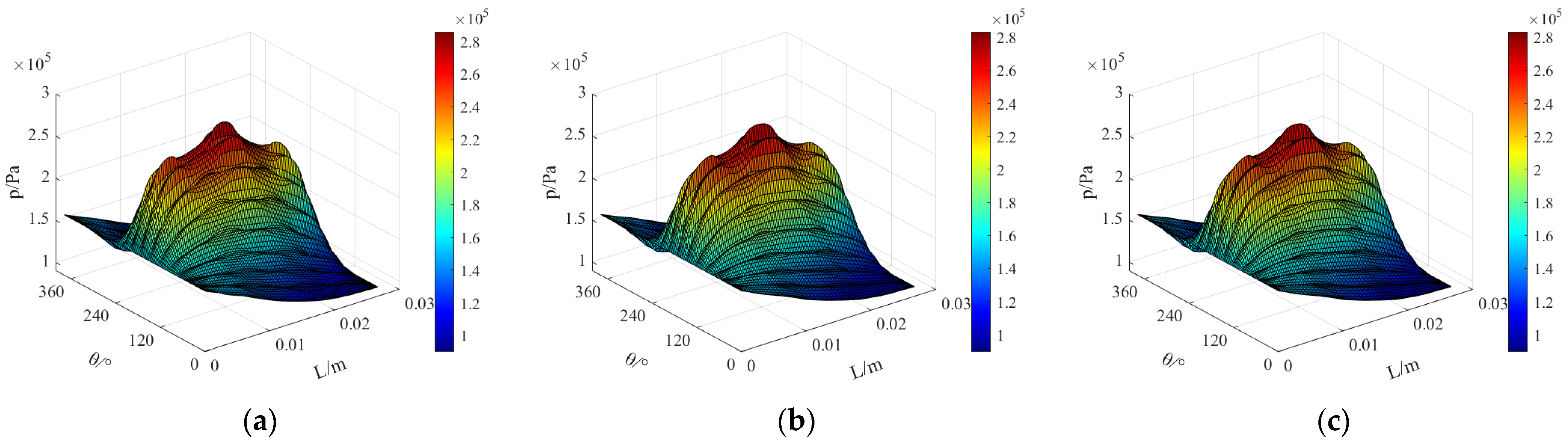
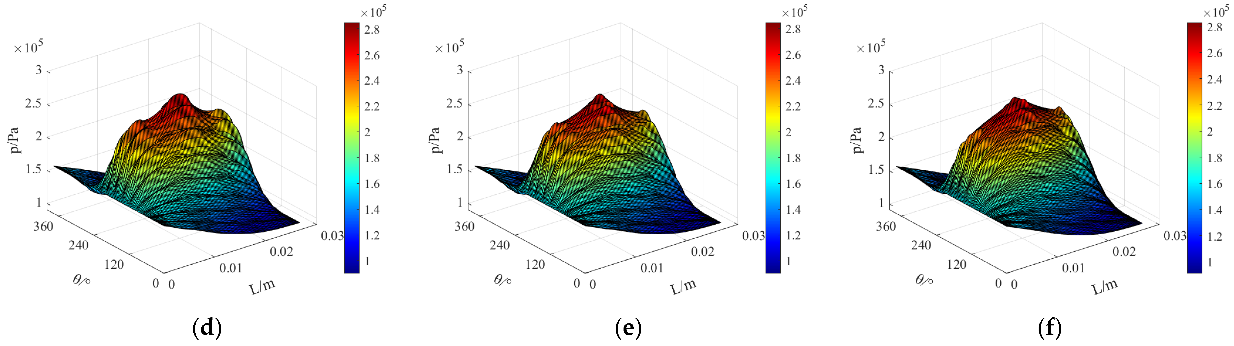
4.1. Distribution of the Gas Film Thickness and Gas Film Pressure

Using the parameters listed in Table 1 and Table 2 for calculation, the thickness and pressure distribution of the gas film are obtained as shown in Figure 6 and Figure 7, respectively. As can be seen, the minimum thickness of the gas film is attained at the pressure outlet position of θ = 180°. The pressure of the gas film is subject to a combination of the dynamic pressure effect and the wedge effect, and the pressure gradually decreases along the axial direction from the inlet until it reaches the ambient atmospheric pressure at the outlet of the sealing end face. Negative pressure appears near the higher region of the gas film pressure. Both the squeezing effect of the positive pressure and the adsorption effect of the negative pressure cause deformation of the bump foil.
Additionally, it can be seen from the pressure data in Figure 7 that the maximum pressure peak is 0.29 MPa for the circular texture, and the peaks of the maximum pressure for different textures are ordered from largest to smallest as: circle > square > diamond > ellipse > inverted triangle > triangle. The minimum pressure valley is 0.09 MPa for elliptical texture, and the valleys for different textures are ordered from smallest to largest as: ellipse < diamond < square < circle < inverted triangle < triangle. Figure 7c,f show that the triangular texture is a “narrow-to-wide” divergent texture while the inverted triangular texture is a “wide-to-narrow” convergent texture. After the gas flows into the inverted triangular micro-pit, it expands and slows down initially; then, owing to the sharp reduction of the flow channel, the direction of the velocity suddenly changes quite abruptly, and a large secondary dynamic pressure effect is formed when the gas flows out of the micro-pit. As can be seen, the directionality of the texture affects the pressure distribution even if the texture areas are equal. By contrast, the circular texture in Figure 6a and the square texture in Figure 6d, which correspond to a more regular shape, do not significantly change the velocity direction. For the elliptical texture in Figure 6b and the diamond-shaped texture in Figure 6e, the length in the axial direction is greater than that in the circumferential direction, which has a certain diversion effect.
Figure 6. The thickness of the gas film with (a) circular texture (b) elliptical texture (c) triangular texture (d) square texture (e) diamond-shaped texture and (f) inverted triangular texture.
Applsci 12 05633 g006
Figure 7. The pressure of the gas film with (a) circular texture (b) elliptical texture (c) triangular texture (d) square texture (e) diamond-shaped texture and (f) inverted triangular texture.
Applsci 12 05633 g007aApplsci 12 05633 g007b

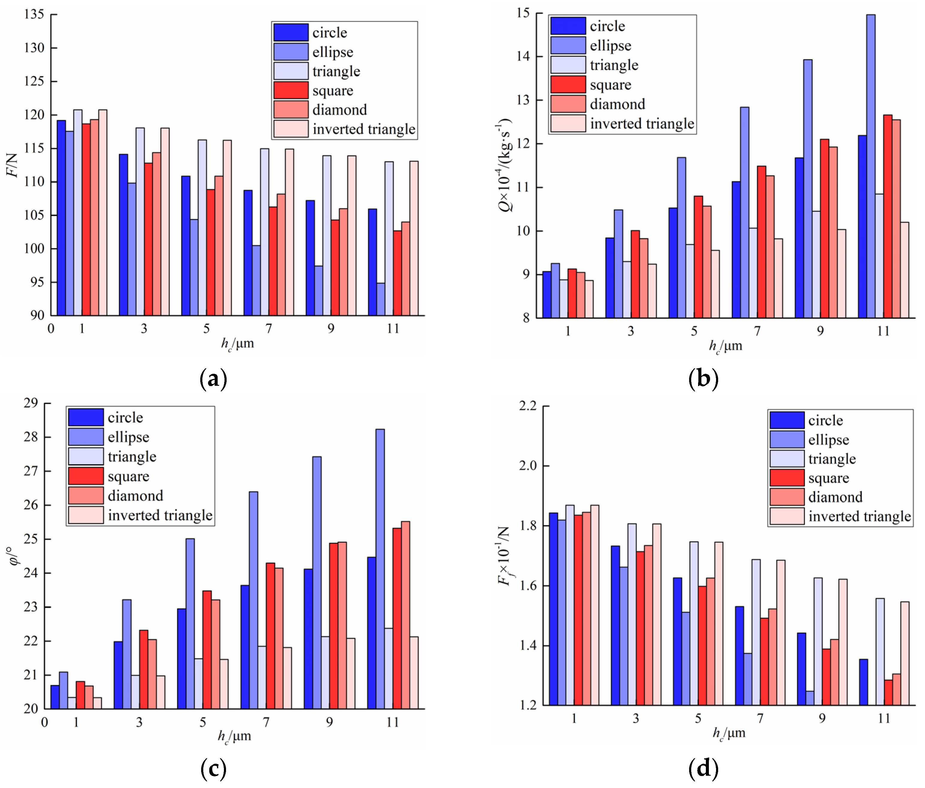
4.2. Analysis of the Static Characteristics

As can be seen from Figure 8a,b, with the linear increase in rotational speed, the gas dynamic pressure effect is enhanced and the gas film force increases significantly. However, the accelerated Couette flow does not have a significant effect on the flow in the axial direction. Hence, the mass leakage rate does not change with the change of rotational speed: the mass leakage rate of the elliptical texture is the largest and its value is maintained close to 9.87 × 10⁻⁴ kg·s−1. Figure 8c graphically shows the relationship between attitude angle and rotational speed. The attitude angles of the six texture types all show a decreasing trend as the rotational speed increases. A smaller attitude angle can make the operation of the sealing system more stable; thus, the higher the rotational speed, the better the stability of the compliant foil gas seal. Furthermore, it is found that when the rotational speed is 60,000 r·min−1, the minimum attitude angle of the triangular textures is 12.45°. In addition, as can be seen from the data in Figure 8d, when the rotational speed increases linearly, the viscous friction force also increases close to linearly because the speed gradient in the thickness direction of the gas film increases with the increase in rotational speed and the frequency of friction between the fluid layers.
As shown in Figure 9a,b, as texture depth increases, the gas film forces of the six textures all show a decreasing trend, and the mass leakages present a linear increasing trend. The gas film force and mass leakage rate of the elliptical texture change with the fastest speed, followed by the square texture. When hc < 5 μm, the gas film force and mass leakage of the circular texture exceed those of the diamond-shaped texture, whereas when hc ≥ 5 μm, the situation is reversed, which implies that when the depth of the textures increases, the diversion effect is disadvantageous because the effect of the increasing gas film thickness is more obvious in a low-pressure environment. When the texture depth varies from 1 to 11 μm, the gas film force of the inverted triangle and triangle are close and show the best ranking of the gas film force. However, the leakage rate of the triangle is not as good as that of the inverted triangle, and the difference is more obvious with the greater texture depth. This implies that the mass leakage rate is more sensitive to the divergence and convergence of the texture, and the fully divergent texture type is not conducive to reducing the mass leakage rate.
It can be seen from Figure 9c that as the texture depth increases, the attitude angle increases for different types of texture. The attitude angle of the elliptical texture is always larger than that of others, and the value of the inverted triangle is the smallest. The greater the texture depth, the more obvious the attitude angle difference of different textures is. When hc ≥ 9 μm, the attitude angle of the diamond-shaped texture exceeds that of the square texture, while the fluctuation of the inverted triangular texture tends to be gentle. It can be seen from Figure 9d that as texture depth increases, the viscous friction force of air film decreases. Compared with the other texture types, the elliptical texture has the largest cross-section and increasing the texture depth can rapidly increase the volume of the micro-pits, thereby considerably increasing the thickness of the gas film in the overall range. Thus, the viscous friction force of the elliptical texture is the most affected by the texture depth, i.e., it is reduced by 38.31%. By contrast, the viscous friction of the triangular texture is the least influence, i.e., it decreases by 16.66%.
Figure 9. (a) Description of force with depth; (b) Description of leakage with depth; (c) Description of attitude angle with depth; (d) Description of friction with depth.
Applsci 12 05633 g009

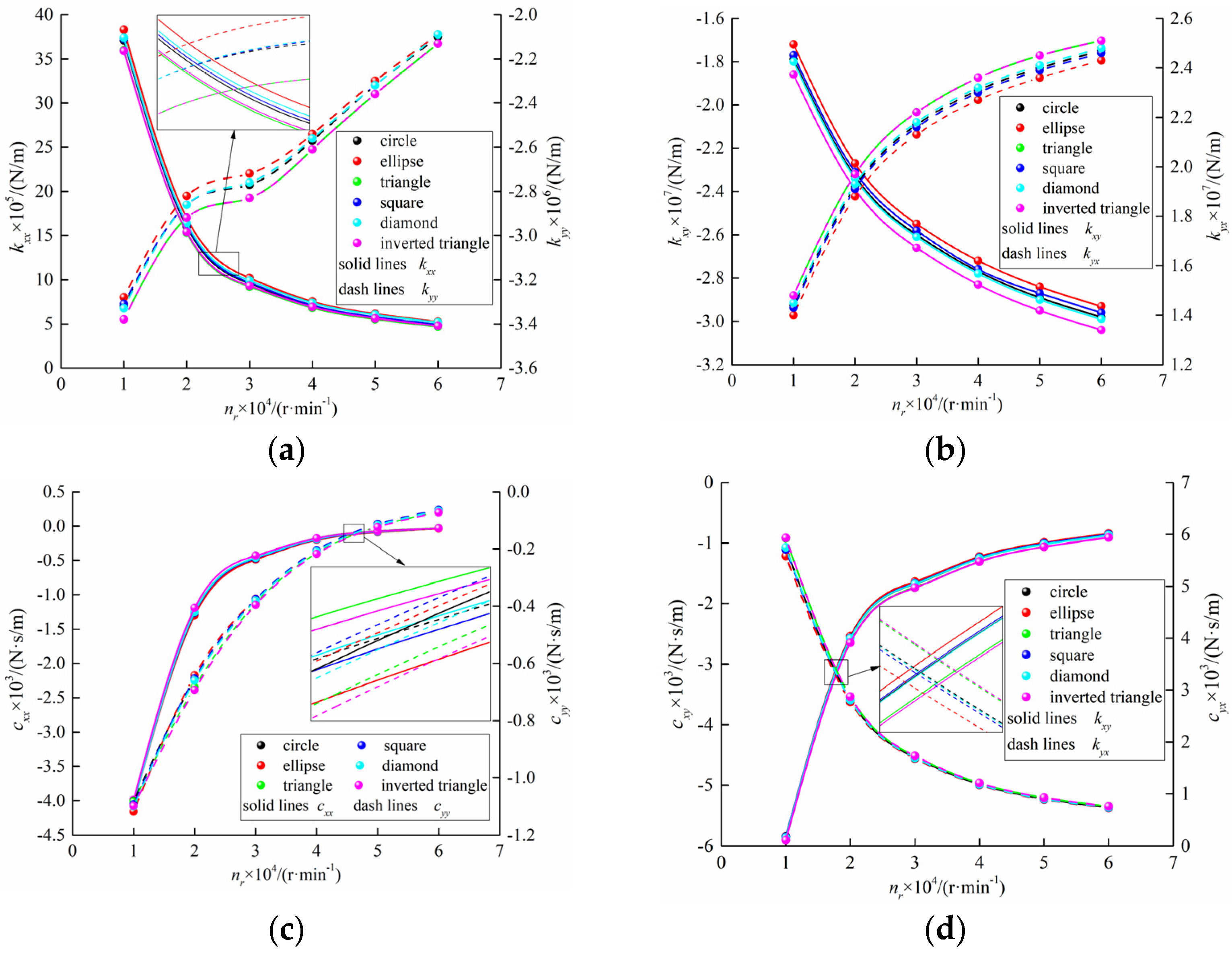
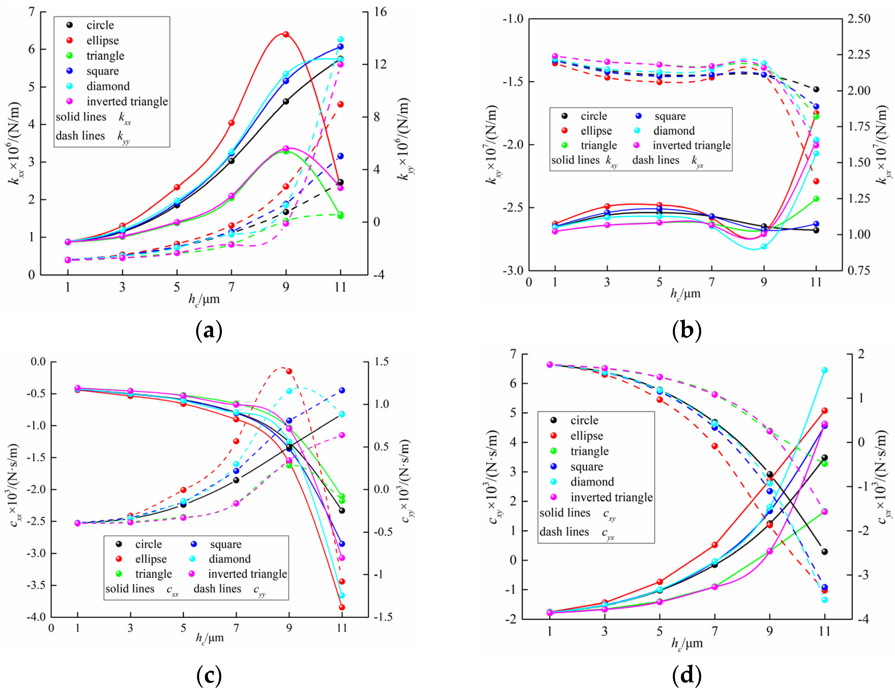
4.3. Analysis of the Dynamic Characteristics

Figure 10a,c show the variation of the direct dynamic coefficients with different rotational speeds. Specifically, kxx of the six texture types is positive and decreases as rotational speed increases, whereas kyy is negative and increases gradually. When the speed varies 10,000 and 20,000 r·min−1, the range of change of direct stiffness coefficient is large, however, it becomes smaller once the speed exceeds 30,000 r·min−1, which indicates that the direct stiffness coefficient is easily affected by the speed variation in the low-speed range and prone to instability. The changes in the direct damping coefficients have an approximate trend; as the speed increases, cxx and cyy monotonically increases from a negative value to a positive value. Regardless of the texture type, when the speed is less than 30,000 r·min−1, the rate of increase of cxx and cyy is higher. Once this speed is exceeded, the fluctuation of the direct damping gradually becomes smaller; it eventually remains flat, and the magnitude decreases to zero.
As can be seen from Figure 10b,d, the distributions of the cross dynamic characteristic coefficients are mutually symmetrical. As the speed increases, the sum of cross damping of the different texture types has different degrees of convergence, and the value keeps approaching zero, indicating that the cross damping does not need to dissipate more energy; thus, the speed increases to make the sealing system stable. As increasing the rotational speed in the low-speed range significantly improves the dynamic pressure effect, when the rotational speed exceeds a certain value, the dynamic pressure effect decreases, resulting in a larger difference in the cross-damping coefficients when the rotational speed is less than 30,000 r·min−1.
Figure 10. (a) Description of kxx and kyy with rotational speed; (b) Description of kxy and kyx with rotational speed; (c) Description of cxx and cyy with rotational speed; (d) Description of cxy and cyx with rotational speed.
Applsci 12 05633 g010
Figure 11 shows the influence of the texture depth on the dynamic characteristics. Owing to the change in the texture depth, the Couette flow and Poiseuille flows of the gas between the sealing interfaces are changed. The change in the fluid pressure distribution causes the changes in foil deformation; the thickness of the gas film changes accordingly, and the complexity of the flow field is enhanced. Therefore, when the texture depth changes, the dynamic characteristics fluctuate considerably. Figure 11a,b show the relationship between the stiffness coefficient and the texture depth for different texture types; kyy gradually increases with the increase of texture depth, and elliptical, triangular, and inverted triangular textures have the maximum positive kxx at hc = 9 μm, after which the value drops sharply. The distributions of kxy and kyx are still symmetrical. Except for the triangular texture, the sum of the cross stiffnesses of the others is basically stable.
From Figure 11b,c, when the texture depth increases, cxx of all textures decreases continuously. It is found by calculation that when the texture depth increases from 1 to 9 μm, the sum of direct damping shows an initially decreasing and subsequently increasing trend. According to the principle of energy, the difference of the cross stiffness has a positive impact on the vortex motion, whereas the sum of direct damping has a negative impact; therefore, the smaller the difference of the cross stiffness, and the greater the sum of the direct damping, the faster the convergence of the vortex motion, and the better the stability of the film. Thus, there is a high probability of instability when the texture depth exceeds 9 μm.
Figure 11. (a) Description of kxx and kyy with depth; (b) Description of kxy and kyx with depth. (c) Description of cxx and cyy with depth; (d) Description of cxy and cyx with depth.
Applsci 12 05633 g011

5. Discussion

Compliant foil gas seals are mainly applied under high-speed conditions. The theoretical model in this paper cannot take into account high-speed gas effects such as inertial effect, obstructed flow effect, and turbulent flow effect. Additionally, the coupling of multiple effects on the sealing properties of compliant foil gas seals cannot be characterized by this research. In the future, the above deficiencies need to be improved by revising the theoretical model, which is of great significance for accurately predicting the sealing performance of ultra-high-speed compliant foil gas seals.

6. Conclusions

In this paper, considering the specific structure of the compliant foil gas seal, as well as the stiffness and damping of the bump foil, the micro-scale dynamic lubrication equations of the synchronous circular motion of gas and the rotor in the cylindrical coordinate system are obtained. Then, the finite difference method and the iterative method are used to solve the thickness and deformation equations simultaneously, following which, the static and dynamic sealing characteristics corresponding to different micro-texture shapes are obtained. The analysis results are as follows:
(1)
Micro-textures machined on the surface of flat foil create local pressure rise regions within a stable flow field. Owing to the difference in the texture shape characteristics and directionality, the gas film thickness and pressure distribution of different compliant foil gas seals are different.
(2)
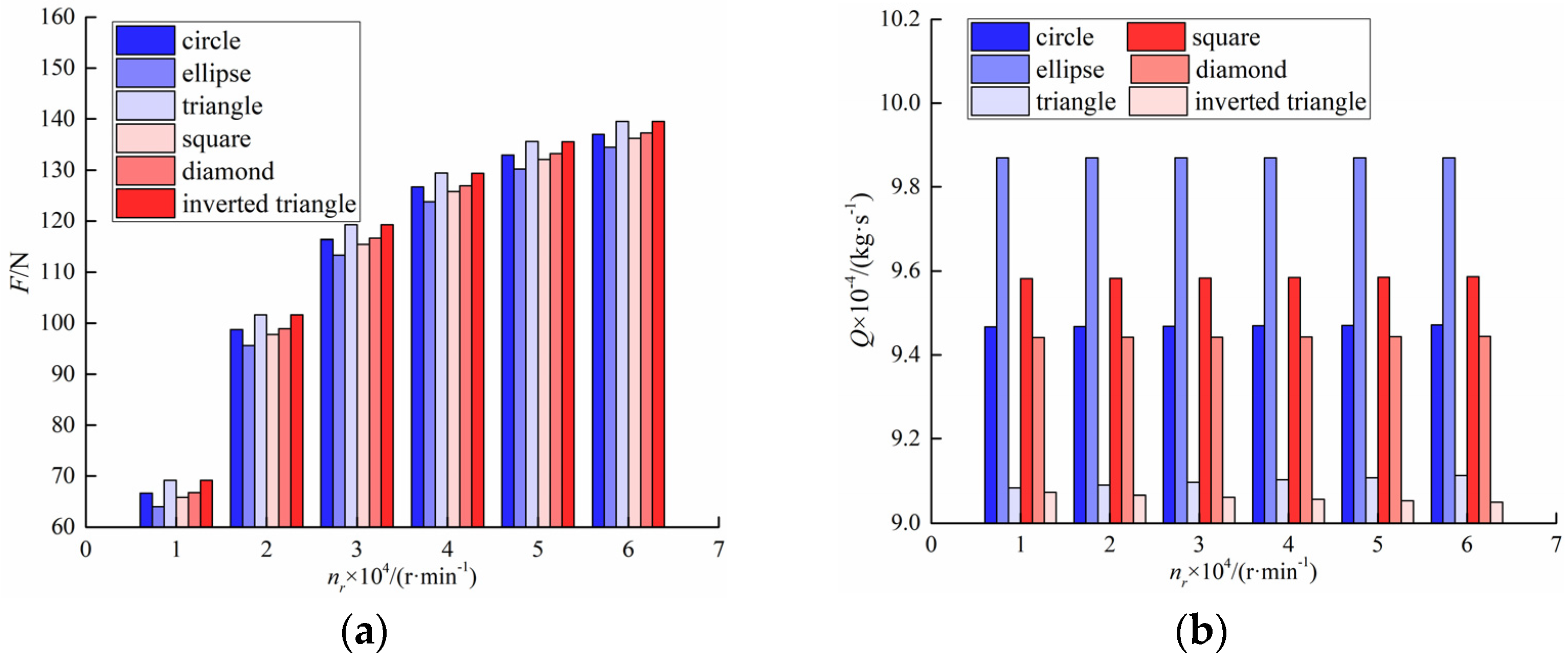
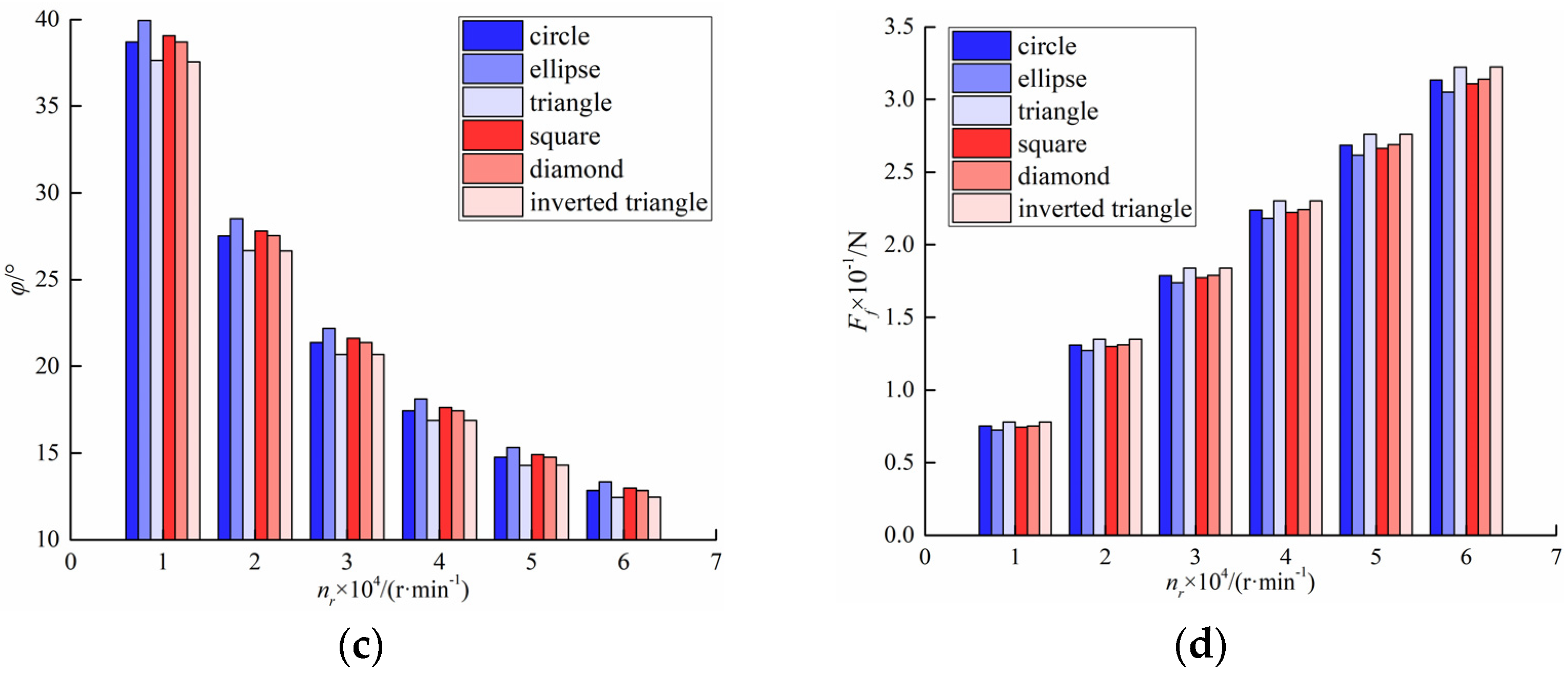
As the rotational speed increases, the force and the viscous friction force increase and the attitude angle decreases; however, the effect of the rotational speed on the mass leakage rate is negligible. Thus, the compliant foil gas seal shows good usability under low pressure and high-speed conditions.
(3)
Stiffness coefficients kxy and kyx and cross damping coefficients cxy and cyx are symmetrical. This reflects the circularity and quasi-symmetry of the flow field distribution as well as conform to the structural law of the compliant foil gas seal. Moreover, according to the dynamic parameters, the texture depth can be selected within the range of less than 9 μm to ensure stability.
(4)
Among the six typical texture shapes, the elliptical texture has the smallest gas film force and the largest mass leakage rate, which is the most unfavorable to the static sealing performance. The gas film force of the triangle and the inverted triangle are basically the same, but the inverted triangular texture can control the mass leakage rate and improve stability, thus showing the best comprehensive sealing performance.
This article selects the optimal shape and depth of micro-textures for compliant foil gas seals, and the results can guide the experimental testings and application of sealing surface modification. Furthermore, the image recognition technology used in this study provides implications for the complex interface design of friction pairs.

Author Contributions

Conceptualization, S.Y. and X.D.; methodology, J.X.; software, J.X.; validation, J.X. and L.L.; formal analysis, X.D.; investigation, H.J. and L.L.; resources, X.D.; data curation, J.X. and H.J.; writing—original draft preparation, J.X.; writing—review and editing, J.X.; visualization, H.J.; supervision, S.Y.; project administration, S.Y. and J.X.; funding acquisition, S.Y. and J.X. All authors have read and agreed to the published version of the manuscript.

Funding

This research was funded by Outstanding Postgraduate “Innovation Star” Project of Gansu Provincial Department of Education (grant no. 2021CXZX-459) and Major Scientific Research and Technological Innovation Project 2025, Ningbo (grant no. 2020Z112).

Institutional Review Board Statement

Not applicable.

Acknowledgments

The current research has been supported by Outstanding Postgraduate “Innovation Star” Project of Gansu Provincial Department of Education (grant no. 2021CXZX-459) and Major Scientific Research and Technological Innovation Project 2025, Ningbo (grant no. 2020Z112).

Conflicts of Interest

The authors declare no conflict of interest.

References

  1. Jiang, C.; Yin, C. Analysis on Aerodynamic Stability of Aero Gas Turbine Engine. Mech. Eng. Autom. 2021, 2, 182–184. [Google Scholar]
  2. Salehi, M.; Heshmat, H. On the Fluid Flow and Thermal Analysis of a Compliant Surface Foil Bearing and Seal. Tribol. Trans. 2000, 43, 318–324. [Google Scholar] [CrossRef]
  3. Lee, D.H.; Kim, Y.C.; Kim, K.W. The Effect of Coulomb Friction on the Static Performance of Foil Journal Bearings. Tribol. Int. 2010, 43, 1065–1072. [Google Scholar] [CrossRef]
  4. Song, J.H.; Kim, D.J. Foil Gas Bearing with Compression Springs: Analyses and Experiments. J. Tribol. 2007, 129, 628–639. [Google Scholar] [CrossRef]
  5. Wang, X.L.; Liu, M.H.; Sharon, K.W.; Hu, X.P. Numerical Evaluation of Rotor Dynamic Coefficients for Compliant Foil Gas Seal. Appl. Sci. 2020, 10, 9. [Google Scholar]
  6. Ma, G.; Xi, P.; Shen, X.M.; Hu, G.Y. Analysis of Quasi-dynamic Characteristics of Compliant Floating Ring Gas Cylinder Seal. J. Aerosp. Power 2010, 25, 1190–1196. [Google Scholar]
  7. Salehi, M.; Heshmat, H.; Walton, J. High Temperature Performance Evaluation of a Compliant Foil Seal. In Proceedings of the 36th AIAA/ASME/SAE/ASEE Joint Propulsion Conference & Exhibit, Huntsville, AL, USA, 17–19 July 2000. [Google Scholar]
  8. Salehi, M.; Heshmat, H. Performance of a Complaint Foil Seal in a Small Gas Turbine Engine Simulator Employing a Hybrid Foil/Ball Bearing Support System. Tribol. Trans. 2001, 44, 458–464. [Google Scholar] [CrossRef]
  9. Heshmat, H.; Walton, J. Innovative High-temperature Compliant Surface Foil Face Seal Development. In Proceedings of the 44th AIAA/ASME/SAE/ASEE Joint Propulsion Conference & Exhibit, Hartford, CT, USA, 21–23 July 2008. [Google Scholar]
  10. Salehi, M.; Heshmat, H. Analysis of a Compliant Gas Foil Seal with Turbulence Effects. In Proceedings of the 37th Joint Propulsion Conference and Exhibit, Salt Lake City, UT, USA, 8–11 July 2001. [Google Scholar]
  11. Kim, K.W.; Chung, J.T.; Kim, C.H.; Lee, Y.B. Theoretical Research of Static Characteristics of Bump Floating Ring Seal. J. Korean Soc. Tribol. Lubr. Eng. 2008, 24, 140–146. [Google Scholar]
  12. Lee, Y.B.; Kim, K.W.; Ryu, S.J. Leakage Performance and Rotordynamic Characteristics of Bump Floating Ring Seals for Turbopump. Am. Soc. Mech. Eng. 2014, 7B, 1–12. [Google Scholar]
  13. Ding, X.X.; He, Z.H.; Zhang, W.Z.; Lu, J.J.; Miao, C.H. Parameters Analysis of Steady Micro-scale Flow of Cylindrical Spiral Groove Dry Gas Seal. CIESC J. 2018, 69, 1537–1546. [Google Scholar]
  14. Wang, X.L.; Liu, M.H.; Xiong, Z.F.; Li, X. Turbulence Characteristics of Compliant Foil Gas Seal Considering Surface Roughness. CIESC J. 2022, 73, 1683–1694. [Google Scholar]
  15. Sahlin, F.; Glavatskih, S.B.; Almqvist, T.; Larsson, R. 2D CFD-Analysis of Micro-Patterned Surfaces in Hydrodynamic Lubrication. J. Tribol. 2004, 127, 1657–1665. [Google Scholar]
  16. Shi, L.; Wei, W.; Wang, T.; Zhang, Y.; Wang, X. Experimental Investigation of the Effect of Typical Surface Texture Patterns on Mechanical Seal Performance. J. Braz. Soc. Mech. Sci. Eng. 2020, 42, 227. [Google Scholar] [CrossRef]
  17. Stull, F.; Velkoff, H. Effects of Transverse Ribs on Pressure Recovery in Two-dimensional Subsonic Diffusers. In Proceedings of the Joint Propulsion Specialist Conference, Columbus, OH, USA, 29 November 1972. [Google Scholar]
  18. Mariotti, A.; Buresti, G.; Salvetti, M.V. Separation Delay through Contoured Transverse Grooves on a 2D Boat-tailed Bluff Body: Effects on Drag Reduction and Wake Flow Features. Eur. J. Mech.—B/Fluids 2018, 74, 351–362. [Google Scholar] [CrossRef]
  19. Liu, K.; Liu, Z.; Khan, A.M.; Chen, L.; Zhao, M. Effects of the Inclination Angles of DLC End Face Micro-texture on the Tribological Properties of Dry Gas Seal Rings. Surf. Topogr. Metrol. Prop. 2021, 9, 045014. [Google Scholar] [CrossRef]
  20. Chen, J.L.; Tang, L.P.; Ding, X.X.; Si, J.X.; Chen, D.L.; Sun, B.C. Frictional Vibration Performances of Dry Gas Seal Rings with DLC Film Textured Surface via Chaos Theory. Tribol. Trans. 2021, 64, 667–678. [Google Scholar] [CrossRef]
  21. Senatore, A.; Risitano, G.; Scappaticci, L.; D’Andrea, D. Investigation of the Tribological Properties of Different Textured Lead Bronze Coatings under Severe Load Conditions. Lubricants 2021, 9, 34. [Google Scholar] [CrossRef]
  22. Lang, A.W.; Jones, E.M.; Afroz, F. Separation Control over a Grooved Surface Inspired by Dolphin Skin. Bioinspiration Biomim. 2017, 12, 026005. [Google Scholar] [CrossRef]
  23. Bai, L.Q.; Zhang, P.C.; Khan, Z.A. Semi Salix Leaf Textured Gas Mechanical Face Seal with Enhanced Opening Performance. Materials 2021, 14, 7522. [Google Scholar] [CrossRef]
  24. Wu, Z.; Bao, H.; Xing, Y.Q.; Liu, L. Tribological Characteristics and Advanced Processing Methods of Textured Surfaces: A Review. Int. J. Adv. Manuf. Technol. 2021, 114, 1241–1277. [Google Scholar] [CrossRef]
  25. Ma, G.; Yang, W.R. Numerical Simulation and Parameter Optimization of Seal Property of Bidirectional Rotating Cylinder Gas Film. J. Beijing Univ. Aeronaut. Astronaut. 2016, 42, 2279–2288. [Google Scholar]
  26. Wang, T.; Liu, M.H.; Sun, J.F.; Dai, D. Simulation Analysis of the Sealing Performance of Cylinder Gas Film. Fluid Mach. 2020, 48, 55–60. [Google Scholar]
  27. Lu, J.J.; Zhang, W.; Ma, H. Floating Performance of Cylindrical Microgroove Gas Floating Seal Based on F-K Slip Flow Model. CIESC J. 2021, 72, 4267–4278. [Google Scholar]
  28. Iordanoff, I. Analysis of an Aerodynamic Compliant Foil Thrust Bearing: Method for a Rapid Design. ASME J. Tribol. 1999, 121, 816–822. [Google Scholar] [CrossRef]
  29. Chen, T.; Liu, M.H. Effects of Operating Parameters on the Seal Performance of Cylindrical Gas Film. Fluid Mach. 2014, 42, 43–46. [Google Scholar]
Figure 1. (a) Schematic of the compliant foil gas seal. (b) Mechanisms for the lubricating gas film formation.
Applsci 12 05633 g001
Figure 2. (a) Deformation of the foil. (b) Structural parameters of the bump foil.
Applsci 12 05633 g002
Figure 3. Distribution of the micro-textures.
Applsci 12 05633 g003
Figure 4. Calculation flow chart.
Applsci 12 05633 g004
Figure 5. Computational program verification [29].
Applsci 12 05633 g005
Figure 8. (a) Description of force with rotational speed. (b) Description of leakage with rotational speed. (c) Description of attitude angle with rotational speed. (d) Description of friction with rotational speed.
Applsci 12 05633 g008aApplsci 12 05633 g008b
Table 1. Geometric structure and mechanical performance parameters.
ParametersValuesParametersValuesParametersValues
R (mm)25a (mm)2rb (mm)3.365
L (mm)26.67b (mm)3α (°)63.93
Nt16tb (mm)0.2016vb0.3
h0 (μm)10l (mm)1.778Eb (Pa)2.14 × 10¹¹
hc (μm)2s (mm)4.572
Table 2. Operating parameters.
ParametersValuesParametersValuesParametersValues
pi (MPa)0.16μf0.1ρ (kg·m−3)1.1425
po (MPa)0.101325nr (r·min−1)30,000μ (Pa·s)1.8 × 10⁻⁵
Publisher’s Note: MDPI stays neutral with regard to jurisdictional claims in published maps and institutional affiliations.

