Abstract
Two specimens of low-yield-point steel plate shear walls used for the experimental investigation into different failure modes of the structure were respectively carried out by the horizontal and vertical loading tests in this paper. The results derived from the horizontal loading test for specimen 1 demonstrated that both the infill panel and the frame column were seriously damaged as the loading level increased with continuous and steady strain growth, in which maximum out-of-plane displacement and strain of the infill panel reached 31.8 mm and 11,735 με respectively, whereas the strain of the frame column reached 13,117 με. Moreover, the structural bearing capacity decreased extremely slowly and the specimen still had a high strength when the controlled displacement of the specimen exceeded 3.28 times the yield displacement, which indicated that the ductility of the structure was excellent. The results of a vertical loading experiment for specimen 2 indicated that the maximum deformation of both the infill panel and frame column occurred in the middle-upper part of the members, with a maximum out-of-plane displacement of 95 mm and 70 mm, respectively. The dramatic out-of-plane bulging phenomenon along the width of the infill plate under the vertical load and the seriously torsional deformation of the frame column were observed.
1. Introduction
Steel plate shear wall (SPSW) structure was a new type of lateral force resisting structural system when it was developed in the 1970s. Steel plate shear walls, consisting of embedded steel plates, vertical edge members (columns), and horizontal edge members (beams), have been adopted as one of the lateral load resisting systems in high-intensity seismic areas for the past 40 years. The excellent performance of steel plate shear walls in improving structural bearing capacity, stiffness, ductility, and energy dissipation capacity led to the widespread application of this system and different academic scholars have conducted experimental studies [,,] and abundant simulation research [,,,] on steel plate shear walls, which was tremendously applied in engineering practice [,,].
Various seismic structures and energy dissipation materials, such as foamed aluminum [,] and low-yield-point steel [], which replaced the traditional reinforced concrete construction [,,,], have been discovered and utilized as scholars continued their research on seismic performance. Low-yield-point (LYP) steel, as a new material with better inelastic deformation capacity, superior elongation, and low yield-strength ratio, has been increasingly utilized and developed in energy dissipation and vibration damping structures such as steel plate shear walls and dampers [,,]. The low-yield-point steel exhibits 2 to 3 times the elongation of ordinary structural steel, possesses a lower yield-strength ratio, and has significant strain hardening characteristics in the post-yield phase. Therefore, low-yield-point steel plate shear walls have high ductility and energy dissipation capacity to meet the developing requirements of high-rise steel structures. Most of the domestic and international investigations on steel plate shear walls made of ordinary steel in the past 30 years were divided into two diverse sorts according to the different design methods, which include the prevention of infill panel buckling for thick plates and utilization of strength after buckling for thin plates, while a relatively few investigations were focused on low-yield-point SPSW []. Therefore, research on structural characteristics including the failure modes and seismic performance of LYP SPSW under horizontal low cyclic loads and vertical loads will be helpful to fill this deficiency.
The LYP SPSW structural system consists of an infill panel made of low-yield-point steel and an external frame [,], which possesses the lower yielding characteristic and higher buckling capacity of the infill panel, and prominent lateral resisting stiffness and excellent ductility performance of an overall system [,,]. The low-yield-point steel appears to have extremely low-yield strength, which could dissipate the abundant seismic energy by plastic deformation earlier under the action of an earthquake [,,,,]. The internal wall panel that behaved just like a “fuse” in buildings will significantly yield and dissipate energy before the external frame when subjected to the numerous lateral forces, which is extremely beneficial to guarantee the safety of the overall structure and satisfied the design principle of multiple seismic defense lines for a double lateral force-resisting system.
At present, almost all the research about the low-yield-point steel plate shear walls has been focused on or restricted to the investigation into seismic performance under horizontal loads, rather than vertical loads. However, the whole steel elements in the SPSW structure were inevitably subjected to vertical loads such as dead load, live load, snow load, etc., in practical service conditions. In addition, even if the steel plate shear wall was under horizontal loads, the column would undergo a certain compression deformation, which apparently causes the vertical deformation of the steel plate connected to the column, resulting in compressive stresses within the infill panel. The influence induced by the vertical load on the shear bearing capacity should be seriously considered when the SPSW as the energy absorption and lateral resisting element is applied in the seismic area. This disadvantageous deformation caused by the vertical load could not consequently be neglected for the calculation of structural stability.
According to the above valuable references, the LYP steel plate shear wall structure is a new type of seismic energy dissipation system with superior energy dissipation capacity. In this system, LYP steel is used for shear wall panels, while conventional structural steel is adopted for boundary frames. Taking advantage of its high energy dissipation and easy replacement can improve the seismic performance of new buildings and existing buildings. Meanwhile, in order to prevent the structure from out-of-plane deformation that may affect the test to some extent, a novel torsional lateral steel bracing system is designed to make the test results as accurate as possible. Based on this device, horizontal cyclic loading tests and vertical loading tests of single-span single-story LYP steel plate shear wall structures were conducted in the structural engineering laboratory, respectively. The test results of two different load types for this new structural system will be helpful to guide the seismic design of LYP SPSW structures in practical engineering applications.
2. Horizontal Cyclic Loading Test
2.1. Test Scheme
2.1.1. Design of Specimen 1
Because low-yield-point steel belongs to a new type of structural material and the current market demand is not extensive, only a few thickness specifications of steel plate can be selected and purchased. Therefore, the shear infill panels used for the loading experiment of the LYP steel plate shear wall in this paper were adopted as 8 mm thickness with a yield strength of 100 MPa. The rest of the members in the specimen were made of Q235 steel with a yield strength of 235 MPa. The ultimate bearing capacity was limited to 800 kN in the design of the specimen, taking into account the loading equipment. Therefore, the section size of each member in the reduced scale specimens of the LYP SPSW structure designed according to the shear bearing capacity of the infill panel was determined as shown in Table 1.

Table 1.
The section size of two specimens (units: mm).
In order to ensure that the superstructure of specimen 1 withstood the horizontal load as a whole, this specimen was rigidly connected at the bottom by high-strength bolts to a 60 mm thick steel plate, which was rigidly connected to the laboratory floor using anchor bolts to provide rigid restraint support for this specimen. The frame beam with a section size of H150 × 150 × 7 × 10 mm was located at the upper part of specimen 1, whereas frame columns with a section size of H125 × 125 × 6.5 × 9 mm were at the left and right sides. The loading connection device was designed at one end of the frame beam and was connected to the loading end of the horizontal loading actuator MTS so as to implement the horizontal load on the specimen. The shear infill panel, frame beam, and frame columns in the specimen were connected by welding with the basic form of the weld section being a fillet weld and the distribution of the weld being a perimeter weld. The design details for the drawing of specimen 1 are shown in Figure 1, Figure 2, Figure 3 and Figure 4.
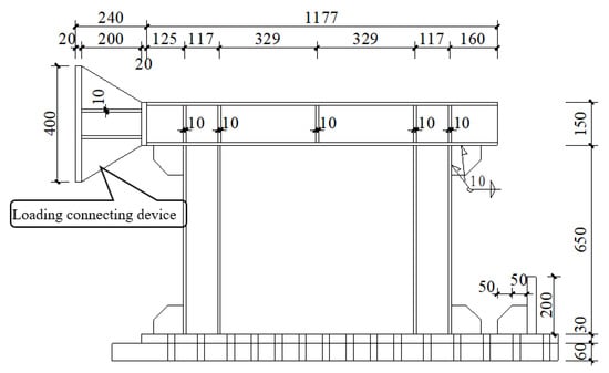
Figure 1.
Elevation of specimen 1 (units: mm).
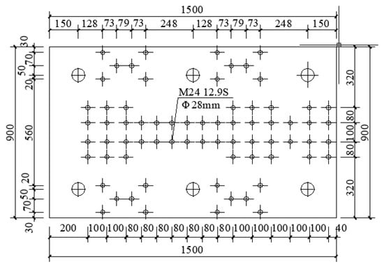
Figure 2.
Detailed drawing of 60 mm thick large bottom plate (units: mm).
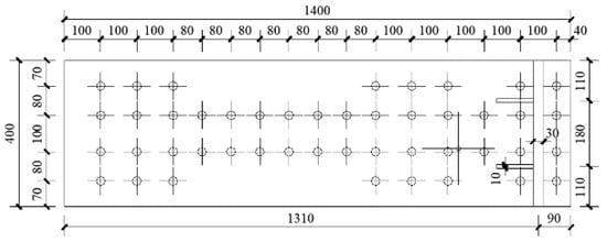
Figure 3.
Detailed drawing of 30 mm thick small bottom plate (units: mm).
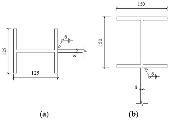
Figure 4.
Connection of infill panel in specimen 1 (units: mm): (a) Welding connection between column and infill panel; (b) Welding connection between infill panel and beam.
For the specimen 1 under the horizontal low cyclic load, the seismic performance of the LYP SPSW in this specimen was obtained by utilizing the reaction wall and the horizontal loading actuator MTS in the structural engineering laboratory, and the top beam was connected to the actuator through the loading connection device on this specimen. A set of brackets was designed at the front and rear of the shear infill panel to control the apparent out-of-plane torsional deformation of the shear infill panel during the loading process and to guarantee that the specimen remained in the horizontal direction when loaded with horizontal load and to ensure the accuracy of the test data.
2.1.2. Material Property Test
The uniaxial tensile test on steel coupons were carried out to obtain fundamental mechanical properties of the materials, including the yield strength, ultimate tensile strength, modulus of elasticity, elongation, and yield ratios. The typical steel coupons designed in the shape of the plate shown in Figure 5 for the material tensile test were cut from the base metals. Table 2 presents the detailed sizes of different geometric parameters of the coupons, and three tensile coupons were tested for the LYP steel with the nominal yield strength of 100 MPa.
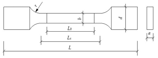
Figure 5.
Fabricated coupon.

Table 2.
Size of the coupon (units: mm).
These three steel coupons for tensile tests were respectively installed on the electro-hydraulic universal material-testing machine, which can automatically record the maximum load, yield strength, and ultimate strength at the end of the test (Figure 6). The tensile coupons of LYP steel were observed to stretch considerably long, from the initial elasticity to the yield and then to the strain hardening stage until the necking fracture. The cross-sectional area was reduced to a sufficiently small section, and the fractured surface was uneven and jagged after the tensile fracture of LYP steel coupons, as shown in Figure 7, which indicates that this LYP steel exhibits superior ductile performance.
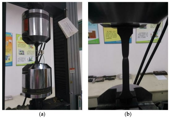
Figure 6.
Material tensile test: (a) Installation; (b) Fracture.
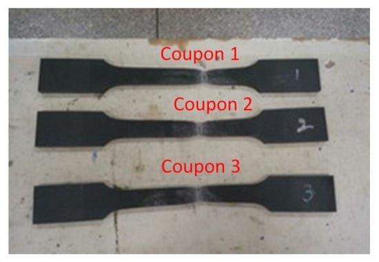
Figure 7.
Fabricated LYP steel coupons.
Table 3 presents the different mechanical behaviors of low-yield-point and ordinary steel specimens under quasi-static tensile tests. In comparison, the ratios of yield strength, ultimate tensile strength, and yield ratio of LYP steel to Q235 steel were approximately 0.41, 0.64, and 0.63, respectively, whereas the elongation of LYP steel was approximately 1.36 times that of Q235 steel. The actual engineering stress-strain curves of LYP steel could then be calculated and achieved based on the test results, as shown in Figure 8.

Table 3.
Results of the material test.

Figure 8.
Stress-strain curves of the LYP steel.
2.1.3. Experimental Device
It was necessary to determine the section size of the 60 mm thick steel plate in the specimen and the location of bolt holes depending on the position of foundation anchor holes on the laboratory floor just before conducting the horizontal low cyclic loading test on the specimen 1. There were six foundation anchor bolts of φ60 at the bottom for the specimen so as to make the superstructure of specimen 1 as a whole withstanding the horizontal load and jointly bearing the applied force, and the location of holes for the steel plate at the bottom of the specimen is shown in Figure 9.
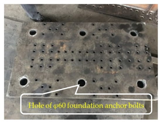
Figure 9.
60 mm thick connecting plate.
In order to ensure that the loading connection device in specimen 1 could effectively transfer load subjected to the action of a larger load, some stiffener plates were respectively welded to the loading head of the connecting device and the upper flange of frame beam, which provided reinforcement to the loading device.
It was important to stabilize the 60 mm thick connecting plate in the specimen so as to avoid significant slippage during the test loading. A stiffening baffle was welded to the end of the connecting plate in this specimen and jacked against the stiffening baffle. The reinforcement diagram of specimen 1 is shown in Figure 10.
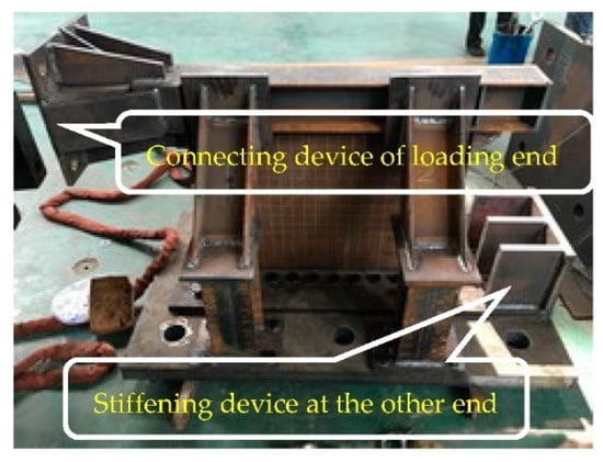
Figure 10.
Detailed drawing of reinforcement for specimen 1.
2.1.4. Loading Scheme
A quasi-static test scheme was utilized for specimen 1 and a horizontal low cyclic load was imposed on the specimen with a mixed force-displacement loading regime. The loading process of specimen 1 was divided into 14 load levels, and the first five levels were loaded by force, with control loads of 50 kN, 100 kN, 200 kN, 250 kN and 300 kN respectively. The actuator displacement control was adopted from the sixth level, and the controlled displacement was measured as the percentage of top displacement to the height of specimen, which were 0.65% (5 mm), 0.77% (6 mm), 0.9% (7 mm), 1.16% (9 mm), 1.55% (12 mm), 1.94% (15 mm), 2.32% (18 mm), 2.71% (21 mm) and 3.1% (24 mm). The horizontal cyclic loading regime of specimen 1 is shown in Figure 11. The specimen was preloaded as well as checked for proper operation of the whole test before the horizontal loading was formally exerted.
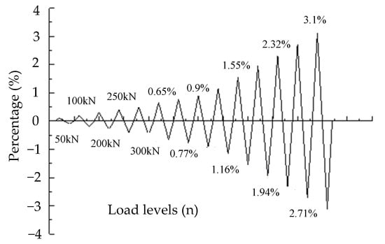
Figure 11.
Horizontal cyclic loading regime of specimen 1.
In order to better observe the out-of-plane deformation phenomenon of the infill panel, the numerous grid lines on one side of the infill panel were drawn, as shown in Figure 12.
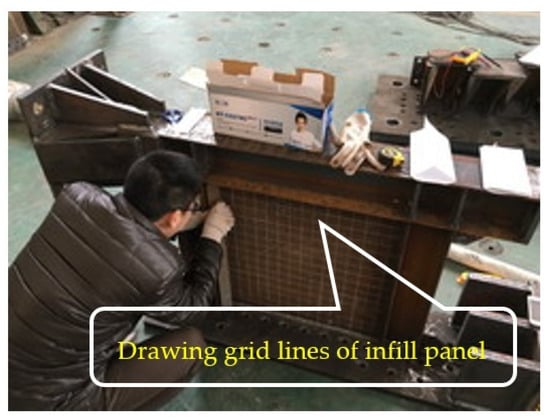
Figure 12.
Drawing grid lines of infill panel for specimen 1.
2.2. Experimental Results
2.2.1. Description of Failure Phenomenon
A horizontal low cyclic load was executed on specimen 1. The loading process in this direction was called forward loading when the actuator was pushed against specimen 1, and the structure produced a displacement of more than zero, whereas the opposite operation was called reverse loading and the structure generated a displacement of less than zero.
The forward loading displacement was measured to be 0.17 mm and the reverse loading displacement was also 0.17 mm upon being loaded to the first level load of 50 kN without apparent phenomenon in the loading process of the structure. The frame columns and the LYP infill panel yielded no visible out-of-plane displacement. The displacement of forward loading was 0.48 mm, whereas the displacement of reverse loading was 0.46 mm when the second stage load was 100kN with an out-of-plane displacement of 0.08 mm at the center for the infill panel. The displacement returned to zero when the loading was returned to zero, which showed that the structure was in the elastic stage at that moment. The forward loading displacement was estimated to be 1.3 mm and the reverse loading displacement was 1.1mm at the third load level of 200 kN. A slight sound emerged during the loading process and the maximum out-of-plane displacement of the center for the infill panel was 0.1 mm. The forward loading displacement was detected as 1.8 mm and the reverse loading displacement was 1.5 mm for the fourth level of 250 kN; however, the structure remained in an elastic state. At the fifth load level of 300 kN, the forward loading displacement was 2.4 mm and the reverse loading displacement was 1.8 mm. Moreover, the infill panel started to enter the yielding state with the maximum out-of-plane displacement of 0.14 mm. It was found that the hysteresis curve of the structure occurred in an obvious non-linear phase by observing the force-displacement records in the main control room, and hence the loading regime of the actuator was adjusted from force control to displacement control for the subsequent loading levels. Measured displacements under the first five loading levels are shown in Table 4.

Table 4.
Measured displacements under the first five loading levels.
At the sixth loading level, the maximum reaction force of the actuator forward loading was 320.8 kN and the displacement was 2.9 mm, whereas the reverse loading was 398.2 kN and the displacement was 2.7 mm. Four slight sounds appeared during the loading process and there was no significant variation in the shape of the structure (Figure 13). The frame column was not yielded, whereas all four corners of the infill panel started to enter the yielding state and the shear panel had the maximum out-of-plane displacement of 0.17 mm at the center.
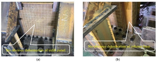
Figure 13.
Deformation at the sixth loading level: (a) Infill panel; (b) Column base.
The maximum reaction force of the actuator forward loading was 385.3 kN during the seventh loading stage and the displacement measured from the displacement meter was 3.7 mm, while the maximum reaction force of the reverse loading was 462.1 kN and the displacement was 3.0 mm. A slight sound from the structure was accompanied by the loading process, and the middle-upper part of the infill panel gradually entered the yielding stage, at which time the maximum out-of-plane displacement at the center of infill panel was 0.22 mm.
At the eighth loading level, the maximum reaction force of the actuator forward loading was 423.5 kN with a displacement of 4.3 mm, while that for reverse loading was 530.4 kN with a displacement of 3.5 mm. The sound was significantly enlarged in the loading process and the frame column was still not yielded with the maximum out-of-plane displacement of 0.24 mm at the center of the infill plate.
At the time of the ninth loading level, the maximum reaction force for the actuator forward loading was 537.2 kN with a displacement of 5.3 mm, and that for the reverse loading was 617.3 kN with a displacement of 4.0 mm. There was a continuous muffled sound during the loading process and the middle-lower part of the infill panel started to enter the yielding state, at which time the maximum out-of-plane displacement for the infill panel center was 0.3 mm.
When the tenth level was loaded, the maximum reaction force of actuator forward loading was 650.6 kN and the displacement was 6.9 mm, whereas reverse loading was 689.9 kN and the displacement was 5.9 mm. The left flange at the left column base was the pioneer in yielding and the maximum out-of-plane displacement at the center of the shear panel was 0.5 mm. The foundation anchor bolts on the bottom of the structure that were utilized to limit the slip of the bottom plate emerged significantly loose.
The forward maximum force was 716.0 kN with a displacement of 8.1 mm, while the reverse maximum load was 751.3 kN with a displacement of 8.5 mm during the eleventh loading level. The right flange of the left column foot appeared yielding and the continuous brittle sound appeared during the loading process. Moreover, the floating rust at the column web was obviously observed to fall off and the infill panel appeared to be slightly convex. The maximum out-of-plane displacement at the center of shear panel was 3.7 mm. The deformation of the structure is shown in Figure 14.
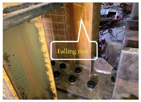
Figure 14.
Falling rust at the web of column.
At the twelfth loading level, the maximum reaction force of actuator forward loading was 740.8 kN with the measured displacement of 10.5 mm, and that of reverse loading was 753.9 kN with the displacement of 11.2 mm. The loading process was accompanied by a continuous giant sound and the maximum out-of-plane displacement at the center of the infill panel was 18.4mm, which indicated that the deformation was more conspicuous compared with the previous loading levels. Meanwhile, there was prominent peeling rust and tensile texture at the web of top beam. The deformation of the member is shown in Figure 15.
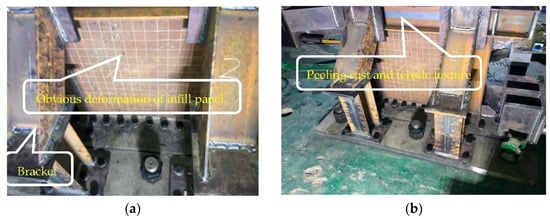
Figure 15.
Deformation of the infill panel and top beam for specimen 1: (a) Infill panel; (b) Top beam.
At the thirteenth loading level, the maximum forward force of the actuator was 370.2 kN whose displacement was 10.5 mm, whereas reverse loading was 765.5 kN and displacement was 11.4 mm. The flanges of the column foot on both sides were in the yielding state and a continuous sharp brittle sound was observed during the loading procedure. The forward loading displacement was up to 16.9 mm and the overall bearing capacity of the structure obviously degraded, which was caused by the further expansion of the deformation for the infill panel and the bulging of the upper flange for the top beam at one end of the loading head. Meanwhile, the steel plate connected with the loading head deformed in buckling as a result of the thin plate thickness. By now the maximum out-of-plane displacement of the infill panel reached 25.7 mm and the deformation of different members was indicated in Figure 16, respectively.
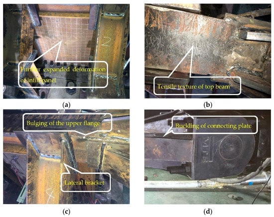
Figure 16.
Deformation of structural members for specimen 1: (a) Infill panel; (b) Top beam; (c) Upper flange on the top beam; (d) Connecting plate.
The forward reaction force of the actuator was 685.4 kN and the corresponding displacement was 10.5 mm, whereas the reverse loading was 775.3 kN and displacement was 16.9 mm at the fourteenth loading level. The structural bearing capacity dropped dramatically at the end of this loading and no more load was applied to the specimen through the actuator. Meanwhile, the horizontal low cyclic loading test on specimen 1 was terminated. Eventually, the infill panel appeared to severely bulge and the weld between infill panel and frame column occurred to be cracked, which induced a maximum out-of-plane displacement of 31.8 mm at the center of the infill panel. The deformation of the member after the termination of the test was shown in Figure 17.
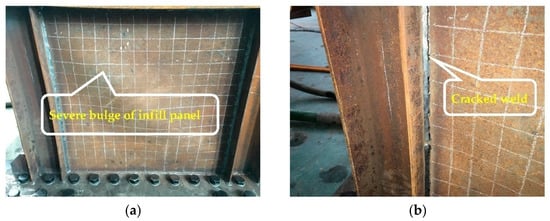
Figure 17.
Structural deformation of specimen 1 after the termination of the experiment: (a) Infill panel; (b) Weld between infill panel and frame column.
2.2.2. Change in Bearing Capacity after Yielding
For the purpose of reflecting the rapidity of the bearing capacity variation after the overall yielding for specimen 1 under horizontal low cyclic loading, two dimensionless quantities, F/Fy and Δ/Δy, can be established. The F was the horizontal load at the peak point of the first cycle at each load level after yielding, whereas the Δ was the top displacement corresponding to F. Fy and Δy were the yielding loads and yielding displacement of the structure as a whole, respectively.
The relationship curves between F/Fy and Δ/Δy after yielding of the specimen are shown in Figure 18. The bearing capacity after yielding was on the ascending trend, whereas, when the structure was loaded in the forward direction with the top displacement Δ of 1.74Δy, the bearing capacity began to descend due to the excessive bulging of the infill panel and the compressive buckling of the upper flange of top beam at the loading end. The bearing capacity curve after yielding kept rising under reverse loading of the structure, which was attributed to the extraordinary strain-hardening characteristics of LYP steel that would merely produce relatively large plastic deformation without cracking failure in the loading process. The structural bearing capacity was still 1.17Fy when the post-yield top displacement Δ reached 3.28Δy under reverse loading, which illustrated that the structure remained remarkably high-strength even when the post-yield displacement was loaded to a larger multiple of the yield displacement, further indicating that the LYP SPSW possessed outstanding structural ductility.
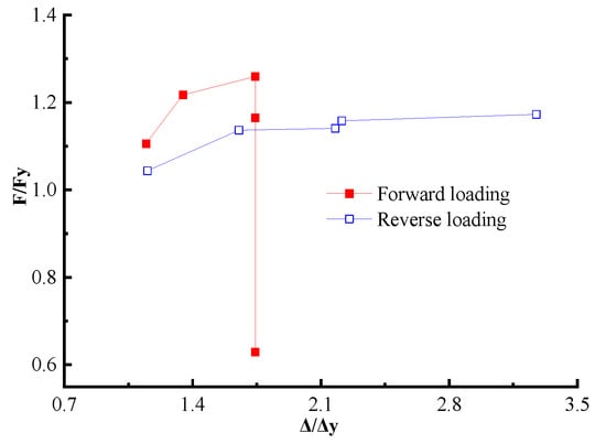
Figure 18.
Change in bearing capacity after yielding for specimen 1.
2.2.3. Strain
Three-dimensional strain rosettes were arranged at its corners and center to investigate the shear characteristic of infill panel. The strain gauges were fixed on the flange of column at the top, middle, and bottom locations to obtain the tensile or compressive performance of frame columns. The distribution of strain gauges is shown in Figure 19.
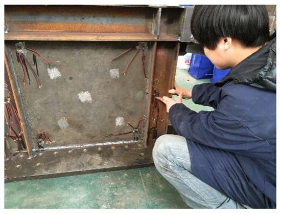
Figure 19.
Strain gauge arrangement in specimen 1.
Due to the damage of a few strain gauges and collection channels, those strain gauges that were along the 45° direction at the three corners of infill panel, at the middle location of infill panel, along the 45° direction at the middle and lower part of left column web, and at the lower part of left column flange were extracted and analyzed to derive their alterations with increasing load. Table 5 summarizes the strain values at different locations for the specimen at each level of peak load.

Table 5.
Strain values at different locations for specimen 1 at each level of peak load(units: με).
The yielding strain value of the infill panel, beam, and column can be calculated according to Equation (1):
A low-yield-point infill panel was adopted as the steel of LYP100 with a nominal yield strength of 100 MPa and the measured yielding strain derived from the material test was as follows in Equation (2):
Q235 steel with a nominal yield strength of 235 MPa was used for frame beams and columns, and the corresponding measured yielding strain was the following in Equation (3):
The variations of strain with the number of loading levels during forward and reverse loading for the infill panel are shown in Figure 20. It can be observed from the figure that the measured strain values of infill panel developed relatively smoothly before the eleventh loading level, whereas those strain values developed extremely rapidly when the eleventh loading level was reached, which was consistent with the observed suddenly increasing trend of the out-of-plane deformation of infill panel. The strain increasing development in the upper-right corner and lower-left corner of the infill panel was identical in the process of forward and reverse loading, and was more rapid than that in other positions, which was due to the deformation of the infill panel towards one side in the last few loading levels. The strain variation of infill panel was larger in the reverse loading than in the forward loading, which was attributed to the fact that the forward loading had failed at the thirteenth load level and the bearing capacity decreased, while the structural bearing capacity was invariably increasing in the reverse loading.
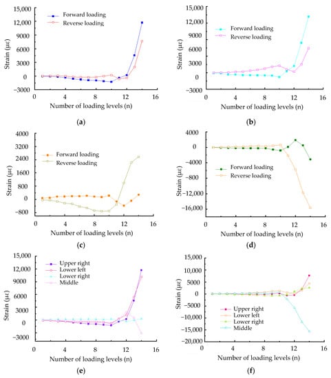
Figure 20.
Variations of strains in the infill panel of specimen 1: (a) Strains at the upper-right corner of infill panel; (b) Strains at the lower-left corner of infill panel; (c) Strains at the lower-right corner of infill panel; (d) Strains at the middle of infill panel; (e) Strains of infill panel during forwarding loading; (f) Strains of infill panel during reverse loading.
The variations of strain with the number of loading levels for the left column during forward and reverse loading are shown in Figure 21. It can be seen from the diagram that the strain values in the middle and lower part of the web for the left column had similar development trends under forward and reverse loading, and developed toward one side after the eleventh loading level with significantly increased development speed. The strain value of the right flange increases with the number of load stages and the change accelerates after the eleventh stage. The trends of strains at the left flange developed in opposite directions at different loading modes. The measured strains in the frame column were larger for reverse loading than those for forward loading in the last few levels.
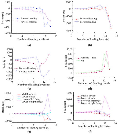
Figure 21.
Variations of strains in the left column of specimen 1: (a) Strains at the middle of web; (b) Strains at the lower part of web; (c) Strains at the lower part of left flange; (d) Strains at the lower part of right flange; (e) Strains during forwarding loading; (f) Strains during reverse loading.
2.2.4. First Principal Stress Inclination of Wall Panel
The angle α between the first principal stress of the wall panel and the horizontal direction can be calculated by utilizing the measured strain values derived from the three-dimensional strain rosettes at the four corners of shear panel, which is deduced by Equation (4) and Table 6.

Table 6.
Calculation formula of strain in the direction of strain rosette.
The inclination angle of the first principal stress at each part in the shear wall panel during forward and reverse loading is shown in Figure 22. The angle variation with the number of loading levels is shown in Table 7. As can be seen from the figure, the inclination angle of the first principal stress at the same part under the forward loading was larger than that under the reverse loading. The development trend of the first principal stress inclinations was generally consistent under the forward and reverse loading, which is gradually increasing at the first 3 levels, remaining flat or decreasing from 4 to 12 levels, and finally progressively expanding. It can be seen from the table that, on the whole, the inclination angle of the first principal stress for the shear panel in the specimen varies from 8° to 45°.
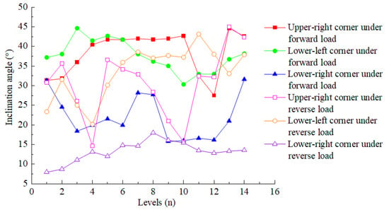
Figure 22.
Variation of the inclination angle of the first principal stress in the wall panel.

Table 7.
The inclination angle of the first principal stress at each part of wall panel under the forward and reverse loading test (units: °).
3. Vertical Loading Test
3.1. Test Scheme
3.1.1. Design of Specimen 2
The vertical loading test was conducted in accordance with the similar principle of the above horizontal reciprocal loading test to develop the model size. The low-yield-point steel with a nominal yield strength of 100 MPa was used for the shear wall in specimen 2, whereas Q355 steel was adopted for the rest of the members. The section size of each member in the test specimen is shown in Table 8.

Table 8.
The section size of specimen 2 (units: mm).
To guarantee that the superstructure of the specimen 2 as a whole was subjected to vertical load, specimen 2 was rigidly connected to a 60 mm thick steel plate at the bottom through high-strength bolts, and the plate was also rigidly connected to the horizontal loading test trolley by utilizing high-strength bolts to provide rigid restraint support for the specimen 2. The frame columns with a section size of H150 × 150 × 7 × 10 mm were located at both the left and right sides of specimen 2, while a steel plate with a section size of 1800 × 450 × 60 mm was installed at the upper part, and another steel plate of the same size was applied at the bottom. The upper steel plate was rigidly connected to the actuator of the vertical loading device by a special screw, which was designed to furnish a similar rigid crossbeam in the SPSW structure. The shear infill panel, upper and bottom steel plates, and frame columns in this specimen were connected in the same welding connection as specimen 1. The design details for the drawing of specimen 2 are shown in Figure 23, Figure 24, Figure 25 and Figure 26.
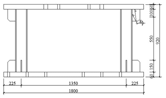
Figure 23.
Elevation of specimen 2 (units: mm).
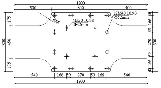
Figure 24.
Detailed drawing of the 60 mm thick upper plate of specimen 2 (units: mm).

Figure 25.
Detailed drawing of the 60 mm thick bottom connecting plate of specimen 2 (units: mm).
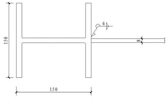
Figure 26.
Connection of the infill panel with frame column in specimen 2 (units: mm).
With the aim of executing the vertical loading experiment on specimen 2, a compression-shear machine in the structural engineering laboratory was utilized to impose a vertical load on this specimen for evaluating the deformation characteristics of the LYP SPSW structure. An integrated set of brackets at the position of the frame column for specimen 2 was elaborately designed to control the numerous deformations of the frame column, which could guarantee the movement of this specimen along the vertical direction when loaded with vertical load, reducing the impact caused by the deformation of the frame column on the shear infill panel and preventing the overall out-of-plane displacement of the member.
3.1.2. Experimental Device
Before the vertical loading test was conducted on specimen 2, it was necessary to identify the section size of the 60 mm thick bottom connection plate on the specimen in accordance with the size of the test trolley for vertical loading equipment, and then the bottom connection plate was rigidly connected with the test trolley through high-strength bolts to make these two components become a whole and jointly undergo the vertical loading. The roof plate of specimen 2 possessed a large bending stiffness to guarantee that the vertical loading from the actuator could be uniformly transferred to the LYP shear infill panel through the roof plate during the loading process. The installed loading test device for specimen 2 is shown in Figure 27 and Figure 28.
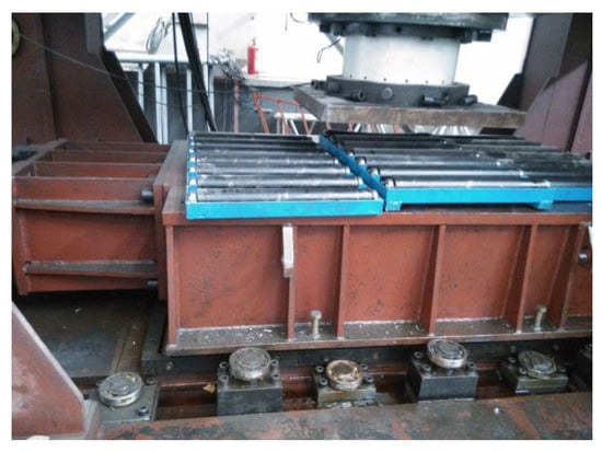
Figure 27.
Vertical loading device of specimen 2.
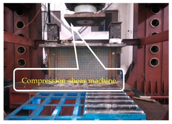
Figure 28.
Detailed drawing of installed loading test device for specimen 2.
3.1.3. Loading Scheme
The deformation characteristics of the LYP SPSW structure were evaluated by applying a vertical loading to specimen 2 with a compression-shear machine, which was regarded as an exploratory research test for this structure since few experimental investigations on SPSW structure were conducted by the vertical loading. The grid lines were drawn on one side of the infill plate to monitor the out-of-plane deformation phenomenon in the infill plate.
3.2. Experimental Results
Description of Failure Phenomenon
The vertical loading test was investigated solely for its deformation characteristics owing to many conditions such as time and site constraints. A vertical load was imposed on specimen 2 until the structure was broken with a final reaction force of 3800 kN. The vertical deformation of the specimen after being loaded along the vertical direction by the compression-shear machine is shown in Figure 29, and the compression amount of the specimen along the width direction is shown in Figure 30. The bottom connecting plate of the specimen was not significantly deformed because of the sufficient rigidity for the trolley surface and the deformation of the specimen was primarily concentrated in the upper top plate. The deformation of the upper top plate was mainly focused on the middle of the specimen because the brackets on both sides restricted the vertical displacement of the overhanging part for the upper top plate.
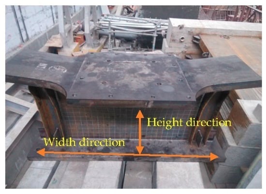
Figure 29.
Vertical deformation of specimen 2.
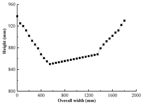
Figure 30.
The overall compression amount of specimen 2 along the width direction.
The vertical deformation of the shear infill panel is shown in Figure 31. The out-of-plane displacement of infill panel along the width direction, and the height corresponding to the maximum out-of-plane displacement as well as the deformation at the middle part of infill panel are shown in Figure 32. It can be seen from the figure that the maximum out-of-plane displacement of the infill panel emerged in the middle and upper part, which showed out-of-plane bulging in the width direction with the maximum out-of-plane deformation of 95 mm at the center of the infill panel.
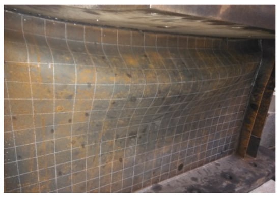
Figure 31.
Vertical deformation of infill panel in specimen 2.
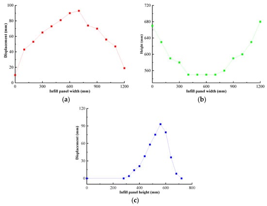
Figure 32.
Deformation diagram of the infill panel for specimen 2: (a) Out-of-plane displacement in the width direction; (b) Height at the maximum displacement; (c) Deformation at the middle part of infill panel.
Under the action of vertical loading, the deformation mode of the column flange is shown in Figure 33 and the out-of-plane displacement distribution of the column flange along the height direction is shown in Figure 34. As indicated by the figure, the large out-of-plane deformation of the column flange was mainly focused on the upper part and torsional deformation occurred in the frame column. The deformation at the bottom of the specimen was considerably less than that at the upper part as the structure was directly subjected to the vertical load. Moreover, the maximum out-of-plane displacement of the column flange was 70 mm.
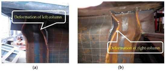
Figure 33.
Deformation of column flange for specimen 2: (a) Left column flange; (b) Right column flange.
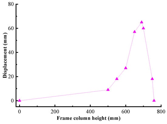
Figure 34.
Out-of-plane deformation of the column flange along the height in specimen 2.
4. Conclusions
The LYP SPSW is a novel kind of lateral force resisting system with excellent development potential. Two reduced scale specimens of single-story single-span LYP steel plate shear wall were fabricated to investigate the seismic performance and deformation characteristic of the LYP SPSW structure with consideration of various loading factors. The horizontal low cyclic loading test was executed for specimen 1, whereas the vertical loading experiment was implemented for specimen 2.
Through the horizontal cyclic loading test of the low-yield-point steel plate shear wall, the study focused on the failure phenomenon of this structure, the change in bearing capacity after yielding, the strain variation, and the inclination angle of the first principal stress of the wall panel, so as to make a reasonable evaluation of the seismic performance for the specimen. In addition, the deformation characteristics of the LYP SPSW structure were evaluated by applying vertical loading to specimen 2 with a compression-shear machine, which was regarded as an exploratory research test for this structure since few experimental investigations on SPSW structure have been conducted by vertical loading. The different failure phenomena and performance of this structure under the two different loading actions were analyzed in detail from various perspectives. The detailed contents and major observations were as follows.
- (1)
- Specimen 1 was loaded with a mixed force-displacement system. The infill panel entered the yielding state at the end of the first five loading levels with the maximum out-of-plane displacement of 0.14 mm, and then the infill panel started to appear with a slight bulge at the eleventh loading level and the maximum out-of-plane displacement of 3.7 mm. The infill panel severely bulged and the column base was significantly distorted up to the fourteenth loading level. The maximum out-of-plane displacement at the center of the infill panel reached 31.8 mm.
- (2)
- Specimen 1 was further loaded by applying the controlled displacement that increased from 1.74 to 3.28 times the yield displacement after yielding. The structural bearing capacity decreased extremely slowly and the specimen still possessed a relatively high strength, which indicated that the ductility of this structure was excellent.
- (3)
- The overall strains of the infill panel and frame columns continued to grow smoothly with the increasing forward and reverse loading levels. The increasing rate of strain developed rapidly until the fourteenth loading level, and the measured maximum strains respectively reached 11,735 με for the infill plate and 13,117 με for the frame column, which was significantly higher than the yielding strains of 470.4 με and 1174 με derived from the material tests of LYP steel and ordinary Q235 steel.
- (4)
- The results obtained by the vertical loading experiment for specimen 2 indicated that the maximum deformation of both infill panel and frame columns occurred at the middle-upper part of members. The dramatic out-of-plane bulging phenomenon developed along the width of the infill plate under the vertical load, whereas the seriously torsional deformation occurred at the frame column. The maximum out-of-plane deformations were 95 mm at the center of the infill panel and 70 mm at the flange of the frame column, respectively.
- (5)
- The inclination angle of the first principal stress in the wall panel was analyzed, and in overall terms, the inclination angle of the shear panel varied from 8° to 45°.
Author Contributions
Writing—review and editing, Q.L.; visualization, Q.L.; conceptualization, J.S.; validation, J.S.; investigation, J.S.; supervision, J.S.; methodology, B.T.; validation, B.T.; investigation, B.T.; data curation, B.T.; writing—original draft, B.T.; resources, Z.W. All authors have read and agreed to the published version of the manuscript.
Funding
This research was funded by the Science and Technology Program of Guizhou Province, grant number [2019]1288; Postgraduate Research & Practice Innovation Program of Jiangsu Province, grant number KYCX21_3495; Jiangsu Overseas Visiting Scholar Program for University Prominent Young and Middle-Aged Teachers and Presidents, grant number 2018169; and National Natural Science Foundation of China, grant number 51308260. However, any opinions, findings, conclusions, and recommendations presented in this paper are those of the writers and do not necessarily reflect the views of the sponsors.
Institutional Review Board Statement
Not applicable.
Informed Consent Statement
Informed consent was obtained from all subjects involved in the study.
Data Availability Statement
Not applicable.
Conflicts of Interest
The authors declare that they have no known competing financial interests or personal relationships that could have appeared to influence the work reported in this paper.
References
- Bypour, M.; Kioumarsi, M.; Yekrangnia, M. Shear capacity prediction of stiffened steel plate shear walls (SSPSW) with openings using response surface method. Eng. Struct. 2021, 226, 111340. [Google Scholar] [CrossRef]
- Bypour, M.; Kioumarsi, B.; Kioumarsi, M. Investigation of Failure Mechanism of Thin Steel Plate Shear Wall in RC Frame. Key Eng. Mater. 2019, 803, 314–321. [Google Scholar] [CrossRef]
- Bypour, M.; Gholhaki, M.; Kioumarsi, M.; Kiousmarsi, B. Nonlinear analysis to investigate effect of connection type on behavior of steel plate shear wall in RC frame. Eng. Struct. 2019, 179, 611–624. [Google Scholar] [CrossRef]
- Moammer, O.; Deylami, A.; Jafari, K.; Raisszadeh, A.H. Numerical investigation of influence of plate yield point on performance of steel plate shear wall. Ce/Papers 2017, 1, 3165–3172. [Google Scholar] [CrossRef]
- Munesi, A.; Gholhaki, M.; Sharbatdar, M. Numerical study on seismic behaviour of buckling-restrained steel plate shear walls. Proc.Inst. Civ. Eng. Struct. Build. 2021. [Google Scholar] [CrossRef]
- Hamed, A.A.; Asl, R.B.; Rahimzadeh, H. Experimental and numerical study on the structural performance of auxetic-shaped, ring-shaped and unstiffened steel plate shear walls. J. Build. Eng. 2021, 34, 101939. [Google Scholar] [CrossRef]
- Mu, Z.G.; Yang, Y.Q. Experimental and numerical study on seismic behavior of obliquely stiffened steel plate shear walls with openings. Thin-Walled Struct. 2020, 146, 106457. [Google Scholar] [CrossRef]
- Paslar, N.; Farzampour, A.; Hatami, F. Infill plate interconnection effects on the structural behavior of steel plate shear walls. Thin-Walled Struct. 2020, 149, 106621. [Google Scholar] [CrossRef]
- Meghdadaian, M.; Ghalehnovi, M. Improving seismic performance of composite steel plate shear walls containing openings. J. Build. Eng. 2019, 21, 336–342. [Google Scholar] [CrossRef]
- Xu, T.; Shao, J.H.; Zhang, J.Y.; Kaewunruen, S. Experimental Performance Evaluation of Multi-Storey Steel Plate Shear Walls Designed by Different Methods. Int. J. Civ. Eng. 2019, 17, 1145–1154. [Google Scholar] [CrossRef]
- Wang, T.T.; Shao, J.H.; Xu, T.; Wang, Z.G. Study on Axial Compression Properties of Aluminum Foam-filled Steel Tube Members after High Temperature. Iran. J. Sci. Technol. Trans. Civ. Eng. 2022, 46, 883–900. [Google Scholar] [CrossRef]
- Wang, Z.G.; Wang, Y.; Pan, C.R.; Li, J. Research on the Torsional Properties of Aluminum Foam-filled Steel Tube after Fire. J. Asian Archit. Build. Eng. 2018, 17, 525–531. [Google Scholar] [CrossRef]
- Shao, J.H.; Wang, K.; Kaewunruen, S.; Cai, W.H.; Wang, Z.G. Experimental Investigations into Earthquake Resistance of Steel Frame Retrofitted by Low-Yield-Point Steel Energy Absorbers. Appl. Sci. 2019, 9, 3299. [Google Scholar] [CrossRef]
- Mou, B.; Li, Y.Z.; Qiao, Q.Y. Connection behavior of CFST column-to-beam joint implanted by steel rebars under cyclic loading. Eng. Struct. 2021, 246, 113036. [Google Scholar] [CrossRef]
- Wang, T.T.; Shao, J.H.; Zhao, C.; Liu, W.J.; Wang, Z.G. Shaking Table Test for Evaluating the Seismic Performance of Steel Frame Retrofitted by Buckling-Restrained Braces. Shock. Vib. 2021, 2021, 6654201. [Google Scholar] [CrossRef]
- Mou, B.; Zhou, W.Q.; Qiao, Q.Y.; Feng, P.; Wu, C.L. Column base joint made with ultrahigh-strength steel bars and steel tubular: An experimental study. Eng. Struct. 2021, 228, 111483. [Google Scholar] [CrossRef]
- Mou, B.; Liu, X.; Sun, Z. Seismic behavior of a novel beam to reinforced concrete-filled steel tube column joint. J. Constr. Steel Res. 2021, 187, 106931. [Google Scholar] [CrossRef]
- Abebe, D.Y.; Jeong, S.J.; Getahune, B.M.; Segu, D.Z.; Choi, J.H. Hysteretic characteristics of shear panel damper made of low yield point steel. Mater. Res. Innov. 2015, 19, S5–S902. [Google Scholar] [CrossRef]
- Abebe, D.Y.; Choi, J.H.; Jeong, S.J. Effect of Width-to-Thickness Ratio on Large Deformation in Shear Panel Hysteresis Damper Using Low Yield Point Steel. Appl. Mech. Mater. 2013, 446–447, 1460–1465. [Google Scholar] [CrossRef]
- Abebe, D.Y. Analytical Study on Large Deformation in Shear Panel Hysteresis Damper Using low-yield-point Steel. In Proceedings of the 2013 NZSEE Conference, Wellington, New Zealand, 26 April 2013; Graduate School of Architectural Engineering, University of Chosun: Gwangju, Korea, 2013. [Google Scholar]
- Jebelli, H.; Mofid, M. Effects of using low yield point steel in steel plate shear walls. IES J. Part A Civ. Struct. Eng. 2014, 7, 51–56. [Google Scholar] [CrossRef]
- Shahi, N.; Adibrad, M.H. Finite-element analysis of steel shear walls with low-yield-point steel web plates. Proc. Inst. Civ. Eng. Struct. Build. 2018, 171, 326–337. [Google Scholar] [CrossRef]
- Togo, T.; HE, L.S.; Hayashi, K.; Kurata, M.; Nakashima, M. Seismic behavior and design of assembled slit shear walls using low-yield-point steel. J. Struct. Constr. Eng. (Trans. AIJ) 2016, 81, 335–343. [Google Scholar] [CrossRef][Green Version]
- Bahrebar, M.; Lim, J.B.P.; Clifton, G.C.; Zirakian, T.; Shahmohammadi, A.; Hajsadeghi, M. Response assessment and prediction of low yield point steel plate shear walls with curved corrugated web plates and reduced beam sections. Structures 2020, 28, 1729–1745. [Google Scholar] [CrossRef]
- He, L.S.; Togo, T.; Hayashi, K.; Kurata, M.; Nakashima, M. Cyclic Behavior of Multirow Slit Shear Walls Made from Low-Yield-Point Steel. J. Struct. Eng. 2016, 142, 4016094. [Google Scholar] [CrossRef]
- Zirakian, T.; Zhang, J. Structural performance of unstiffened low yield point steel plate shear walls. J. Constr. Steel Res. 2015, 112, 40–53. [Google Scholar] [CrossRef]
- Shariati, M.; Faegh, S.S.; Mehrabi, P.; Bahavarnia, S.; Zandi, Y.; Masoom, D.R.; Toghroli, A.; Trung, N.T.; Salih, M.N.A. Numerical study on the structural performance of corrugated low yield point steel plate shear walls with circular openings. Steel Compos. Struct. 2019, 33, 569–581. [Google Scholar] [CrossRef]
- Zirakian, T.; Zhang, J. Seismic design and behavior of low yield point steel plate shear walls. Int. J. Steel Struct. 2015, 15, 135–151. [Google Scholar] [CrossRef]
- Khoeilar, A.R.; Zirakian, T.; Boyajian, D.; Maalouf, S.; Dermendjian, N. Case Study on Retrofit of Steel Plate Shear Walls Using low-yield-point Steel Infill Plates. J. Steel Struct. Constr. 2016, 2, 1–6. [Google Scholar] [CrossRef]
- Azandariani, M.G.; Gholhaki, M.; Kafi, M.A. Experimental and numerical investigation of low-yield-strength (LYS) steel plate shear walls under cyclic loading. Eng. Struct. 2020, 203, 109866. [Google Scholar] [CrossRef]
- Wang, M.; Zhang, X.K.; Yang, L.; Yang, W.G. Cyclic performance for low-yield point steel plate shear walls with diagonal T-shaped-stiffener. J. Constr. Steel Res. 2020, 171, 106163. [Google Scholar] [CrossRef]
Publisher’s Note: MDPI stays neutral with regard to jurisdictional claims in published maps and institutional affiliations. |
© 2022 by the authors. Licensee MDPI, Basel, Switzerland. This article is an open access article distributed under the terms and conditions of the Creative Commons Attribution (CC BY) license (https://creativecommons.org/licenses/by/4.0/).


