1. Introduction
Recent hardware-oriented improvements and possibilities enabled the application of machine learning in many different projects aimed at simplifying work or the daily life of people with disabilities. An example of such an application is the estimation of head orientation, based on video input, to control mouse position on the screen [
1], which could be beneficial for people with limb disabilities.
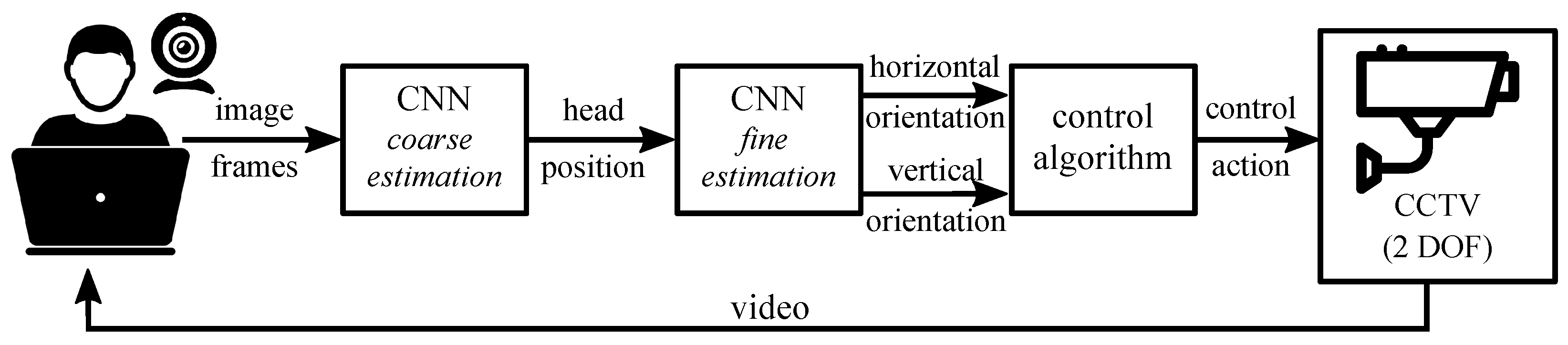
The scope of this work lies within the mainstream convention. In this work, a fully automatic solution was proposed to control the orientation of closed-circuit television (CCTV) simply by movements of the operator’s head. The main motivation behind the proposed solution is to allow people with disabilities to control the surveillance system without the need to use their hands. The schematic representation of the proposed solution is presented in
Figure 1.
The main problem tackled in this work is to combine the video-based head orientation information and the control signals of servomechanisms. Several aspects have to be named here. First, to enable the use of head orientation estimators in a control loop, a processing time should be limited far below the current state-of-the-art. Second, the chosen set of estimation classes should be reasonable to reflect the intention of the user. Therefore, a trade-off should be made between the number of output classes and the estimation time. Third, the proper correspondence between the estimation classes and the generated control signal should be defined.
The presented solution consists of a web camera focused on the operator’s face, a processing unit, and a camera mounted on a two degrees of freedom (DOF) mount controlled by two separate drives. The video recorded on the operator’s side is evaluated online, and the corresponding head orientation class is estimated. An important aspect of the design stage was to keep the operator fatigue level as low as possible. Therefore, an assumption is made that an unintended motion of the operator’s head would not result in the movement of the CCTV camera.
The head orientation class is fed to the control algorithm of two drives that move the CCTV mounting. The operator has visual feedback from the surveillance camera and can modify its orientation online by moving the head. In particular, the proposed solution is designed for a 2DOF mounting system but can be easily expanded to more degrees of freedom.
The head orientation estimator is based on Convolutional Neural Networks (CNN) and consists of several steps. First, the head position is detected on each image frame, together with its bounding box (denoted as a
coarse estimation in
Figure 1). Second, the cropped head images are evaluated in terms of head orientation. Two separate CNNs are used to this end for vertical and horizontal orientations. The main assumption of this part of the work was to train CNN using face images of different quality. It is assumed that the final application works properly for videos acquired by typical web cameras with different resolutions. Therefore, a new dataset was collected, acquired by different smartphones and different non-professional individuals.
The main contribution of this work is three-fold. First, a fast algorithm for estimating head orientation that incorporates CNNs for surveillance applications was proposed. A comparative analysis of the performance of our solution and its alternatives was performed. The presented algorithm provided a seven-times faster estimation. Second, the presented proposition was able to estimate the head orientation from image data where the person’s gaze direction does not correspond to the head pose. It remains a challenging problem, as the estimation of head orientation is strongly related to the direction of gaze [
2]. Third, a control signal generator was established, the values of which depend solely on the estimated head orientation.
2. Materials and Methods
This project was carried out in a few stages. First, the output and input data were defined to accurately reflect the problem addressed. The comprehensive dataset of images was collected by non-professionals and preprocessed. This part of the work is described in
Section 2.1.
In the second stage, described in
Section 2.2, the collection of CNNs was trained and tested (please refer to
Figure 1). The coarse-to-fine manner of both CNNs causes the accumulation of estimation errors. Therefore, solid validation was conducted on each of the networks separately, as well as on both CNNs working in series. This part of the work is presented in
Section 3.
The head orientation class is used to determine the control action for CCTV camera mounting drives.
Section 2.3 presents the hardware used in this study. To ensure the real-time operation of the system, fast and wireless communication was created between the components. This part of the work is described in
Section 2.4.
2.1. Dataset Preparation
In this scenario, the operator had to always have eye contact with the screen for surveillance reasons. The data used for training should incorporate this information. This feature limits the usage of publicly available datasets. Usually, the head orientation is variable with an inline gaze, or the head orientation is constant, and the gaze is responsible for the desired action (e.g., mouse movement). In this project, none of the above applies. The gaze is pointed in the direction of a computer screen, whereas movements of the head should dictate the desired action. Due to the unique character of this problem, a new dataset was collected.
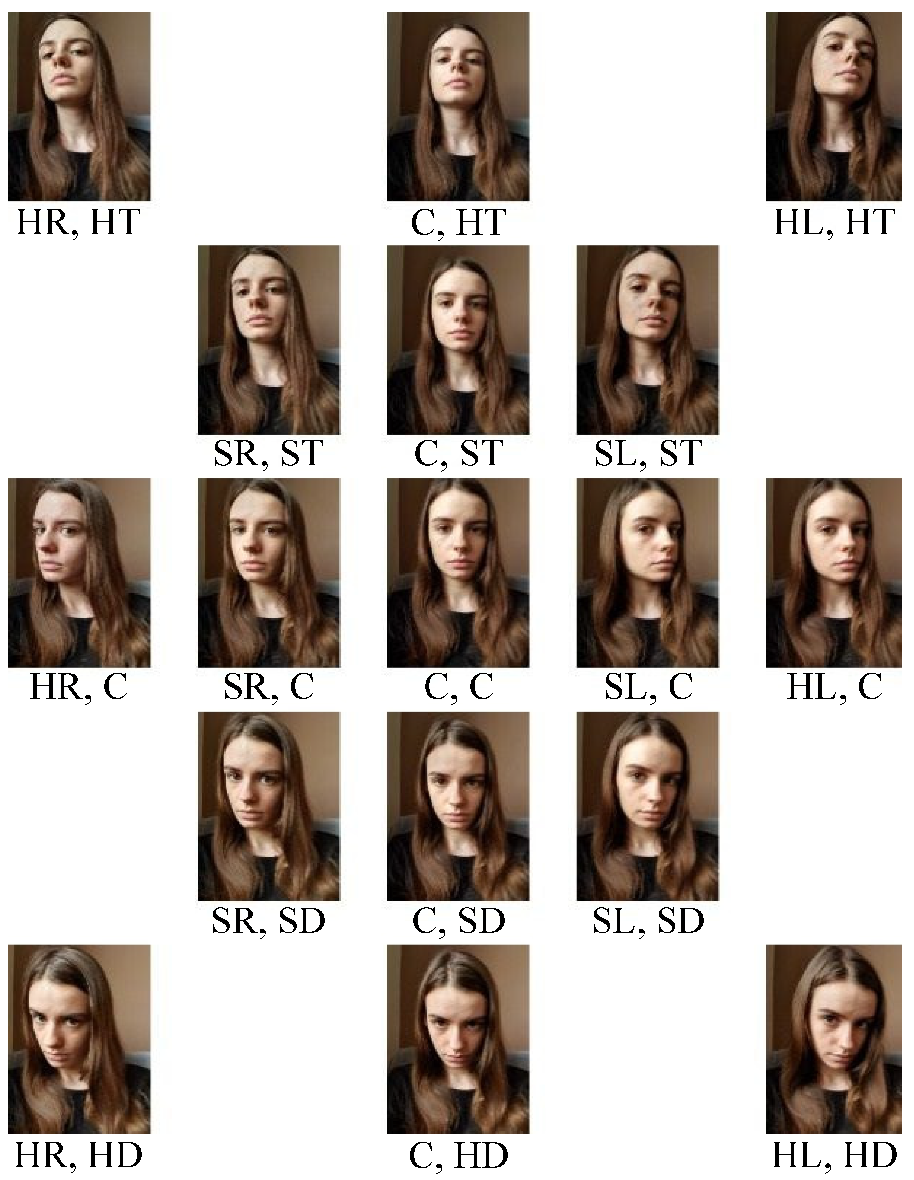
First, a set of 17 classes directly connected with different head orientations was proposed. At first, the whole grid of 25 possible orientations was considered. However, the membership of certain images in a given class was ambiguous because of similarities between them. Therefore, a few classes that were irrelevant in terms of the control signal (e.g., HR, ST) were omitted. The set of examples of images representing all orientations is presented in
Figure 2, whereas the corresponding output classes are gathered in
Table 1. Head orientation is described as a pair of output numbers: (Horizontal orientation, Vertical orientation). For example, the head orientation depicted in the lower-left image in
Figure 2 is denoted as (HR, HD), which represents the horizontal hard right orientation and the vertical hard left orientation. For each direction, five different orientations were distinguished.
A total of 71 volunteers were asked to collect a set of 17 pictures, each similar to the example set. The volunteers had been instructed to keep the orientation of the head comfortable. They were asked to collect images at the center orientation, hard directional orientations, and slightly directional orientations in between the two previous ones. In each image, both eyes had to be visible, and the person should look in the direction of the screen.
In particular, each image collection was acquired by a different non-professional camera with different final resolution and aspect ratio of the image. This was intentional, as the final application should estimate the head orientation on image frames from different amateur sources, e.g., web cameras. The resolution varied from 352 px to 4032 px.
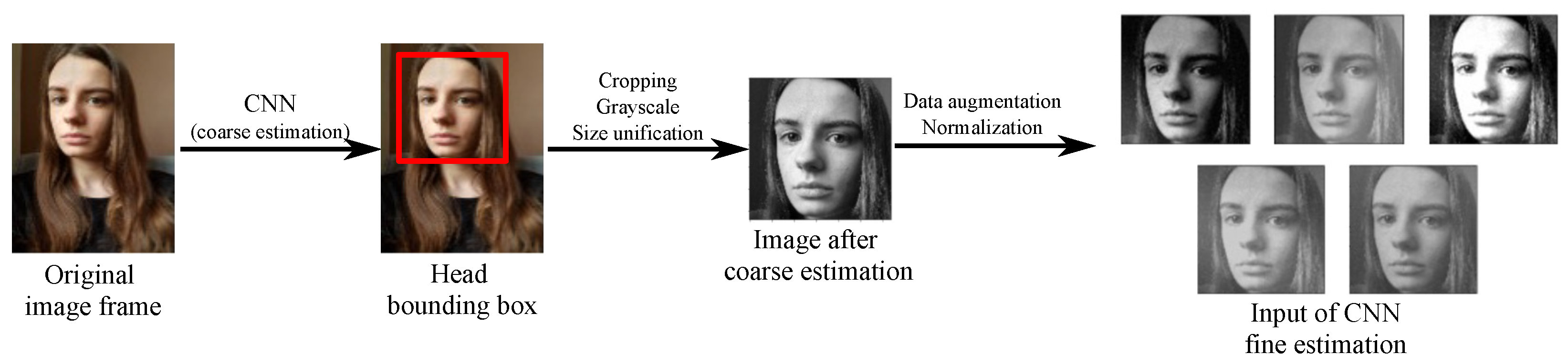
Due to the wide variety of characteristics of the image data, a prior unification of the size was required. The coarse CNN (denoted in
Figure 1) was used to this end. The main goal of coarse estimation was to detect the head bounding box. The coarse estimation output data consisted of four corners of the bounding box. The corners of the bounding box were subsequently used to crop the images. The example result of this part of the algorithm is presented as the first step in
Figure 3.
The cropped images were preprocessed to constitute a valid training set of fine CNN estimation, as presented in
Figure 3. First, the unified size was experimentally chosen to be 128
px, and the color information was discharged. Second, the image dataset was augmented by transforming the original image frames with typical operations (contrast change, noise addition, lightning change, and mirror reflection). Third, the features of the image were scaled to the range
, to ensure proper training.
The entire image dataset was divided into training, development, and test sets, as described in
Table 2. The data augmentation process enlarged the learning set sizes ten times. In particular, the images representing an individual were never scattered through different learning sets. Additionally, the test set consisted of original images without augmentation. Each of the three volunteers in the test set collected head images with different orientations, similar to the example in
Figure 2. The images were collected with the webcam that was used in the final application. Each person in the test set was asked to collect three sets of images with different lighting conditions to verify performance in a data distribution similar to the final application.
2.2. CNN Estimator
2.2.1. Coarse Estimation
The main goal of coarse head estimation is to detect the position of the head in the image and estimate its bounding box. In this project, four different solutions of head detection were evaluated, namely, the Haar cascade face detector [
22], multitask cascaded convolutional networks (MTCNN) [
23], histogram of oriented gradients (HOG) face detector with the support-vector machine (SVM) [
24], and the DNN module in OpenCV [
25]. Each detector was evaluated in terms of the processing time of a single image frame and accuracy. The results are collected in
Table 3.
The tests have shown that an OpenCV DNN module acts superior in terms of processing time. There were additional problems with alternative solutions. The Haar-based detector resulted in many false predictions, whereas the HOG-based detector did not detect faces that covered a small region of an image. Both acted poorly in non-frontal images.
For further work, the detector that gave the shortest processing time was chosen, resulting in an operation close to online. The estimation of the head bounding box was carried out with an OpenCV DNN module with a pre-trained CNN model [
26]. Since no prior modifications were made to the proposed CNN architecture, a detailed review will be omitted in this work.
In particular, the neural network selected for the coarse estimation resulted in regression of the bounding box; that is, the coordinates of the left top corner of the bounding boxes and its height. Different bounding boxes’ sizes could be estimated depending on the dimensions of the head present on a particular image frame. Subsequently, the square image given by the bounding box was cropped from the original image data, as presented in
Figure 3. The size was then unified as
px to constitute a valid fine estimation input, as described in the previous section.
2.2.2. Fine Estimation
The fine estimation classification algorithm proposed in this work assumes the separation of vertical and horizontal orientations. There are several reasons for this. First, it is crucial to enable the online operation of the overall system, and the decomposition of the solution decreases the computational time. Second, the camera mounting used in the considered study has 2DOF; therefore, the decomposition is unavoidable.
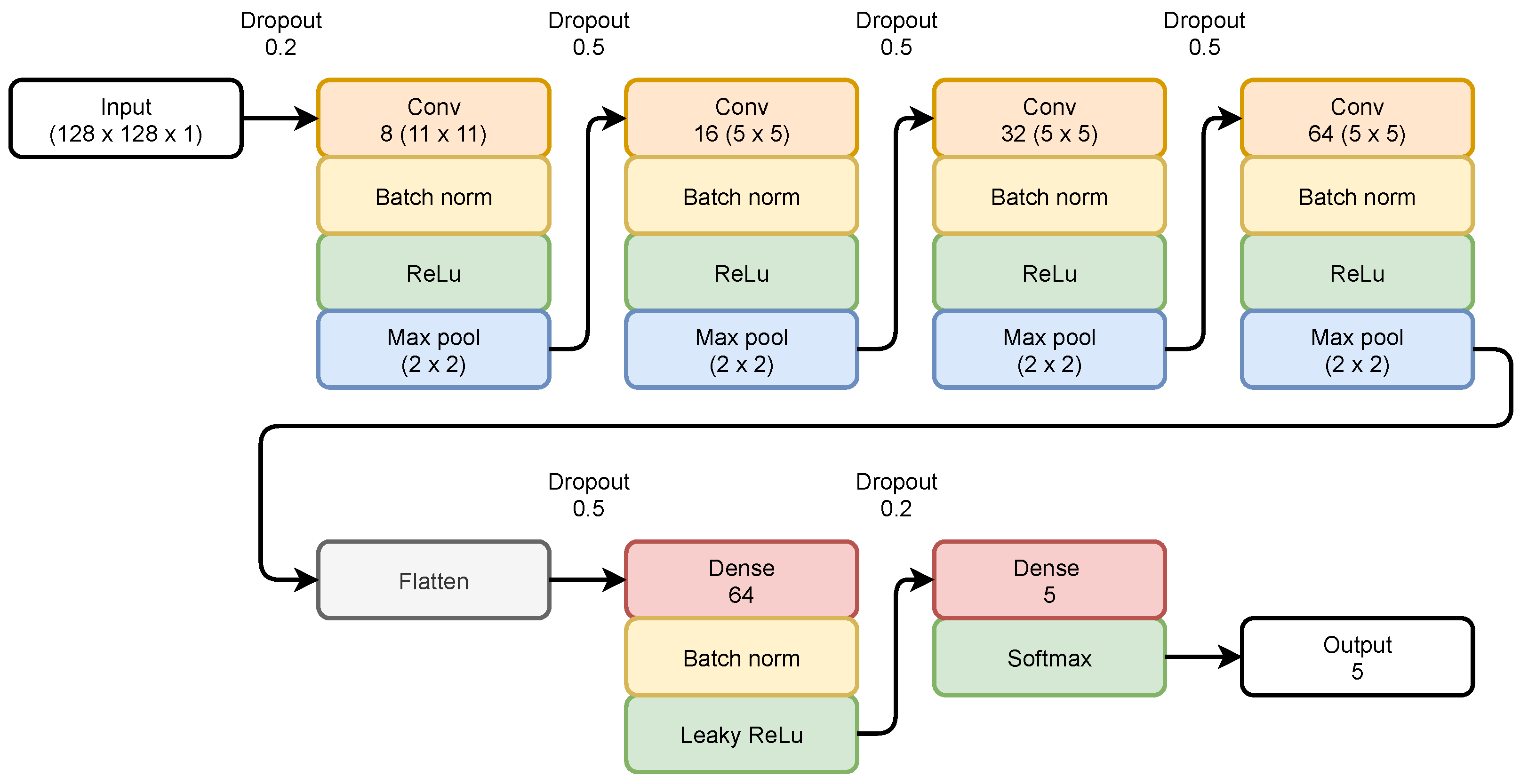
The assumption was made that both CNN estimators (for vertical and horizontal orientations) will have identical architectures. Due to differences between the output data, the hyperparameters will differ. The proposed architecture is presented in
Figure 4. The architecture was inspired by the popular LeNet-5 [
27]. However, complex and customized modifications were needed.
The proposed CNN contains seven layers: four convolutional layers, a flatten layer, and two dense layers. In general, there are 216,501 hyperparameters to train in CNN. Each convolutional layer is followed by Batch Normalization [
28] and a ReLU activation function.
The deeper the layer, the more convolutional filters used and the smaller the image matrix size (due to pooling layers). The last pooling layer outputs the matrix of size . Decreasing the size of the input image throughout the network enables deeper layers of the network to have a larger receptive field and limits the number of hyperparameters of dense layers. The limitation of the hyperparameter number is important in this scenario to not increase the processing time.
The convolutional layers are followed by a flattening layer, resulting in an output vector of size 4096. A one-dimensional vector is passed to a dense layer with a leaky ReLU [
29] activation function. The choice of this activation function limits the probability that dead neurons occur in the deep layers.
The last dense layer is followed by a softmax activation function, and the size of the output vector is equal to the number of classes considered, as described in
Table 1. The output vector contains the probability that the actual image belongs to one of the classes. It should be noted that no negative samples were used for training. Here, two main factors were considered. First, the coarse estimation algorithm [
25] resulted in an empty output if no head was detected in the image; therefore, the fine estimation was fed with meaningful data. Second, it was intentional to always assign one of the output classes, even if a real orientation of the head was slightly out of the classes.
2.3. Hardware
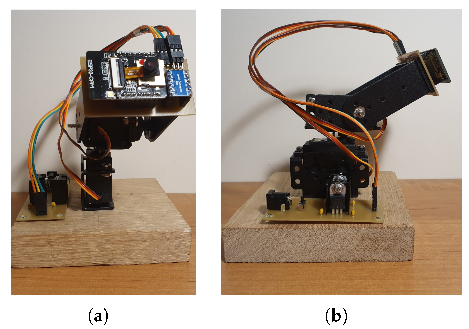
The 2DOF movable camera mounting was built from two separate servomechanisms and an ESP32-CAM board, which has an embedded processing unit, WiFi module, and micro camera that work as a surveillance camera in this project. The overall view of the system is depicted in
Figure 5.
In this study, TowerPro MG995 servomechanisms [
30] were used for both degrees of freedom. Their operating speed is equal to
s for
of position displacement. The velocity was saturated in the software architecture; that is, if a control action was required, every 1 ms, a command was sent to alter the angular position of the servomechanism by
.
Both servomechanisms considered in this study have a controlled movement range of 180. The first drive, which was attached to the base, does not have an extra limit in the moving range. Therefore, movement is limited to 90 in the left direction and 90 in the right direction. The second servomechanism is attached to the output of the first servomechanism. The movement of the second servomechanism was restricted to 30 sagittal flexion down and 60 sagittal flexion up. The limits are directly connected with the CCTV camera image. This solution avoids pointing the camera at unimportant areas of the building (e.g., ceiling, floor). The ESP32-CAM was connected to the second servo rotor to ensure two degrees of freedom of moving mount.
Both sides of the system are energy independent; therefore, the operator can be separated from the CCTV camera as long as they are within range of the same network.
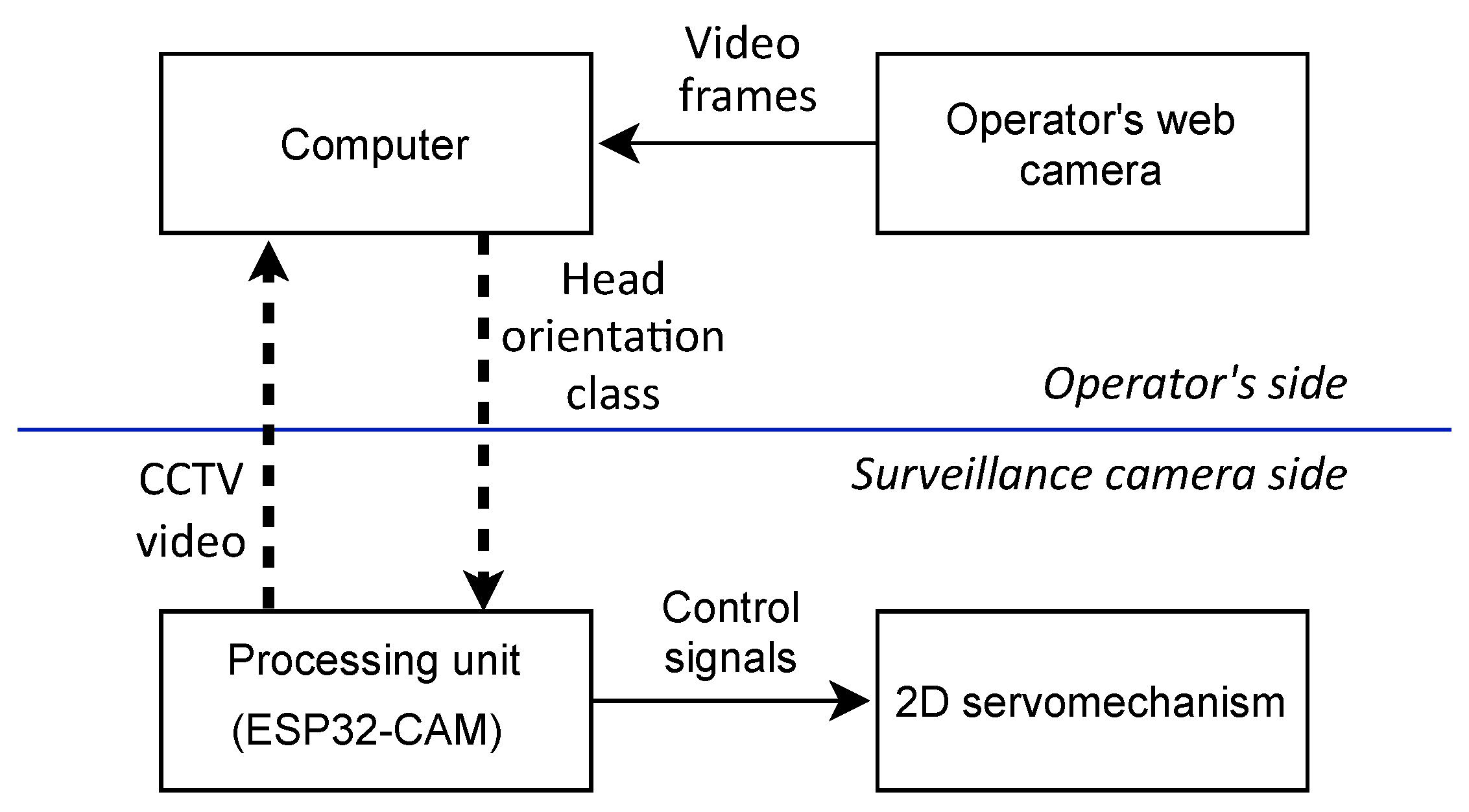
2.4. Data Flow of the Proposed System
The overall system incorporates all components described in previous subsections. The data flow between the components is presented in
Figure 6.
As stated above, the system is divided into two parts: the operator side and the surveillance camera side. On the operator’s side, the head orientation on video frames is estimated. Rare video frames from the operator’s web camera are preprocessed and passed on to a series of CNN estimators. Both preprocessing and estimation are held on the operator’s computer (no need to use GPU computers). The head orientation class, from
Table 1, is wirelessly transmitted to the side of the system’s CCTV camera. In particular, to maintain fast system performance, the information is sent only if a change is detected in the orientation class, either in the vertical or horizontal direction.
Communication between parts of the system is wireless to maintain the compactness and portability of the solution. Additionally, the system does not involve any external network source, as it is designed to create its own WiFi Access Point and dedicated server.
The processing unit (on the surveillance camera side of the system) is responsible for generating the control signal for the servomechanisms. There are two distinct control signals for vertical and horizontal movements of the camera mounting. Several different control strategies were examined on volunteer operators. The one that was the most intuitive and comfortable for the users was chosen.
Moving the operator’s head in each direction generates control signals for vertical and horizontal movement corresponding to that direction. For the users’ convenience, it has been proposed to incorporate the head orientation classes in hysteresis to generate control signals. The most distant head orientations (HT, HD, HL, HR) generate control signals of camera mounting. Slight head orientations (ST, SD, SL, SR) are used as hysteresis of the control signal, causing the previous control action to be maintained. Example control signals for a pair, current and previous head orientation class, are gathered in
Table 4.
The operator can view the video from both cameras; that is, the webcam (with a bounding box) and the CCTV camera. Hysteresis applied to the control action ensured a decrease in operator fatigue. If an operator’s task is to keep the position of the surveillance camera fixed for a given time, slight movements of the head are possible without generating any control action.
3. Results
In this section, the results of the fine estimation of the proposed CNN architecture are presented. Furthermore, the results obtained for the overall system working online are discussed.
3.1. Optimal CNN Estimator
CNN estimators, the architecture of which was described in
Section 2.2, were trained for various learning parameters. The following variables were considered: the learning rate
, the size of the batch
, and different early stopping rules [
31]. The most optimal results, in terms of high accuracy, low loss function value, and proper generalization throughout the learning sets, were obtained for the following set of parameters:
learning rate ,
batch size = 64,
early stopping: learning was terminated when for 20 epochs, the accuracy of the development set did not increase by .
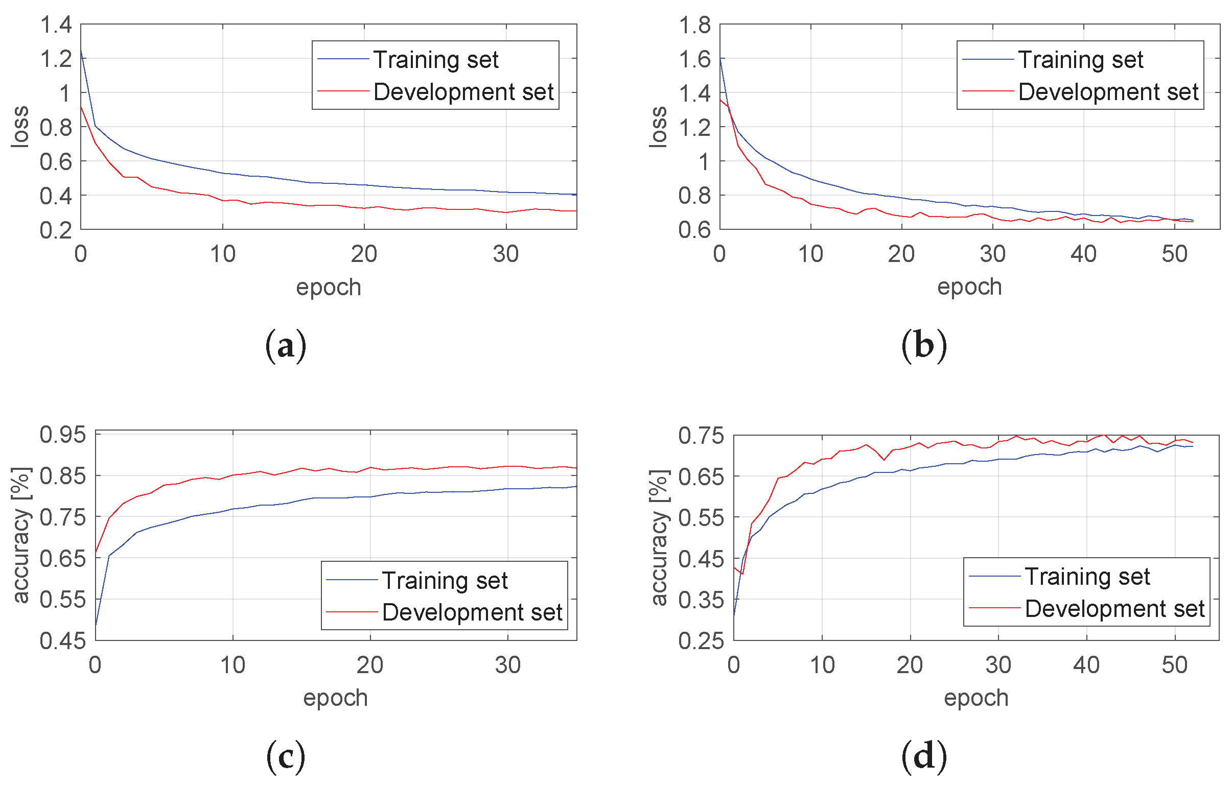
The values of the loss function and the accuracy achieved as a function of the epoch number are presented in
Figure 7. In the case of both estimators, the early stopping rule was met before 60 epochs. No overfitting was observed, as the performance was similar for the training and development sets.
The accuracy achieved from the development and training sets is combined with a test set in
Table 5. Both estimators provided satisfactory results, as they correctly classified head orientation with high accuracy. The horizontal estimator acted better, and the reason is directly related to the range of head movements. Previous studies have shown that the normal functional range of motion of the neck during daily activities is higher in the horizontal than in the vertical direction [
32]. The same conclusion can be drawn from the collected images. The accuracy of vertical CNN was reduced due to insignificant changes between the central and slight orientations in this plane of motion.
It is worth pointing out the accuracy gap between training and test sets. The main reason lies in a slightly different distribution of the data in the sets. The test set comprised web camera images that were of better quality (higher resolution, more information, less blurry) than the images gathered from volunteers. The images that were classified incorrectly in the training set by the estimators were mostly of the lowest resolution, and/or the person collecting the image did not follow the instructions of data acquisition precisely.
3.2. Overall System Results
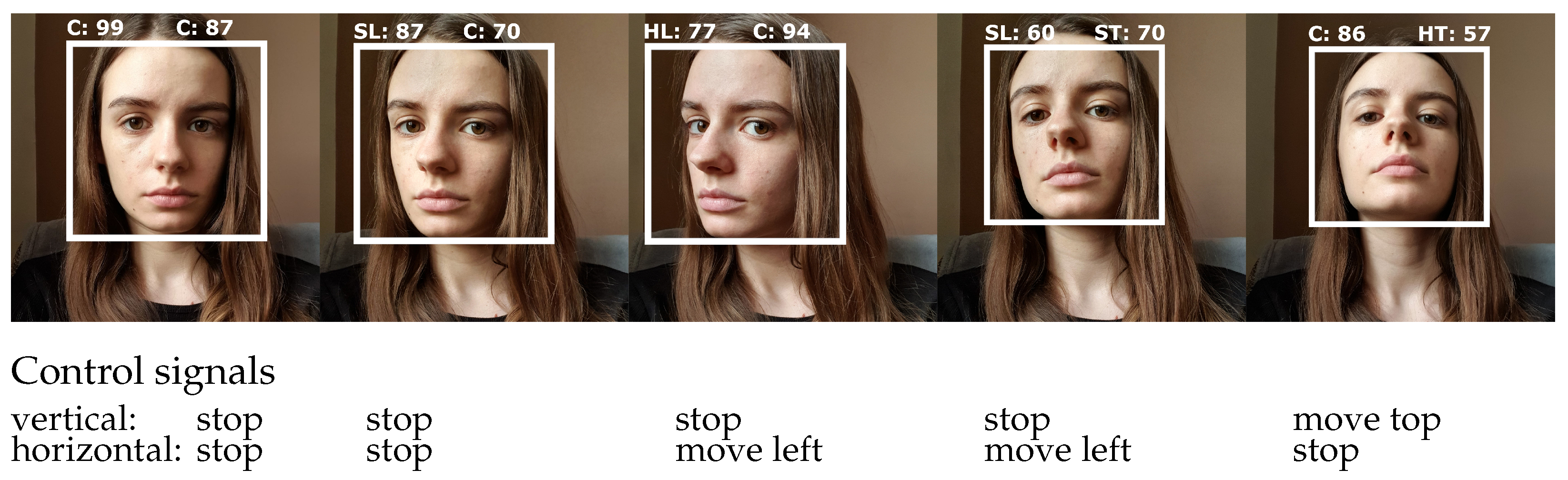
The overall system worked fairly well online. Example image frames with the corresponding head orientation classes, as well as with the resulting control signals, are presented in
Figure 8. The white rectangle represents the bounding box (a result of coarse estimation), while the above annotation represents the output of fine estimation (with assigned probability). The control signal is generated in a hysteresis manner, as described in
Table 4. To begin to increase the angle of camera mounting, the user needs to achieve the most distant directional orientation for an image frame (approximately 40 ms). Afterward, if the estimated orientation class is not the center, the movement of a mounting is maintained in the previously referenced direction.
During the experiments, no false-positive classes of head orientation were observed. Importantly, if any false-positive would occur among neighbor output classes, hysteresis in the control signal would cause the control system to omit these data.
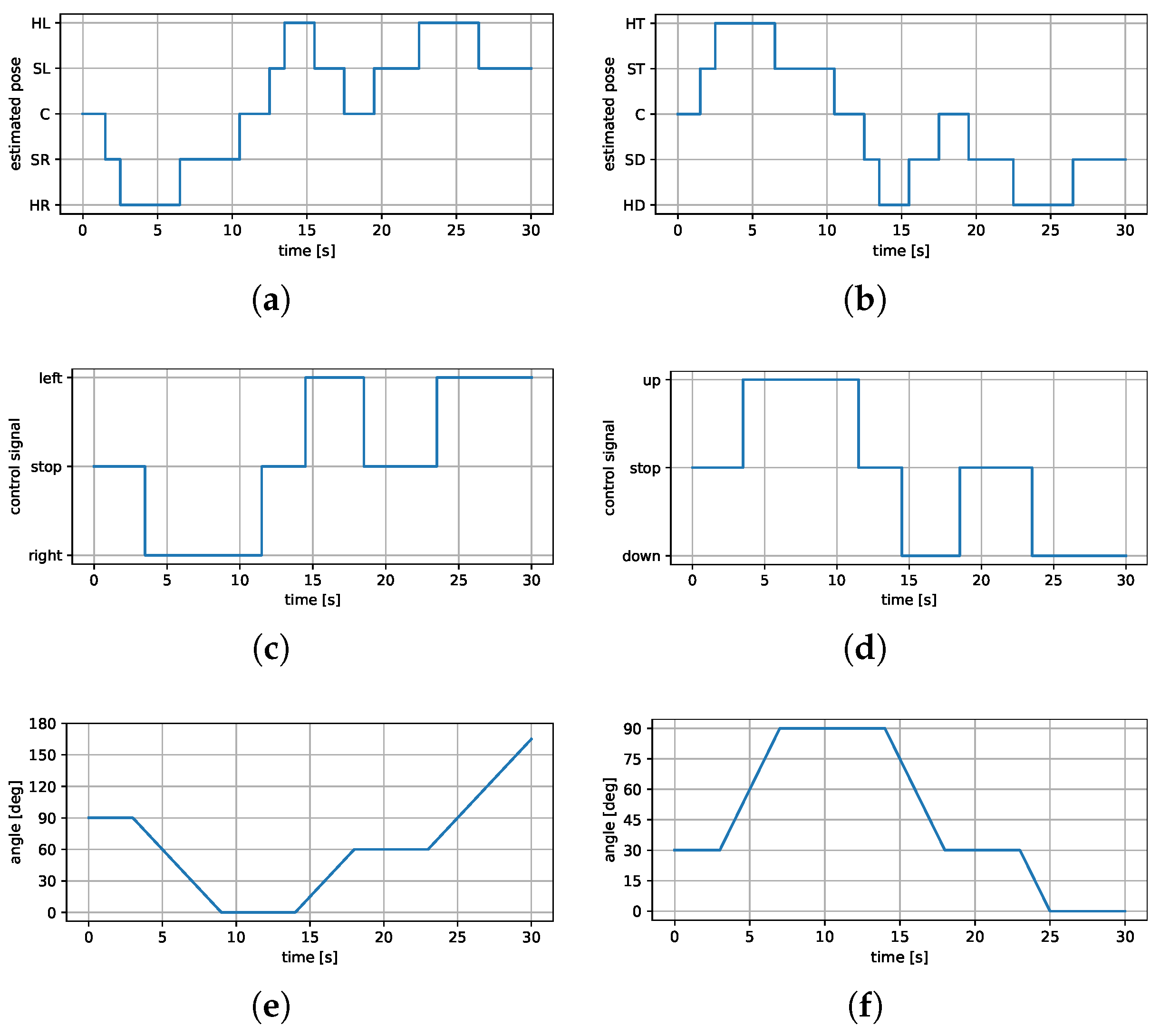
Figure 9 presents time-series plots of one of the movement sequences.
The operator was asked to move their head in the direction of the point of interest of the surveillance camera. Both orientations, horizontal and vertical, were estimated simultaneously, and the corresponding graphs are gathered in
Figure 9.
Figure 9a,b show the estimated orientation of each fine estimator, and
Figure 9c,d show the corresponding control signals. A delay of approximately
s was observed, as predicted for wireless communication between the servomechanism and the PC.
Figure 9e,f present the angle changes for both servomotors. No errors in estimation and control signal generation were observed during the tests. Importantly, users described the system as intuitive and comfortable.
Admittedly, the estimation algorithm presented in this study is limited to a finite set of head orientations. Meanwhile, other approaches consider continuous sets. The choice of discrete values of head orientation was intentional. There was a trade-off between the processing speed and applicability to the CCTV system. The choice of 17 output classes was sufficient to generate a control signal and largely decreased the processing time. The processing time of the whole estimation algorithm (between the acquisition of the input image frame to the final estimation of the head orientation) is gathered in
Table 6. Similar values are presented for alternative solutions discussed previously. Note the difference between
Table 3, which presents results of a part of the algorithm, and
Table 6, which gathers values for the whole estimation. The processing time of the presented solution is approximately seven times shorter compared to the others. The main reason for this is the incorporation of a multiprocessing library, which enables parallel processing. Please note that the proposed solution was partially based on OpenCV’s DNN library, but only for coarse estimation.
4. Discussion
In this work, a complex solution was proposed that allows the control of a CCTV camera for disabled people. The system estimates the user’s head orientation on image frames acquired by the commonly available web camera. Several CNN estimators are used, which work in a coarse-to-fine manner. The first estimates the head position and denotes its bounding box in the image. The second determines the head orientation output class. Separate estimators are used for horizontal and vertical movements, assigning one of the five classes each. The resulting class is used to generate a control signal for the servomechanisms attached to the surveillance camera mount.
To accurately train CNN estimators, the data set reflecting the final application was collected. In each image, a person looked in the direction of the camera, while the orientation of the head differed between the pictures. The range of head tilt and turn was limited by the comfort of each individual. The number of original image frames exceeds 1500, which corresponds to the amount of data in many publicly available and commonly used datasets [
3]. In particular, the collected dataset could be incorporated into other head configuration estimation algorithms.
The experiments carried out on the overall system gave satisfactory results in terms of processing time, accuracy, and ease of use. Fast operation was achieved by dividing the problem into smaller parts (each solved by a different estimator) and optimal communication between the components.
The time between head movement and the corresponding action of the surveillance camera was, on average, equal to s. This includes head detection, orientation class estimation, sending control signals to CCTV, and actual movement. The processing time is not suitable for security applications, e.g., anomaly recognition systems. For this kind of security system, usually, the camera mounting needs to follow fast-moving objects, contrary to CCTV applications, where the camera is wide-angle and its movements are less dynamic. Therefore, the processing speed is sufficient for the problem considered.
The accuracy of the head orientation estimators lies within the results achieved recently [
3]. However, the accuracy tends to decrease for a larger number of output classes. In this work, the number of possible estimated head orientations is limited to 17, which is far from a continuous estimation. Nevertheless, the proposed discrete set of classes is sufficient for a given problem.
Preliminary research has been done on more densely defined output classes. This solution was abandoned due to user dissatisfaction. Our main goal was to create a comfortable system and limit the fatigue of disabled users. Bear in mind that the system is intended to be used for many hours, and it is obvious that holding the head still could be exhausting for everyone. This was the main reason for choosing the hysteresis-based control action for the servomechanisms. The application of hysteresis ensures that slight movements of the head do not activate the servomechanism.
In particular, the images presented people with unique features (complexion, hair color, hairstyle, glasses, mustache, etc.). The only limitation of the gathered dataset is the lack of images of people with beards. Unfortunately, no experiments were conducted for bearded operators, but it is highly probable that the system may result in an erroneous result in this scenario.
Author Contributions
Conceptualization, R.M.S., M.D., M.P. and A.S.; methodology, R.M.S., M.D., M.P. and A.S.; software, R.M.S., M.P. and A.S.; validation, R.M.S., M.P. and A.S.; formal analysis, R.M.S., M.P. and A.S.; investigation, R.M.S., M.P. and A.S.; resources, R.M.S., M.D., M.P. and A.S.; data creation, R.M.S., M.P. and A.S.; writing, R.M.S. and M.D.; supervision and project administration, M.D. All authors have read and agreed to the published version of the manuscript.
Funding
This research was supported by the Poznań University of Technology, statutory grant no. 0211/SBAD/0122 and 5300101;0211; 0010;ND.
Institutional Review Board Statement
Not applicable.
Informed Consent Statement
Written informed consent has been obtained from the participants to publish this paper.
Data Availability Statement
Not applicable.
Acknowledgments
The authors would like to thank all of the volunteers who agreed to participate in the image dataset creation and signed an informed consent to use the data in the scientific research.
Conflicts of Interest
The authors declare no conflict of interest.
References
- Abiyev, R.H.; Arslan, M. Head mouse control system for people with disabilities. Expert Syst. 2020, 37, e12398. [Google Scholar] [CrossRef]
- Wollaston, W.H., XIII. On the apparent direction of eyes in a portrait. Philos. Trans. R. Soc. Lond. 1824, 114, 247–256. [Google Scholar]
- Khan, K.; Khan, R.U.; Leonardi, R.; Migliorati, P.; Benini, S. Head pose estimation: A survey of the last ten years. Signal Process. Image Commun. 2021, 99, 116479. [Google Scholar] [CrossRef]
- Zhang, Z.; Hu, Y.; Liu, M.; Huang, T. Head pose estimation in seminar room using multi view face detectors. In Lecture Notes in Computer Science; Stiefelhagen, R., Garofolo, J., Eds.; Springer: Heidelberg/Berlin, Germnay, 2007; pp. 299–304. [Google Scholar]
- Li, J.; Wang, J.; Ullah, F. An end-to-end task-simplified and anchor-guided deep learning framework for image-based head pose estimation. IEEE Access 2020, 8, 42458–42468. [Google Scholar] [CrossRef]
- Hsu, H.W.; Wu, T.Y.; Wan, S.; Wong, W.H.; Lee, C.Y. Quatnet: Quaternion-based head pose estimation with multiregression loss. IEEE Trans. Multimed. 2018, 21, 1035–1046. [Google Scholar] [CrossRef]
- Jain, V.; Crowley, J.L. Head pose estimation using multi-scale Gaussian derivatives. In Proceedings of the 18th Scandinavian Conference on Image Analysis, Espoo, Finland, 28 June 2013. [Google Scholar]
- Barra, P.; Barra, S.; Bisogni, C.; De Marsico, M.; Nappi, M. Web-shaped model for head pose estimation: An approach for best exemplar selection. IEEE Trans. Image Process. 2020, 29, 5457–5468. [Google Scholar] [CrossRef]
- Nabati, M.; Behrad, A. 3D head pose estimation and camera mouse implementation using a monocular video camera. Signal Image Video Process. 2015, 9, 39–44. [Google Scholar] [CrossRef]
- Ranjan, R.; Patel, V.M.; Chellappa, R. Hyperface: A deep multi-task learning framework for face detection, landmark localization, pose estimation, and gender recognition. IEEE Trans. Pattern Anal. Mach. Intell. 2017, 41, 121–135. [Google Scholar] [CrossRef] [PubMed] [Green Version]
- Li, Z.; Fu, Y.; Yuan, J.; Huang, T.S.; Wu, Y. Query driven localized linear discriminant models for head pose estimation. In Proceedings of the 2007 IEEE International Conference on Multimedia and Expo, Beijing, China, 8 August 2007; pp. 1810–1813. [Google Scholar]
- Yu, Y.; Mora, K.A.F.; Odobez, J.-M. Robust and accurate 3d head pose estimation through 3dmm and online head model reconstruction. In Proceedings of the 2017 12th IEEE International Conference on Automatic Face & Gesture Recognition (FG 2017), Washington, DC, USA, 30 May–3 June 2017. [Google Scholar]
- Ruiz, N.; Chong, E.; Rehg, J.M. Fine-grained head pose estimation without keypoints. In Proceedings of the 2018 IEEE Conference on Computer Vision and Pattern Recognition Workshops, Salt Lake City, UT, USA, 18–22 June 2018; pp. 2074–2083. [Google Scholar]
- Cao, Q.; Shen, L.; Xie, W.; Parkhi, O.M.; Zisserman, A. Vggface2: A dataset for recognising faces across pose and age. In Proceedings of the 2018 IEEE International Conference on Automatic Face and Gesture Recognition, Xi’an, China, 15–19 May 2018; pp. 67–74. [Google Scholar]
- Köestinger, M.; Wohlhart, P.; Roth, P.M.; Bischof, H. Annotated facial landmarks in the wild: A large-scale, real-world database for facial landmark localization. In Proceedings of the 2011 IEEE International Conference on Computer Vision Workshops, Barcelona, Spain, 6 November 2011; pp. 2144–2151. [Google Scholar]
- Lüsi, I.; Junior, J.C.J.; Gorbova, J.; Baró, X.; Escalera, S.; Demirel, H.; Allik, J.; Ozcinar, C.; Anbarjafari, G. Joint challenge on dominant and complementary emotion recognition using micro emotion features and head-pose estimation: Databases. In Proceedings of the 12th IEEE International Conference on Automatic Face and Gesture Recognition, Washington, DC, USA, 3 May 2017; pp. 809–813. [Google Scholar]
- Black, J., Jr.; Gargesha, M.; Kahol, K.; Kuchi, P.; Panchanathan, S. A framework for performance evaluation of face recognition algorithms. In Proceedings of the SPIE—The International Society for Optical Engineering, Boston, MA, USA, 31 July 2002. [Google Scholar]
- Gu, J.; Yang, X.; De Mello, S.; Kautz, J. Dynamic facial analysis: From Bayesian filtering to recurrent neural network. In Proceedings of the 2017 IEEE Conference on Computer Vision and Pattern Recognition, Honolulu, HI, USA, 21–26 July 2017; pp. 1548–1557. [Google Scholar]
- Kuhnke, F.; Ostermann, J. Deep head pose estimation using synthetic images and partial adversarial domain adaption for continuous label spaces. In Proceedings of the 2019 IEEE International Conference on Computer Vision, Seoul, Korea, 27 Octorber–2 November 2019; pp. 10164–10173. [Google Scholar]
- Singh, V.; Singh, S.; Gupta, P. Real-Time Anomaly Recognition Through CCTV Using Neural Networks. Procedia Comput. Sci. 2020, 173, 254–263. [Google Scholar] [CrossRef]
- Rezaei, Y.A.; Heisenberg, G.; Heiden, W. User Interface Design for Disabled People Under the Influence of Time, Efficiency, and Costs. In Proceedings of the 2014 HCI International, Crete, Greece, 22–27 June 2014; pp. 197–202. [Google Scholar]
- Chandrappa, D.N.; Akshay, G.; Ravishankar, M. Face Detection Using a Boosted Cascade of Features Using OpenCV. In Wireless Networks and Computational Intelligence, ICIP 2012, Communications in Computer and Information Science; Venugopal, K.R., Patnaik, L.M., Eds.; Springer: Berlin/Heidelberg, Germnay, 2012; pp. 399–404. [Google Scholar]
- Zhang, K.; Zhang, Z.; Li, Z.; Qiao, Y. Joint Face Detection and Alignment using Multi-task Cascaded Convolutional Networks. IEEE Signal Process. Lett. 2016, 23, 1499–1503. [Google Scholar] [CrossRef] [Green Version]
- Dalal, N.; Triggs, B. Histograms of oriented gradients for human detection. In Proceedings of the IEEE Computer Society Conference on Computer Vision and Pattern Recognition, San Diego, CA, USA, 20–25 June 2005. [Google Scholar]
- OpenCV’s DNN Module Code. Available online: https://github.com/opencv/opencv/tree/master/modules/dnn (accessed on 24 November 2021).
- Head Pose Estimation. Available online: https://github.com/yinguobing/head-pose-estimation (accessed on 21 November 2021).
- Lecun, Y.; Bottou, L.; Bengio, Y.; Haffner, P. Gradient-based learning applied to document recognition. Proc. IEEE 1998, 86, 2278–2324. [Google Scholar] [CrossRef] [Green Version]
- Ioffe, S.; Szegedy, C. Batch Normalization: Accelerating Deep Network Training by Reducing Internal Covariate Shift. In Proceedings of the 32nd International Conference on Machine Learning, Lille, France, 7–9 July 2015; pp. 448–456. [Google Scholar]
- Maas, A.L.; Hannun, A.Y.; Ng, A.Y. Rectifier nonlinearities improve neural network acoustic models. In Proceedings of the International Conference on Machine Learning, Atlanta, GA, USA, 16–21 June 2013. [Google Scholar]
- TowerPro MG995 Manual. Available online: https://www.towerpro.com.tw/product/mg995/ (accessed on 21 April 2022).
- Yao, Y.; Rosasco, L.; Caponnetto, A. On Early Stopping in Gradient Descent Learning. Constr. Approx. 2007, 26, 289–315. [Google Scholar] [CrossRef]
- Bible, J.E.; Biswas, D.; Miller, C.P.; Whang, P.G.; Grauer, J.N. Normal Functional Range of Motion of the Cervical Spine During 15 Activities of Daily Living. J. Spinal Disord. Tech. 2010, 23, 15–21. [Google Scholar] [CrossRef] [PubMed]
Figure 1.
Simplified schematic of the proposed system. Image data captured by a webcam on the operator’s side of the system is evaluated in a coarse-to-fine manner via two independent neural network architectures. The head orientation in vertical and horizontal planes is used to calculate the corresponding control action fed to the CCTV camera mounting.
Figure 2.
Example image set with the 17 assigned output classes.
Figure 2.
Example image set with the 17 assigned output classes.
Figure 3.
Data flow of CNN valid image dataset preparation. The original image data are fed to a coarse estimation, which results in the square head bounding box. The cropped image is unified in size, normalized, and preprocessed for training purposes.
Figure 3.
Data flow of CNN valid image dataset preparation. The original image data are fed to a coarse estimation, which results in the square head bounding box. The cropped image is unified in size, normalized, and preprocessed for training purposes.
Figure 4.
Fine estimation CNN architecture. Each block represents a different part of the CNN: red—convolution layer, orange—batch normalization, green—activation function, blue—pooling layer, magenta—dense layer, white—input and output layer.
Figure 4.
Fine estimation CNN architecture. Each block represents a different part of the CNN: red—convolution layer, orange—batch normalization, green—activation function, blue—pooling layer, magenta—dense layer, white—input and output layer.
Figure 5.
The 2DOF mounting system of CCTV with ESP32-CAM board. (a) Front view. (b) Side view.
Figure 5.
The 2DOF mounting system of CCTV with ESP32-CAM board. (a) Front view. (b) Side view.
Figure 6.
Data flow between the basic components of the proposed system; solid lines represent wire connections, whereas dashed lines denote wireless connections.
Figure 6.
Data flow between the basic components of the proposed system; solid lines represent wire connections, whereas dashed lines denote wireless connections.
Figure 7.
The results for all learning sets for both estimators: horizontal and vertical. (a) Loss function (horizontal). (b) Loss function (vertical). (c) Accuracy (horizontal). (d) Accuracy (vertical).
Figure 7.
The results for all learning sets for both estimators: horizontal and vertical. (a) Loss function (horizontal). (b) Loss function (vertical). (c) Accuracy (horizontal). (d) Accuracy (vertical).
Figure 8.
Video frames from the camera pointed at the operator’s face. The white rectangle represents the head bounding box, whereas the values above describe the head estimation output class, together with probabilities.
Figure 8.
Video frames from the camera pointed at the operator’s face. The white rectangle represents the head bounding box, whereas the values above describe the head estimation output class, together with probabilities.
Figure 9.
Estimated head orientation, corresponding control signals, and the resulting angle change of the CCTV camera. The left column represents the movement in the horizontal direction, whereas the second—vertical. (a) Estimated orientation (horizontal). (b) Estimated orientation (vertical). (c) Control signals (horizontal). (d) Control signals (vertical). (e) Servomechanism angle (horizontal). (f) Servomechanism angle (vertical).
Table 1.
Summary of the proposed output data classes.
Table 1.
Summary of the proposed output data classes.
| Horizontal | Vertical |
|---|
| Head Orient. | Output Class | Head Orient. | Output Class |
|---|
| Hard Left (HL) | 0 | Hard Top (HT) | 0 |
| Slightly Left (SL) | 1 | Slightly Top (ST) | 1 |
| Center (C) | 2 | Center (C) | 2 |
| Slightly Right (SR) | 3 | Slightly Down (SD) | 3 |
| Hard Right (HR) | 4 | Hard Down (HD) | 4 |
Table 2.
Number of image frames in each learning set.
Table 2.
Number of image frames in each learning set.
| | Training Set | Development Set | Test Set |
|---|
| Original sets | 1586 | 283 | 153 |
| Augmented sets | 15,860 | 2830 | 153 |
| Number of people | 51 | 15 | 3 |
Table 3.
Comparison of the time needed to process a single image frame.
Table 3.
Comparison of the time needed to process a single image frame.
| Head detector | Haar | HOG + SVM | MTCNN | OpenCV’s DNN |
| Processing time | ms | ms | ms | ms |
| Accuracy | | | | |
Table 4.
Control signals for example pairs of current and previous head orientation classes.
Table 4.
Control signals for example pairs of current and previous head orientation classes.
| Vertical Movement | Horizontal Movement |
|---|
Current
Orient. | Previous
Orient. | Control
Signal | Current
Orient. | Previous
Orient. | Control
Signal |
|---|
| SL | C | stop | ST | C | stop |
| SL | HL | move left | ST | HT | move top |
| SR | C | stop | SD | C | stop |
| SR | HR | move right | SD | HD | move bottom |
Table 5.
The accuracy of both optimal orientation estimators.
Table 5.
The accuracy of both optimal orientation estimators.
| | Horizontal | Vertical |
|---|
| Training set | 84.72% | 79.50% |
| Validation set | 86.71% | 74.73% |
| Test set | 91.89% | 81.76% |
Table 6.
The results of an experimental comparison of accuracy and time needed to process a single image frame for several different algorithms.
Table 6.
The results of an experimental comparison of accuracy and time needed to process a single image frame for several different algorithms.
| Neural network | Our proposition | MTCNN [23] | OpenCV’s DNN [25] |
| Average processing time | ms | ms | ms |
| Accuracy | | | |
| Publisher’s Note: MDPI stays neutral with regard to jurisdictional claims in published maps and institutional affiliations. |
© 2022 by the authors. Licensee MDPI, Basel, Switzerland. This article is an open access article distributed under the terms and conditions of the Creative Commons Attribution (CC BY) license (https://creativecommons.org/licenses/by/4.0/).


