Article

Structural Design and Dynamic Simulation Optimization of the Triggering Device in a Pressure-Holding Controller for Deep in Situ Coring

1
School of Mechanical Engineering, Sichuan University, Chengdu 610065, China
2
Key Laboratory of Deep Earth Science and Engineering, Sichuan University, Chengdu 610065, China
*
Author to whom correspondence should be addressed.
Appl. Sci. 2022, 12(10), 4961; https://doi.org/10.3390/app12104961
Submission received: 31 March 2022 / Revised: 28 April 2022 / Accepted: 3 May 2022 / Published: 13 May 2022

Abstract

:
As Earth’s shallow coal resources are gradually depleted, humans turn their mining operations to deeper regions. However, because the mechanics of deep-rock masses have not been fully established, the development of deep resources lacks theoretical guidance, and the continuity of such engineering activities is poor. The basis of deep-rock mechanics theory is to achieve deep in situ rock fidelity coring (including the maintenance of pore pressure and temperature). To achieve this goal, deep in situ pressure-holding coring technology is needed. The pressure-holding controller is the key corer component for realizing deep in situ pressure-holding and coring technology. The flap-valve-type pressure-holding controller driven by an elastic force or gravity alone is not enough to provide the initial sealing pressure for the sealing surface. Therefore, a trigger mechanism that assists the pressure-holding controller in achieving closing and initial sealing was designed. Then, the action and friction characteristics of the triggering mechanism were calculated according to the experimental dynamics simulation calculations of different closing characteristics that are affected by gravity in pressure-holding controller space. Optimization was conducted to determine the optimal values of the trigger mechanism spring stiffness, wedge angle, and other parameters. The mechanism can provide technical support for deep pressure-holding coring and improve the pressure-holding power of deep in situ rock coring.

1. Introduction

Coal resources have been mined for hundreds of years. The depth of coal mining has reached 1500 m. Coal resources in the shallow part of Earth have gradually been exhausted, and coal mining has gradually shifted to the deep part of Earth [1]. Coal resources buried below 1000 m in China amount to 5.57 trillion tons, accounting for 53% of known coal resources. Therefore, mining coal resources needs to be implemented in the deep part of Earth. Due to the gradual deepening of mining depth, traditional mining technology faces problems of a low mining rate, ecological environment degradation, and frequent disasters. Xie et al. [2] proposed a fluidized mining system that converts minerals in deep formations into gas, liquid, electricity, heat, or mixed gas–liquid–solid substances, and transports them to the surface to realize clean, efficient, and environmentally friendly deep resource mining. This mining method is a large change from traditional mining, which uses an unmanned shield boring machine to cut coal ore, and mechanical crushing or chemical methods to further process mineral rocks. The disturbance generated by this process inevitably damages, deforms, and destroys local rocks. Exploring rock mechanics theory regarding the disturbance of in situ mechanical fluidized mining of deep-rock mass is one of the key theories for the fluidized mining of deep resources [3,4,5]. However, current deep-rock mass engineering operations are far ahead of deep-rock mass mechanics theory.
A deep in situ pressure-holding coring tool can be used to obtain the in situ pressure-holding core of deep-rock mass, which is necessary to explore the nonlinear mechanical behavior of deep-rock mass in a mining stress state [6,7,8,9,10]. Pressure-holding coring is mostly used in the exploration and evaluation of resources such as oil, natural gas, and natural gas hydrate. A representative pressure core barrel (PCB) was developed by the Deep Sea Drilling Program (DSDP) [11], advanced piston corer and pressure core samplers were developed by the Ocean Drilling Program (ODP) [12,13], hydrate autoclave coring equipment (HYACE) and hydrate rotary corer (HRC) were developed for research sponsored by the European Union’s Marine Science and Technology Program [14,15], and multiple autoclave corer (MAC) and dynamic autoclave piston corer (DAPC) were developed by the University of Bremen, Germany [16]. There is also a gravity piston-type gas hydrate high-fidelity coring device that was developed by Zhejiang University in China [17], a pressure and temperature preservation system (PTPS) that was developed by Zhu et al. [18], and an ice-valve-based pressure-coring system that was developed at Jilin University to replace traditional mechanical valves for gas hydrate coring experiments [19,20].
In recent years, the application of pressure-preserving and gas-preserving coring in deep coal seams has gradually increased for the prevention and control of coal mine gas disasters, and for the exploration and evaluation of coalbed methane resources [21,22]. The State Key Laboratory of Coal Mine Disaster Dynamics and Control, Chongqing University, China uses a freezing sampler for methane-bearing coal sampling [23]. Gao et al. [3,7,24], and others developed a pressure-maintaining gas-retaining coring tool to achieve low-disturbance coring in deep coal.
Xie et al. [25], and others proposed a pressure-holding controller for a deep in situ pressure-holding corer, as shown in Figure 1, which uses a geometrical die intersecting a hollow cylinder and a cone to design and complete the sealing of a large-flow fluid at the bottom of the hole. The controller consists of three parts: a valve cover, valve seat, and hinge; the valve cover is turned 90 degrees along the hinge to complete the closing. Maximal bearing pressure of more than 100 MPa can be achieved [26,27,28,29], so the application of this controller is relatively extensive. However, when the pressure-holding controller enters the soft sealing state or the metal sealing state, since the metal surface has a machining tool path that is not completely flat, a specific liquid flow channel is formed along the middle of the contact surface [30]. This renders the face leak rate of the packing controller exponentially dependent on the initial pressure. To allow for the pressure-holding controller to enter the initial sealing stage, the O-ring seal must obtain sufficient initial compression to form a dense main contact surface [31,32]. In this paper, a mechanical trigger mechanism for applying a pressure-holding controller was designed to improve the reliability of flap-valve sealing, and the mechanism dynamics was optimized to improve the performance of a deep in situ pressure-holding corer controller in terms of holding success rate.

2. Trigger Mechanism Structural Design

Due to the need to reserve space for the extraction channel of the core, the available design space in the coring chamber is very limited. Therefore, a mechanical trigger mechanism using a combination of spring force and a contact pin was designed to assist the pressure-holding controller in completing the initial sealing. The structure can conserve the internal space of the pressure-maintaining core-removing device. As shown in Figure 2a, in the initial state of the core remover, the trigger mechanism was installed at the bottom of the core pressure-holding tank, and it sits on the valve seat of the pressure-holding controller to fix the valve cover of the pressure-holding controller at the position where it fits with the inner wall of the outer cylinder of the pressure-holding chamber (initial position). The trigger mechanism consists of the following parts: a pressure spring, a stabilizing sleeve, three contact pins spaced 120 degrees apart, the outer tube of the corer, a core barrel, and its tube shoe. The pressure-holding controller and the trigger mechanism work together to ensure that the deep in situ core corer pressure-holding chamber maintains deep in situ pressure; the valve cover of the pressure-holding controller is installed in the interlayer space between core corer outer tube and core barrel, and valve. A tension spring is arranged between seat and valve cover to provide power to close the valve cover. When the corer completes the drilling action, the core tube is filled with the in situ core obtained from drilling. At that time, the pressure-holding corer starts the pressure-holding operation process, as shown in Figure 2b. This process can be divided into the four following stages: (1) Drilling: the corer follows the outer drill to complete the drilling, the core barrel is filled with the captured in situ core, and the core barrel is pulled upwards. (2) Triggering: when the tube shoe of the core barrel is in contact with the contact pin of the trigger mechanism, it starts to drive the contact pin and the sleeve to lift up and compress the pressure spring. (3) Locking: the contact pin reaches the groove position on the inner wall of the outer cylinder of the pressure-holding chamber, and the contact pin rotates along its axis to insert into the groove and lock the sleeve at that vertical height. Since the pressure-holding controller is not fixed by the sleeve, it is closed by its own weight and spring force. (4) Unlocking: the tube shoe of the core barrel is further raised to the target position, the contact pin self-unlocks, and the sleeve springs back.
The three contact pins were evenly installed on the stable sleeve at a circumferential interval of 120 degrees. During the entire action process of the pressure-maintaining coring operation, the trigger mechanism can easily reach a state of force balance in the horizontal direction, preventing the damage caused by the core tube and the core. The mechanism is stuck due to the eccentric moment of the stabilizer sleeve.

3. Kinetic Model of Trigger Mechanism

3.1. Dynamic Model of Closing and Sealing Mechanism of Pressure-Holding Controller

The spring between the valve cover and valve seat of the pressure-holding controller, and the self-gravity of the valve cover provide the power to close the valve cover. Since the valve cover is affected by the gravitational field, the closing characteristics of the valve cover are different when the core is cored at different azimuth angles. The closing time of the valve cover and the maximal jump height determine the allowable rebound time of the sleeve in the trigger mechanism. It is necessary to explore the closing laws of the pressure-holding controller with different azimuth angles through the closed model that is established under the influence of elastic force and gravity field.
To ensure that there is enough pressure to allow for the closed pressure-holding controller reach the initial sealing state, the pressure spring must have sufficient pretightening elastic force. Moreover, when the pressure-holding controller is closed, the sleeve must rebound at a lower speed to ensure safety. The sequence in which the valve cover of the pressure controller first closes the sleeve and then rebounds is usually contradictory. Therefore, to restrain the growth of the sleeve kinetic energy during the rebound process and increase the closing time of the valve cover, the viscous friction force of the O-ring is used to reduce the rebound speed of the stable sleeve to ensure that the valve cover of the pressure-holding controller is closed first and stably. The action sequence of the rear compression of the sleeve simultaneously ensures a sufficient initial sealing pressure for the pressure-holding controller. To render the trigger mechanism robust, the springback time of the sleeve must be higher than a certain safety threshold of the closing time of the pressure-holding controller when coring is required at all angles.
The nitrile rubber material O-ring is a viscoelastic body that has the characteristics of geometric nonlinearity, material nonlinearity, and contact nonlinearity within a certain range. For surface contact between O-ring and metal parts, the increase in surface roughness and compression rate of the metal parts causes the surface friction force of the two to rapidly increase. When the surface roughness and compression rate of the sleeve tube are the same, friction force increases with relative sliding speed. According to the actual machining roughness level of the sleeve parts, the simulated surface roughness was 0.8 μm, and the interpolation function of the sleeve springback is calculated from 0 to 400 mm/s using an O-ring of nitrile rubber material with a compression rate of 0.1. Experimental data of the friction force of the sliding speed can be fitted with a quadratic parabola within a certain relative sliding speed range [33], and the fitting curve of the friction force with relative sliding speed is shown in Figure 3. The fitting function is:
f = 0.00309 v 2 0.08308 v + 6.6039
The springback law of the sleeve is explored with different inclination angles and spring stiffnesses of the corer under the action of the frictional resistance of the O-ring. The springback model is equivalent to a quadratic parabolic single-degree-of-freedom vibration model with a variable damping coefficient. The sleeve moves under the combined action of its own gravity, the elastic force, and the O-ring frictional resistance. Comparing the spring drive with the general fixed damping ratio, the spring model with a variable damping coefficient of quadratic parabola had a better effect on speed control. Its vibration equation is as follows:
T = T 0 + k ( l x )
m a = T + m g cos θ f
where T is spring force, x is displacement, k is stiffness, l is total stroke length, and θ is the angle between coring device and vertical direction during coring. Elastic force T 0 of the initial seal was set to 100 N. The springback simulation model under different angles could be established by using ADAMS software.

3.2. Contact Mechanics Modelling of Contact Pins

The impact-function and compensation methods were used to calculate contact force. For contact modelling under ADAMS, we adopted the collision-function method. The shock-function method calculates contact force on the basis of Hertzian elastic contact theory, which is essentially modelled as a nonlinear spring damper [34]. Through simulation, ADAMS/Solver can produce a continuous stream of responses, including the acceleration, velocity, position, and force of all elements and points of contact [35]. Contact force is divided into two parts, elastic force and damping force [36]. Taking the collision contact between a small ball and a plane as an example, as shown in Figure 4, the normal force of the contact is given by the following relation:
F N = { k δ e + s t e p ( δ , 0 , 0 , d m a x , c m a x ) δ ˙ ,   δ > 0 0 ,   δ 0
where FN is the normal contact force, and k is the contact stiffness coefficient, which depends on the material and the radius of curvature of the contacting solid surface, and can be expressed by the following formula:
k = 4 3 π ( h i + h j ) R 1 2 ,   R = R i R j R i + R j ,   h k = 1 v k 2 π E k ,   k = i , j
where Ri, vi, and Ei represent the curvature radius, Poisson’s ratio, and the elastic modulus of element i (the 304 stainless steel material designed in this paper had an elastic modulus of 220 GPa), respectively; δ is the penetration depth of the contact point; e is the shape index, which determines the shape of the force-displacement curve. For the material defined in this model, e = 1.5; step is the step function; dmax is the maximal allowable mutual penetration depth; cmax is the maximal value of the damping coefficient; and δ ˙ is the penetration velocity of the contact point. In ADAMS, the instantaneous damping coefficient is a cubic step function of the penetration:
s t e p ( δ , 0 , 0 , d m a x , c m a x ) = { 0 ,   δ 0 c m a x ( δ d m a x ) 2 ( 3 2 δ d m a x ) ,   0 < δ < d m a x   c m a x   δ > d m a x
Friction between contacting surfaces is defined as the Coulomb friction:
f = μ s F N
Figure 5 shows the movement state and force diagram of the contact pin in the trigger mechanism during the whole process from starting to locking and unlocking. The three pictures correspond to the actions in Figure 2b, and describe the force state of the locking and unlocking actions. If the simulation experiment of the mechanism could reach the motion state of the third picture, the design could meet the functional requirements, that is, the sleeve could achieve the rebound giving the initial pressure to the valve cover. Figure 6 is the 3-dimensional design diagram of the trigger mechanism installed in the corer that shows the specific shape of the trigger mechanism. The interaction between contact pin and core tube, tube shoe, and the inner wall of the outer tube is defined as the contact force and Coulomb friction force. To simplify the force model and reduce the calculation amount of the numerical simulation, the constraint relationship between sleeve and contact pin is defined as a hinge pair. The groove depth of the outer tube is a, the thickness of the tube shoe is b, the radius difference between core barrel and outer tube is B, and angles between the inclined plane of the tube shoe and the groove of the outer tube, and the vertical direction are α and β, respectively. The radii of the two circular contact surfaces are r1 and r2, and distances from the center of the circle to the center of rotation of the contact pin were R1 and R2, respectively. The angle between R1 and R2 was γ, and the distance between the centers of the two circles is r. The design principle of the contact pin relies on the contact force between the tube shoe and the contact surface to push the contact pin to rotate and reach the groove of the outer tube. According to the designed geometric relationship, rotation angle θ and included angle γ of the contact pin can be calculated as:
θ = s i n 1 b B
γ = c o s 1 R 1 R 2
The annular space of radius difference B between core barrel and outer tube is the design space of the contact pin, and its relationship with the design size of the contact pin is:
B = r + r 1 + r 2
The action process of the trigger mechanism is as follows: the core tube is driven by the top to lift at a constant speed of v1, the contact force of the core tube to the contact pin is TN1, the contact pin transmits pressure FN2 to the inner wall of the outer tube, and the contact stiffnesses corresponding to the two contact forces are K1 and K2. The relative motion produces kinetic friction forces f1 and f2, which are simultaneously affected by elastic force T from the spring. The dynamic equation of the contact pin rotation can be simplified to the following formula:
M 1 = F N 1 R 1 cos ( α + θ )
M f 1 = μ F N 1 R 1 sin ( α + θ )
M 2 = F N 2 R 2 sin ( θ + β + γ π 2 )
M f 2 = μ F N 2 R 2 cos ( θ + β + γ π 2 )
The geometric relationship designed by the mechanism and the expression of M2 above are easy to obtain. Only when γ + β π 2 does the direction of FN2 allow for M2 to act as the driving torque for the rotation of the contact pin during the rotation of the contact pin, namely,
J d ω 1 d t = M 1 + M 2 M f 1 M f 2
When γ + β + θ π 2 , the direction of FN2 enables M2 to act as a resistance torque during the rotation of the contact pin, namely:
J d ω 1 d t = M 1 M 2 M f 1 M f 2
After the core barrel and the pipe shoe had been lifted and removed, the contact pin needs to be able to self-unlock to complete the unlocking. From a dynamic point of view, when γ + β π 2 , M2 becomes the resistance torque for the contact pin to flip in the opposite direction, which renders the contact pin incapable of self-unlocking, so it is required to be located between γ, β, and θ. The corresponding satisfaction relationship is:
γ + β + θ π 2
The kinetic equation for unlocking the contact pin is:
J d ω 2 d t = M 2 M f 2
Three different angle combinations were used to simulate the contact pin mechanism ( γ = θ = 15 ° , scheme 1: α = 30 ° ,   β = 60 ° ; scheme 2: α = 45 ° ,   β = 45 ° ; scheme 3: α = 60 ° ,   β = 30 ° ). According to the contact-pin self-unlocking condition described in Formula (17), on the basis of the optimal combination of α and β angles, parameters γ and θ are changed within a reasonable range, and optimal α and β values are explored. On the basis of the combination scheme, the best combination of γ and θ angles was obtained.
In ADAMS, for dynamic differential equations, the backward differentiation formulation (BDF) rigid integration program with variable coefficients is used to solve the rigidity problem of mechanical system characteristics [37]. The smaller the simulation step size is, the greater the simulation accuracy. After comprehensive comparison and consideration, the GSTIFF/SI2 integration method was selected in this paper. GSTIFF/SI2 is a stabilized Index-2 method that is a variant of the GSTIFF method. This integration method provides better error control over velocity and acceleration terms in equations of motion. If the motion is smooth enough, GSTIFF/SI2 velocity and acceleration results are more accurate than those calculated using GSTIFF or WSTIFF. GSTIFF/SI2 is also more accurate for smaller step sizes, but slower than the GSTIFF method. The high-acceleration calculation accuracy requirements of this model can be met [38]. The simulation step size was set to 0.003 s. The axial length of the locking and unlocking device of the trigger mechanism was effective at 50 mm, the lifting speed of the core barrel shoe was 100 mm/s, and the solution time was 0.5 s. Considering a damping ratio of only 1%, individual components were considered to be rigid in the simulated tests. Kinematic pair definitions and simulation parameter settings among the components are shown in Table 1 and Table 2. The dynamic modelling of the trigger mechanism based on ADAMS is shown in Figure 7.

4. Simulation Result Analysis

Figure 8a shows the required closing time for the elastic pressure-holding controller to close at different azimuth angles under the influence of gravity and the flip angle curve of the valve cover during the entire closing process, as calculated by numerical simulation with ADAMS software. According to the continuous flow of position response that ADAMS/Solver can provide, the time it takes to use its sensor to capture the angular displacement of the bonnet up to 90° is the closing time. Summarizing the closing time law at different azimuth angles determined that, when the horizontal core operation was performed and the hinge of the pressure-holding controller was at the lowest position, the spring bonnet overcame the bonnet’s own gravity to work the most, the closing time was the longest, and the bonnet was closed. The shortest and longest times were 0.077 and 0.158 s, respectively. In Figure 8b, simulation models at three typical azimuth angles are shown, located at points A, B, and C in Figure 8a.
When the viscous resistance encountered by the sleeve is as described in Section 3.1, the corer uses several springs with different stiffness levels in the range of 0.075–0.11 N/mm to the same initial elastic force at 4 azimuth angles from 0 to 90 degrees. The required time to drive the sleeve to rebound is shown in Figure 9. The figure shows that the smaller the spring stiffness is, the longer the rebound time because spring force decreases with increasing rebound distance, and stiffness likewise decreases. The larger the spring force is, the greater the elastic potential energy and the kinetic energy after dissipation are. To ensure that the sleeve falls back after the valve cover is closed during the coring operation at various angles, it is necessary to select a stiffness value whose rebound time is greater than 0.158 s at each inclination angle, so the selected stiffness was 0.08 N/mm.
The plane motion trajectory of points A, B, and C on the contact pin member in Figure 4 is shown in Figure 10, where point A is located at the center of rotation, and its displacement was pulling along the core barrel. Displacement in the direction of the x axis was extremely small and could be ignored. The motion trajectories of the centers of contact arc surfaces B and C showed that the mutual intrusion between contact surfaces was within a reasonable range. Additionally, the corresponding ADAMS simulation showed that there was no serious jumping phenomenon in the trajectory curve [37], which could be used as a basis for judging the reasonableness of the simulation, that is,
r i d m a x d i r i   i = 1 , 2
where di is the real-time normal distance between points B and C from the contact surface during the movement of the component, and ri is the curvature radius of the two contact surfaces.
As shown in Figure 11, when angle γ of the stylus, flip angle θ of the stylus, and simulation parameters are the same, when three different angle combination schemes are used for simulation, the trigger mechanism can complete the action from locking to unlocking, but the flipping angular velocity of the stylus and contact positive pressure F N 1 and F N 2 had different trends with time. scheme 2 took the shortest time to complete the action, so its action performance was better. When different schemes are adopted, stable values and changing trends of the two contact positive pressures were completely different. From the perspective of the energy efficiency of the mechanical system process, in the process of the trigger mechanism, the core barrel is lifted up to work. Except for elastic potential energy EP converted into the spring, the rest of the energy is manifested in the frictional heat generated by the positive pressures F N 1 and F N 2 . Since the compression of the spring was the same for the three schemes, and the resulting Q was different, there was a gap in the energy efficiency of the trigger mechanism from the mechanical system process, namely,
Q = 0 θ μ ( F N 1 ( t ) R 1 sin ( α + θ ( t ) ) + F N 2 ( t ) R 2 cos ( θ ( t ) + β + γ π 2 ) ) d θ
E P = 1 2 k x 2
η = E P E P + Q
The negative work of friction in the three-angle scheme was 2.52, 1.98, and 2.96 J for each of the three angles. Then, when the effective outputs of the three schemes were the same elastic potential energy, scheme 2 had the least input energy. Therefore, compared with the three schemes, scheme 2 achieved better performance.
On the basis of the optimal combination of α and β angles (scheme 2: α = β = 45 ° ), parameters γ and θ varied between 5° and 40°. Figure 12 shows the law of input energy dissipation values under different combinations of angles γ and θ. According to the simulation data, no corresponding data could be obtained when α = β = 45 ° . This is because a simulation showed that, when the sum of the two angles was greater than 40°, the trigger mechanism was unable to complete the self-unlocking and springback action of the sleeve, so these data points are meaningless. When angle values of γ and θ were 15° and 25°, respectively, the frictional power consumption of the system reached a minimum of 1.11 J, so we obtained the optimal angle combination of α , β , γ , and θ to be 45°, 45°, 15° and 25°.

5. Conclusions

In this paper, to address the problem of pressure-holding controllers based on the deep in situ pressure-holding coring tool relying on gravity and an elastic force to close in a way that is not tight, and the initial sealing pressure being small, a trigger mechanism of the spring-driven pressure-holding controller was designed within a small space. The closing characteristics of the pressure-holding controller at different azimuth angles were calculated, and the boundary conditions that trigger the calculation and simulation of the dynamic parameters of the mechanism were obtained. Through the dynamic simulation and optimization of the trigger mechanism, the optimized trigger mechanism could be applied to coring in various directions. Specific conclusions are as follows:
(1)
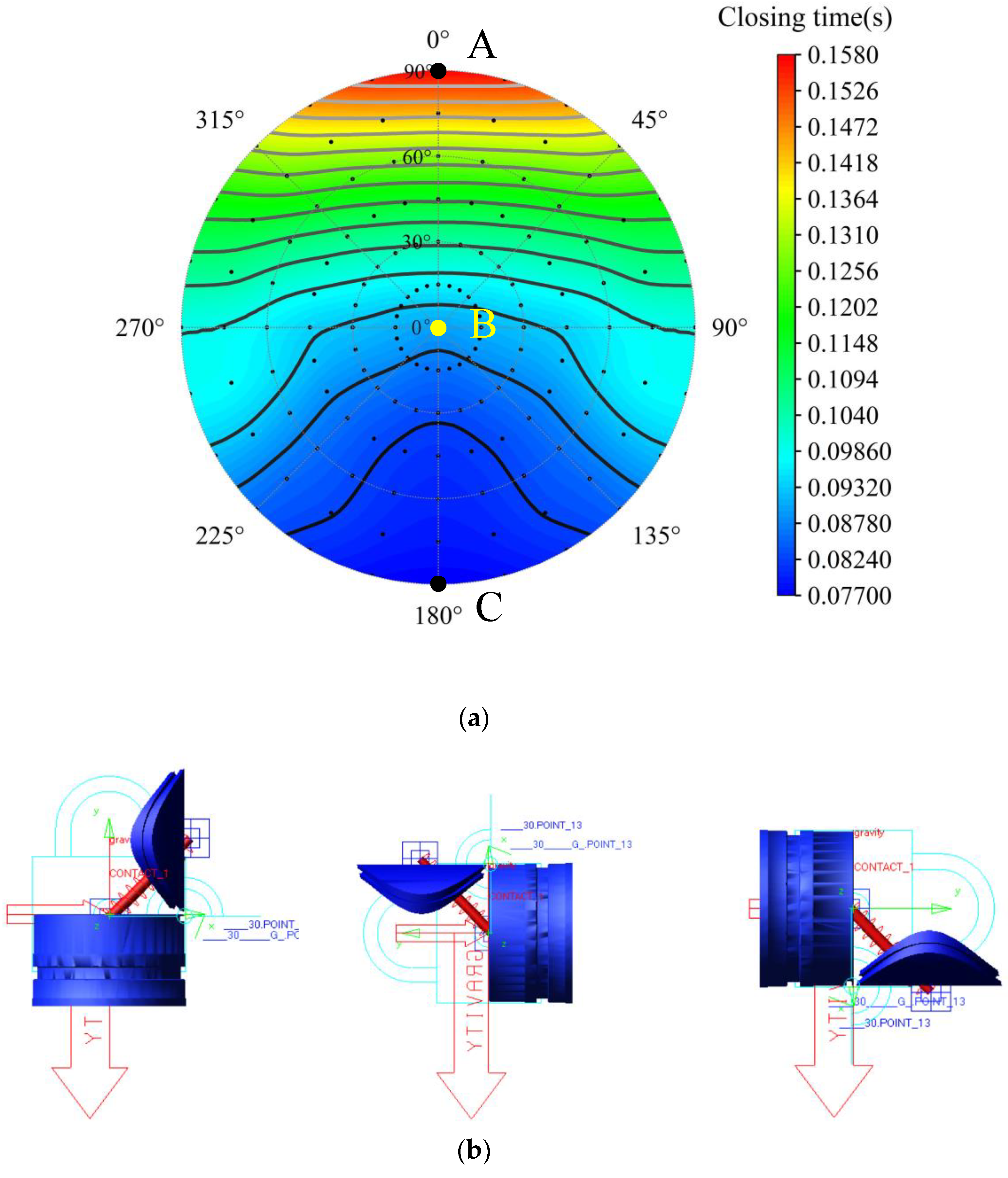
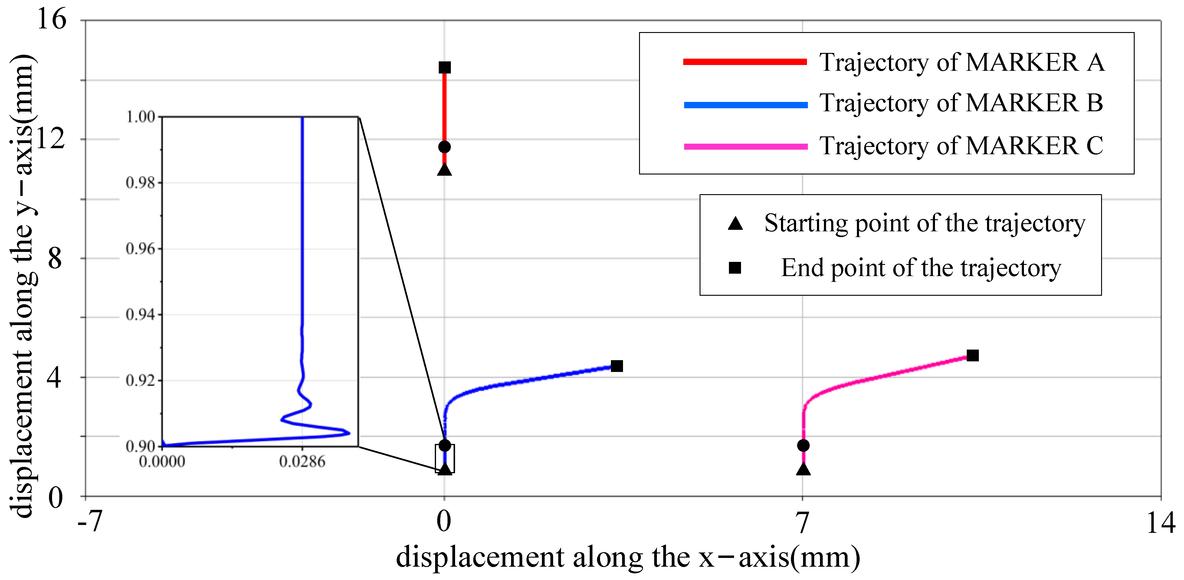
The pressure-holding controller mechanism driven by the elastic force had different closing times at different angles in space, and the closing rules of the valve cover at different azimuth angles were obtained. The two extreme positions with the longest and shortest closing times of the valve cover occurred when the coring device performed horizontal coring, the closing time was the shortest when the pressure-holding controller hinge was at the top, and the closing time was the longest when the pressure-holding controller hinge was at the bottom.
(2)
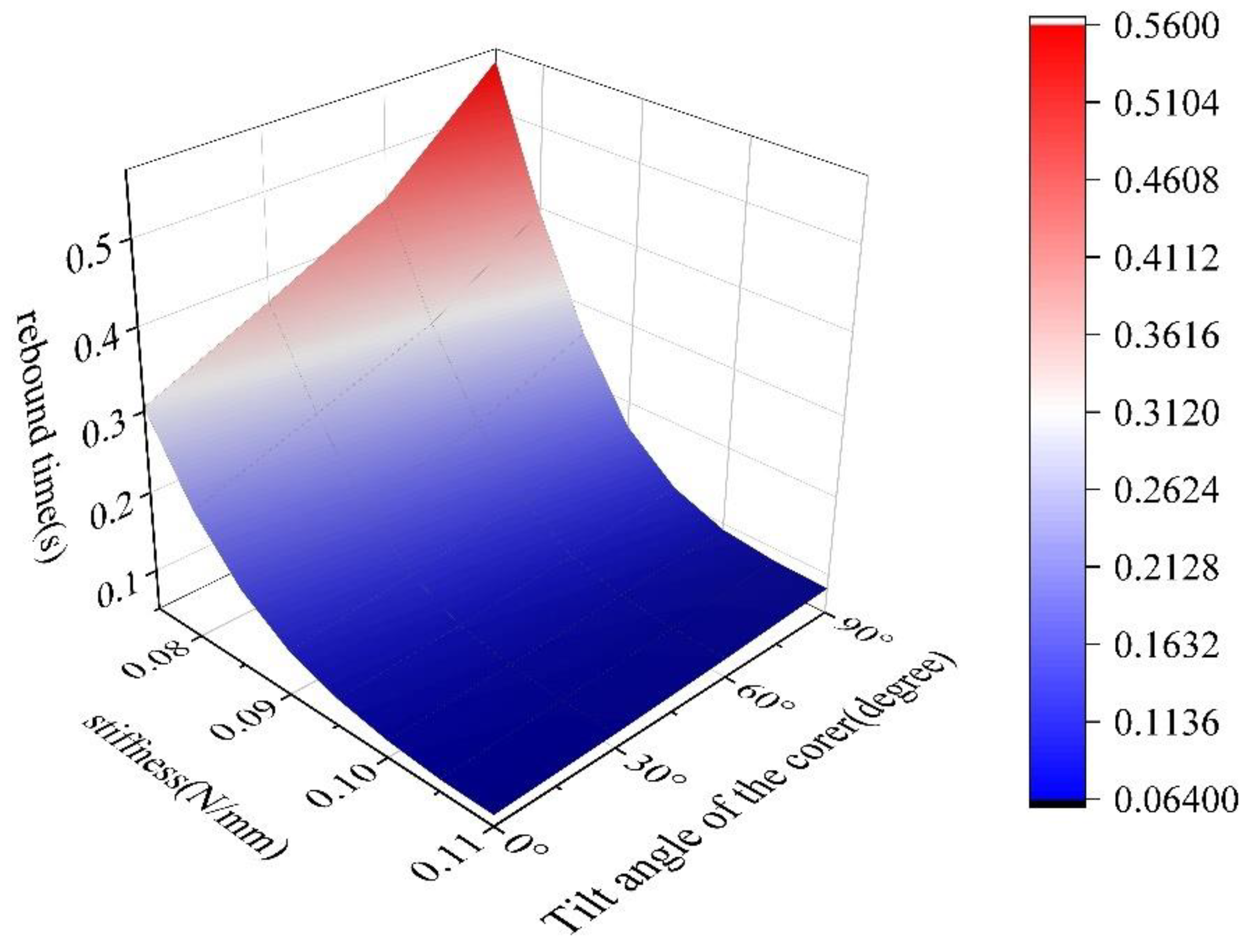
According to the simulation experiments of the spring sleeve springback at several different angles, the selection range of the spring stiffness was determined. In the case of applying fixed initial pressure to the valve cover of the pressure-holding controller, a spring with a small stiffness value should be used. According to the simulation test results, the optimal solution of 0.08 N/mm was obtained.
(3)
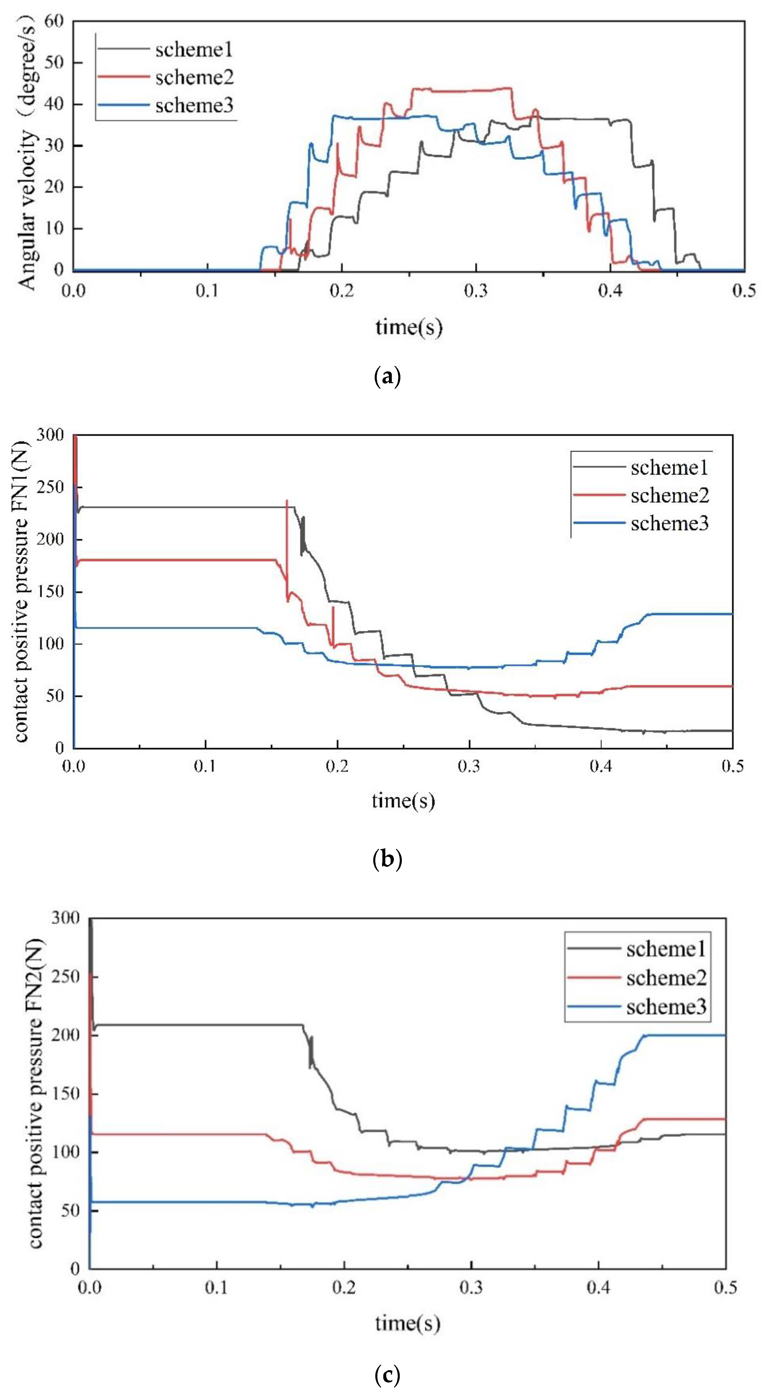
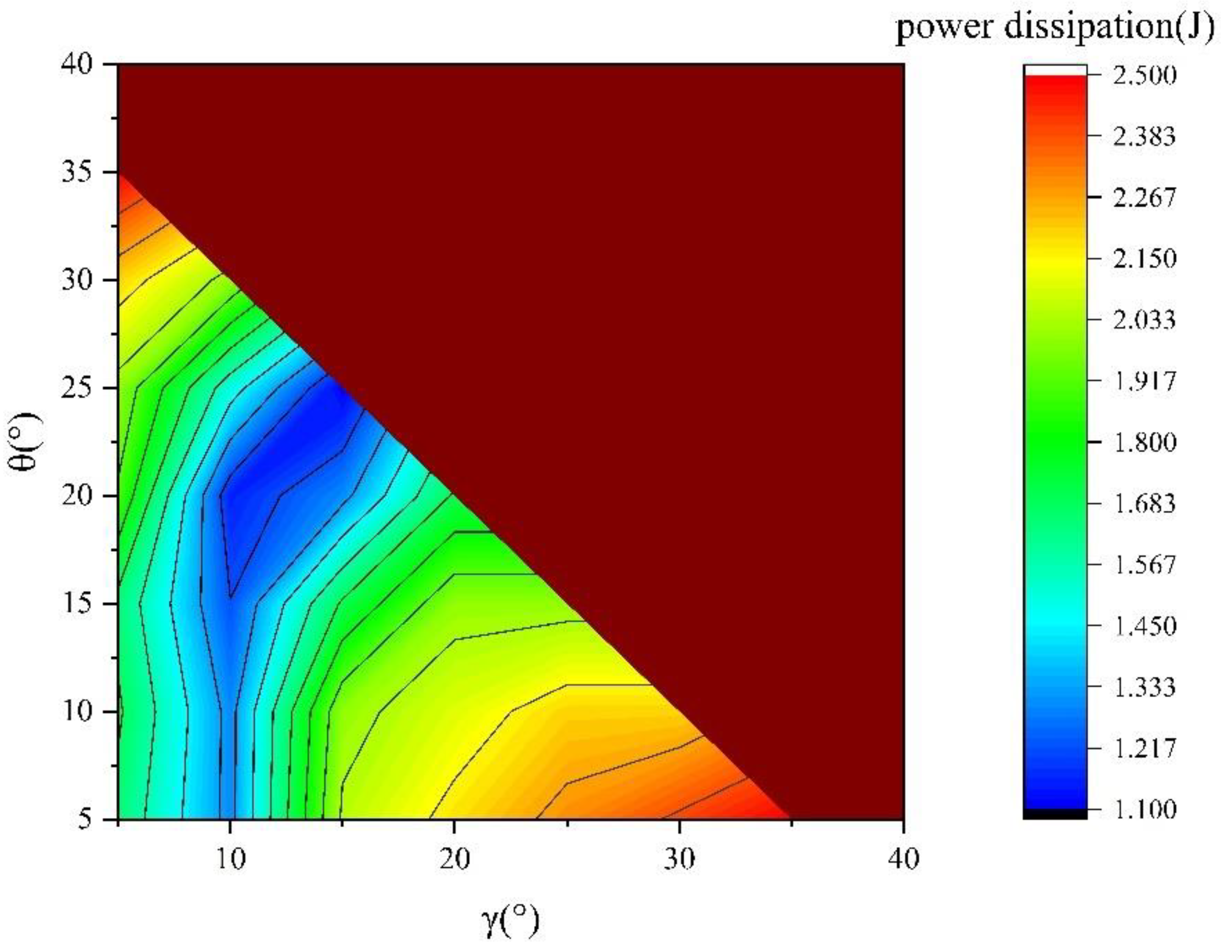
The surface contact mechanics of the trigger mechanism was modeled, the dynamic contact force and dynamic friction force between components under different angle schemes were calculated through numerical simulation, and the energy efficiency of the mechanical system was compared in the three schemes from the perspective of energy input and consumption. scheme 2 was more suitable, and the kinetics was verified and optimized. On this basis, by comparing different combinations of α and β angles, the best set of angle values for γ and θ was optimized, and the key parameters of the contact pin were determined.

Author Contributions

Conceptualization, M.X.; Data curation, M.X., X.Y. and Z.D.; Formal analysis, M.X.; Funding acquisition, Y.L. and L.C.; Investigation, C.F. and D.W. All authors have read and agreed to the published version of the manuscript.

Funding

This research was funded by the major science and technology special project of Sichuan Province “Research on the Key Technologies of Intelligent Process Design of Complex Precision Parts of Electronic Products”, grant number 2020ZDZX0025 and the National Natural Science Foundation of China, grant nos. 51827901 and U2013603.

Institutional Review Board Statement

Not applicable.

Informed Consent Statement

Informed consent was obtained from all subjects involved in the study.

Data Availability Statement

Raw or processed data required to reproduce these findings cannot be shared at this time, as the data also form part of an ongoing study.

Acknowledgments

This study was supported by the major science and technology special project of Sichuan Province “Research on the Key Technologies of Intelligent Process Design of Complex Precision Parts of Electronic Products”, grant number 2020ZDZX0025 and the National Natural Science Foundation of China, grant nos. 51827901 and U2013603. The financial aid is gratefully acknowledged.

Conflicts of Interest

The authors declare that they have no conflict of interest regarding the publication of this paper.

References

  1. Xie, H.-P.; Gao, F.; Ju, Y. Research and development of rock mechanics in deep ground engineering. Chin. J. Rock Mech. Eng. 2015, 34, 2161–2178. [Google Scholar]
  2. Xie, H.P.; Gao, F.; Ju, Y.; Ge, S.R.; Wang, G.F.; Zhang, R.; Gao, M.Z.; Wu, G.; Liu, J.Z. Theoretical and technological conception of the fluidization mining for deep coal resources. J. China Coal. Soc. 2017, 42, 547–556. [Google Scholar]
  3. Gao, M.; Xie, J.; Guo, J.; Lu, Y.; He, Z.; Li, C. Fractal evoluti on and connectivity characteristics of mining-induced crack networks in coal masses at different depths. Geomech. Geophys. Geo-Energy Geo-Resour. 2021, 7, 1. [Google Scholar]
  4. Xie, H.; Ju, Y.; Gao, F.; Gao, M.; Zhang, R. Groundbreaking theoretical and technical conceptualization of fluidized mining of deep underground solid mineral resources. Tunn. Undergr. Space Technol. 2017, 67, 68–70. [Google Scholar] [CrossRef]
  5. Xie, H.; Ju, Y.; Ren, S.; Gao, F.; Liu, J.; Zhu, Y. Theoretical and technological exploration of deep In situ fluidized coal mining. Front. Energy 2019, 13, 603–611. [Google Scholar] [CrossRef]
  6. Xie, H. Research review of the state key research development program of China: Deep rock mechanics and mining theory. J. China Coal Soc. 2019, 44, 1283–1305. [Google Scholar]
  7. Gao, M.-Z.; Wang, M.-Y.; Xie, J. In-situ disturbed mechanical behavior of deep coal rock. J. China Coal Soc. 2020, 45, 2691–2703. [Google Scholar]
  8. Gao, M.; Hao, H.; Xue, S.; Lu, T.; Cui, P.; Gao, Y.; Xie, J.; Yang, B.; Xie, H. Discing behavior and mechanism of cores extracted from Songke-2 well at depths below 4500 m. Int. J. Rock Mech. Min. Sci. 2022, 149, 104976. [Google Scholar]
  9. Gao, M.; Xie, J.; Gao, Y.; Wang, W.; Li, C.; Yang, B.; Liu, J.; Xie, H. Mechanical behavior of coal under different mining rates: A case study from laboratory experiments to field testing. Int. J. Min. Sci. Technol. 2021, 31, 825–841. [Google Scholar] [CrossRef]
  10. Gao, M.Z.; Yang, B.G.; Xie, J.; Ye, S.Q.; Liu, J.J.; Liu, Y.T.; Tang, R.F.; Hao, H.C.; Wang, X.; Wen, X.Y.; et al. The mechanism of microwave rock breaking and its potential application to rock-breaking technology in drilling. Pet. Sci. 2022. [Google Scholar] [CrossRef]
  11. Kvenvolden, K.A.; Cameron, D. Pressure core barrel; Application to the study of gas hydrates. Deep Sea Drilling Project Site 533, Leg 76. Initial. Rep. DSDP 1983, 76, 367–375. [Google Scholar]
  12. Milkov, A.V.; Dickens, G.R.; Claypool, G.E.; Lee, Y.J.; Borowski, W.S.; Torres, M.E.; Xu, W.; Tomaru, H.; Tréhu, A.M.; Schultheiss, P. Co-existence of gas hydrate, free gas, and brine within the regional gas hydrate stability zone at Hydrate Ridge (Oregon margin): Evidence from prolonged degassing of a pressurized core. Earth Planet. Sci. Lett. 2004, 222, 829–843. [Google Scholar] [CrossRef]
  13. Dickens, G.R.; Wallace, P.J.; Paull, C.K.; Borowski, W.S. Detection of methane gas hydrate in the pressure core sampler (PCS): Volume-pressure-time relations during controlled degassing experiments. In Proceedings of the Ocean Drilling Program: Scientific Results; Texas A&M University: College Station, TX, USA, 2000; Volume 164, pp. 113–126. [Google Scholar]
  14. Amann, H.; Hohnberg, H.; Reinelt, R. HYACE-a novel autoclave coring equipment for systematic offshore gashydrate sampling. In Proceedings of the Conference on gas hydrates—noxious substances or resources, Tagung: Gashydrate—Problemstoff/Resource, Clausthal-Zellerfeld, Germany, 6–7 November 1997. [Google Scholar]
  15. Schultheiss, P.; Holland, M.; Humphrey, G. Wireline coring and analysis under pressure: Recent use and future developments of the HYACINTH system. Sci. Drill. 2009, 7, 44–50. [Google Scholar] [CrossRef]
  16. Abegg, F.; Hohnberg, H.J.; Pape, T.; Bohrmann, G.; Freitag, J. Development and application of pressure-core-sampling systems for the investigation of gas-and gas-hydrate-bearing sediments. Deep. Sea Res. Part I Oceanogr. Res. Pap. 2008, 55, 1590–1599. [Google Scholar] [CrossRef]
  17. Qin, H. Research on Low-Disturbing Sampling Theory and Truth-Preserving Technique of Deep-Sea Surface Layer Sediment; Zhejiang University: Hangzhou, China, 2005. [Google Scholar]
  18. Zhu, H.Y.; Liu, Q.Y.; Wong, G.R.; Xiao, X.H.; Zhu, X.H.; Jiang, Z.L.; Zhang, D.Y. A pressure and temperature preservation system for gas-hydrate-bearing sediments sampler. Pet. Sci. Technol. 2013, 31, 652–662. [Google Scholar] [CrossRef]
  19. Luo, Y.; Peng, J.; Sun, M.; Sun, Q.; Ji, T.; Bo, K. An ice-valve-based pressure-coring system for sampling natural hydrate-bearing sediments: Proof-of-concept laboratory studies. J. Nat. Gas Sci. Eng. 2015, 27, 1462–1469. [Google Scholar] [CrossRef]
  20. Zhang, X.; Peng, J.; Sun, M.; Gao, Q.; Wu, D. Development of applicable ice valves for ice-valve-based pressure corer employed in offshore pressure coring of gas hydrate-bearing sediments. Chem. Eng. Res. Des. 2016, 111, 117–126. [Google Scholar] [CrossRef]
  21. Qin, Y.; Yuan, L.; Hu, Q.T.; Ye, J.P.; Hu, A.M.; Shen, B.H.; Cheng, Y.P.; He, X.Q.; Zhang, S.A.; Li, G.F.; et al. Status and development orientation of coal bed methane exploration and development technology in China. Coal Sci. Technol. 2012, 40, 1–6. [Google Scholar]
  22. Wang, X.; Zou, D.; Yang, L.; Liu, A. Design of a pressure preservation coring tool for deep and ultra-deep coalbed methane samples. China Pet. Mach. 2020, 48, 40–45. [Google Scholar]
  23. Wang, F.; Luo, Y.; Liang, Y.; Peng, J.; Li, B. Sampling methane-bearing coal seams by freezing method: Coalbed methane desorption and inhibition characteristics under freezing temperature. Nat. Resour. Res. 2020, 29, 1351–1360. [Google Scholar] [CrossRef]
  24. Gao, M.Z.; Chen, L.; Fan, D.; Yang, M.Q.; Liu, C.; Li, J.N.; Zhao, L.; Tian, D.Z.; Li, C.; Wang, R.Z.; et al. Principle and technology of coring with in-situ pressure and gas maintaining in deep coal mine. J. China Coal Soc. 2021, 46, 885–897. [Google Scholar]
  25. Xie, H.P.; Liu, T.; Gao, M.Z.; Chen, L.; Zhou, H.W.; Ju, Y.; Gao, F.; Peng, X.B.; Li, X.J.; Peng, R.D.; et al. Research on in-situ condition preserved coring and testing systems. Pet. Sci. 2021, 18, 1840–1859. [Google Scholar] [CrossRef]
  26. Li, C.; Xie, H.; Gao, M.; Chen, L.; Zhao, L.; Li, C.; Wu, N.; He, Z.; Li, J. Novel designs of pressure controllers to enhance the upper pressure limit for gas-hydrate-bearing sediment sampling. Energy 2021, 227, 120405. [Google Scholar] [CrossRef]
  27. Xie, H.; Gao, M.; Zhang, R.; Peng, G.; Wang, W.; Li, A. Study on the Mechanical Properties and Mechanical Response of Coal Mining at 1000 m or Deeper. Rock Mech. Rock Eng. 2018, 52, 1475–1490. [Google Scholar] [CrossRef]
  28. Gao, M.Z.; Zhang, J.G.; Li, S.W.; Wang, M.; Wang, Y.W.; Cui, P.F. Calculating changes in fractal dimension of surface cracks to quantify how the dynamic loading rate affects rock failure in deep mining. J. Cent. South Univ. 2020, 27, 3013–3024. [Google Scholar] [CrossRef]
  29. Xie, J.; Gao, M.; Zhang, S.; Fu, C.; Peng, G.; Liu, J. Experimental study on triaxial fracture behavior and energy release law of deep coal under the effect of loading rates. J. Cent. South Univ. (Sci. Technol.) 2021, 52, 2713–2724. [Google Scholar]
  30. Wu, N.; Xie, H.; Chen, L.; Gao, M.; Li, C. Sealing Form and Failure Mechanism of Deep In Situ Rock Core Pressure-Maintaining Controller. Geofluids 2020, 2020, 8892720. [Google Scholar] [CrossRef]
  31. Liu, P.; Song, W.; Jiang, Q.; Li, X. Sealing performance of O-ring in deep sea high pressure environment. Chin. Hydraul. Pneum. 2017, 66–70. [Google Scholar] [CrossRef]
  32. Ji, J. Research on Sealing and Friction Characteristics of O-Seal Ring. Ph.D. Thesis, Harbin Institute of Technology, Harbin, China, 2015. [Google Scholar]
  33. Zheng, E.; Zhu, R.; Zhu, S.; Lu, X. A study on dynamics of flexible multi-link mechanism including joints with clearance and lubrication for ultra-precision presses. Nonlinear Dyn. 2016, 83, 137–159. [Google Scholar] [CrossRef]
  34. Li, J.; Yan, S.; Guo, F.; Guo, P. Effects of damping, friction, gravity, and flexibility on the dynamic performance of a deployable mechanism with clearance. Proc. Inst. Mech. Eng. Part C J. Mech. Eng. Sci. 2013, 227, 1791–1803. [Google Scholar] [CrossRef]
  35. Zheng, E.; Zhou, X. Modeling and simulation of flexible slider-crank mechanism with clearance for a closed high speed press system. Mech. Mach. Theory 2014, 74, 10–30. [Google Scholar] [CrossRef]
  36. Rong, X.; Li, Y.; Ruan, J.; Li, B. Design and simulation for a hydraulic actuated quadruped robot. J. Mech. Sci. Technol. 2012, 26, 1171–1177. [Google Scholar] [CrossRef]
  37. Khemili, I.; Romdhane, L. Dynamic analysis of a flexible slider–crank mechanism with clearance. Eur. J. Mech. A/Solids 2008, 27, 882–898. [Google Scholar] [CrossRef]
  38. Sharf, I.; Zhang, Y.N. A contact force solution for non-colliding contact dynamics simulation. Multibody Syst. Dyn. 2006, 16, 263–290. [Google Scholar] [CrossRef]
Figure 1. Physical diagram of pressure-holding controller based on principle of geometric intersection of cylinder and cone.
Applsci 12 04961 g001
Figure 2. (a) Cross-sectional view of pressure-maintaining corer structure; (b) sectional view of pressure-maintaining coring process.
Applsci 12 04961 g002
Figure 3. Fitting curve of viscous resistance growth of a nitrile rubber with relative sliding velocity under the condition of a specific compression ratio and surface roughness.
Applsci 12 04961 g003
Figure 4. Example of contact mechanics model based on impact function.
Applsci 12 04961 g004
Figure 5. Geometric design of contact pin and force state during action.
Applsci 12 04961 g005
Figure 6. Three-dimensional design diagram of trigger mechanism installed in corer.
Applsci 12 04961 g006
Figure 7. Mechanism model of trigger mechanism under ADAMS/View.
Applsci 12 04961 g007
Figure 8. (a) Distribution law of valve cover closing time for pressure-holding controller under different azimuth deflection angles. (b) Closing simulation model of pressure-holding controller at three typical azimuth angles of A, B, and C (Figure 6a).
Applsci 12 04961 g008
Figure 9. Springback time law for different stiffness levels corresponding to sleeves under several inclination angles.
Applsci 12 04961 g009
Figure 10. Motion trajectory of typical points A, B, and C on control pin mechanism.
Applsci 12 04961 g010
Figure 11. Parameter characteristics during flipping process of contact pin. (a) Flipping angular velocity of contact pin along its axis of rotation. (b,c) Time domain variation curves of contact positive pressures FN1 and FN2.
Applsci 12 04961 g011
Figure 12. Distribution law of frictional energy dissipation (Q) of contact pin under different combinations of angles γ and θ.
Applsci 12 04961 g012
Table 1. Definition of relationship between motion and force of each component in ADAMS trigger mechanism.
ComponentCore Barrel BootSleeveContact PinOuter Tube
Core barrel boot
SleeveTranslational joint
Contact pinContact forceRevolute joint, Contact force
Outer tubeNoneTranslational joint (with friction), spring forceContact force (with Coulomb friction)
Table 2. ADAMS simulation parameters of the trigger mechanism.
Elastic modulus E (GPa)220
Poisson’s ratio   μ 0.27
Static friction coefficient μ 0 0.3
Coefficient of kinetic friction μ s 0.18
Contact stiffness K 1 (N/mm) 6.5 × 10 5
Contact stiffness K 2 (N/mm) 6.5 × 10 5
Drive speed v 1 (mm/s)100
Publisher’s Note: MDPI stays neutral with regard to jurisdictional claims in published maps and institutional affiliations.

