
An Improved Ground Moving Target Parameter Estimation and Imaging Method for Multichannel High Resolution SAR

 ,
,  , and
, and
Abstract
:1. Introduction
2. Signal Model
3. The Proposed Method
3.1. Rcmc Based on Hough-SOKT
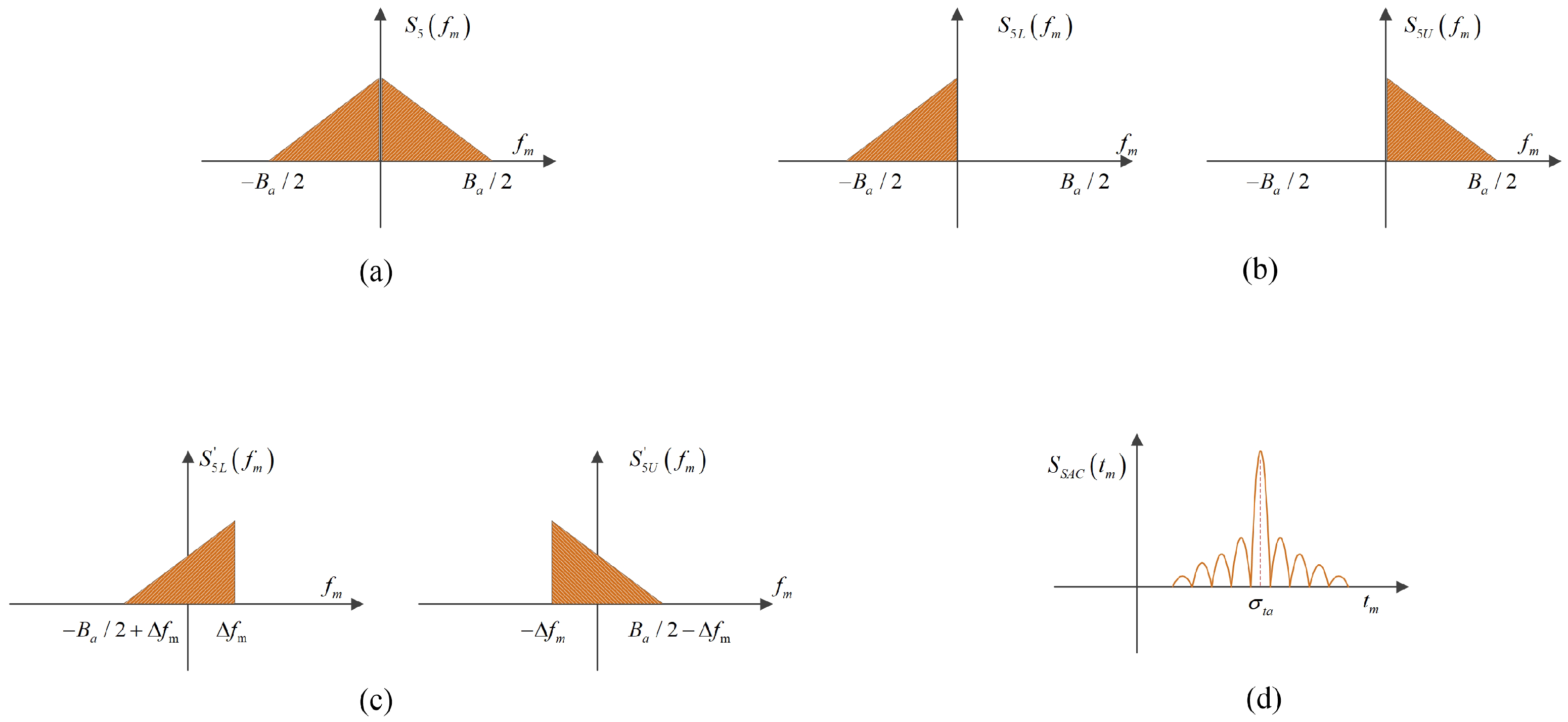
3.2. Construction of DCCF
3.3. Parameter Estimation Based on SAC Algorithm and 2D-FFT
3.4. Focused Imaging and Relocation
3.5. Computational Complexity Analysis
4. Algorithm Implementation
5. Experimental Results
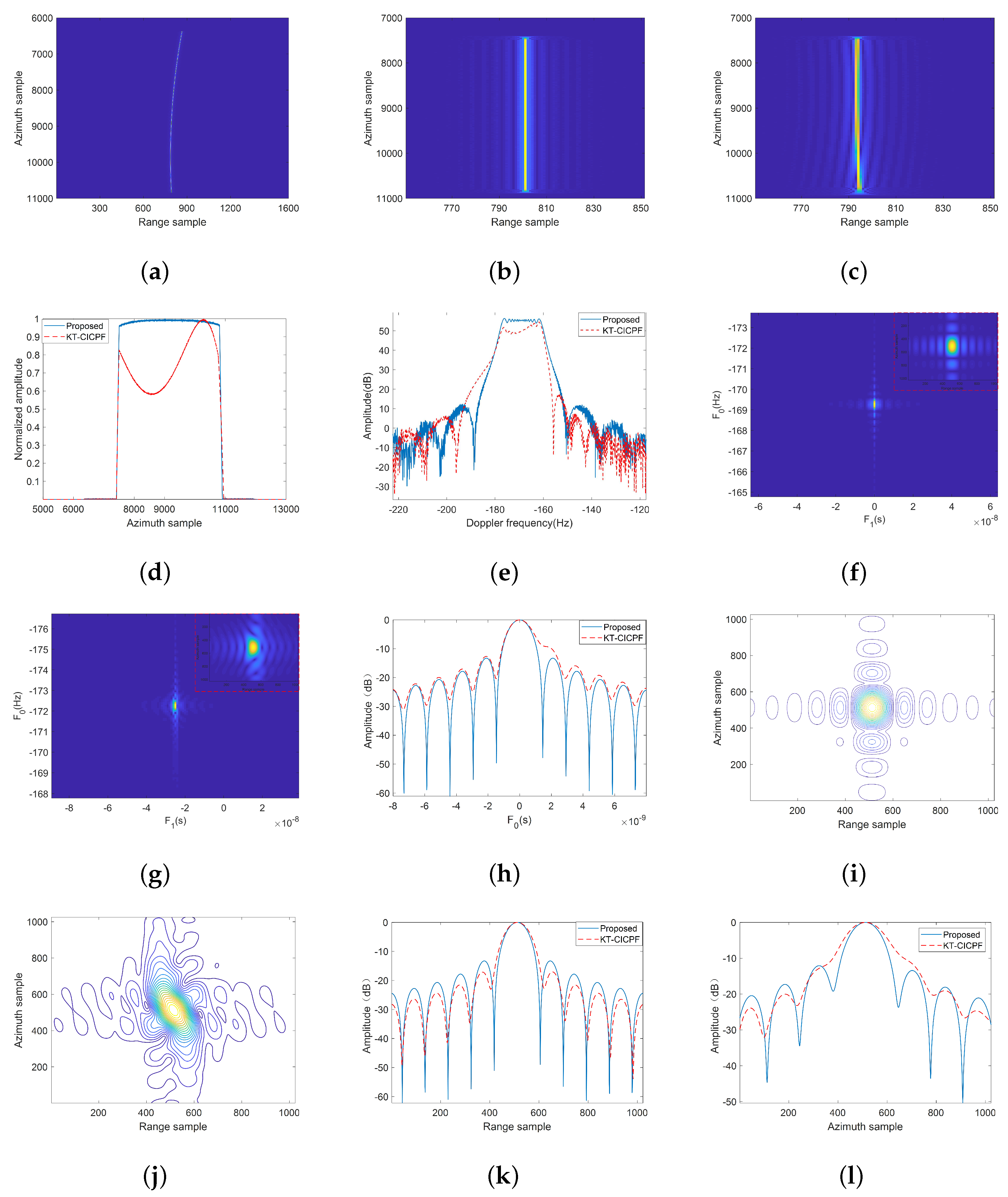
5.1. Simulation Experiment
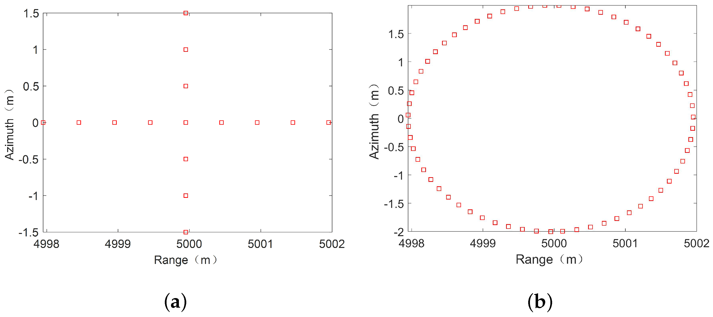
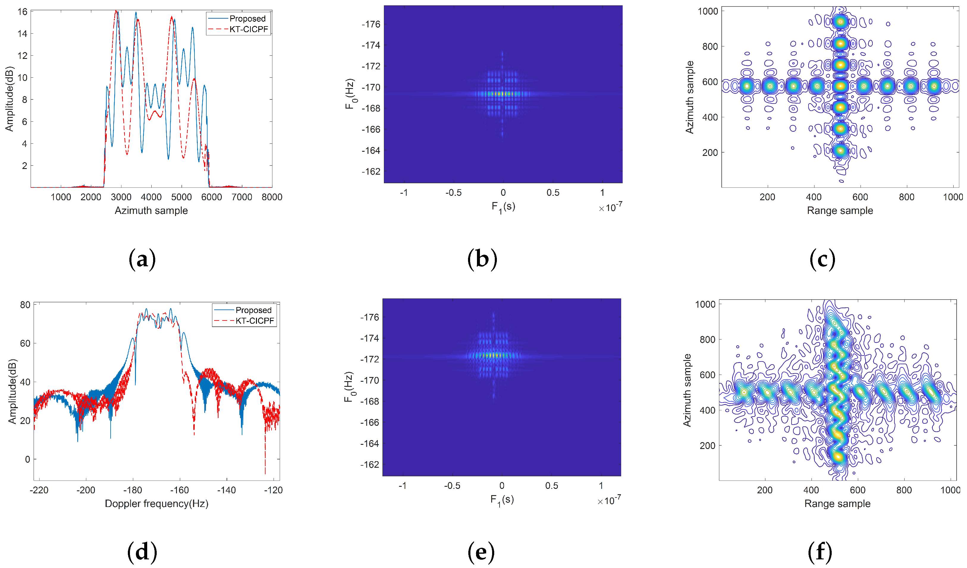
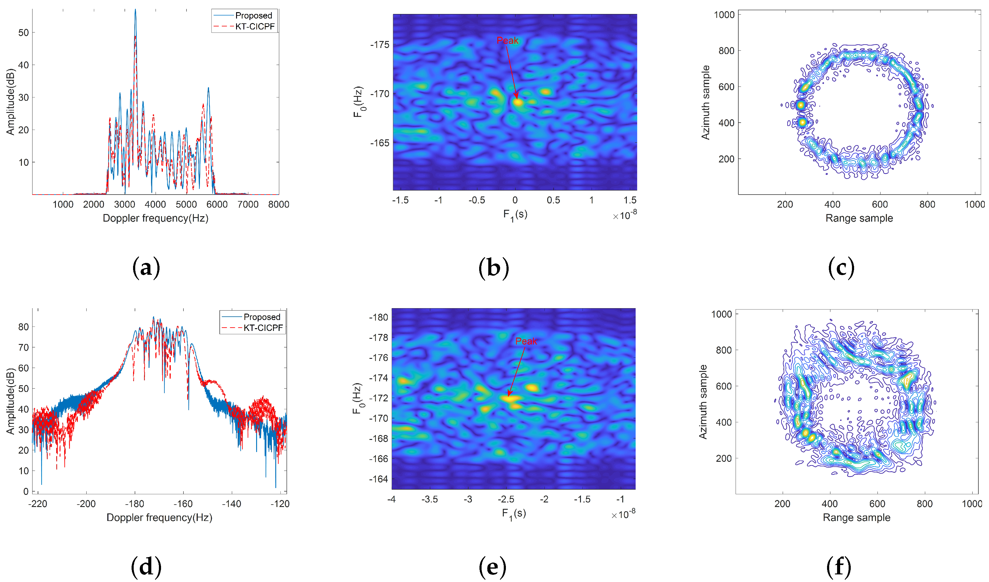
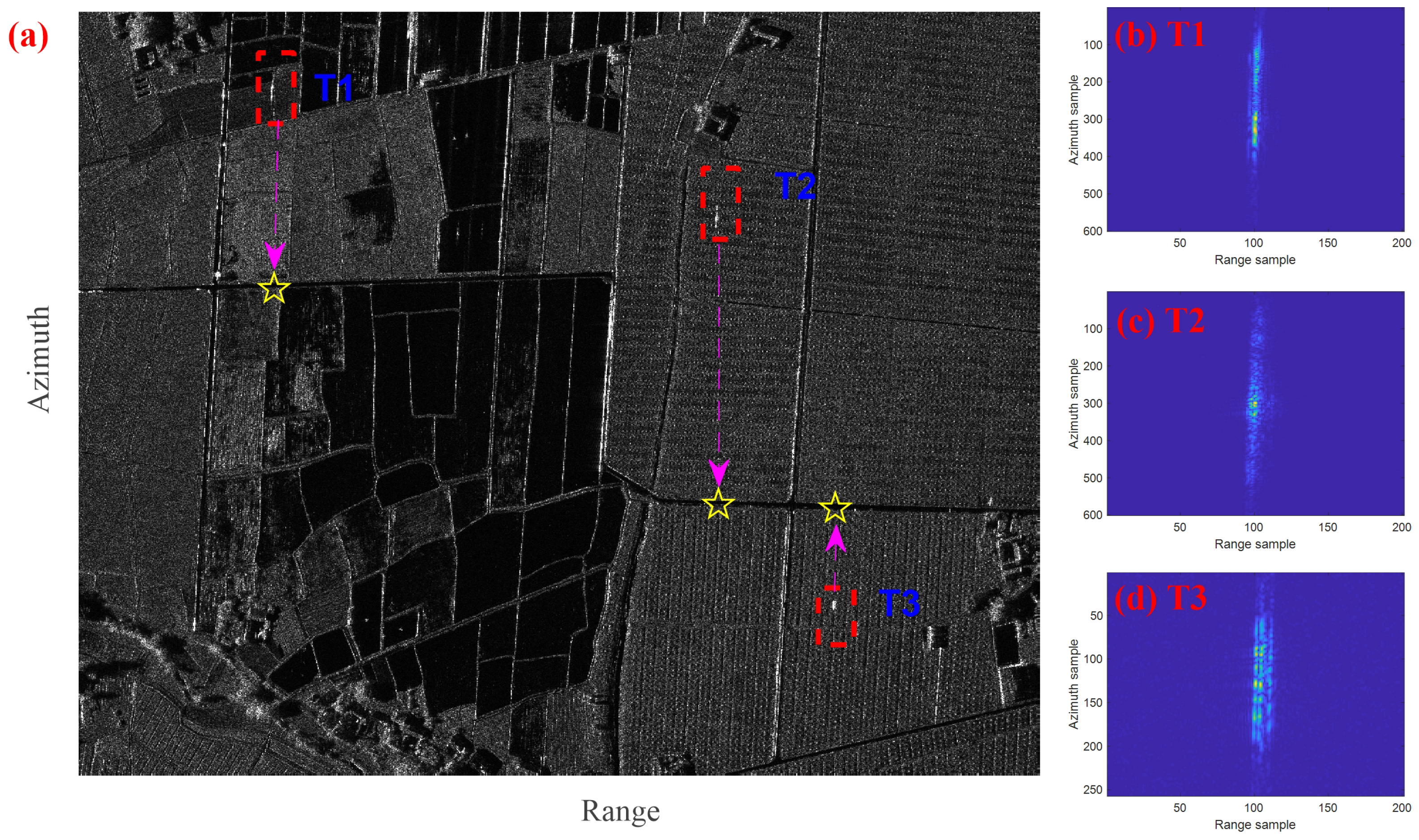
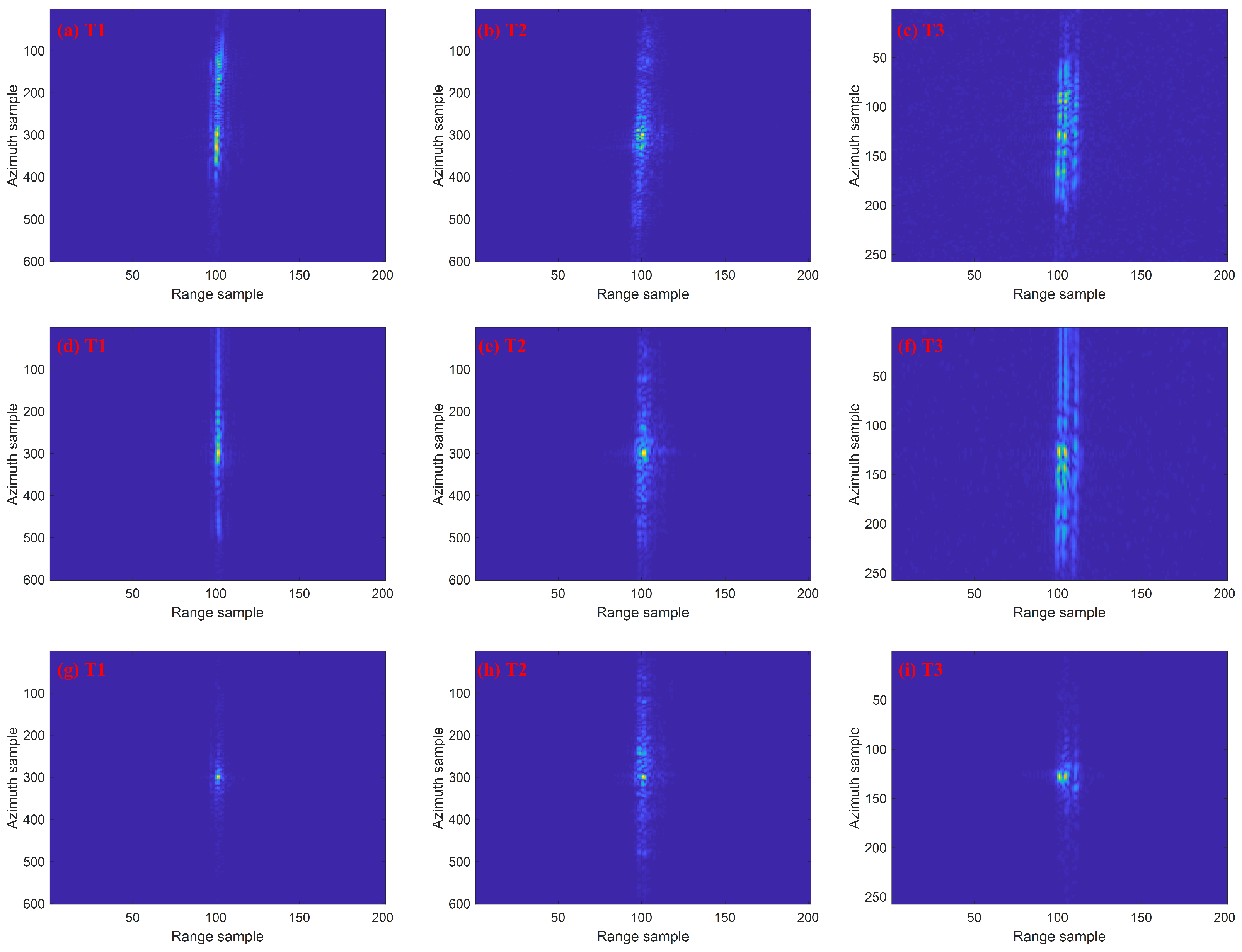
5.2. Measured Experiment
6. Conclusions
Author Contributions
Funding
Institutional Review Board Statement
Informed Consent Statement
Data Availability Statement
Acknowledgments
Conflicts of Interest
References
- Budillon, A.; Gierull, C.H.; Pascazio, V.; Schirinzi, G. Along-Track Interferometric SAR Systems for Ground-Moving Target Indication: Achievements, Potentials, and Outlook. IEEE Geosci. Remote Sens. Mag. 2020, 8, 46–63. [Google Scholar] [CrossRef]
- Huang, P.; Zhang, X.; Zou, Z.; Liu, X.; Liao, G.; Fan, H. Road-Aided Along-Track Baseline Estimation in a Multichannel SAR-GMTI System. IEEE Geosci. Remote Sens. Lett. 2021, 18, 1416–1420. [Google Scholar] [CrossRef]
- Gierull, C.H. Closed-Form Expressions for InSAR Sample Statistics and Its Application to Non-Gaussian Data. IEEE Trans. Geosci. Remote Sens. 2021, 59, 3967–3980. [Google Scholar] [CrossRef]
- Wang, W.; An, D.; Luo, Y.; Zhou, Z. The Fundamental Trajectory Reconstruction Results of Ground Moving Target From Single-Channel CSAR Geometry. IEEE Trans. Geosci. Remote Sens. 2018, 56, 5647–5657. [Google Scholar] [CrossRef]
- Li, Y.; Wang, Y.; Liu, B.; Zhang, S.; Nie, L.; Bi, G. A New Motion Parameter Estimation and Relocation Scheme for Airborne Three-Channel CSSAR-GMTI Systems. IEEE Trans. Geosci. Remote Sens. 2019, 57, 4107–4120. [Google Scholar] [CrossRef]
- Zhang, X.; Yang, C.; Lin, Q.; Zhang, X. Efficient Parameters Estimation Methods for Radar Moving Targets Without Searching. IEEE Access 2020, 8, 41351–41361. [Google Scholar] [CrossRef]
- Lan, Y.; Li, Z.; Qu, J.; Wu, J.; Yang, J. A Fast Doppler Parameters Estimation Method for Moving Target Imaging Based ON 2D-FFT. In Proceedings of the IGARSS 2018—2018 IEEE International Geoscience and Remote Sensing Symposium, Valencia, Spain, 22–27 July 2018; pp. 589–592. [Google Scholar] [CrossRef]
- Zeng, C.; Li, D.; Luo, X.; Song, D.; Liu, H.; Su, J. Ground Maneuvering Targets Imaging for Synthetic Aperture Radar Based on Second-Order Keystone Transform and High-Order Motion Parameter Estimation. IEEE J. Sel. Top. Appl. Earth Obs. Remote Sens. 2019, 12, 4486–4501. [Google Scholar] [CrossRef]
- Huang, P.; Xia, X.G.; Liao, G.; Yang, Z. Ground Moving Target Imaging Based on Keystone Transform and Coherently Integrated CPF With a Single-Channel SAR. IEEE J. Sel. Top. Appl. Earth Obs. Remote Sens. 2017, 10, 5686–5694. [Google Scholar] [CrossRef]
- Liu, Z.; Li, Z.; Huang, C.; Wu, J.; Yang, J. Bistatic Forward-Looking SAR KDCT-FSFT-Based Refocusing Method for Ground Moving Target With Unknown Curve Motion. IEEE J. Sel. Top. Appl. Earth Obs. Remote Sens. 2020, 13, 4848–4858. [Google Scholar] [CrossRef]
- Ran, L.; Liu, Z.; Zhang, L.; Xie, R.; Li, T. Multiple Local Autofocus Back-Projection Algorithm for Space-Variant Phase-Error Correction in Synthetic Aperture Radar. IEEE Geosci. Remote Sens. Lett. 2016, 13, 1241–1245. [Google Scholar] [CrossRef]
- Hui, Z.; Fengjun, Z.; Jian, Y. SAR Accelerating Moving Target Parameter Estimation and Imaging Based on Three-order Polynomial Fourier Transform. J. Electron. Inf. Technol. 2016, 38, 8. [Google Scholar] [CrossRef]
- Cristallini, D.; Pastina, D.; Colone, F.; Lombardo, P. Efficient Detection and Imaging of Moving Targets in SAR Images Based on Chirp Scaling. IEEE Trans. Geosci. Remote Sens. 2013, 51, 2403–2416. [Google Scholar] [CrossRef]
- Kong, L.; Li, X.; Cui, G.; Yi, W.; Yang, Y. Coherent Integration Algorithm for a Maneuvering Target With High-Order Range Migration. IEEE Trans. Signal Process. 2015, 63, 4474–4486. [Google Scholar] [CrossRef]
- Mu, H.; Zhang, Y.; Ding, C.; Jiang, Y.; Er, M.H.; Kot, A.C. DeepImaging: A Ground Moving Target Imaging Based on CNN for SAR-GMTI System. IEEE Geosci. Remote Sens. Lett. 2021, 18, 117–121. [Google Scholar] [CrossRef]
- Fienup, J. Detecting moving targets in SAR imagery by focusing. IEEE Trans. Aerosp. Electron. Syst. 2001, 37, 794–809. [Google Scholar] [CrossRef]
- Perry, R.; DiPietro, R.; Fante, R. SAR imaging of moving targets. IEEE Trans. Aerosp. Electron. Syst. 1999, 35, 188–200. [Google Scholar] [CrossRef]
- Huang, P.; Xia, X.G.; Liao, G.; Yang, Z.; Zhou, J.; Liu, X. Ground Moving Target Refocusing in SAR Imagery Using Scaled GHAF. IEEE Trans. Geosci. Remote Sens. 2018, 56, 1030–1045. [Google Scholar] [CrossRef]
- Yang, J.; Zhang, Y. An Airborne SAR Moving Target Imaging and Motion Parameters Estimation Algorithm With Azimuth-Dechirping and the Second-Order Keystone Transform Applied. IEEE J. Sel. Top. Appl. Earth Obs. Remote Sens. 2015, 8, 3967–3976. [Google Scholar] [CrossRef]
- Tang, X.; Zhang, X.; Shi, J.; Wei, S. A Novel Ground Moving Target Radial Velocity Estimation Method for Dual-Beam Along-Track Interferometric Sar. In Proceedings of the IGARSS 2020—2020 IEEE International Geoscience and Remote Sensing Symposium, Waikoloa, HI, USA, 26 September–2 October 2020; pp. 389–392. [Google Scholar] [CrossRef]
- Tian, J.; Cui, W.; Xia, X.G.; Wu, S.L. Parameter Estimation of Ground Moving Targets Based on SKT-DLVT Processing. IEEE Trans. Comput. Imaging 2016, 2, 13–26. [Google Scholar] [CrossRef] [Green Version]
- Chao, W.; Yanfei, W.; Chang, L.; Bidan, L. A New Approach to Range Cell Migration Correction for Ground Moving Targets in High-resolution SAR System Based on Parameter Estimation. J. Radars 2019, 8, 64–72. [Google Scholar] [CrossRef]
- Zhang, X.; Liao, G.; Zhu, S.; Yang, D.; Xu, J. A geometry-based hough transform estimation for radial velocity of moving target using single antenna SAR. In Proceedings of the 2014 XXXIth URSI General Assembly and Scientific Symposium (URSI GASS), Beijing, China, 16–23 August 2014; pp. 1–4. [Google Scholar] [CrossRef]
- Chen, S.; Yuan, Y.; Zhang, S.; Zhao, H.; Chen, Y. A New Imaging Algorithm for Forward-Looking Missile-Borne Bistatic SAR. IEEE J. Sel. Top. Appl. Earth Obs. Remote Sens. 2016, 9, 1543–1552. [Google Scholar] [CrossRef]
- Huang, P.; Liao, G.; Yang, Z.; Xia, X.G.; Ma, J.; Zheng, J. Ground Maneuvering Target Imaging and High-Order Motion Parameter Estimation Based on Second-Order Keystone and Generalized Hough-HAF Transform. IEEE Trans. Geosci. Remote Sens. 2017, 55, 320–335. [Google Scholar] [CrossRef]
- Wu, Y.-F.; Sun, G.-C.; Xing, M.-D.; Bao, Z. An Improved Doppler Rate Estimation Approach Based on the Range-Keystone Transform. J. Electron. Inf. Technol. 2013, 35, 7. [Google Scholar] [CrossRef]
- Liao, Y.; Wang, W.Q.; Liu, Q.H. Two-Dimensional Spectrum for Circular Trace Scanning SAR Based on an Implicit Function. IEEE Geosci. Remote Sens. Lett. 2016, 13, 887–891. [Google Scholar] [CrossRef]
- Wang, R.; Deng, Y.K.; Loffeld, O.; Nies, H.; Walterscheid, I.; Espeter, T.; Klare, J.; Ender, J.H.G. Processing the Azimuth-Variant Bistatic SAR Data by Using Monostatic Imaging Algorithms Based on Two-Dimensional Principle of Stationary Phase. IEEE Trans. Geosci. Remote Sens. 2011, 49, 3504–3520. [Google Scholar] [CrossRef]
- Xu, J.; Xia, X.G.; Peng, S.B.; Yu, J.; Peng, Y.N.; Qian, L.C. Radar Maneuvering Target Motion Estimation Based on Generalized Radon-Fourier Transform. IEEE Trans. Signal Process. 2012, 60, 6190–6201. [Google Scholar] [CrossRef]
- Zhu, S.; Liao, G.; Yang, D.; Tao, H. A New Method for Radar High-Speed Maneuvering Weak Target Detection and Imaging. IEEE Geosci. Remote Sens. Lett. 2014, 11, 1175–1179. [Google Scholar] [CrossRef]
- Dong, Q.; Wang, B.; Xiang, M.; Wang, Z.; Wang, Y.; Song, C. A Novel Detection Scheme in Image Domain for Multichannel Circular SAR Ground-Moving-Target Indication. Sensors 2022, 22, 2596. [Google Scholar] [CrossRef]
- Liu, B.; Yin, K.; Li, Y.; Shen, F.; Bao, Z. An Improvement in Multichannel SAR-GMTI Detection in Heterogeneous Environments. IEEE Trans. Geosci. Remote Sens. 2015, 53, 810–827. [Google Scholar] [CrossRef]
- Fu, K. Aircraft Reconstruction in High-Resolution SAR Images Using Deep Shape Prior. ISPRS Int. J. Geo-Inf. 2017, 6, 330. [Google Scholar] [CrossRef] [Green Version]
- Zibo, Z.; Chaowei, Z.; Saiqiang, X. Feature Extraction of Rotor Blade Targets Based on Phase Compensation in a Passive Bistatic Radar. J. Radars 2021, 10, 15. [Google Scholar] [CrossRef]


| Methods | Computational Complexity |
|---|---|
| GRFT method [29] | |
| 2-D frequency matched filtering [30] | |
| Hough-GHAF method [25] | |
| KDCT-FSFT method [10] | |
| Proposed method |
| Parameter | Value | Parameter | Value |
|---|---|---|---|
| Carrier frequency | 10 GHz | Range sampling frequency | 2000 MHz |
| Platform velocity | 100 m/s | Pulse duration time | 1 s |
| Range bandwidth | 1000 Mhz | Center slant range | 5 Km |
| Pulse repetition frequency | 1200 Hz | Synthetic aperture time | 5 s |
| 3 m/s | −1 m/ | ||
| 4 m/s | 2 m/ |
| Parameter | True | Proposed Method | KT-CICPF | ||
|---|---|---|---|---|---|
| Estimate | Erro% | Estimate | Erro% | ||
| −3.00000000 | −2.99384938 | 0.20502050 | −3.01689870 | 0.56329000 | |
| 1.42160000 | 1.42090117 | 0.04915745 | 1.32186099 | 7.01596862 | |
| −0.01864704 | −0.01868167 | 0.18571902 | −0.01828961 | 1.916818969 | |
| Method | Parameter | Resolution (m) | PSLR (dB) | ISLR (dB) |
|---|---|---|---|---|
| Theoretical value | Range | 0.1329 | −13.27 | −10.24 |
| Azimuth | 0.1256 | −13.27 | −10.24 | |
| Proposed method | Range | 0.1338 | −13.26 | −10.21 |
| Azimuth | 0.1288 | −12.05 | −9.70 | |
| KT-CICPF | Range | 0.1463 | −17.03 | −14.46 |
| Azimuth | 0.1589 | −18.77 | −16.66 |
| Parameter | Value | Parameter | Value |
|---|---|---|---|
| Wave band | X | Pulse duration time | 5 s |
| Range bandwidth | 1800 MHz | Pulse repetition frequency | 2000 Hz |
| Range sampling frequency | 2000 MHz | Center slant range | 7 Km |
| Target velocity | <3 m/s | Synthetic aperture time | 5 s |
| Target | Resolution (m) | Proposed Method | KT-CICPF |
|---|---|---|---|
| T1 | Range | 0.0918 | 0.0913 |
| Azimuth | 0.2317 | 0.6078 | |
| T2 | Range | 0.0926 | 0.0924 |
| Azimuth | 0.2590 | 0.4479 | |
| T3 | Range | 0.0867 | 0.0824 |
| Azimuth | 0.2143 | 0.3383 |
Publisher’s Note: MDPI stays neutral with regard to jurisdictional claims in published maps and institutional affiliations. |
© 2022 by the authors. Licensee MDPI, Basel, Switzerland. This article is an open access article distributed under the terms and conditions of the Creative Commons Attribution (CC BY) license (https://creativecommons.org/licenses/by/4.0/).
Share and Cite
Dong, Q.; Wang, B.; Xiang, M.; Jiao, Z.; Wang, Z.; Song, C. An Improved Ground Moving Target Parameter Estimation and Imaging Method for Multichannel High Resolution SAR. Appl. Sci. 2022, 12, 4934. https://doi.org/10.3390/app12104934
Dong Q, Wang B, Xiang M, Jiao Z, Wang Z, Song C. An Improved Ground Moving Target Parameter Estimation and Imaging Method for Multichannel High Resolution SAR. Applied Sciences. 2022; 12(10):4934. https://doi.org/10.3390/app12104934
Chicago/Turabian StyleDong, Qinghai, Bingnan Wang, Maosheng Xiang, Zekun Jiao, Zhongbin Wang, and Chong Song. 2022. "An Improved Ground Moving Target Parameter Estimation and Imaging Method for Multichannel High Resolution SAR" Applied Sciences 12, no. 10: 4934. https://doi.org/10.3390/app12104934
APA StyleDong, Q., Wang, B., Xiang, M., Jiao, Z., Wang, Z., & Song, C. (2022). An Improved Ground Moving Target Parameter Estimation and Imaging Method for Multichannel High Resolution SAR. Applied Sciences, 12(10), 4934. https://doi.org/10.3390/app12104934