Article

Study on the Restraint Effect of Isolation Pile on Surface Settlement Trough Induced by Shield Tunnelling

1
School of Civil Engineering, Changsha University of Science & Technology, Changsha 410114, China
2
School of Civil Engineering, Changsha University, Changsha 410022, China
3
Shanghai Harbour Foundations Construction Group Ltd., Shanghai 200092, China
*
Authors to whom correspondence should be addressed.
Appl. Sci. 2022, 12(10), 4845; https://doi.org/10.3390/app12104845
Submission received: 20 April 2022 / Revised: 4 May 2022 / Accepted: 9 May 2022 / Published: 11 May 2022
(This article belongs to the Special Issue Advanced Underground Space Technology)

Abstract

:
Isolation piles are widely used to control the influence of shield tunnelling on adjacent buildings as an effective protective measure. However, the restraint effect of isolation pile on surface settlement trough is rarely explored from the internal mechanism. Firstly, the restraint mechanism of isolation piles is investigated from the pile-soil-tunnel interaction mechanism. Secondly, based on the Melan solution and the Loganathan formula, the analytical solution of surface settlement trough under the influence of adjacent isolation piles is derived. Thirdly, in order to satisfy the engineering analysis scale and reflect the friction characteristics between isolation pile and soil particles simultaneously, the FDM-DEM coupling technique is introduced to establish a numerical model including discrete medium and continuum medium. Finally, the applicability and reliability of the analytical solution and the FDM-DEM coupling numerical solution are verified by comparing field measured data. The results indicate that the surface settlement trough under the influence of isolation piles will have an asymmetric distribution. Surface settlement tends to develop more to the opposite side of the tunnel when isolation piles are pre-installed on one side. The findings of the study have substantial theoretical significance and engineering reference value.

1. Introduction

In recent years, the increasing urban population density and residents’ travel demand have brought huge traffic load to the limited ground space. The underground railway constructed by shield tunnelling has advantages of large unit transport, fast transport speed, high punctuality, and almost no influence from external weather, which can effectively mitigate the ground traffic congestion and gradually become the first choice for residents to travel in the urban area. However, shield tunnelling often needs to pass through a huge number of existing pile foundations at a close distance due to the large quantity of infrastructure in metropolitan areas [1,2,3,4,5]. Tunnelling-induced ground surface settlement, inclination, and discontinuous displacement could affect or even damage adjacent superstructures. The isolation pile between the existing pile and the tunnel is widely proven as an efficient protective measure for controlling the displacement of building’s pile foundation induced by shield tunnelling [6,7,8,9].
In general, the surface settlement trough induced by shield tunnelling is approximately a Gaussian distribution in transverse direction [10]. However, when the isolation pile is pre-installed, the stiffness of the isolation pile is substantially larger than that of the surrounding soil, resulting in an asymmetrical distribution of surface settlement trough. Currently, various scholars have focused on this issue and conducted several studies. Fantera et al. [11] first presented a plane strain finite element analysis, in which a continuous diaphragm made by adjacent panels was established to evaluate the effects of various geometrical and mechanical parameters. Ding et al. [12] held the opinion that surface settlement trough based on Peck formula was not reasonable. Surface settlement trough will present cork distribution, skewed distribution, and normal distribution according to the scope of the disturbance when shield tunnelling passes through adjacent buildings. Huang et al. [13] highlighted that the surface settlement trough curve presented a ‘hanging phenomenon’ near the adjacent pile foundation. The existence of pile foundation will restraint the displacement of soil around pile induced by shield tunnelling. Rampello et al. [14] presented a numerical study to evaluate the efficiency of different schemes of embedded barriers. The results illustrated that the diaphragm wall could reduce both surface settlements and curvature of surface settlement trough beyond its location. Masini et al. [15] conducted a series of soil-structure interaction finite element analyses to evaluate the efficiency of a barrier made of a line of bored piles, comparing with field monitoring data from a test site in Rome and simple empirical equations. Franza et al. [16] proposed a three-dimensional linear elastic prediction method to evaluate the protective action of pile walls against surface and subsurface ground movements due to tunnel excavation. The barrier efficiency in reducing settlements is explored by comparing pile walls and diaphragm walls. Sun et al. [17] established three-dimensional finite element models to analyze the effects of different pile diameters and different distance between pile and tunnel on the surface settlement trough. An asymmetric skewness distribution curve was proposed by fitting the simulated data. Cao et al. [18] proposed an elastic solution for evaluating tunneling-induced vertical ground displacements due to the restraint of embedded isolation piles. Parametric analysis indicates that parameters associated with the isolation pile and the soil have significant influence on the surface settlement troughs and the barrier efficiency. To sum up, the above theoretical studies, numerical simulations, centrifugal tests, and field measured data adequately describe the restraint effect of isolation piles. However, most scholars performed parametric analyses, but did not investigate the underlying reasons for impact on the surface settlement trough induced by the pile-soil-tunnel interaction mechanism.
In view of the aforementioned issues, it is of great significance to study the restraint mechanism of isolation pile on soil displacement induced by shield tunnelling, which can help us better predict the surface settlement trough and accurately evaluate the protection effect of isolation pile on the adjacent buildings.
The outline of this paper is as follows: firstly, the Loganathan formula [19] based on virtual image principle is adopted to calculate the surface settlement trough without isolation piles. On this basis, Melan solution [20,21] in the semi-infinite plane based on elasticity is introduced to derive the ultimate surface settlement trough from the perspective of negative friction of pile edge. Secondly, an engineering case is found in the Changsha Metro Line 5 from East Laodong Road Station to Huaya Station, where shield tunnelling passes through Huaya International Hotel at a close distance. Thirdly, a two-dimensional numerical model is established based on FDM-DEM coupling, with the constraint effect of the isolation pile on the surface settlement trough reflected through the friction effect between particles and the wall. Finally, the applicability and reliability of the analytical and numerical solutions are verified by comparing field measured data, which has significant engineering guiding reference in analyzing such projects.

2. Restraint Mechanism of Isolation Pile

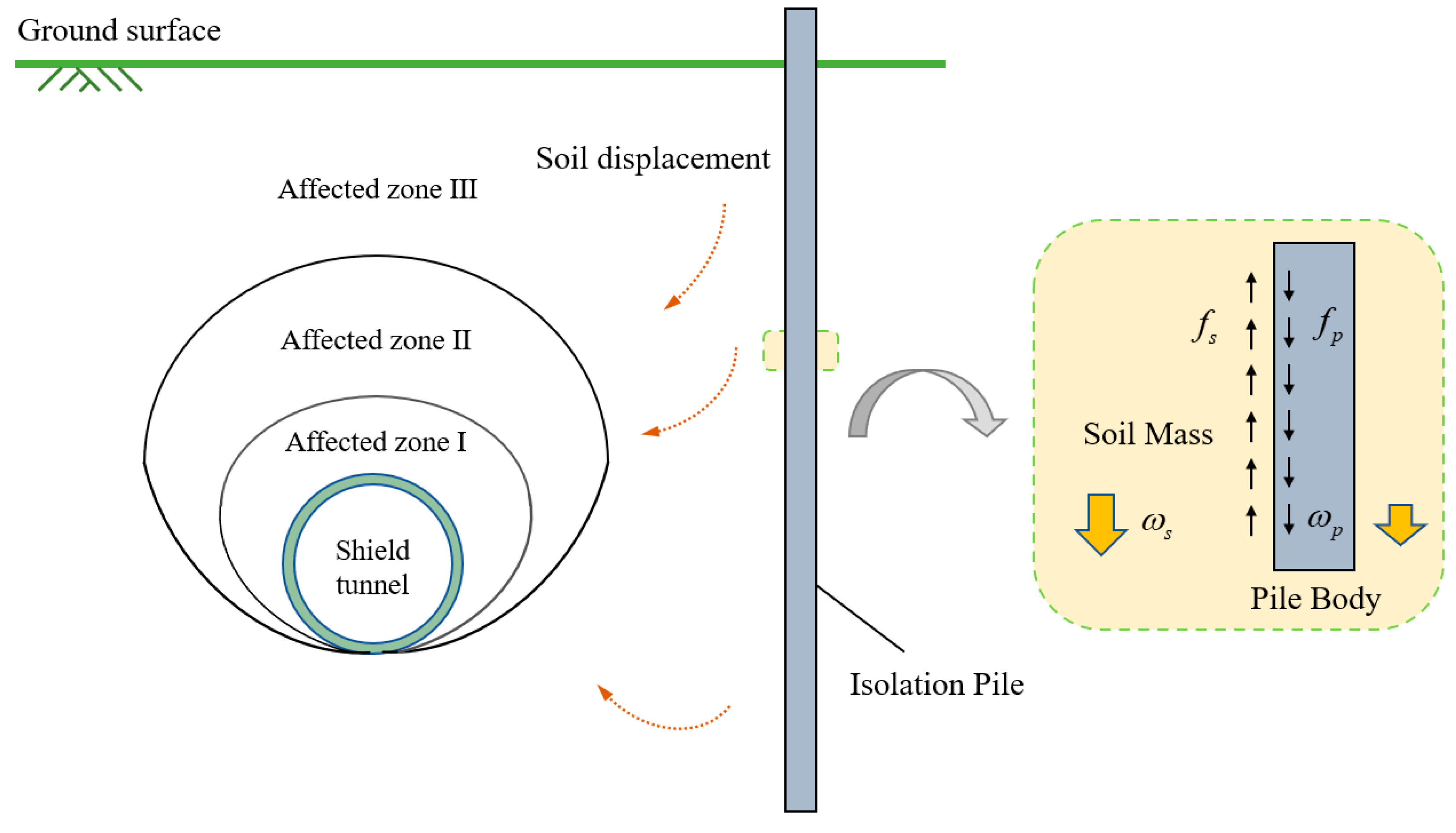
2.1. Pile-Soil-Tunnel Interaction Mechanism
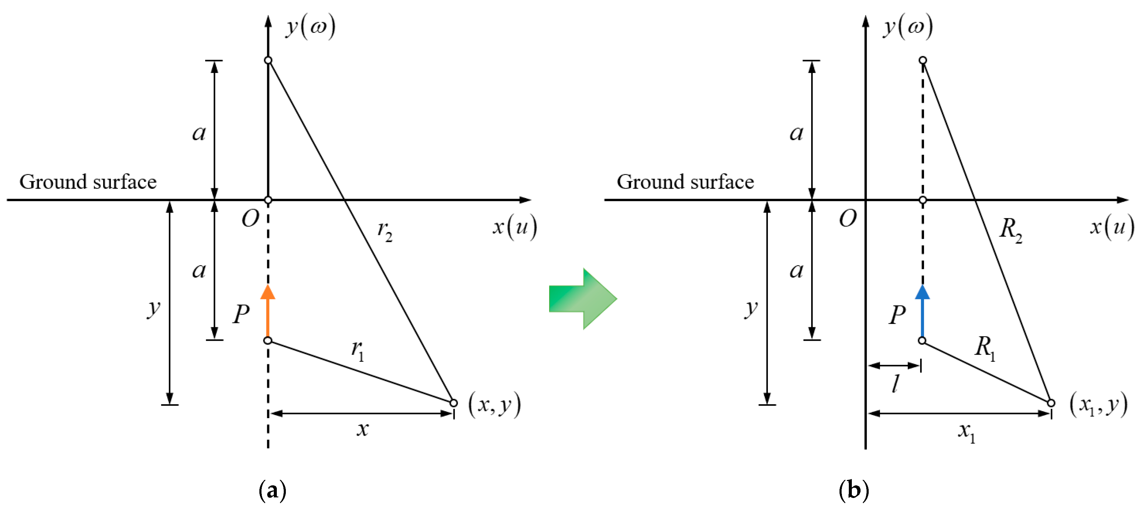
Ground loss is an inevitable consequence of shield tunnelling. The ground loss in the disturbed zone will cause discontinuous settlement due to stress redistribution, resulting in soil particle wedge-caulking. According to the affecting degree of stratum disturbance induced by shield tunnelling, the strata perpendicular to the direction of shield tunnelling can be separated into three zones. As shown in Figure 1, they are, respectively, affected zone Ⅰ (strong disturbance zone), affected zone Ⅱ (medium disturbance zone), and affected zone Ⅲ (weak disturbance zone). The larger the disturbance, the greater the soil displacement toward the excavation area.
In Figure 1, ωs is the vertical displacement of soil, ωp is the vertical displacement of isolation pile, fs is the restraint force of soil on pile side, fp is the negative friction of isolation pile. As the vertical displacement of soil induced by tunnelling is larger than that of adjacent isolation pile, the surface of isolation pile will be affected by negative friction downward. According to the law of action and reaction, the soil around the isolation pile is subjected to upward by restraint force, resulting in the inconsistent surface settlement on both sides of the pile body.

2.2. Melan Solution

Melan first presented an elastic mechanics solution for a vertical line loading beneath the surface of a semi-infinite plane [20,21]. However, Melan’s initial solution is merely a stress solution and does not satisfy the compatibility equation of elastic mechanics, which makes Melan solution less commonly utilized to guide engineering practice. On the basis of Melan solution, Verruijt and Booker [22] further derived the analytical solution of vertical displacement, in which a vertical line loading beneath the surface of a semi-infinite plane. In this study, Melan solution is introduced to analyze the restraint effect of adjacent isolation pile on the surface settlement trough through coordinate transformation. The calculation diagram of Melan solution is shown in Figure 2.

2.3. Analytical Solution
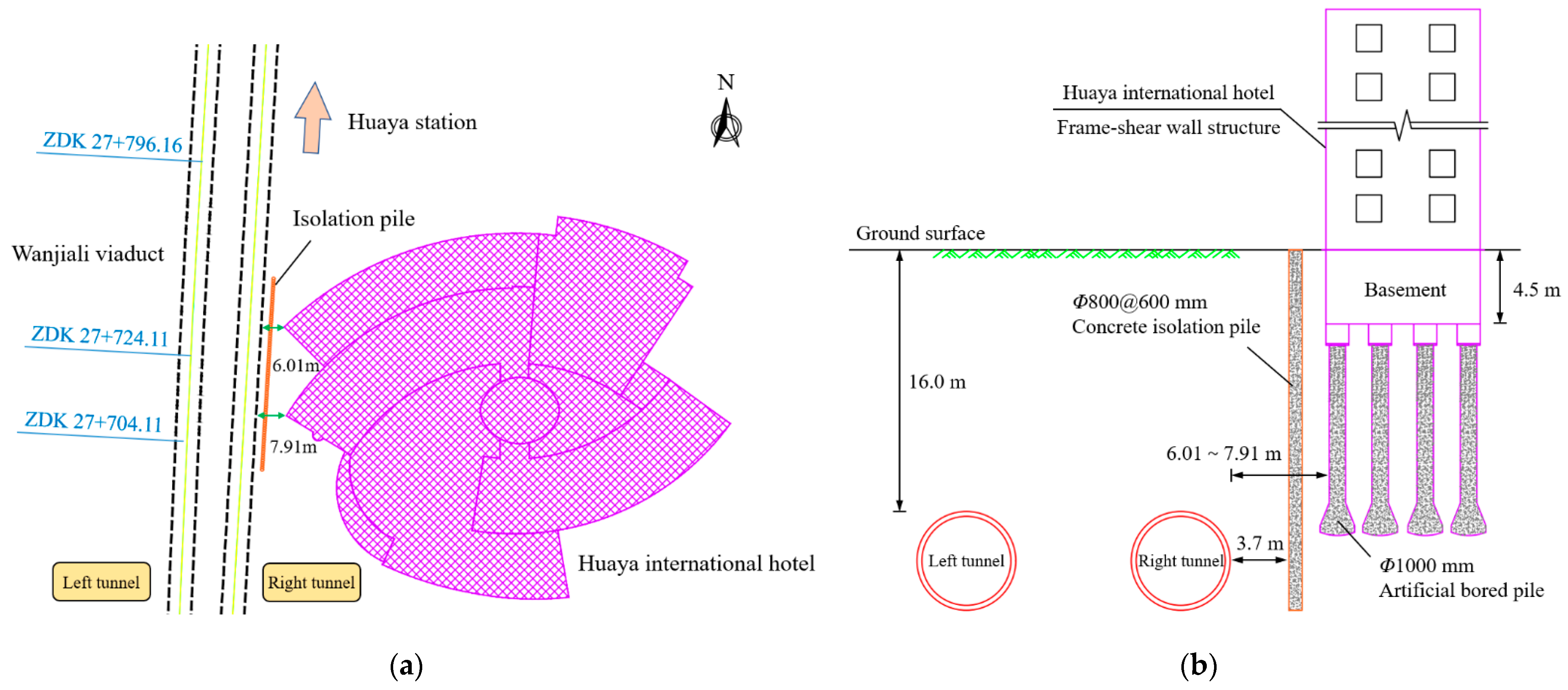
In this study, the Loganathan formula [19] is adopted to calculate the surface settlement trough without considering the influence of isolation piles. The vertical displacement of soil can be obtained by:
ω L = R 2 { y h x 2 + ( y h ) 2 + ( 3 4 μ ) ( y + h ) x 2 + ( y + h ) 2 2 y [ x 2 ( y + h ) 2 ] [ x 2 + ( y + h ) 2 ] 2 } 4 g R + g 2 4 R 2 exp [ 1.38 x 2 ( h + R ) 2 0.69 y 2 h 2 ]
where ωL is the vertical displacement of soil induced by shield tunnelling without considering the effect of isolation pile (m), h is the depth of the tunnel axis from the ground surface (m), R is the radius of the tunnel (m), g is the gap parameter, x is the lateral distance from the tunnel axis (m), and y is the depth measured from the ground surface (m).
The vertical displacement of soil for a vertical line loading upward beneath the surface of a semi-infinite plane can be calculated by:
ω M = P 8 π G ( 1 μ ) [ ( 3 4 μ ) ln r 1 r 2 + x 2 r 1 2 x 2 r 2 2 ] P ( 1 μ ) π G ln r 1 + P ( y a ) 2 2 π G r 1 2 + P y a [ x 2 ( y a ) 2 ] 4 π G ( 1 μ ) r 1 4 + u 0
where ωM is the vertical displacement of soil caused by the vertical line load (m), P is the vertical line load per unit length (N/m), G is the shear modulus (N/m2), a is the distance from load application point to ground surface (m), u0 is the constant related to rigid body displacement (m), μ is the Poisson’s ratio, r1 is the distance from the observation point to load application point (m), and r2 is the distance from the observation point to load application image point (m).
r1 and r2 can be expressed as:
r 1 = [ x 2 + ( y a ) 2 ] 1 2
r 2 = [ x 2 + ( y + a ) 2 ] 1 2
Equation (2) can be expressed as Equation (5) after coordinate transformation.
ω M = P 8 π G ( 1 μ ) [ ( 3 4 μ ) ln R 1 R 2 + x 1 2 R 1 2 x 1 2 R 2 2 ] P ( 1 μ ) π G ln R 1 + P ( y a ) 2 2 π G R 1 2 + P y a [ x 1 2 ( y a ) 2 ] 4 π G ( 1 μ ) R 1 4 + u 0
where ωM is the vertical displacement of soil caused by restraint effect of isolation pile (m), x1 is the lateral distance from the tunnel axis after coordinate transformation (m), x1 = xl, l is the distance from isolation pile to tunnel axis (m), R1 is the distance from the observation point to load application point after coordinate transformation (m), and R2 is the distance from the observation point to load application image point after coordinate transformation (m).
R1 and R2 can be expressed as:
R 1 = [ ( x 1 l ) 2 + ( y a ) 2 ] 1 2
R 2 = [ ( x 1 l ) 2 + ( y + a ) 2 ] 1 2
The vertical displacement of soil induced by shield tunnelling considering the restraint effect of adjacent isolation pile can be expressed as Equation (8). When y → 0, the results degenerate into surface settlement trough.
ω = ω L + ω M

3. Case Study

As shown in Figure 3, a case study is found in the Changsha Metro Line 5 from East Laodong Road Station to Huaya Station. The interval right tunnel passes through Huaya International Hotel at a close distance between mileage YDK27 + 680 m and YDK27 + 750 m. The building is a frame-shear wall structure of 3–22 stories, with a basement of 1 story. The foundations are made of artificial bored piles with a diameter of 1000 mm. The pile toe enters a 1.5 m thick bearing layer. The minimum horizontal distance between the pile foundation of adjacent building and the tunnel edge is approximately 6.01 m. The thickness of soil in this section is about 16.0 m, and the stratum is mainly weathered conglomerate.
Before shield tunnelling to the Huaya International Hotel, the concrete piles with 800 mm diameter and 600 mm spacing are pre-installed in a single row to isolate and protect the building near the right tunnel side. Isolation piles made of C30 underwater concrete (strength is equivalent to ordinary C35 concrete) are installed from the ground surface to the bottom of the tunnel. At this time, the shortest distance between the edge of right tunnel and the isolation pile is merely 3.7 m.
In order to study the restraint effect of isolation pile on surface settlement trough induced by shield tunnelling, the surface settlement observation points were monitored by precision leveling instrument and indium steel ruler. The monitoring holes were drilled by 140 mm crystal drill.

4. FDM-DEM Coupling Model

The discrete element method (DEM) decomposes the soil mass into a series of particles in space, enabling for the calculation of friction between particles and walls. This study focuses on the restraint effect caused by friction between isolation piles and soil, which is suitable for simulation by discrete element method. However, the computational efficiency of the discrete element method is far lower than that of the continuum approaches, such as the finite element method (FEM) and the finite difference method (FDM). Therefore, the modeling size of DEM will be severely constrained. In order to satisfy the requirement of engineering analysis scale and reflect micro mechanical properties, this study introduces the FDM-DEM coupling technique [23,24,25,26] to realize the efficient coupling analysis between discrete medium and continuum medium.

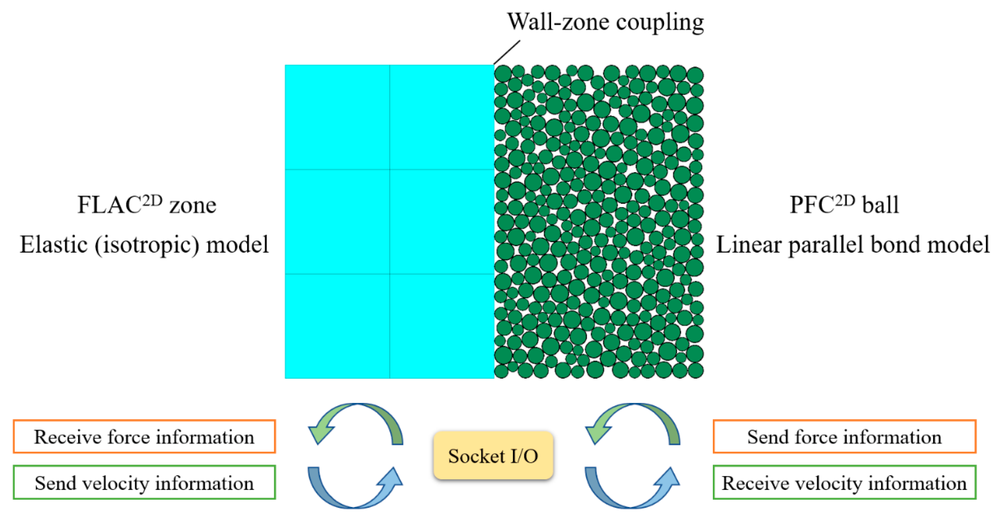
4.1. FDM-DEM Coupling Technique

The FDM-DEM coupling mechanism based on FLAC2D and PFC2D is shown in Figure 4 for the plane strain problem. The force-displacement criterion is applied to each contact in each PFC2D cycle. Particle motion is controlled according to Newton’s second law. The positions of particles and walls are constantly updated. The unbalanced force on coupled wall-zone will be transmitted to FLAC2D through the embedded Socket I/O interface. After obtaining the new stress and force, the new velocity and displacement will be calculated by balance equation. The node displacement in the coupled area will be transformed into a new displacement boundary condition through the Socket I/O interface again, so that the particles in the discrete domain will generate displacement. The cycle calculations will be carried out in turn.

4.2. Numerical Model

According to the case mentioned above, the FDM-DEM coupling model is shown in Figure 5. The model has a length of 60 m and a height of 40 m. The discrete domain is 20 m in length and 18 m in height. The radius of shield tunnel is 3.0 m. The distance between the isolation pile and the right tunnel is 3.7 m. The length of the isolation pile is 22 m, and the width is 0.8 m. Ground loss induced by shield tunnelling is simulated by controlling walls shrinkage. The ground loss rate is estimated to be 2.5% based on feedback from field construction parameters. Isotropic elastic constitutive model is adopted in FLAC2D zone. In order to accurately simulate the characteristics of rock and soil, linear parallel bond constitutive model is adopted in PFC2D ball. Macroscopic and microscopic physical and mechanical parameters of soil are shown in Table 1.

5. Analysis and Verification

5.1. Results of Analytical Solution

The surface settlement trough calculated by the analytical solution proposed in this study is shown in Figure 6. The friction of adjacent isolation piles on the surrounding soil restricts the surface settlement trough to some extent, resulting in an asymmetric distribution of the ultimate surface settlement trough. According to the results of the Melan solution, it can be found that the restraint effect becomes more obvious with the shortening of the distance from the isolation pile. The surface settlement decreases remarkably near the isolation pile. If the isolation pile is located on the right side of the tunnel, the surface settlement trough shows the characteristics of left low and right high. The analytical solution proposed in this study reveals the reasons of asymmetric surface settlement trough deformation resulting from the pile-soil-tunnel interaction mechanism.

5.2. Results of FDM-DEM Coupling

Figure 7 presents the contours of soil displacement around the tunnel induced by shield tunnelling with and without isolation piles. It can be seen that the affected zone of soil displacement above the top of the tunnel is wider and the displacement variation is more uniform without isolation pile. The affected zone of soil displacement above the tunnel top is restricted under the influence of isolation piles. The soil around the pile is restrained to some extent under the impact of friction, which blocks soil displacement to progress to the other side of the isolation pile.
The comparisons of surface settlement trough calculated by FDM-DEM coupling is shown in Figure 8. There is an asymmetric phenomenon in the surface settlement trough without isolation piles due to the randomness of particle generation and particle distribution after initial stress balance. The overall results are highly similar to those calculated by Loganathan formula. The maximum surface settlement with isolation piles is slightly less than that without isolation piles. In this case, the maximum surface settlement without isolation piles is 8.937 mm, and the maximum surface settlement with isolation piles is 8.225 mm, with a decrease of 7.96%. The numerical results indicate that if isolation piles are pre-installed on the right side of the tunnel, the soil displacement will be restrained on the right side, but the soil displacement will transfer to the side without pile.

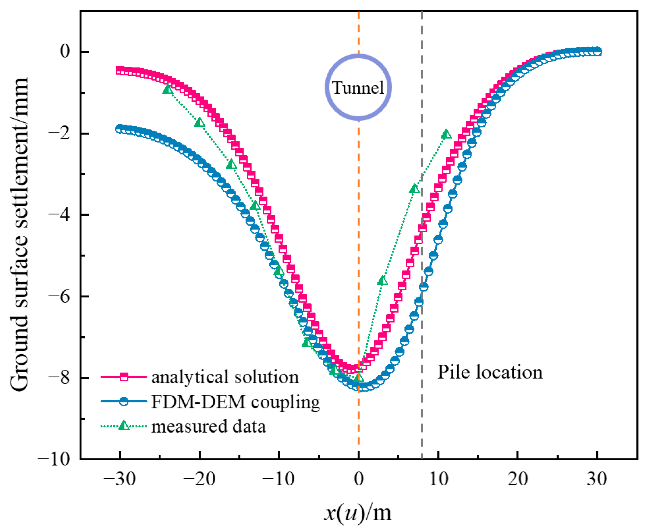
5.3. Comparison with Field Measured Ddata

The comparison results of the analytical solution, FDM-DEM coupling, and field measured data are shown in Figure 9. The results indicate that the analytical solution proposed in this study and the numerical solution based on FDM-DEM coupling are both in good agreement with the field measured data. The numerical solution based on FDM-DEM coupling is slightly larger than the measured data when analyzing the surface settlement on the left side of the tunnel. The displacement of surface settlement trough at x = −30 m is −1.893 mm, which is larger than −0.459 mm calculated by analytical solution. The reason for this phenomenon is that in the FDM-DEM coupling calculation, the calculation mode of the continuum medium needs to be adjusted to the ‘model largestrain’ mode. The results of soil displacement are more significantly affected by the parameters, and the calculation results may be larger than the measured data. This finding clearly indicates that when isolation piles are pre-installed on one side of the tunnel, surface settlement tends to develop more on the opposite side. In the meantime, the surface settlement trough could be discontinuous while passing through the position of isolation pile in the actual situation.

6. Conclusions

(1)
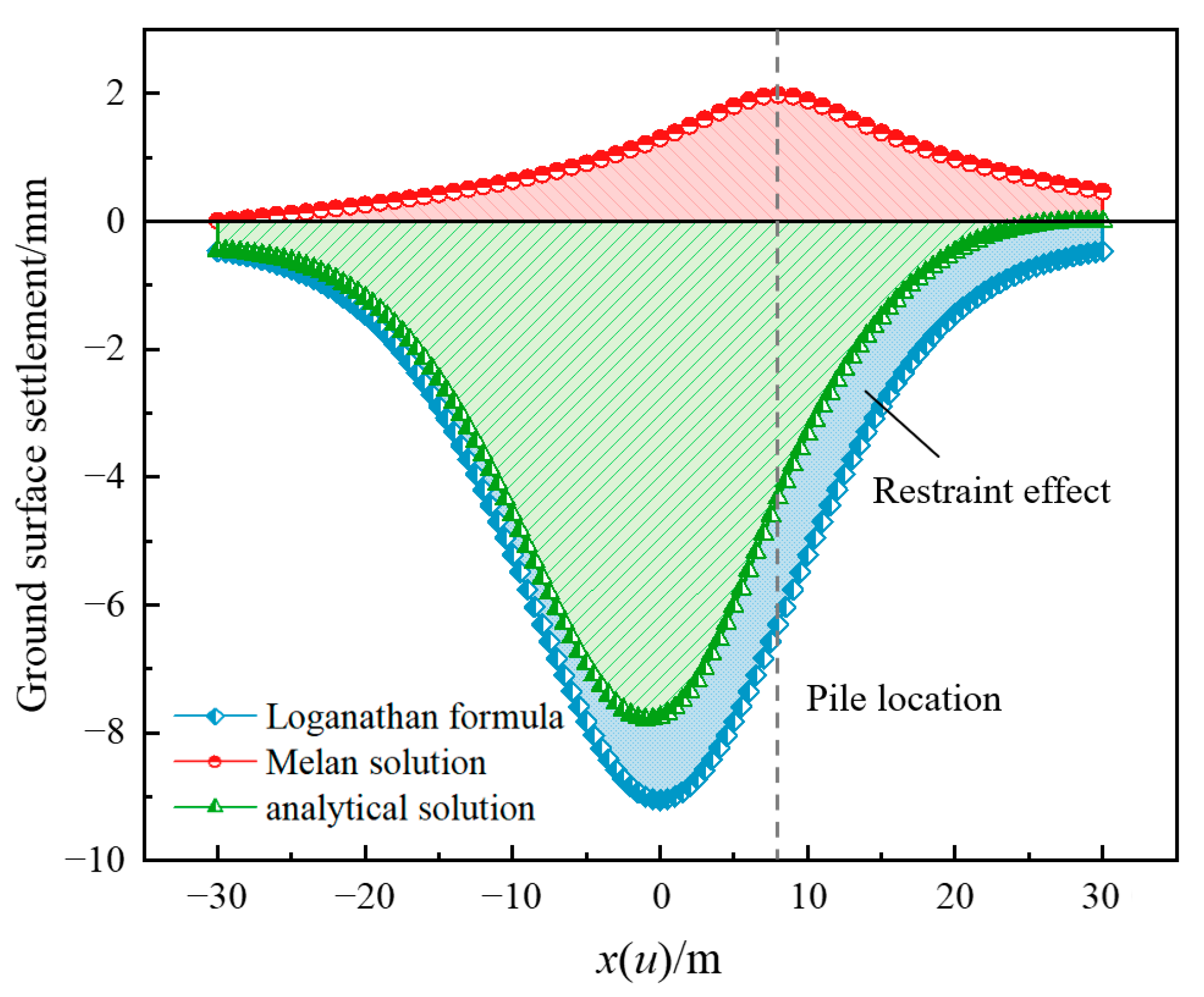
The restraint mechanism of isolation piles on the surface settlement trough induced by shield tunnelling is analyzed based on pile-soil-tunnel interaction mechanism. The friction between pile and surrounding soil is the principal reason of restraint effect. Based on the Melan solution and Loganathan formula, the analytical solution is derived. The analytical solution could reflect the restraint effect of isolation pile on the surface settlement trough from the internal mechanism;
(2)
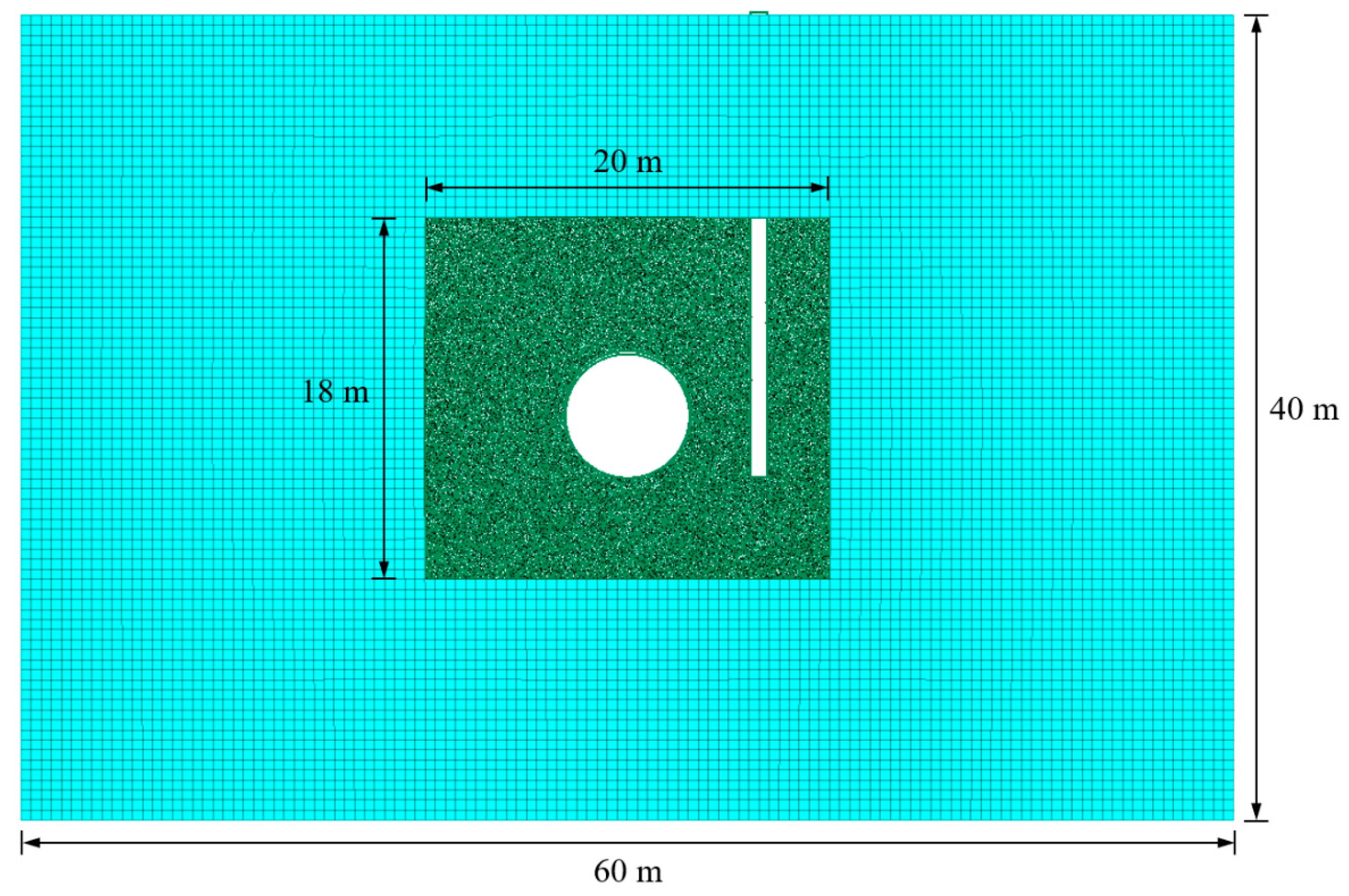
Taking the Changsha Metro Line 5 from East Laodong Road Station to Huaya Station, where shield tunnelling passes through Huaya International Hotel at a close distance as an engineering background. The FDM-DEM coupling technique is introduced to establish the numerical model. The coupling numerical model could simultaneously satisfy the engineering analysis scale and reflect the friction characteristics between isolation pile and soil particles;
(3)
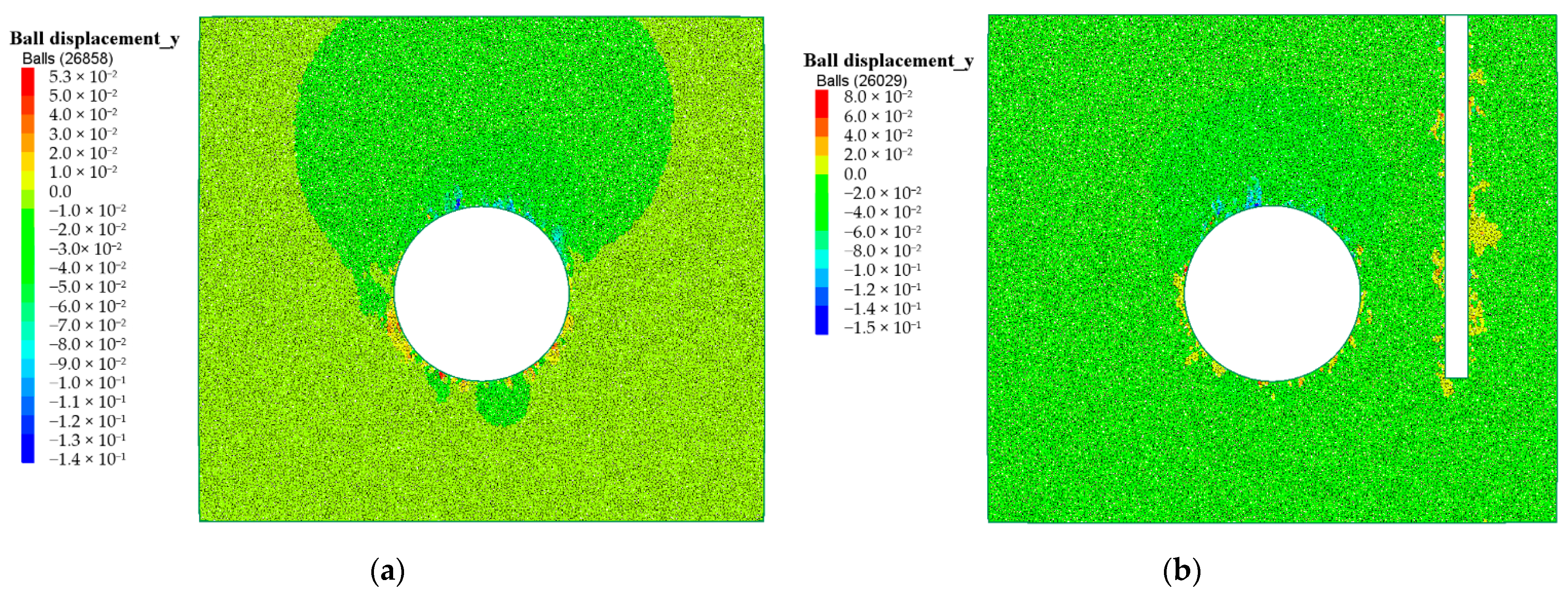
The FDM-DEM coupling model can simulate the impact of different ground loss rates on surface settlement trough by deleting and activating preset circle walls. The affected zone above the tunnel top has a wider range and a more uniform variation after shield tunnelling without isolation pile, while the range of affected zone decreases under the influence of isolation pile. The existence of isolation pile blocks the continuous development of soil displacement;
(4)
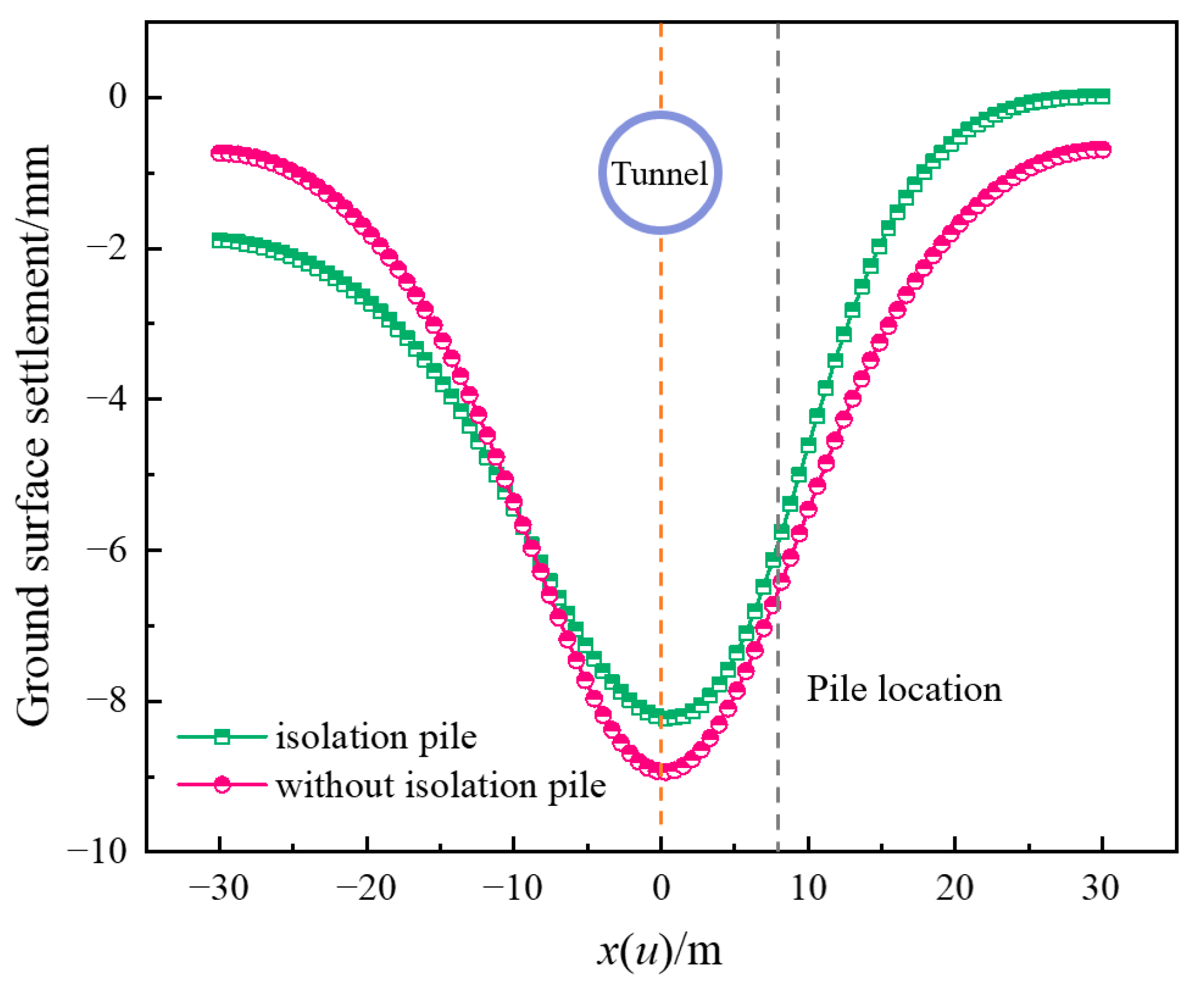
Comparing with field measured data, the applicability and reliability of the analytical solution and the FDM-DEM coupling model proposed in this study are verified. The ultimate surface settlement trough induced by shield tunnelling presents an asymmetric distribution due to the restraint effect of isolation pile on surrounding soil. The maximum surface settlement with isolation piles is less than that without isolation piles. Meanwhile, when isolation piles are pre-installed on one side of the tunnel, surface settlement tends to develop more on the side without isolation piles.

Author Contributions

Conceptualization, Y.S.; methodology, Y.S.; validation, K.H., Y.S. and X.K.; investigation, Y.S. and X.H.; resources, Y.S.; data curation, Y.S. and R.L.; writing—original draft preparation, Y.S.; writing—review and editing, K.H.; visualization, Y.S. and Q.W.; supervision, K.H.; funding acquisition, K.H. All authors have read and agreed to the published version of the manuscript.

Funding

This research was funded by the National Natural Science Foundation of China, grant number 52078060, the National Science Foundation of Hunan Province, grant number 2020JJ4606, the International Cooperation and Development Project of Double-First-Class Scientific Research in Changsha University of Science & Technology, grant number 2018IC19 and the Innovative Program of Key Disciplines with Advantages and Characteristics of Civil Engineering of Changsha University of Science & Technology, grant number 18ZDXK05.

Institutional Review Board Statement

Not applicable.

Informed Consent Statement

Not applicable.

Data Availability Statement

Some or all data and models from the study are available from the corresponding author by request.

Conflicts of Interest

The authors declare no conflict of interest.

References

  1. Huang, K.; Sun, Y.W.; Zhou, D.Q.; Li, Y.J.; Jiang, M.; Huang, X.Q. Influence of water-rich tunnel by shield tunneling on existing bridge pile foundation in layered soils. J. Cent. South Univ. 2021, 28, 2574–2588. [Google Scholar] [CrossRef]
  2. Ding, W.Q.; Gong, C.J.; Mosalam, K.M.; Soga, K. Development and application of the integrated sealant test apparatus for sealing gaskets in tunnel segmental joints. Tunn. Undergr. Space Technol. 2017, 63, 54–68. [Google Scholar] [CrossRef]
  3. Gong, C.J.; Ding, W.Q.; Mosalam, K.M.; Günay, S.; Soga, K. Comparison of the structural behavior of reinforced concrete and steel fiber reinforced concrete tunnel segmental joints. Tunn. Undergr. Space Technol. 2017, 68, 38–57. [Google Scholar] [CrossRef]
  4. Lei, M.F.; Zhu, B.B.; Gong, C.J.; Ding, W.Q.; Liu, L.H. Sealing performance of a precast tunnel gasketed joint under high hydrostatic pressures: Site investigation and detailed numerical modeling. Tunn. Undergr. Space Technol. 2021, 115, 104082. [Google Scholar] [CrossRef]
  5. Zhou, Z.; Zhang, J.J.; Gong, C.J. Automatic detection method of tunnel lining multi-defects via an enhanced You Only Look Once network. Comput. Aided Civ. Infrastruct. Eng. 2022, 37, 762–780. [Google Scholar] [CrossRef]
  6. Huang, K.; Sun, Y.W.; Yang, J.S.; Li, Y.J.; Jiang, M.; Huang, X.Q. Three-dimensional displacement characteristics of adjacent pile induced by shield tunneling under the influence of multiple factors. J. Cent. South Univ. 2022, 29. [Google Scholar] [CrossRef]
  7. Bai, Y.; Yang, Z.H.; Jiang, Z.W. Key protection techniques adopted and analysis of influence on adjacent buildings due to the Bund Tunnel construction. Tunn. Undergr. Space Technol. 2014, 41, 24–34. [Google Scholar] [CrossRef]
  8. Fu, J.Y.; Yang, J.S.; Zhu, S.T.; Shi, Y.F. Performance of jet-grouted partition walls in mitigating the effects of shield-tunnel construction on adjacent piled structures. J. Perform. Constr. Facil. 2017, 31, 04016096. [Google Scholar] [CrossRef]
  9. Huang, K.; Sun, Y.W.; He, J.; Huang, X.Q.; Jiang, M.; Li, Y.J. Comparative study on grouting protection schemes for shield tunneling to adjacent viaduct piles. Adv. Mater. Sci. Eng. 2021, 2021, 5546970. [Google Scholar] [CrossRef]
  10. Peck, R.B. Deep excavations and tunneling in soft ground. In Proceedings of the 7th International Conference on Soil Mechanics and Foundation Engineering, Mexico City, Mexico, 29 August 1969. [Google Scholar]
  11. Fantera, L.; Rampello, S.; Masini, L. A mitigation technique to reduce ground settlements induced by tunnelling using diaphragm walls. Procedia Eng. 2016, 158, 254–259. [Google Scholar] [CrossRef] [Green Version]
  12. Ding, Z.; Wei, X.J.; Wei, G. Prediction methods on tunnel-excavation induced surface settlement around adjacent building. Geomech. Eng. 2017, 12, 185–195. [Google Scholar] [CrossRef]
  13. Huang, K.; Sun, Y.W.; Huang, X.Q.; Li, Y.J.; Jiang, M.; Liu, R.N. Effects of different construction sequences on ground surface settlement and displacement of single long pile due to twin paralleled shield tunneling. Adv. Civ. Eng. 2021, 2021, 5559233. [Google Scholar] [CrossRef]
  14. Rampello, S.; Fantera, L.; Masini, L. Efficiency of embedded barriers to mitigate tunnelling effects. Tunn. Undergr. Space Technol. 2019, 89, 109–124. [Google Scholar] [CrossRef]
  15. Masini, L.; Rampello, S. Predicted and observed behaviour of pre-installed barriers for the mitigation of tunnelling effects. Tunn. Undergr. Space Technol. 2021, 118, 104200. [Google Scholar] [CrossRef]
  16. Franza, A.; Losacco, N.; Ledesma, A.; Viggiani, G.M.B.; Jimenez, R. Protecting surface and buried structures from tunnelling using pile walls: A prediction model. Can. Geotech. J. 2021, 58, 1590–1602. [Google Scholar] [CrossRef]
  17. Sun, Y.W.; Huang, K.; Li, Y.J. Influence of existing bridge pile foundation on the deformation of surface settlement trough induced by shield tunneling. J. Transp. Sci. Eng. 2022, 38, 79–87. (In Chinese). [Google Scholar]
  18. Cao, L.Q.; Chen, X.S.; Shen, X.; Zhang, D.L.; Su, D.; Fang, H.C. Theoretical analysis of the barrier effect of embedded isolation piles on tunneling-induced vertical ground displacements. Comput. Geotech. 2022, 144, 104609. [Google Scholar] [CrossRef]
  19. Loganathan, N.; Poulos, H.G. Analytical prediction for tunneling-induced ground movements in clays. J. Geotech. Geoenviron. Eng. 1998, 124, 846–856. [Google Scholar] [CrossRef]
  20. Melan, E. Der Spannungszustand der durch eine Einzelkraft im Innern beanspruchten Halbscheibe. J. Appl. Math. Mech. 1932, 12, 343–346. (In German). [Google Scholar] [CrossRef]
  21. Poulos, H.G.; Davis, E.H. Elastic Solutions for Soil and Rock Mechanics, 1st ed.; John Wiley and Sons: Hoboken, NJ, USA, 1974; pp. 1–28. [Google Scholar]
  22. Verruijt, A.; Booker, J.R. Complex variable analysis of Mindlin’s tunnel problem. In Proceedings of the Developments in Theoretical Geomechanics, Sydney, Australia, 16–17 November 2000. [Google Scholar]
  23. Cai, M.; Kaiser, P.K.; Morioka, H.; Minami, M.; Maejima, M.; Tasaka, Y.; Kurose, H. FLAC/PFC coupled numerical simulation of AE in large-scale underground excavations. Int. J. Rock Mech. Min. Sci. 2007, 44, 550–564. [Google Scholar] [CrossRef]
  24. Trivino, L.F.; Mohanty, B. Assessment of crack initiation and propagation in rock from explosion-induced stress waves and gas expansion by cross-hole seismometry and FEM–DEM method. Int. J. Rock Mech. Min. Sci. 2015, 77, 287–299. [Google Scholar] [CrossRef]
  25. Qu, T.M.; Wang, S.Y.; Fu, J.Y.; Hu, Q.X. Numerical examination of EPB shield tunneling-induced responses at various discharge ratios. J. Perform. Constr. Facil. 2019, 33, 04019035. [Google Scholar] [CrossRef]
  26. Yin, Z.Y.; Wang, P.; Zhang, F.S. Effect of particle shape on the progressive failure of shield tunnel face in granular soils by coupled FDM-DEM method. Tunn. Undergr. Space Technol. 2020, 100, 103394. [Google Scholar] [CrossRef]
Figure 1. Pile-soil-tunnel interaction mechanism.
Applsci 12 04845 g001
Figure 2. Calculation diagram of Melan solution: (a) Melan solution and (b) this study.
Applsci 12 04845 g002
Figure 3. Relationship among building, isolation pile, and tunnel: (a) top view and (b) sectional view.
Applsci 12 04845 g003
Figure 4. Coupling Mechanism Based on FLAC2D and PFC2D.
Applsci 12 04845 g004
Figure 5. FDM-DEM Coupling Numerical Model.
Applsci 12 04845 g005
Figure 6. Results of analytical solution.
Applsci 12 04845 g006
Figure 7. Contours of soil displacement: (a) without isolation pile and (b) with isolation pile.
Applsci 12 04845 g007
Figure 8. Results of FDM-DEM Coupling.
Applsci 12 04845 g008
Figure 9. Comparison with field measured data.
Applsci 12 04845 g009
Table 1. Macroscopic and microscopic physical and mechanical parameters of soil.
Macroscopic ParametersYoung’s Modulus (MPa)Density (kg/m3)Poisson’s RatioFriction Angle (°)Cohesion (kPa)
Soil mass7522500.253040
Microscopic ParametersEffective Modulus (MPa)Normal Stiffness (N∙m−1)Tangential Stiffness (N∙m−1)Normal Bond (kPa)Shear Bond (kPa)
Soil mass18.57.5 × 1064.5 × 1064045
Publisher’s Note: MDPI stays neutral with regard to jurisdictional claims in published maps and institutional affiliations.

