
Effect of Jack Thrust Angle Change on Mechanical Characteristics of Shield Tunnel Segmental Linings Considering Additional Constrained Boundaries


Abstract
:1. Introduction
2. Project Overview
3. Numerical Modelling
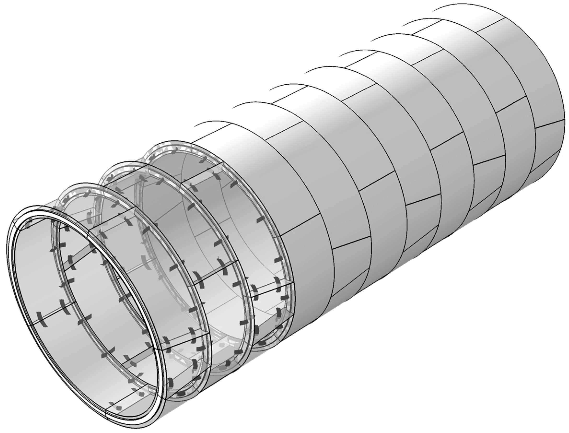
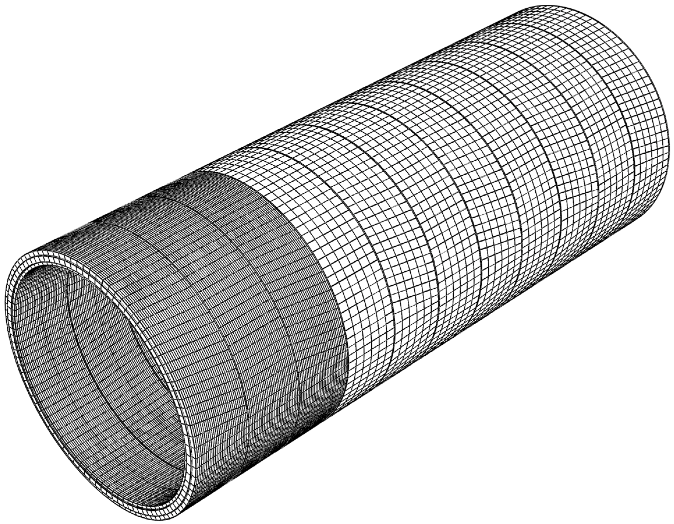
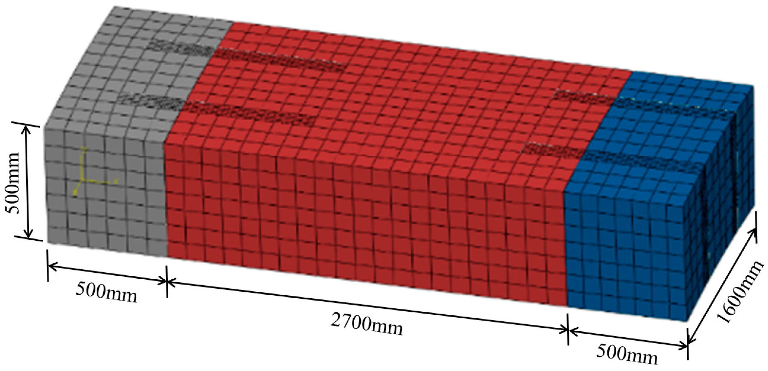
3.1. D Finite Element Model
3.2. Material Properties
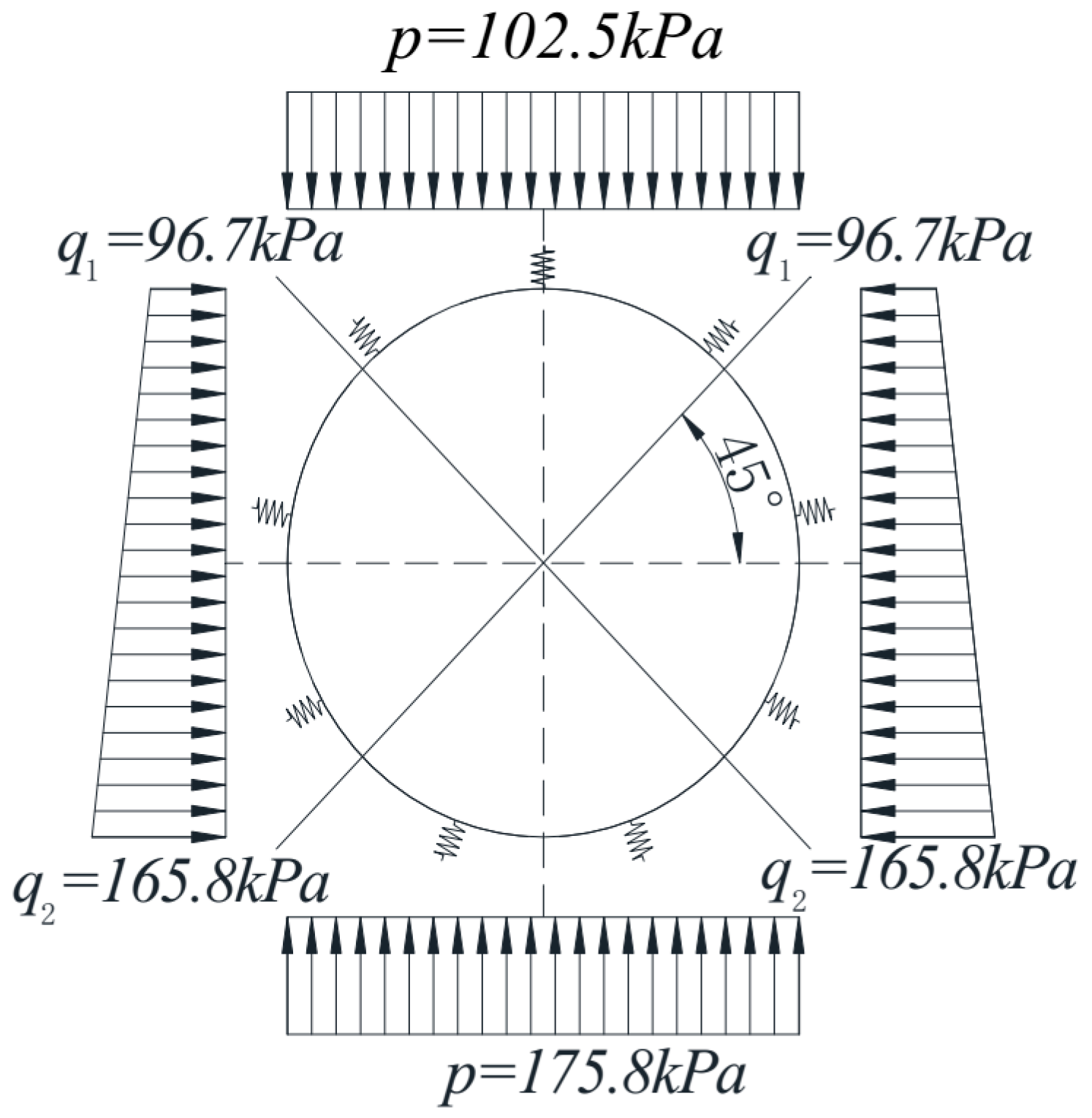
3.3. Water and Soil Pressure
3.4. Grouting Pressure
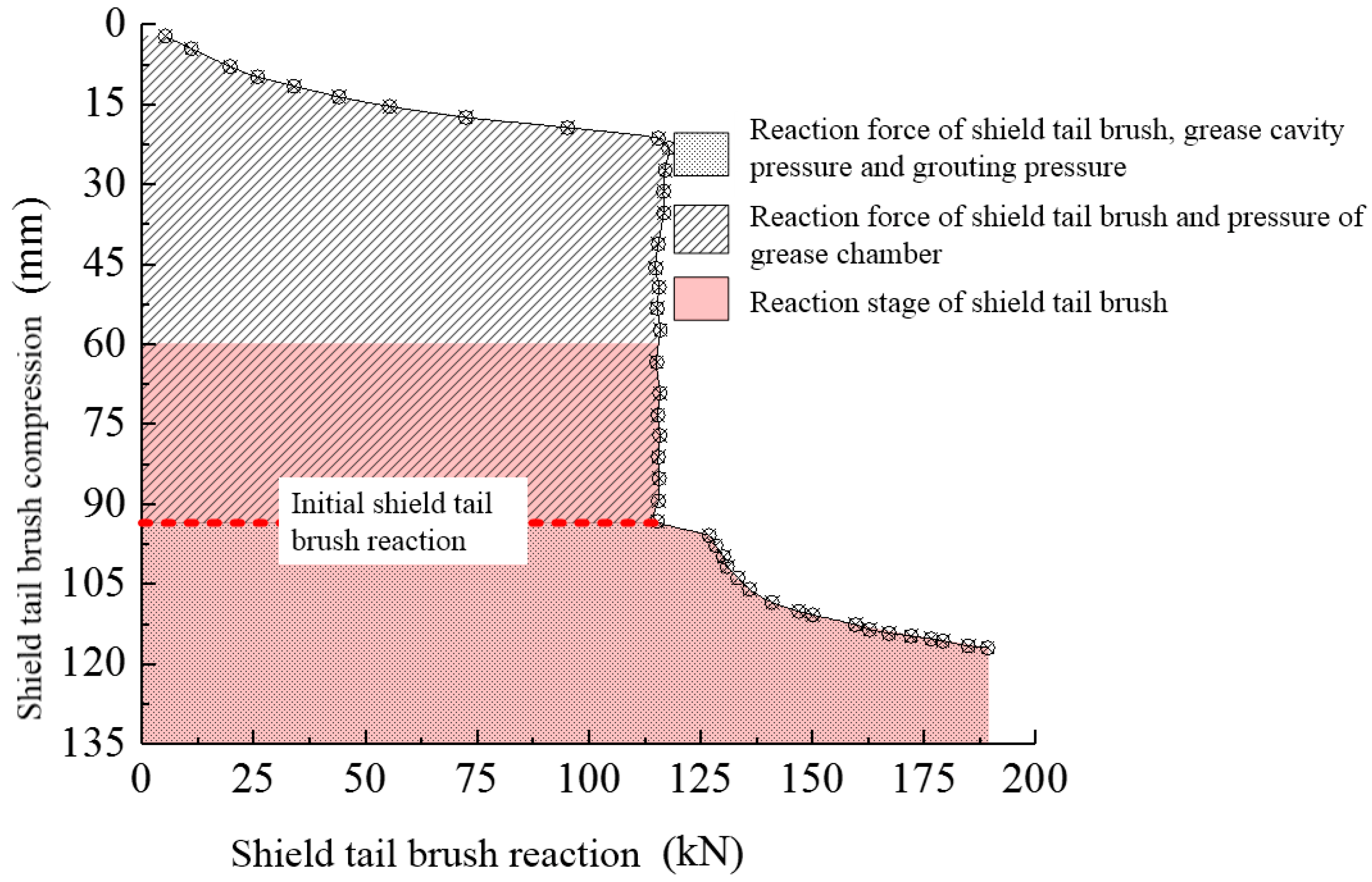
3.5. Tail Reaction
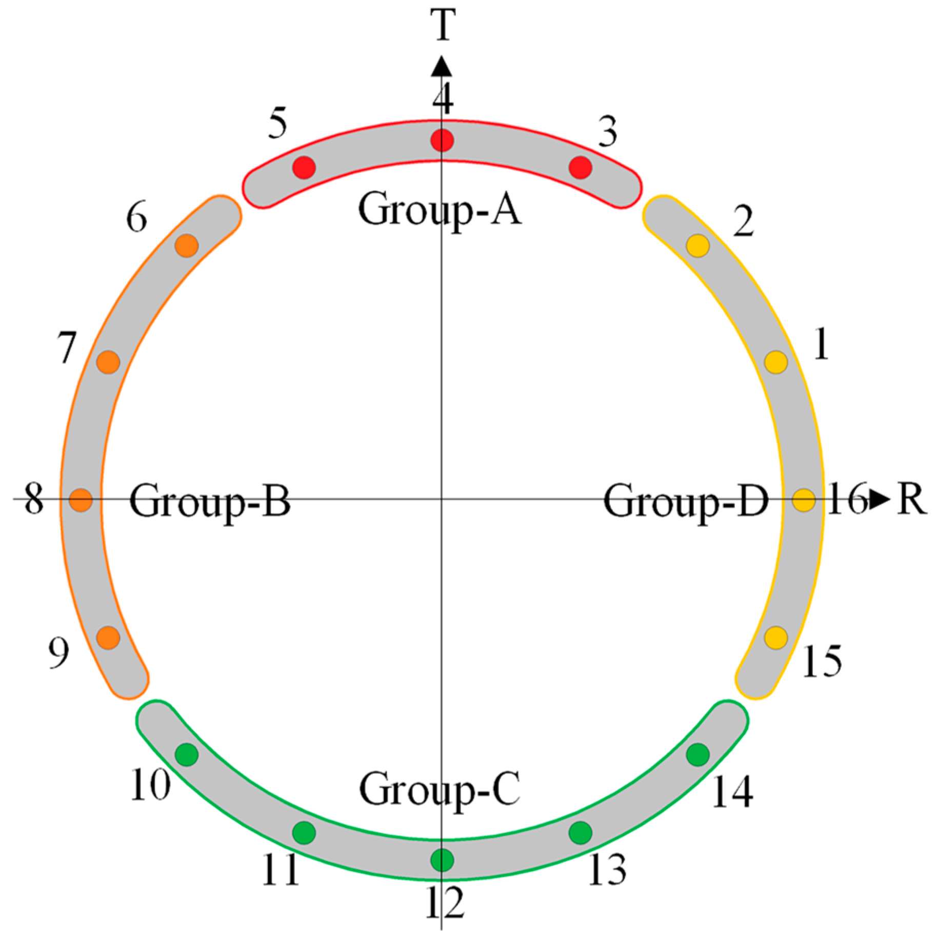
3.6. Jack Thrust
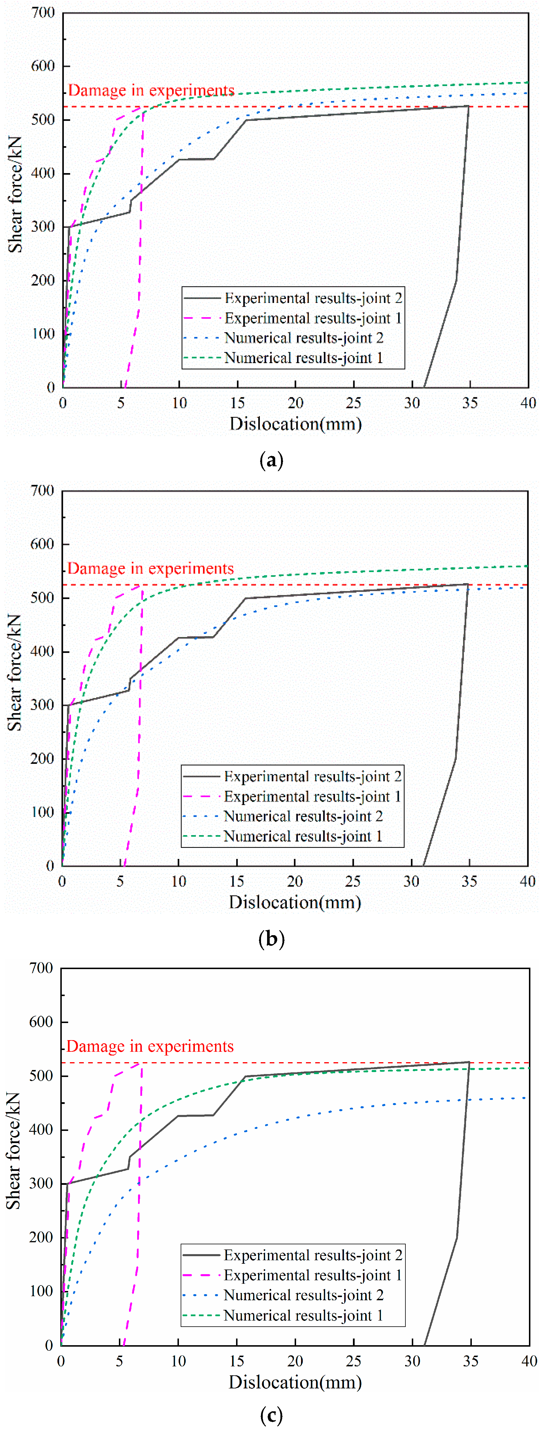
3.7. Verification
4. Analysis of Calculation Results
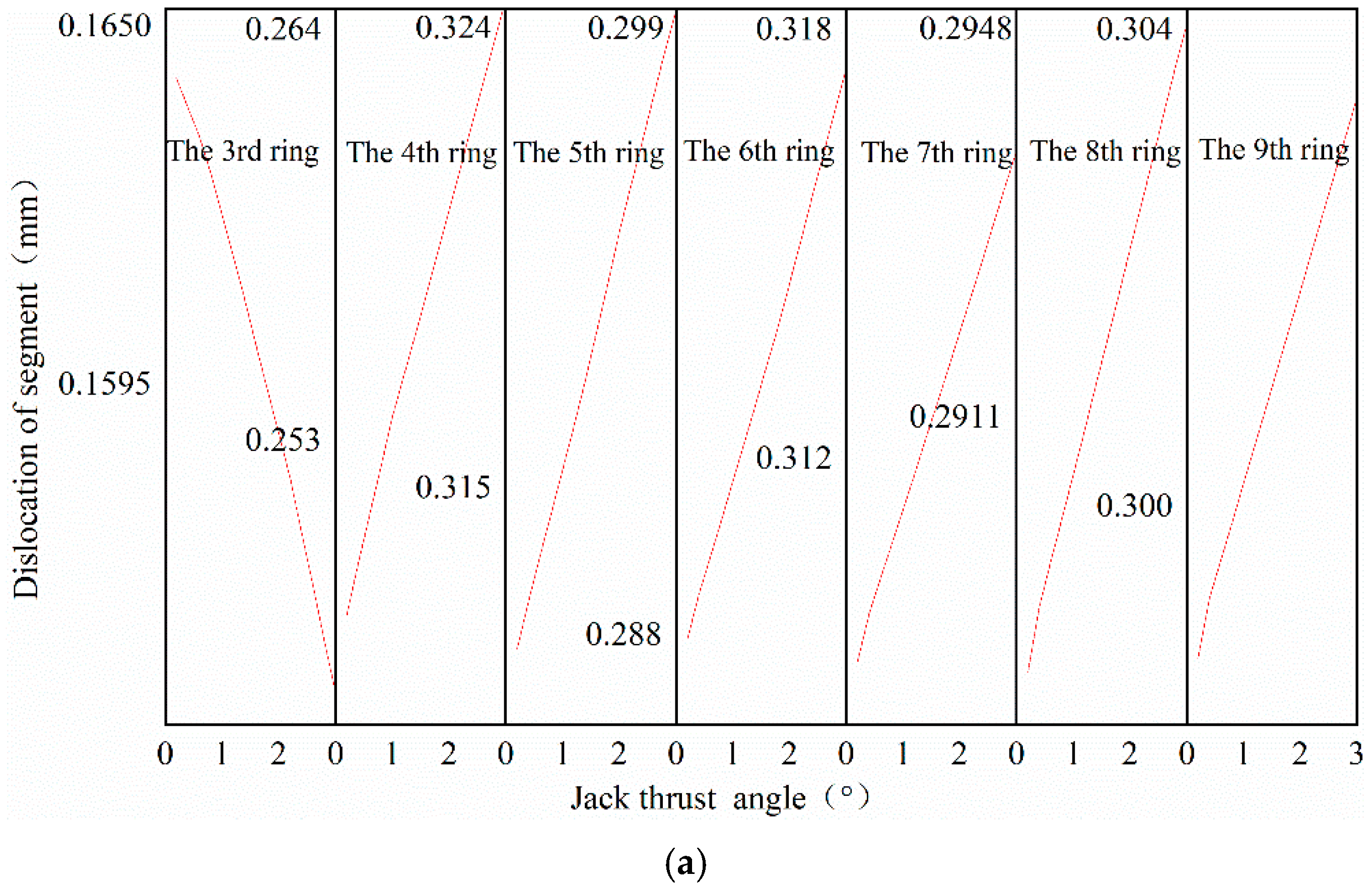
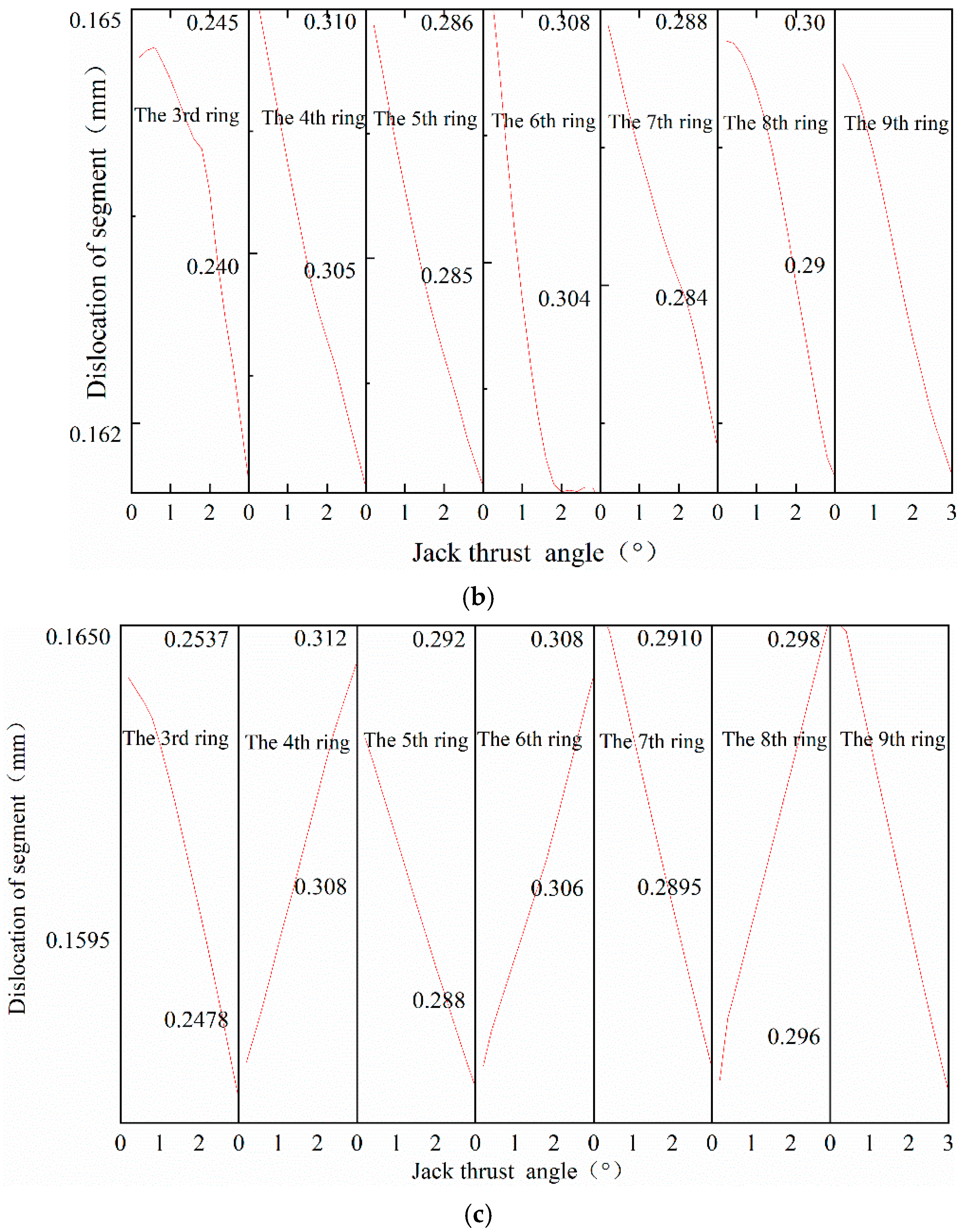
4.1. Segment Staggering
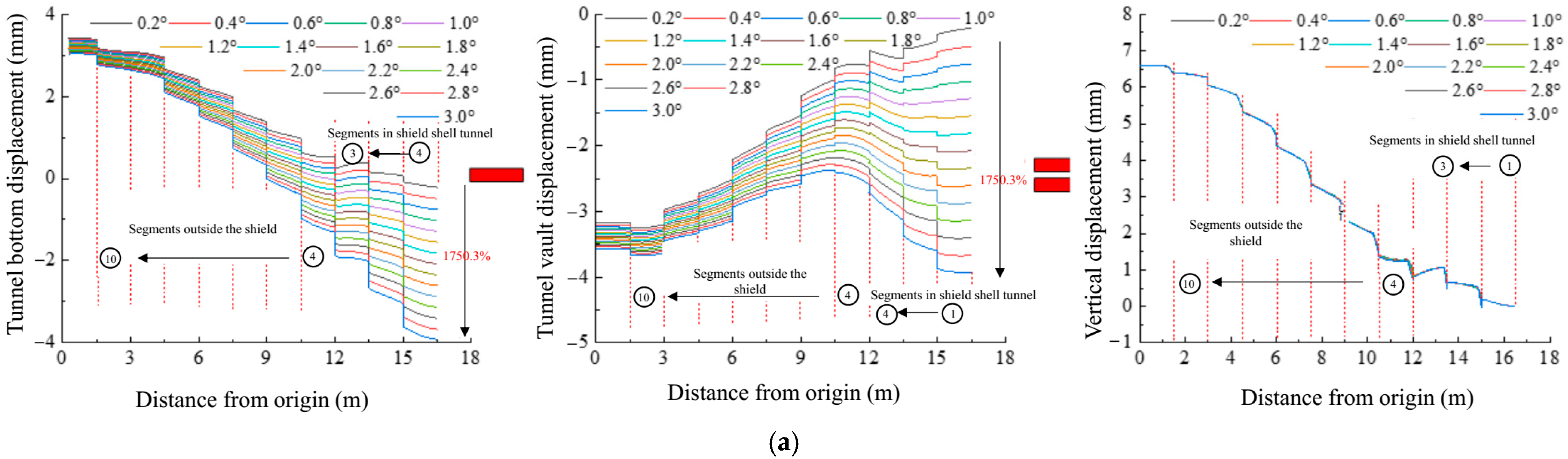
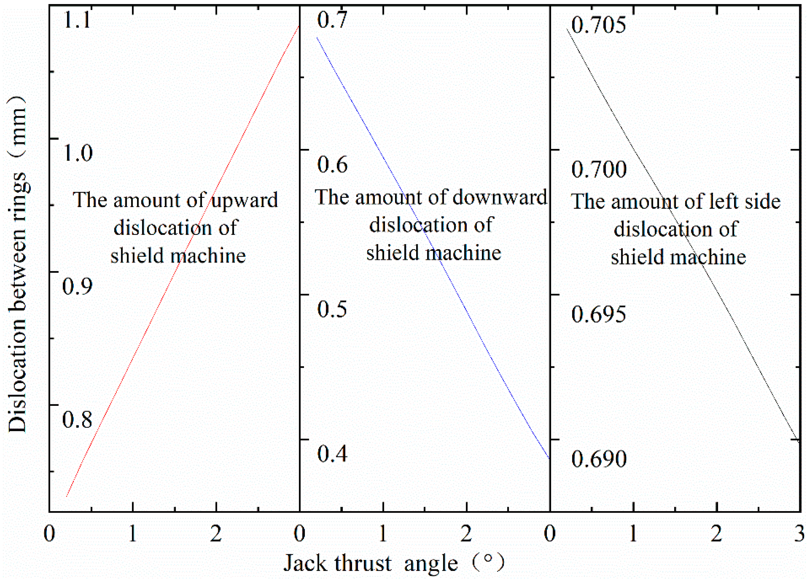
4.2. Displacement and Dislocation between Rings
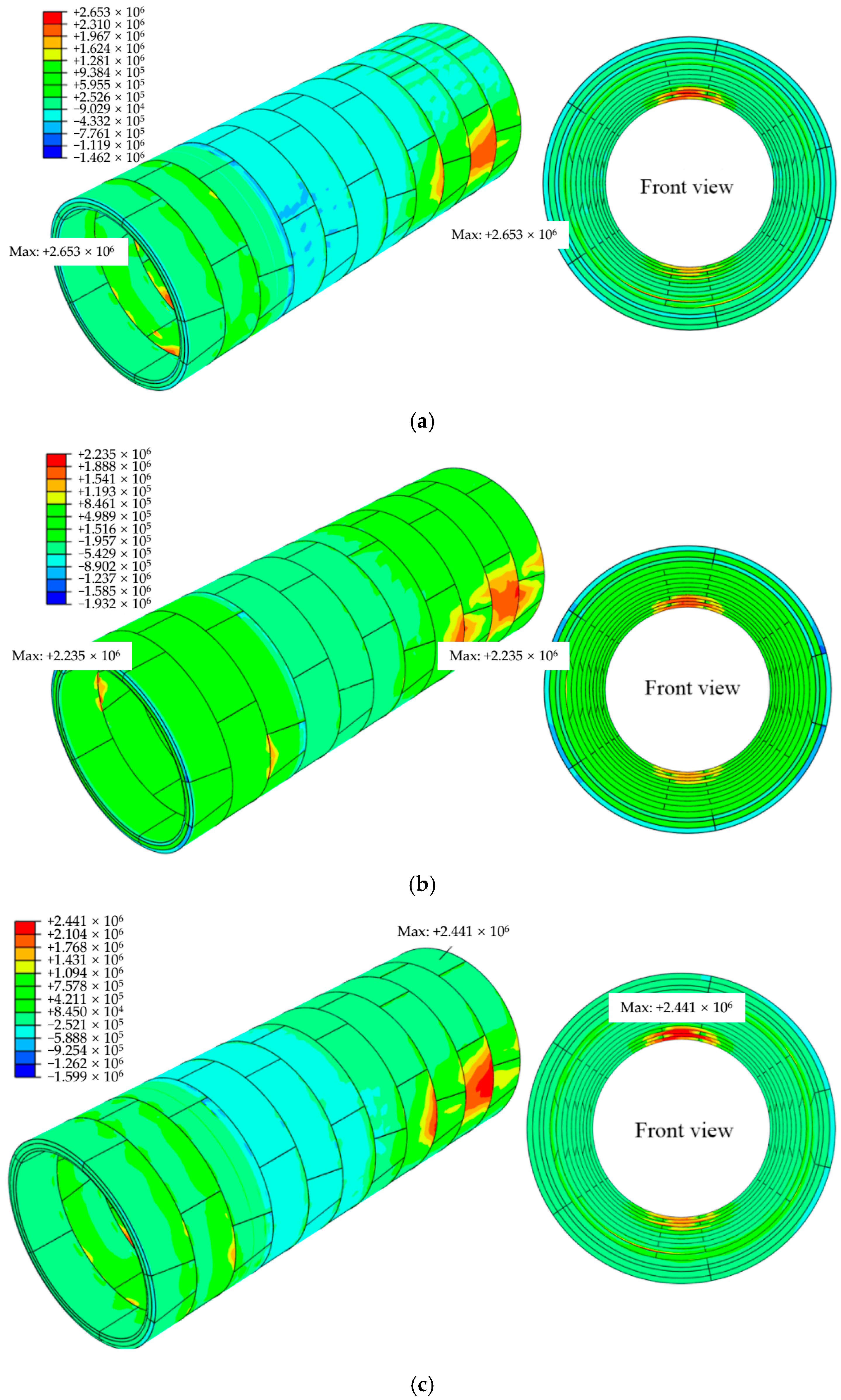
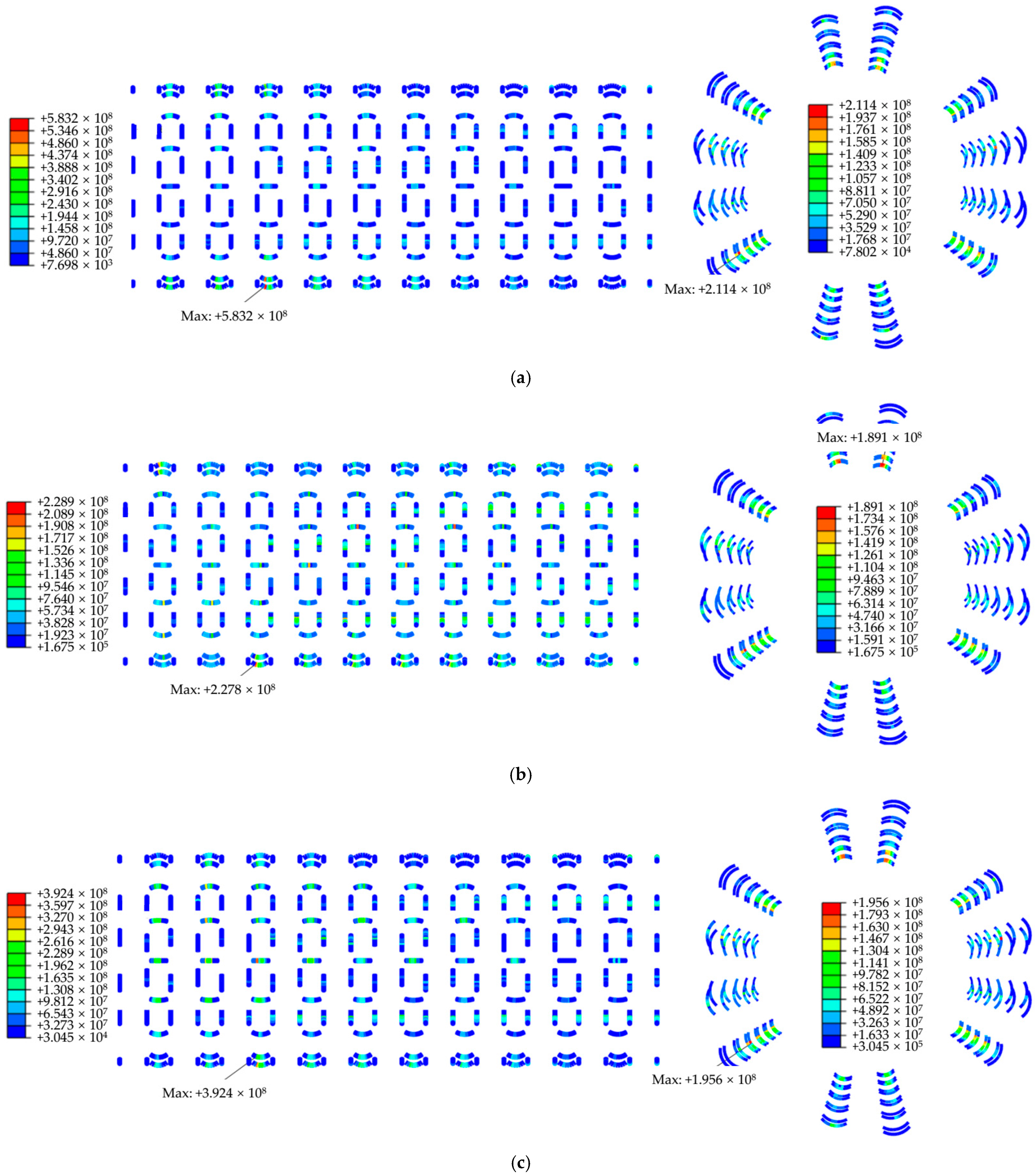
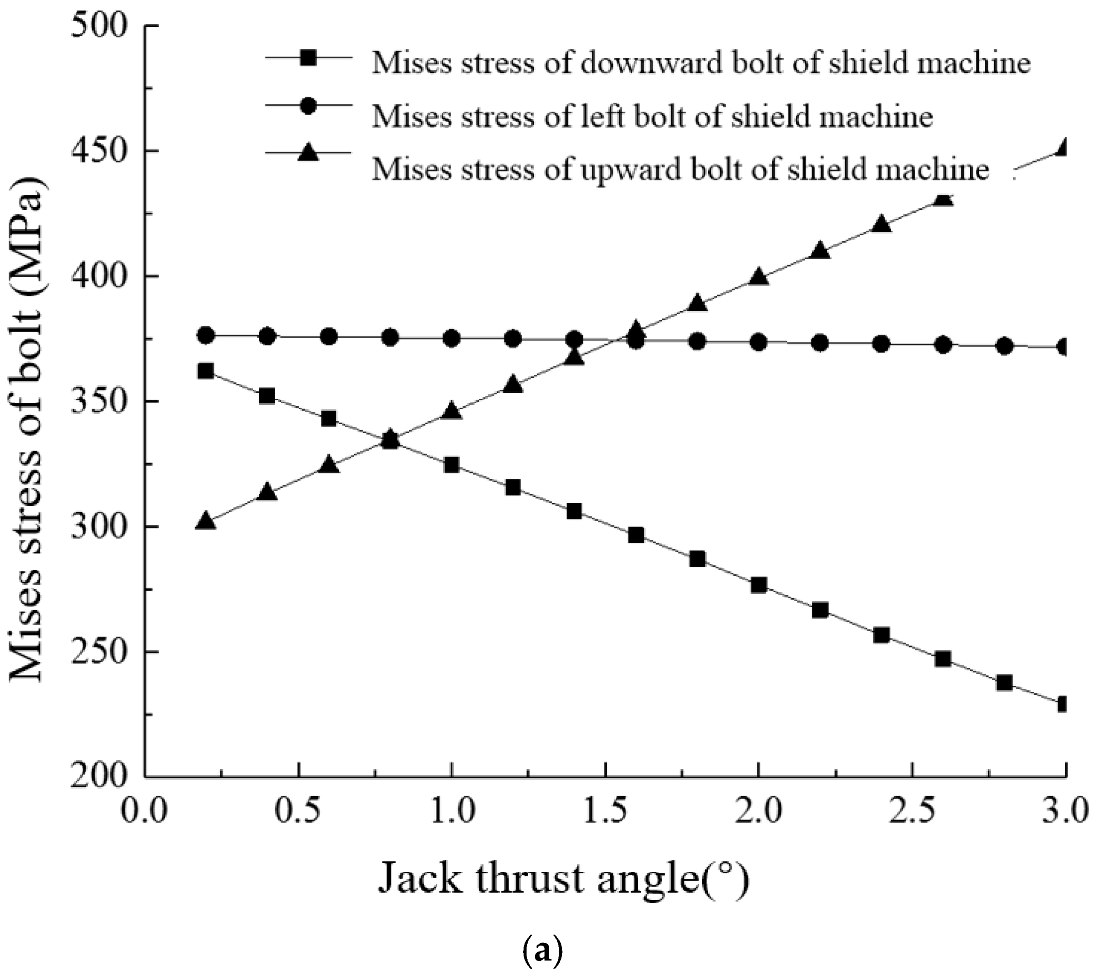
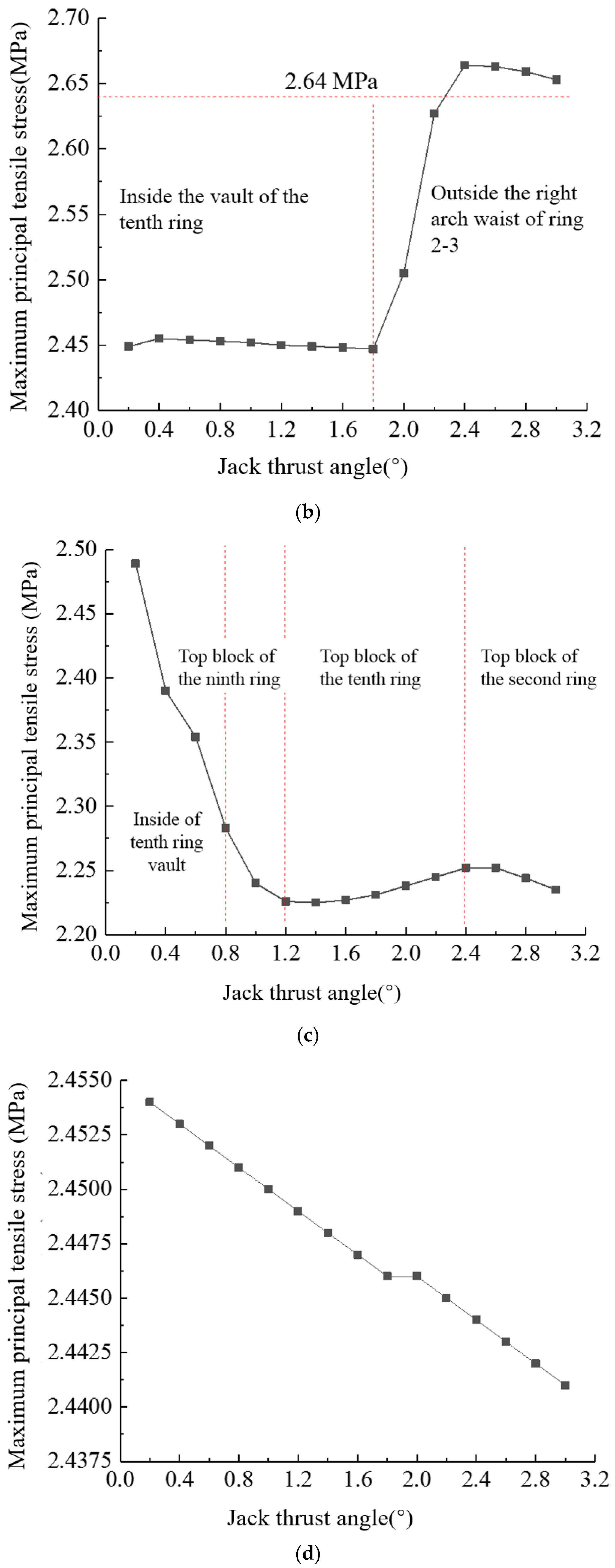
4.3. Stress of Segment and Bolt
5. Conclusions
- (1)
- No matter how the shield machine attitude is adjusted, the maximum amount of segment staggering occurs at the lower side of the arch waist, and the second ring segment out of the shield tail has the most substantial amount.
- (2)
- When the shield machine goes up, down, and left, the maximum amount of staggering between rings occurs at the joint position of the 3rd–4th ring at the bottom of the arch. When the shield machine goes up, the joint between the rings increases linearly by 0.127 mm/° with the increase of the jack thrust deflection angle.
- (3)
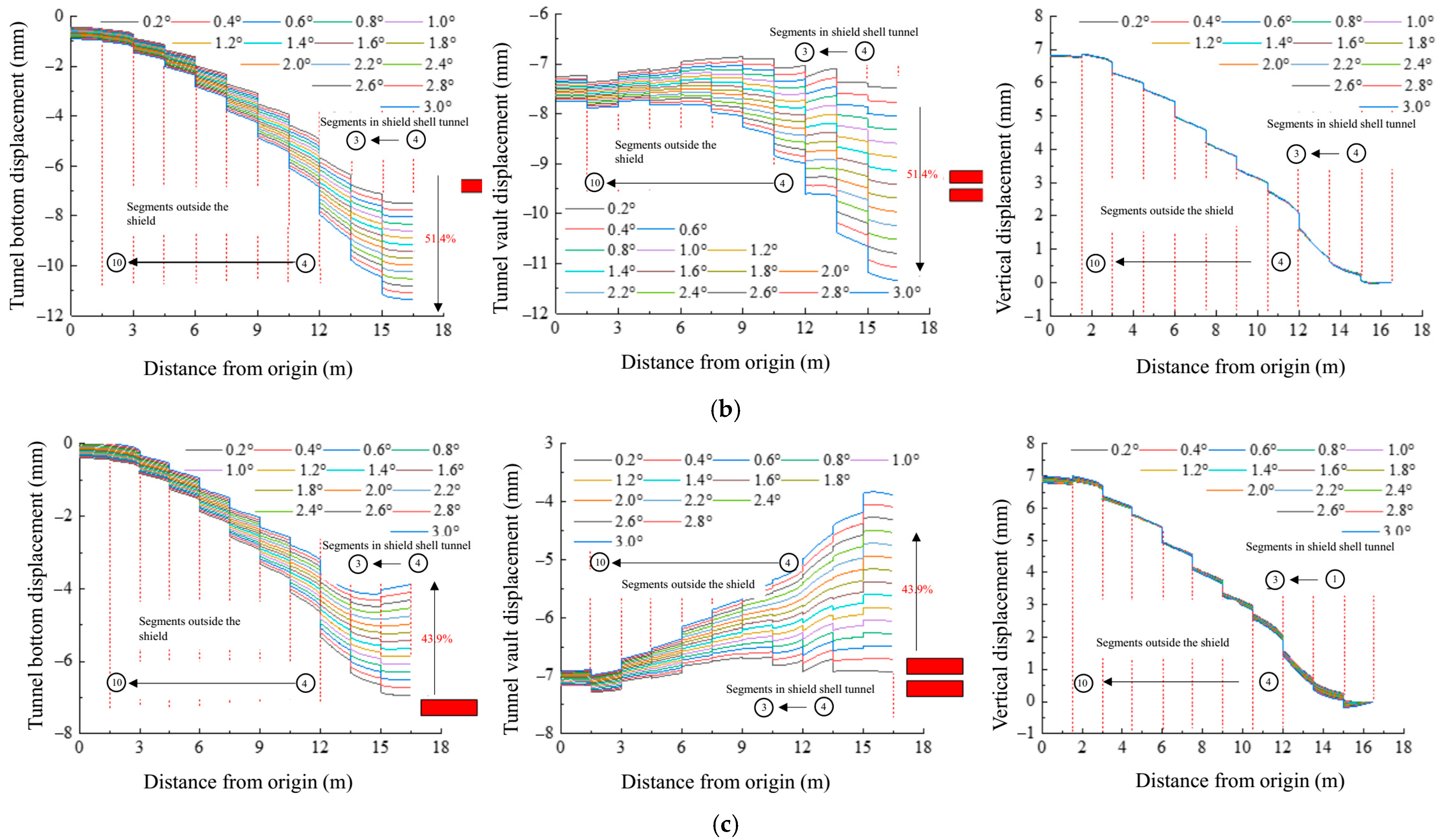
- The development direction of tunnel displacement is opposite to that of jack’s thrust angle, and the lateral deformation of the tunnel is not affected by the posture adjustment of the shield machine.
- (4)
- When the shield machine goes down, the structural stress tends to be reasonable. When the shield machine goes up, the structure has been damaged, which is an unfavorable combination of tunnel load, and the deflection angle should be controlled within 2.2°. When the shield machine goes left, it only affects the variation of deformation and stress with the deviation angle of jack thrust force.
Author Contributions
Funding
Acknowledgments
Conflicts of Interest
References
- Shi, C.H.; Wang, Z.X.; Gong, C.J.; Liu, J.W.; Peng, Z.; Cao, C.Y. Prediction of the additional structural response of segmental tunnel linings induced by asymmetric jack thrusts. Tunn. Undergr. Space Technol. 2022, 124, 104471. [Google Scholar] [CrossRef]
- Shen, X.; Yuan, D.J.; Jin, D.L. Influence of shield attitude change on shield–soil interaction. Appl. Sci. 2019, 9, 1812. [Google Scholar] [CrossRef] [Green Version]
- Lorenzo, S.G. Design guidelines for concrete segmental linings in transverse interaction with the TBM. Tunn. Undergr. Space Technol. 2022, 122, 104388. [Google Scholar] [CrossRef]
- Lee, H.S.; Na, Y.M.; Jang, H.S.; Suk, I.H.; Kang, S.H.; Kim, H.T.; Park, J.K. A Study on the Stability of Shield TBM Thrust Jack in the Behavior of Operating Fluid According to Thrust Force. J. Korean Soc. Manuf. Process. Eng. 2019, 18, 38–45. [Google Scholar] [CrossRef]
- Qiao, S.; Xu, P.; Liu, R.; Wang, G. Study on the Horizontal Axis Deviation of a Small Radius TBM Tunnel Based on Winkler Foundation Model. Appl. Sci. 2020, 10, 784. [Google Scholar] [CrossRef] [Green Version]
- Zhou, J.H.; Wu, D.; Zhou, S.H.; Cui, Y.X. Analysis on damage cause of shield tunnel segments during construction. Adv. Mat. Res. 2012, 594, 1308–1313. [Google Scholar] [CrossRef]
- Medeghini, F.; Trabucchi, I.; Conforti, A.; Tiberti, G.; Plizzari, G.A. Local splitting and crushing behavior under TBM hydraulic jacks. Galle. Grand. Opere. Sotte. 2018, 127, 37–44. [Google Scholar]
- Conforti, A.; Tiberti, G.; Plizzari, G.A. Splitting and crushing failure in FRC elements subjected to a high concentrated load. Compos. Part B Eng. 2016, 105, 82–92. [Google Scholar] [CrossRef]
- Zhe, G.; Li, S.C.; Zhao, S.S.; Zhang, J.Y. Nonlinear dynamic analysis and application of thrust force for slurry balance shield. Rock Soil Mech. 2018, 39, 469–476. [Google Scholar]
- Peng, Z.Y.; Liu, W.N.; Ding, D.Y.; Yang, X.R.; Yan, M.; Lu, W.D. Arrangement of thrust force about partitioned key segment. J. Cent. Sou. Univ. Sci. Technol. 2014, 45, 4018–4025. [Google Scholar]
- Jamshidi Avanaki, M. Effects of hybrid steel fiber reinforced composites on structural performance of segmental linings subjected to TBM jacks. Struct. Concr. 2019, 20, 1909–1925. [Google Scholar] [CrossRef]
- Yao, Y.; Bakhshi, M.; Nasri, V.; Mobasher, B. Interaction diagrams for design of hybrid fiber-reinforced tunnel segments. Mater. Struct. 2018, 51, 35. [Google Scholar] [CrossRef]
- Neu, G.E.; Edler, P.; Freitag, S.; Gudžulić, V.; Meschke, G. Reliability based optimization of steel-fibre segmental tunnel linings subjected to thrust jack loadings. Eng. Struct. 2022, 254, 113752. [Google Scholar] [CrossRef]
- Zhou, Q.; Chen, J.; He, Z.; Zhang, H. Design of intellectualized controller of shield machine. J. Tongji Univ. Nat. Sci. 2008, 36, 76–80. [Google Scholar]
- Cho, S.H.; Kim, J.; Won, J.; Kim, M.K. Effects of jack force and construction steps on the change of lining stresses in a TBM tunnel. KSCE J. Civ. Eng. 2017, 21, 1135–1146. [Google Scholar] [CrossRef]
- Chaipanna, P.; Jongpradist, P. 3D-FEM analysis of shield tunnel construction with ground-spring model. Geomate J. 2017, 12, 58–62. [Google Scholar] [CrossRef]
- Deng, K.S.; Li, Y.Y.; Yin, Z.R. Thrust distribution characteristics of thrust systems of shield machines based on spatial force ellipse model in mixed ground. J. Mech. Sci. Technol. 2016, 30, 279–286. [Google Scholar] [CrossRef]
- Chaipanna, P.; Jongpradist, P. 3D response analysis of a shield tunnel segmental lining during construction and a parametric study using the ground-spring model. Tunn. Undergr. Space Technol. 2019, 90, 369–382. [Google Scholar] [CrossRef]
- Dastjerdy, B.; Hasanpour, R.; Samimi Namin, F.; Chakeri, H. 3D computational study of tunnel segment behaviour under loading by TBM thrust jacks. Geomech. Geoengin. 2021, 16, 182–197. [Google Scholar] [CrossRef]
- Jamshidi, A.M.; Abedi, M.; Hoseini, A. Experimental and numerical-based design of hybrid steel fibre-reinforced concrete tunnels. Mag. Concr. Res. 2020, 72, 720–733. [Google Scholar] [CrossRef]
- Trabucchi, I.; Tiberti, G.; Plizzari, G.A. A parametric numerical study on the behavior of large precast tunnel segments during TBM thrust phase. Eng. Struct. 2021, 241, 112253. [Google Scholar] [CrossRef]
- He, Y.; Yang, Z.H.; Liu, X.; Ding, W.Q. Theoretical solution for failure mechanism of circumferential joint of shield tunnel segment connected using diagonal bolts. Tunn. Constr. 2021, 41, 933. [Google Scholar] [CrossRef]


| Uniaxial Compressive Stress/(MPa) | Uniaxial Inelastic Compressive Strain | Damage Parameter | Uniaxial Tensile Stress/(MPa) | Tensile Strain Due to Uniaxial Cracking | Tensile Damage Factor |
|---|---|---|---|---|---|
| 5.769 | 0 | 0 | 2.640 | 0 | 0 |
| 21.107 | 5.96 × 10⁻⁵ | 0.037 | 2.168 | 7.93 × 10⁻⁵ | 0.275 |
| 30.056 | 3.03 × 10⁻⁴ | 0.122 | 1.677 | 1.26 × 10⁻⁴ | 0.438 |
| 32.454 | 7.37 × 10⁻⁴ | 0.239 | 1.344 | 1.69 × 10⁻⁴ | 0.565 |
| 27.726 | 1.54 × 10⁻³ | 0.435 | 1.120 | 2.08 × 10⁻⁴ | 0.658 |
| 21.198 | 2.40 × 10⁻³ | 0.610 | 0.962 | 2.45 × 10⁻⁴ | 0.725 |
| 16.413 | 3.21 × 10⁻³ | 0.730 | 0.845 | 2.82 × 10⁻⁴ | 0.775 |
| 13.142 | 3.97 × 10⁻³ | 0.807 | 0.756 | 3.17 × 10⁻⁴ | 0.813 |
| 10.858 | 4.71 × 10⁻³ | 0.857 | 0.685 | 3.52 × 10⁻⁴ | 0.842 |
| 9.205 | 5.43 × 10⁻³ | 0.891 | 0.628 | 3.86 × 10⁻⁴ | 0.864 |
| 7.966 | 6.13 × 10⁻³ | 0.914 | 0.581 | 4.21 × 10⁻⁴ | 0.882 |
| 7.009 | 6.82 × 10⁻³ | 0.931 | 0.541 | 4.54 × 10⁻⁴ | 0.897 |
| 5.636 | 8.20 × 10⁻³ | 0.953 | 0.508 | 4.88 × 10⁻⁴ | 0.909 |
| Soil Layer Number | The Thickness of the Soil Layer/m | Saturation Gravity/(kN/m3) | Coefficient of Subgrade Bed/(MPa/m) |
|---|---|---|---|
| plain fill soil ① 2 | 1 | 16 | - |
| silty clay ④ 1 | 2.1 | 18.57 | 11.38 |
| muddy clay ⑥ 21 | 5.4 | 17.47 | 9.07 |
| Silty clay ⑥ 4 | 10.3 | 19.04 | 14.31 |
| Shield Posture | Single Cylinder Thrust (kN) | Additional Bending Moment/(kN·m) | ||||
|---|---|---|---|---|---|---|
| A | B | C | D | MX | MY | |
| upstream | −626 | −752 | −1222 | −752 | 7402 | 0 |
| downstream | −894 | −738 | −1117 | −738 | 3608 | 0 |
| left | −983 | −1080 | −931 | −588 | 29 | −5812 |
| Ring Number | Upstream | Downstream | Left |
|---|---|---|---|
| 3 | A2–A3 (213.75°) | A2–A3 (213.75°) | A2–A3 (213.75°) |
| 4 | A1–A2 (326.25°) | A1–A2 (326.25°) | A1–A2 (326.25°) |
| 5 | A2–A3 (213.75°) | A2–A3 (213.75°) | A2–A3 (213.75°) |
| 6 | A1–A2 (326.25°) | A1–A2 (326.25°) | A1–A2 (326.25°) |
| 7 | A2–A3 (213.75°) | A2–A3 (213.75°) | A2–A3 (213.75°) |
| 8 | A1–A2 (326.25°) | A1–A2 (326.25°) | A1–A2 (326.25°) |
| 9 | A2–A3 (213.75°) | A2–A3 (213.75°) | A2–A3 (213.75°) |
Publisher’s Note: MDPI stays neutral with regard to jurisdictional claims in published maps and institutional affiliations. |
© 2022 by the authors. Licensee MDPI, Basel, Switzerland. This article is an open access article distributed under the terms and conditions of the Creative Commons Attribution (CC BY) license (https://creativecommons.org/licenses/by/4.0/).
Share and Cite
He, L.; Jiang, Y.; Zhang, W. Effect of Jack Thrust Angle Change on Mechanical Characteristics of Shield Tunnel Segmental Linings Considering Additional Constrained Boundaries. Appl. Sci. 2022, 12, 4855. https://doi.org/10.3390/app12104855
He L, Jiang Y, Zhang W. Effect of Jack Thrust Angle Change on Mechanical Characteristics of Shield Tunnel Segmental Linings Considering Additional Constrained Boundaries. Applied Sciences. 2022; 12(10):4855. https://doi.org/10.3390/app12104855
Chicago/Turabian StyleHe, Lichao, Yu Jiang, and Wenjun Zhang. 2022. "Effect of Jack Thrust Angle Change on Mechanical Characteristics of Shield Tunnel Segmental Linings Considering Additional Constrained Boundaries" Applied Sciences 12, no. 10: 4855. https://doi.org/10.3390/app12104855
APA StyleHe, L., Jiang, Y., & Zhang, W. (2022). Effect of Jack Thrust Angle Change on Mechanical Characteristics of Shield Tunnel Segmental Linings Considering Additional Constrained Boundaries. Applied Sciences, 12(10), 4855. https://doi.org/10.3390/app12104855