Article

Fundamental Study on Underwater Cutting of 50 mm-Thick Stainless Steel Plates Using a Fiber Laser for Nuclear Decommissioning

1
Department of Convergence Study on the Ocean Science and Technology, School of Ocean Science and Technology, Korea Maritime & Ocean University, Busan 49112, Korea
2
Laser Advanced Machine Support Center, Korea Maritime & Ocean University, Busan 49112, Korea
3
Busan Machinery Research Center, Korea Institute of Machinery & Materials, Busan 46744, Korea
4
Division of Marine System Engineering, College of Maritime Sciences, Korea Maritime & Ocean University, Busan 49112, Korea
*
Author to whom correspondence should be addressed.
Appl. Sci. 2022, 12(1), 495; https://doi.org/10.3390/app12010495
Submission received: 19 November 2021 / Revised: 22 December 2021 / Accepted: 30 December 2021 / Published: 5 January 2022

Abstract

:
With nuclear power plants worldwide approaching their design lifespans, plans for decommissioning nuclear power plants are increasing, and interest in decommissioning technology is growing. Laser cutting, which is suitable for high-speed cutting in underwater environments and is amenable to remote control and automation, has attracted considerable interest. In this study, the effects of laser cutting were analyzed with respect to relevant parameters to achieve high-quality underwater laser cutting for the decommissioning of nuclear power plants. The kerf width, drag line, and roughness of the specimens during the high-power laser cutting of 50 mm-thick stainless steel in an underwater environment were analyzed based on key parameters (focal position, laser power, and cutting speed) to determine the conditions for satisfactory cutting surface quality. The results indicated that underwater laser cutting with a speed of up to 130 mm/min was possible at a focal position of 30 mm and a laser power of 9 kW; however, the best-quality cutting surface was obtained at a cutting speed of 30 mm/min.

1. Introduction

As of December 2020, 192 nuclear reactors have been permanently shut down, and 313 reactors have been connected to the power grid for more than 30 years [1]. Hence, the global nuclear decommissioning market is expected to grow in the future. The decommissioning of nuclear power plants is conducted in the following order: preparation for decommissioning, decontamination, cutting, waste treatment, and environmental restoration [2]. In particular, cutting technology is a key factor in the decommissioning of nuclear power plants [3]. Cutting technologies for nuclear decommissioning can be roughly divided into mechanical cutting technologies, such as saw cutting, and thermal cutting technologies, such as plasma and laser cutting [4,5]. Among them, laser cutting technology is attracting attention as a next-generation nuclear power plant dismantling technology because it has various advantages [6,7,8,9,10,11]. Laser cutting has a faster cutting speed than saw cutting and produces less aerosol than plasma cutting, which generates a large amount of it [12,13]. Considering that remote dismantling is performed in an underwater environment, the advantage of laser cutting is that it can be remotely controlled and automated [14].
When repairing and dismantling inside reactors, underwater welding and cutting techniques are used to provide radiation shielding [15,16]. Underwater laser cutting has some process differences compared to cutting in air [17]. When conducting underwater laser cutting, a local dry cavity is required. The high-pressure assist gas that prevents the laser beam from being absorbed by water forms a local dry cavity and secures the path of the laser beam. Local dry cavities are also formed when machining with underwater laser welding [18,19,20] or laser cladding [21,22] used in the construction and repair of nuclear reactors [23,24]. In addition, underwater laser cutting requires greater laser power than cutting in air. The reason that the underwater cutting ability is lower than in air is that the specimen is rapidly cooled by the surrounding water [25].
Decommissioned reactor structures are disposed of in a radioactive-waste facility through a process involving storage and transportation after being decontaminated, packaged, and subjected to various treatment steps to prevent the spread of contaminants. In this process, in order to increase the efficiency of the storage space of waste, it is necessary to reduce the load volume by increasing the cutting quality when dismantling the structure. Therefore, the cutting surface quality is also important when nuclear power plants are decommissioned using underwater cutting with a laser heat source.
However, only a few studies have been conducted on the cutting surface quality of thick stainless steel plates during underwater laser cutting. Wandera et al. studied the optimization of parameters such as cutting speed, focal position, and focal length to achieve high-edge-quality laser cutting on a 10 mm-thick stainless steel plate [26]. Although their study provided meaningful results in terms of laser cutting parameters and cutting quality, their findings are not applicable to the thick stainless steel plates used in nuclear power plants. Meanwhile, Lopez et al. studied the effects of cutting parameters considering C-Mn steel with thicknesses of 60–70 mm; however, they did not conduct experiments in underwater conditions [27]. Oh et al. studied supersonic and dual nozzles [28,29], while Shin et al. studied the step-like cutting method [30] and oblique cutting to increase the maximum laser cutting speed and thickness [31]. However, these studies did not discuss the cutting surface quality under optimal conditions.
Therefore, in this study, underwater laser cutting experiments on a 50 mm-thick stainless steel specimen were conducted using a fiber laser with a maximum power of 20 kW to improve the cutting surface quality and increase the spatial efficiency of waste storage containers. The kerf width, drag line, and roughness of specimens were analyzed with respect to key cutting parameters, such as focal position, laser power, and cutting speed, to determine the optimal conditions for a satisfactory cutting surface quality [32].

2. Materials and Methodology

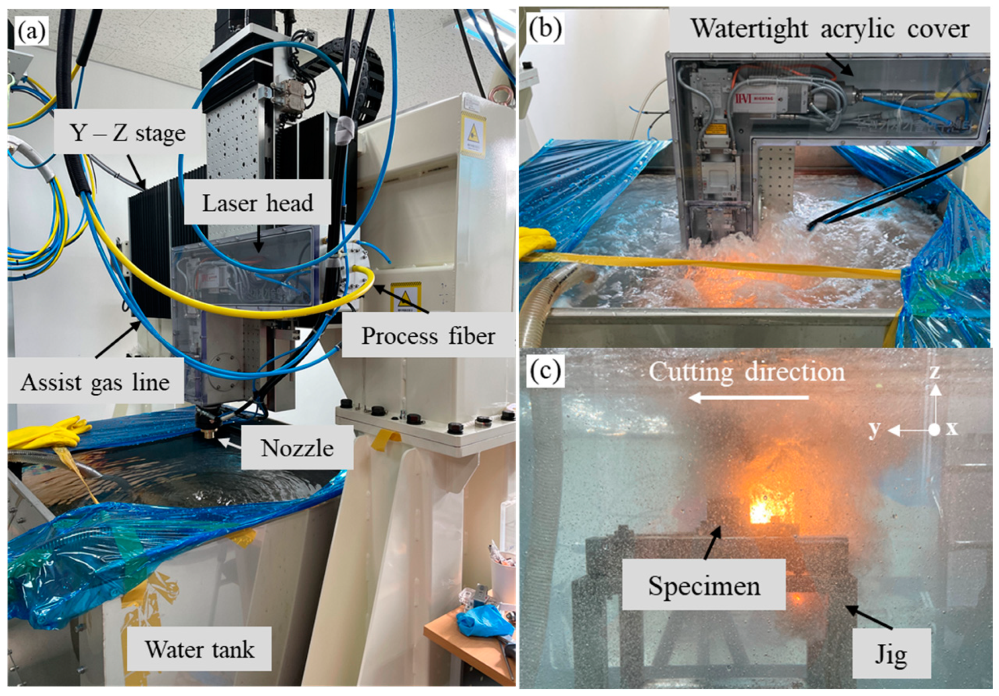
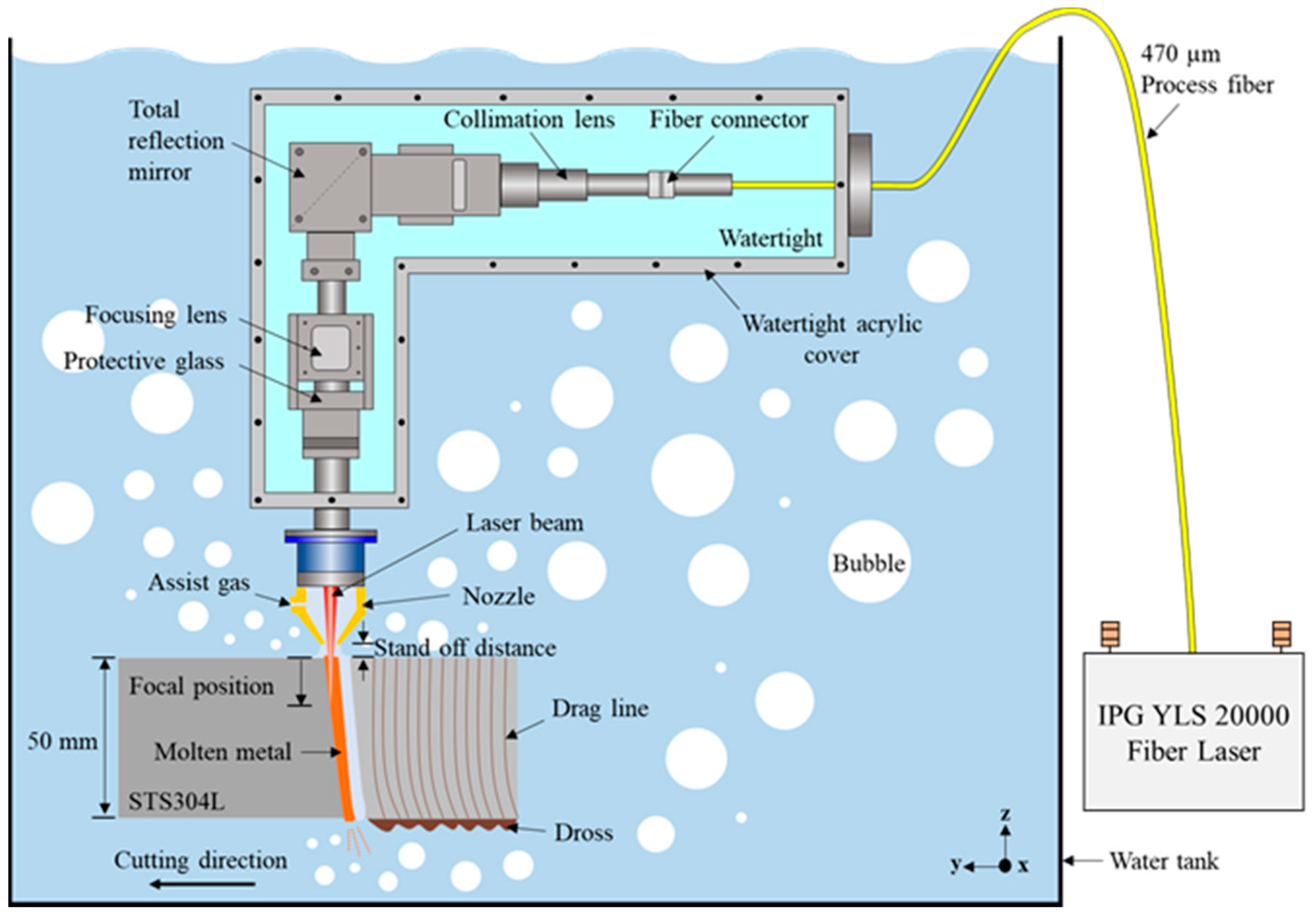
2.1. Experimental Materials and Methods

STS304L steel plates with a thickness of 50 mm, length of 100 mm, and width of 50 mm were used to prepare the experimental specimens. This material was selected because the main structure of the reactor internals (core support barrel assembly) on which underwater laser cutting is typically performed is composed of austenitic stainless steel. The chemical composition of the test specimen is presented in Table 1.
Figure 1 shows the configuration of the equipment used for the underwater laser cutting experiments, which consists of a laser system (YLS-2000; IPG Photonics Corporation, Oxford, MA, USA) and a water tank. The laser head is connected to a process fiber for long-distance transmission of the laser beam and an assist gas supply line for the discharge of molten metal and the securing of the laser beam path with a local dry cavity. A normal plate-type nozzle with a 3 mm diameter (dN) is used. The laser head is fixed to the Y-Z stage and moved along the cutting direction (Y) and inside the tank (Z). As shown in Figure 1b, the laser head is covered with a watertight acrylic cover for waterproofing. Additionally, a jig is installed inside the tank to minimize specimen movement, resulting from the high gas pressure and vibration during laser cutting. On the jig, the specimen was placed at a water depth of 300 mm (Figure 1c).
As shown in Figure 2, the specimen length in the cutting direction was 50 mm, but the specimen was laser-cut at a length of 40 mm, starting from its tip. To improve the cutting performance, the initial 15 mm section was provided with a specimen-preheating section and was cut at a low speed of 5 mm/min, while the remaining 25 mm section was cut at the set speed. As shown in Figure 3, the laser beam diameter at the focal position was 470 μm, and the stand-off distance, which is the distance from the nozzle tip to the specimen surface, was 1 mm. Nitrogen was used as the assist gas, and it was supplied at a pressure (PG) of 10 bar. The focal position (fd), which was the primary parameter considered in this experiment, was set inside the specimen. The laser power (P) was varied from 7 to 13 kW, while the cutting speed (v) was varied from 30 to 150 mm/min.

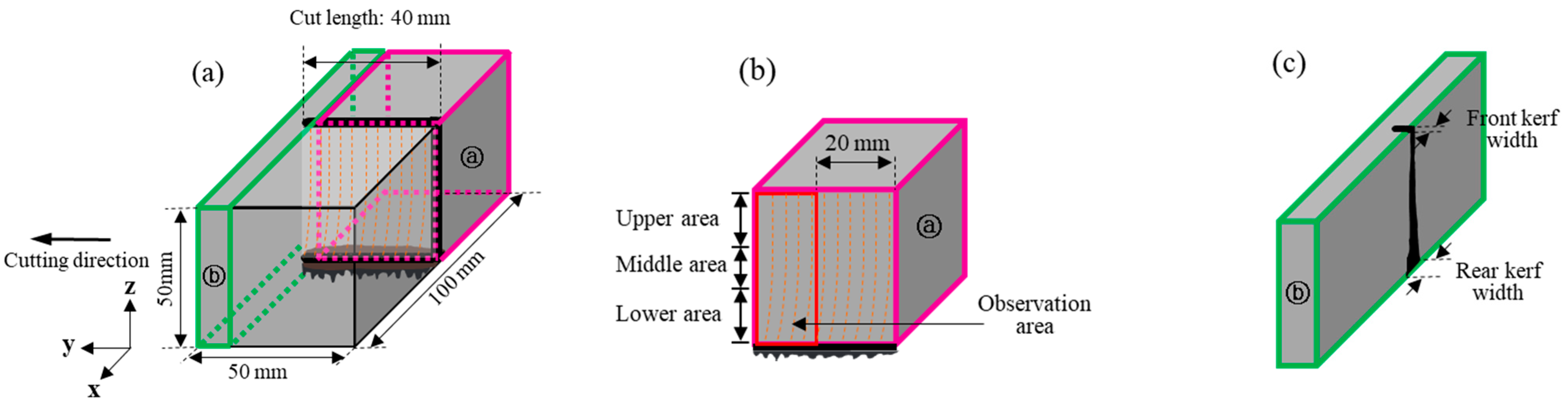
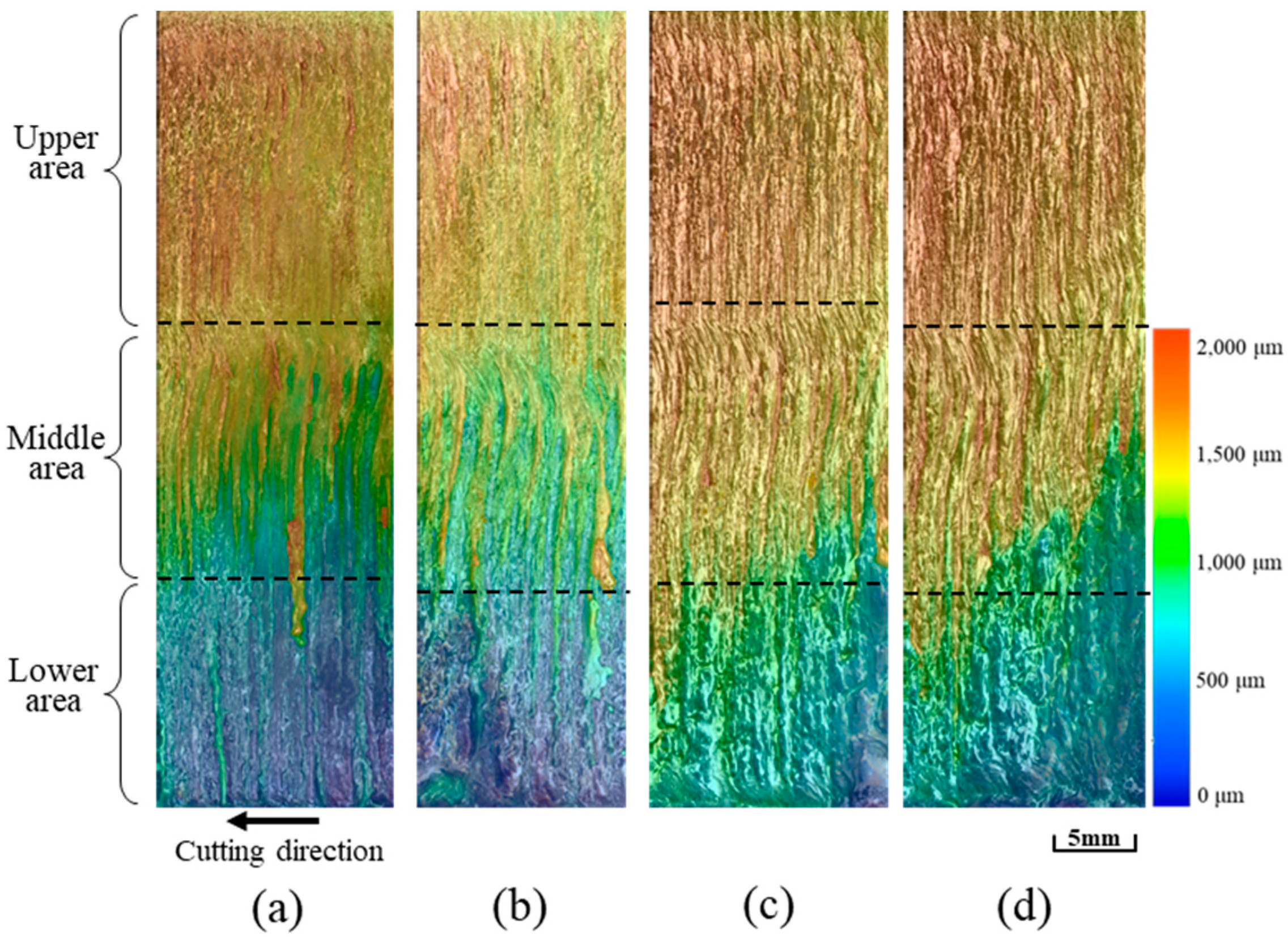
2.2. Laser Cutting Quality Analysis Methods

The front and rear surfaces, cutting surface, and cross-section of the specimen were observed to analyze the cutting quality. The cutting surface shows a characteristic periodic striation repetition and can be divided into three regions according to the shape of the drag line: the upper area, where the cutting by the laser beam is dominant; the middle area, where the melting is dominant near the focal position; and the lower area, where the cutting by the heat transfer of the molten metal is dominant.
The morphology of the cutting surface was observed using a high-resolution optical 3D surface microscope (VHX-7000; KEYENCE Corporation, Osaka, Japan). The length of each drag line area was measured, and line roughness was measured along the depth direction (Z) of the cutting surface.
The asperity of the cutting surface was visually inspected based on the topographic color distribution of the cutting surface. The cross-section observed perpendicular to the cutting direction, 35 mm away from the starting point of the cutting, was measured along with the front- and rear-surface kerf widths. The taper value, which indicates the difference between the front- and rear-surface kerf widths, was also calculated and compared with each cutting parameter.
In this study, the low-drag line roughness and low-taper value of the cutting surface, observed upon minimizing the laser heat input to the cutting surface, indicated excellent cutting quality based on the foregoing analysis.

3. Results and Discussions

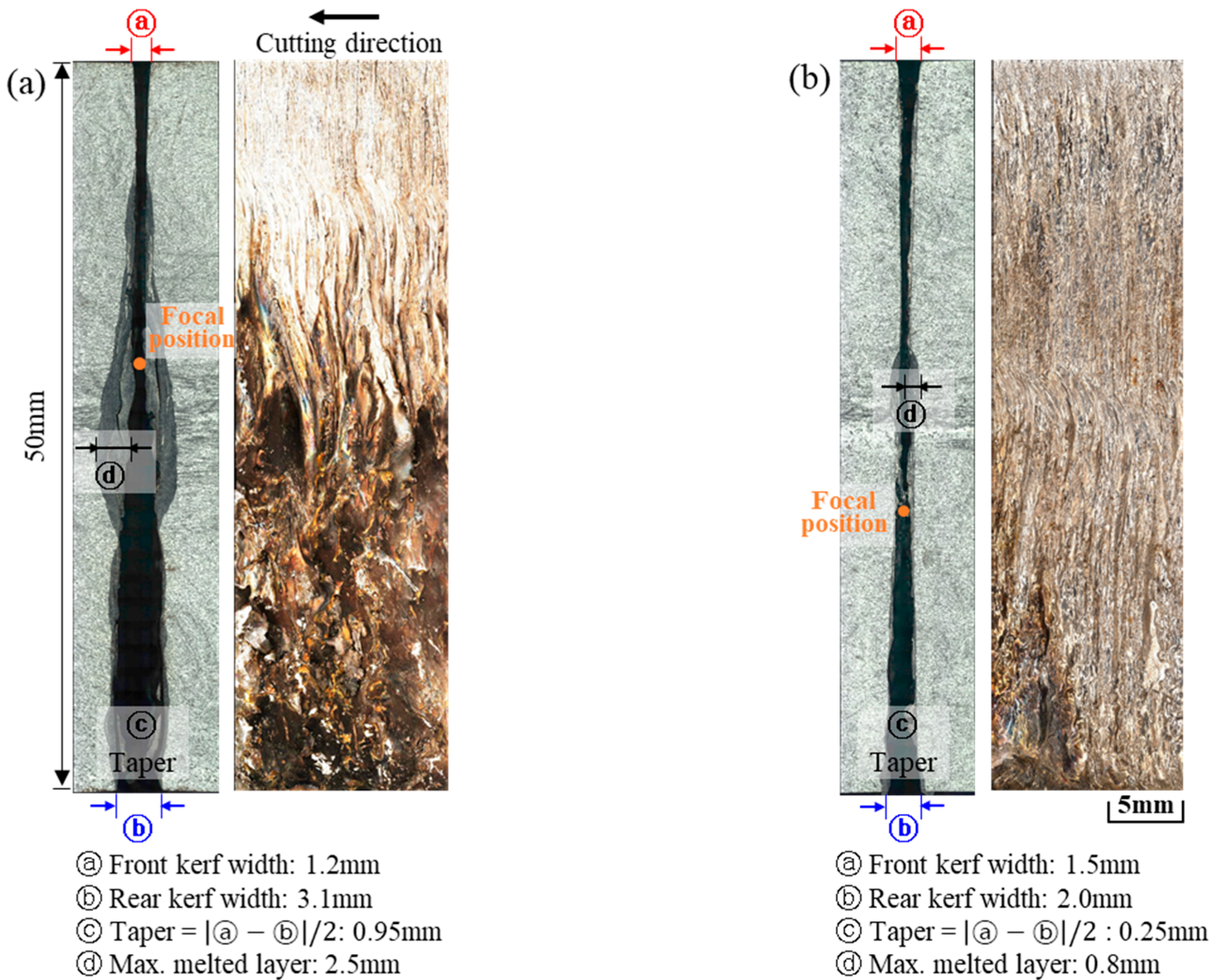
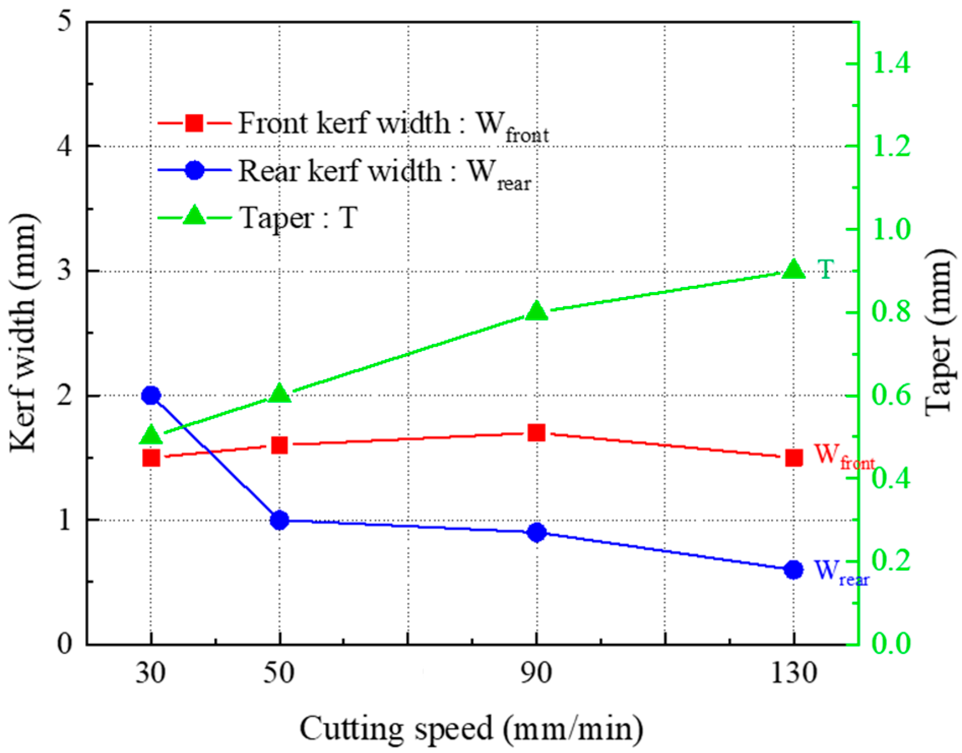
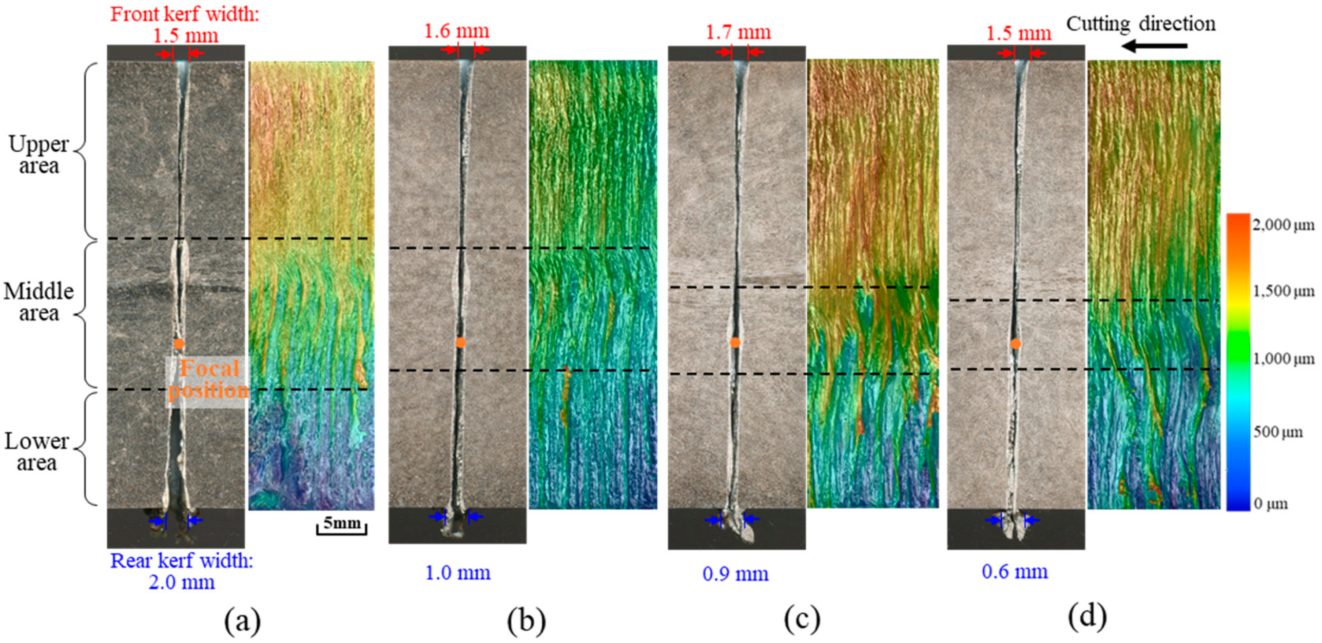
3.1. Effects of Focal Position on Kerf Width

An earlier study showed that during the laser cutting of stainless steel, the cutting quality is improved when the focal position is located further inside the material [33]. However, because the study was not conducted in an underwater environment, we examined the effect of the focal position during underwater laser cutting. When the focal position was located near the front surface of the specimen, non-cut or poor cutting surfaces were obtained; when the focal position was located too far inside the material, the cutting experiments were impossible to perform owing to interference from the optical system equipment. Therefore, in this study, we compared the characteristics of underwater laser-cut specimens at focal positions of −20 mm and −30 mm.
Figure 4 shows the cross-section and the cutting surface of specimens for different focal positions. Based on a comparison of the kerf widths, the −20 mm focal position led to a narrower front-surface kerf and a wider rear-surface kerf than the −30 mm position. Under the −20 mm condition, the focal position was located closer to the front surface of the specimen than it was under the −30 mm condition; this resulted in a relatively smaller laser beam diameter irradiating the specimen, and consequently, a narrower front-surface kerf. However, owing to the narrow front-surface kerf, the assist gas inflow was restrained, and the molten metal discharge was stagnant; this resulted in excessive quantities of molten material, particularly near the depth of focus, which increased the temperature inside the material and widened the rear-surface kerf. In addition, the maximum thickness of the melted layer formed was relatively large at the −20 mm focal position. By contrast, under the −30 mm condition, the laser beam diameter irradiating the surface of the specimen became relatively larger, resulting in a wider front-surface kerf. This facilitated the inflow of assist gas and the discharge of molten metal, resulting in less melting at the depth of focus and a narrower rear-surface kerf. Consequently, the taper value, which indicates the difference between the front- and rear-surface kerf widths, decreased for the −30 mm focal position.
Based on a comparison of the drag lines for the two conditions, an appropriate drag line was formed in the upper area of the cutting surface, where melting by the laser beam was dominant for the −20 mm focal position, owing to the previously mentioned reasons; however, an unstable drag line was formed in the middle, and a rough cutting surface was formed at the lower area. By contrast, for the −30 mm focal position, the drag line in the upper area became longer owing to the unhampered discharge of molten metal, and a generally satisfactory cutting surface was formed.
When the front- and rear-surface kerf widths, taper values, and cutting surface shapes were all considered, the cutting quality achieved with the −30 mm focal position was superior.

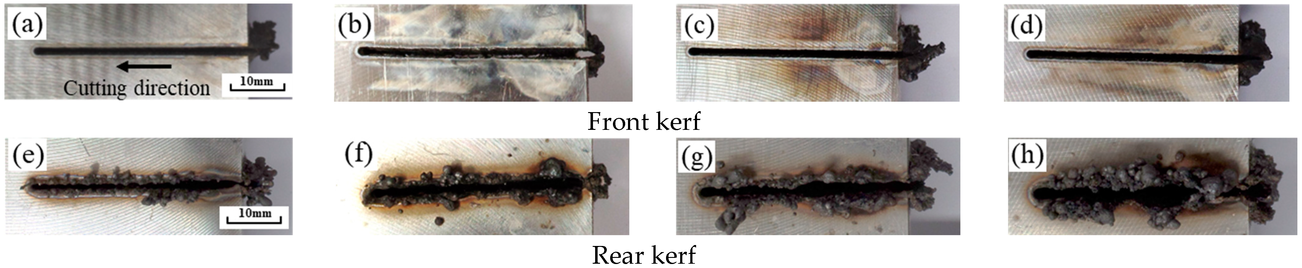
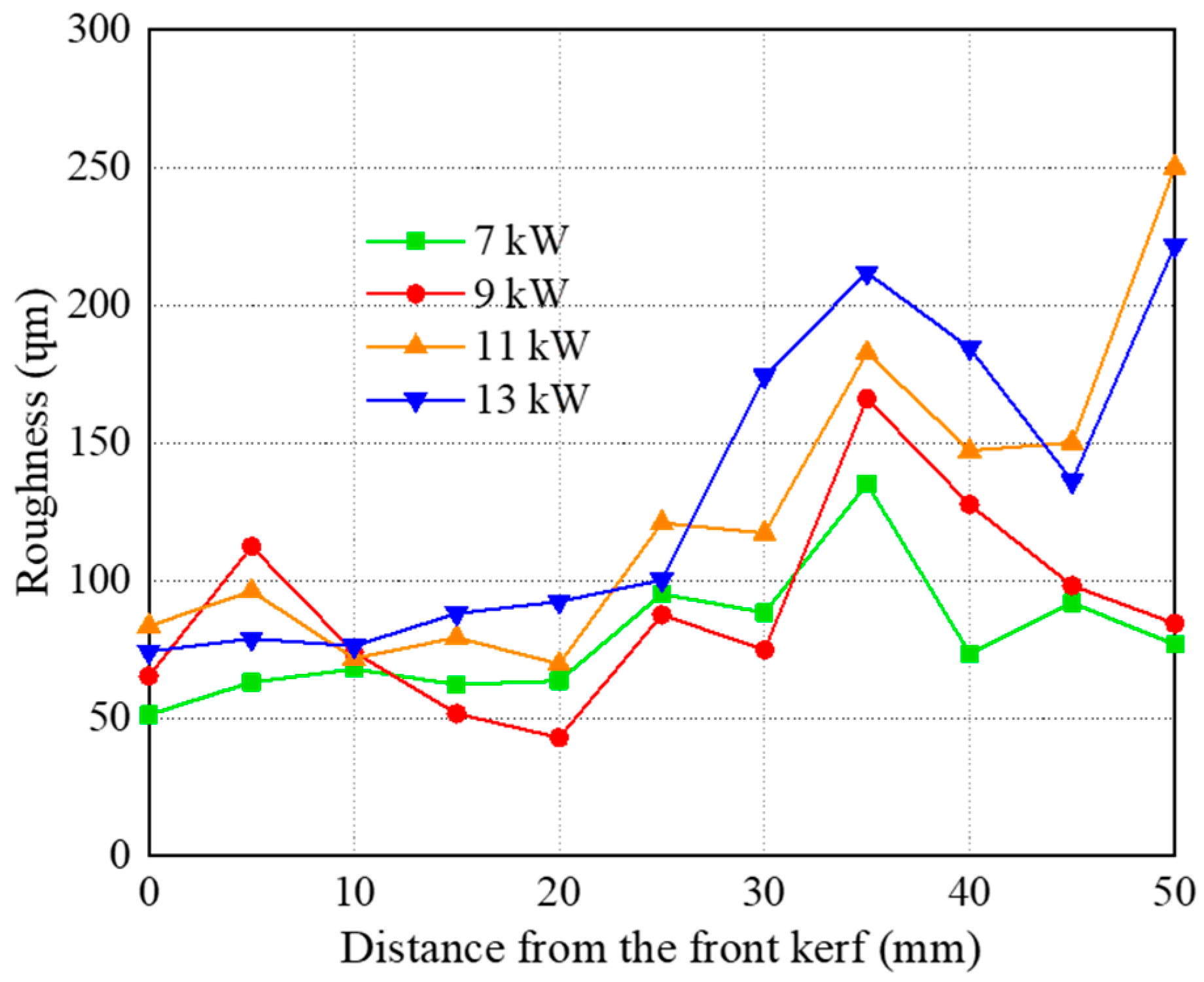
3.2. Effects of Laser Power on Cutting Surface Morphology

To examine the effect of the laser power on underwater laser cutting, the focal position was fixed at −30 mm, and the laser power was varied from 7 to 13 kW at 2 kW intervals. The front- and rear-surface kerf shapes, the kerf width and taper values, topographic color distribution of the cutting surface, and the measured roughness of the drag line are shown in Figure 4, Figure 5, Figure 6 and Figure 7. The variation in the front- and rear-surface kerf shapes with laser power is illustrated in Figure 5, which shows that the shape of the front-surface kerf did not change regardless of the laser power. However, upon comparing the rear-surface kerf shapes, the rear-surface kerf width tended to increase with the laser power owing to the increase in the heat input to the material. Furthermore, the quantity of the molten metal increased, and the amount of dross that adhered to the backside tended to increase as well.
This can be quantitatively confirmed from Figure 6, which plots the changes in kerf width. As the focal position was not changed, the front-surface kerf width was generally similar regardless of the laser power, while the rear-surface kerf width increased with the laser power. Therefore, the taper value, which represents the difference between the front- and rear-surface kerf widths, was the lowest under the 9 kW power condition.
Figure 7 shows the shape of the cutting surface according to the laser power, with similar drag line lengths and surface shapes at the upper, middle, and lower areas under all conditions. However, as the laser power increases, the unevenness of the drag line becomes more conspicuous, and the surface roughness of the drag line (Figure 8) also exhibits an increasing trend in general. This can be attributed to the relatively constant front-surface kerf width, even though the amount of melting inside the material increases with laser power. The higher the laser power, the higher the assist gas mass flux required. However, with the same front-surface kerf width, the assist gas inflow remains unchanged; hence, the molten metal discharge is hampered. This ultimately increases the roughness of the drag line.
The best cutting quality was obtained with a laser power of 9 kW, considering the front- and rear-surface kerf widths, taper value, and cutting surface shape and roughness.

3.3. Variation in the Drag Line length with Laser Cutting Speed

Based on the previous experiment, we conducted other experiments, changing the cutting speeds to 30, 50, 90, 130, and 150 mm/min at the focal position of −30 mm and the laser power of 9 kW. At the cutting speed of 150 mm/min, the material was not completely cut, owing to a delay in cutting. Therefore, the results for cutting speeds up to 130 mm/min were compared and are shown in Figure 8 and Figure 9.
Figure 9 shows the front- and rear-surface kerf widths and taper values as functions of the laser cutting speed. The front-surface kerf widths were generally similar for all conditions, and no clear trend could be observed with respect to the parameters. However, the rear-surface kerf width tended to decrease as the laser cutting speed increased. This is because the mass flux of the assist gas into the kerf decreased with the heat input owing to the high speed, and the molten metal was not completely discharged. Therefore, the smallest difference between the front- and rear-surface kerf widths was at a cutting speed of 30 mm/min.
Figure 10 shows the cross-section and topographic color distribution of the cutting surface at different laser cutting speeds. As the cutting speed increased, the length of the drag line gradually decreased in the middle area, which can be observed from the cross-section and the cutting surface. The drag line in the middle area indicates the region created when a large quantity of metal is melted near the depth of focus and the melt flow direction is changed from downward to partially backward. This decrease in the drag line length in the middle area can be attributed to the increase in cutting speed, the decrease in the corresponding heat input, as well as the reduced effect of the depth of focus. The roughness of the cutting surface, which can be confirmed based on the topographic color distribution, increased as the mass flux of the assist gas into the kerf decreased with increasing cutting speed.
These results using a stand-off distance of 1 mm were compared with Shin et al.’s study [25] conducted under the condition of a standoff distance of 10 mm. As a result, it was possible to obtain a high-quality cutting surface with a relatively small taper and low roughness of the cutting surface as the inflow of the assist gas into the kerf was increased.

4. Conclusions

In this study, the underwater laser cutting of 50 mm-thick STS304L specimens was performed while varying the key parameters of the laser beam to obtain a high-quality cutting surface. The technique employed is applicable for the decommissioning of nuclear power plant structures. The following conclusions were drawn by analyzing the changes in the kerf width, drag line, and roughness of the laser-cut specimens with respect to the cutting parameters:
(1) To understand the effect of the focal position of the laser beam on the cutting quality, underwater laser cutting was performed at focal positions fd = −20 mm and fd = −30 mm. A larger front-surface kerf was observed when the diameter of the laser beam irradiated on the specimen surface was relatively large at fd = −30 mm. This facilitated the discharge of the molten metal owing to the relatively large inflow of the assist gas, resulting in a generally satisfactory cut formation;
(2) Underwater laser cutting was performed while varying the laser power P from 7 kW to 13 kW. The results indicated that the front-surface kerf width changed minimally as the laser power increased, but the rear-surface kerf became wider owing to the increased melting caused by the increased heat input. However, sufficient molten metal could not be discharged, causing an increased drag line roughness. Thus, the best cutting quality was obtained when P = 9 kW;
(3) The cutting speed during underwater laser cutting considerably influences the heat input and the mass flux of the assist gas; as the cutting speed increases, the heat input and the mass flux of the assist gas decrease, the rear-surface kerf width decreases, and the drag line roughness increases because the molten metal is not smoothly discharged.
(4) Consequently, underwater laser cutting was possible up to a cutting speed of v = 130 mm/min under fd = −30 mm and P = 9 kW; however, the best-quality cutting surface was obtained under v = 30 mm/min.
In the future, we plan to study the effects of changes in the assist gas pressure, stand-off distance, and nozzle shape during underwater laser cutting, as well as the cutting characteristics of stainless steel with increasing thickness.

Author Contributions

Conceptualization, K.K. and J.-D.K.; methodology, K.K. and J.-D.K.; validation, K.K., M.-K.S. and J.-D.K.; investigation, K.K. and S.-J.L.; resources, S.-J.L., D.S., J.S. and J.-D.K.; writing—original draft preparation, K.K.; writing—review and editing, M.-K.S. and J.-D.K.; visualization, K.K.; supervision, J.-D.K.; project administration, J.-D.K.; funding acquisition, J.-D.K. All authors have read and agreed to the published version of the manuscript.

Funding

This research received no external funding.

Acknowledgments

This paper was supported by the National Research Council of Science and Technology (Project number: NK232A, 2021, KOREA) and by the Korea Institute for Advancement of Technology (KIAT) grant funded by the Korean Government (MOTIE) (P0008763, The Competency Development Program for Industry Specialist), and is a revised and expanded version of a paper entitled “Fundamental study for underwater cutting of 50 mm thick stainless steel using fiber laser in nuclear decommissioning” presented at the International Symposium on Marine Engineering and Technology 2021.

Conflicts of Interest

No conflict of interest.

References

  1. International Atomic Energy Agency. Nuclear Power Reactors in the World; International Atomic Energy Agency: Vienna, Austria, 2021; ISBN 9789201244215. [Google Scholar]
  2. Park, S.J.; Byon, J.; Ban, D.H.; Lee, S.; Sohn, W.; Ahn, S. Derivation of Preliminary Derived Concentration Guideline Level (DCGL) by Reuse Scenario for Kori Unit 1 Using RESRAD-BUILD. Nucl. Eng. Technol. 2020, 52, 1231–1242. [Google Scholar] [CrossRef]
  3. Cho, D.W.; Choi, J.S.; Lee, S.J.; Shin, D.S. Analysis of Gas Flow Behavior in the Laser Cutting Process Using the Schlieren Method and Image Processing. J. Weld. Join. 2020, 38, 569–575. [Google Scholar] [CrossRef]
  4. Yanagihara, S.; Ashida, S.; Usui, H. Dismantling of JPDR Internals Using Underwater Plasma Arc Cutting Technique Operated by Robotic Manipulator. J. Nucl. Sci. Technol. 1988, 25, 891–894. [Google Scholar] [CrossRef]
  5. Kim, C.-S.; Park, D.-W.; Yang, Y.-J. Development of an Automatic Shell Plate Hole Generation System Using AVEVA Marine. J. Adv. Mar. Eng. Technol. 2020, 44, 196–202. [Google Scholar] [CrossRef]
  6. Kutsuna, H.; Iwai, H.; Mizui, H.; Kadowaki, H.; Nakamura, Y. Document Collection of the 28th Technical Special Committee on Fugen Decommissioning (Document No. JAEA-Review 2013-049). Fug. Decommissioning Eng. Cent. Tsuruga Head 2014. [Google Scholar] [CrossRef]
  7. Tamura, K.; Ishigami, R.; Yamagishi, R. Laser Cutting of Thick Steel Plates and Simulated Steel Components Using a 30 KW Fiber Laser. J. Nucl. Sci. Technol. 2016, 53, 916–920. [Google Scholar] [CrossRef]
  8. Tamura, K.; Yamagishi, R. Laser Cutting Conditions for Steel Plates Having a Thickness of More than 100 Mm Using a 30 KW Fiber Laser for Nuclear Decommissioning. Mech. Eng. J. 2016, 3, 15.00590.1–15.00590.9. [Google Scholar] [CrossRef]
  9. Tamura, K.; Yamagishi, R. Observation of the Molten Metal Behaviors during the Laser Cutting of Thick Steel Specimens Using Attenuated Process Images. J. Nucl. Sci. Technol. 2017, 54, 655–661. [Google Scholar] [CrossRef]
  10. Tamura, K.; Toyama, S. Laser Cutting Performances for Thick Steel Specimens Studied by Molten Metal Removal Conditions. J. Nucl. Sci. Technol. 2017, 54, 1011–1017. [Google Scholar] [CrossRef]
  11. Hilton, P.; Khan, A. New Developments in Laser Cutting for Nuclear Decommissioning. In Proceedings of the Annual Waste Management (WM) Conference, Phoenix, AZ, USA, 2–4 March 2014. [Google Scholar]
  12. Sato, S.; Inaba, T.; Inose, K.; Matsumoto, N.; Sakakibara, Y. Development of Underwater Laser Cutting Technology. Dekomisshoningu Giho 2015, 52, 55–59. [Google Scholar]
  13. Steen, W.M.; Mazumder, J. Laser Material Processing; Springer Science & Business Media: Berlin, Germany, 2010; ISBN 1849960623. [Google Scholar]
  14. Hilton, P.A.; Khan, A. Underwater Cutting Using a 1 μm Laser Source. J. Laser Appl. 2015, 27, 32013. [Google Scholar] [CrossRef]
  15. Parshin, S.; Levchenko, A.; Wang, P.; Maystro, A. Mathematical Analysis of the Influence of the Flux-Cored Wire Chemical Composition on the Electrical Parameters and Quality in the Underwater Wet Cutting. Adv. Mater. Sci. 2021, 21, 77–89. [Google Scholar] [CrossRef]
  16. Li, W.; Zhao, J.; Wang, J.; Wang, J.; Jia, H.; Li, Z.; Maksimov, S.Y. Research on Arc Cutting Mechanism and Procedure of Flux-Cored Cutting Wire in Water. Int. J. Adv. Manuf. Technol. 2018, 98, 2895–2904. [Google Scholar] [CrossRef]
  17. Shin, J.S.; Oh, S.Y.; Park, S.; Park, H.; Kim, T.S.; Lee, L.; Kim, Y.; Lee, J. Underwater Laser Cutting of Stainless Steel up to 100 Mm Thick for Dismantling Application in Nuclear Power Plants. Ann. Nucl. Energy 2020, 147, 107655. [Google Scholar] [CrossRef]
  18. Fu, Y.; Guo, N.; Cheng, Q.; Zhang, D.; Feng, J. Underwater Laser Welding for 304 Stainless Steel with Filler Wire. J. Mater. Res. Technol. 2020, 9, 15648–15661. [Google Scholar] [CrossRef]
  19. Fu, Y.; Guo, N.; Zhu, B.; Shi, X.; Feng, J. Microstructure and Properties of Underwater Laser Welding of TC4 Titanium Alloy. J. Mater. Process. Technol. 2020, 275, 116372. [Google Scholar] [CrossRef]
  20. Morita, I.; Owaki, K.; Yamaoka, H.; Kim, C.C. Study of Underwater Laser Welding Repair Technology. Weld. World 2006, 50, 37–43. [Google Scholar] [CrossRef]
  21. Yoda, M.; Tamura, M.; Fukuda, T.; Shiihara, K.; Sudo, K.; Maehara, T.; Morishima, Y.; Kato, H.; Ichikawa, H. Underwater Laser Beam Welding for Nuclear Reactors. Int. Conf. Nucl. Eng. Proc. ICONE 2012, 1, 191–195. [Google Scholar]
  22. SANO, Y.; MUKAI, N.; MAKINO, Y.; TAMURA, M.; OBATA, M.; YODA, M.; SHIMA, S.; KATO, H. Enhancement of Surface Properties of Metal Materials by Underwater Laser Processing. Rev. Laser Eng. 2008, 36, 1195–1198. [Google Scholar] [CrossRef] [Green Version]
  23. Kang, Y.; Park, S.; Oh, C.; Lee, S.; Kang, S. Effect of Post-Weld Heat Treatment Temperature on the Mechanical Properties and Microstructure of Weld Heat-Affected Zone of Low-Alloy Steel for Nuclear Reactor Pressure Vessel. J. Weld. Join. 2020, 38, 24–32. [Google Scholar] [CrossRef] [Green Version]
  24. Jun, S.Y.; Im, S.Y.; Moon, J.; Lee, C.H.; Hong, H.U. Technical Issues in Fusion Welding of Reduced Activation Ferritic/Martensitic Steels for Nuclear Fusion Reactors. J. Weld. Join. 2020, 38, 47–55. [Google Scholar] [CrossRef] [Green Version]
  25. Shin, J.S.; Oh, S.Y.; Park, H.; Kim, T.S.; Lee, L.; Chung, C.M.; Lee, J. Underwater Cutting of 50 and 60 mm Thick Stainless Steel Plates Using a 6-KW Fiber Laser for Dismantling Nuclear Facilities. Opt. Laser Technol. 2019, 115, 1–8. [Google Scholar] [CrossRef]
  26. Wandera, C.; Kujanpää, V. Optimization of Parameters for Fibre Laser Cutting of a 10 Mm Stainless Steel Plate. Proc. Inst. Mech. Eng. Part B J. Eng. Manuf. 2011, 225, 641–649. [Google Scholar] [CrossRef]
  27. Lopez, A.B.; Assunção, E.; Quintino, L.; Blackburn, J.; Khan, A. High-Power Fiber Laser Cutting Parameter Optimization for Nuclear Decommissioning. Nucl. Eng. Technol. 2017, 49, 865–872. [Google Scholar] [CrossRef]
  28. Oh, S.Y.; Shin, J.S.; Kim, T.S.; Park, H.; Lee, L.; Chung, C.M.; Lee, J. Effect of Nozzle Types on the Laser Cutting Performance for 60-Mm-Thick Stainless Steel. Opt. Laser Technol. 2019, 119, 105607. [Google Scholar] [CrossRef]
  29. Oh, S.Y.; Shin, J.S.; Park, S.; Kim, T.S.; Park, H.; Lee, L.; Lee, J. Underwater Laser Cutting of Thick Stainless Steel Blocks Using Single and Dual Nozzles. Opt. Laser Technol. 2021, 136, 106757. [Google Scholar] [CrossRef]
  30. Shin, J.S.; Oh, S.Y.; Park, H.; Chung, C.M.; Seon, S.; Kim, T.S.; Lee, L.; Choi, B.S.; Moon, J.K. High-Speed Fiber Laser Cutting of Thick Stainless Steel for Dismantling Tasks. Opt. Laser Technol. 2017, 94, 244–247. [Google Scholar] [CrossRef]
  31. Shin, J.S.; Oh, S.Y.; Park, S.K.; Park, H.; Lee, J. Improved Underwater Laser Cutting of Thick Steel Plates through Initial Oblique Cutting. Opt. Laser Technol. 2021, 141, 107120. [Google Scholar] [CrossRef]
  32. Kim, K.; Song, M.; Kim, J.; Lee, S.; Shin, D.; Jeong, J.; Kim, J. Fundamental study for underwater cutting of 50mm thick stainless steel using fiber laser in nuclear decommissioning. In Proceedings of the International Symposium on Manufacturing Science and Engineeering Technology, Busan, Korea, 21–22 October 2021. [Google Scholar]
  33. Song, M.-K.; Kim, J.-D.; Shin, D.-S.; Lee, S.-J.; Cho, D.-W. Effect of Focal Position on Cut Surface Quality in Laser Cutting of 50-Mm Thick Stainless Steel. Int. J. Mod. Phys. B 2021, 35, 2140018. [Google Scholar] [CrossRef]
Figure 1. Experimental setup; (a) Laser head & water tank, (b) Laser head, (c) Cutting process.
Applsci 12 00495 g001
Figure 2. Schematic diagrams of specimen collection of cutting surface and cross-section; (a) Cut specimen, (b) Cutting surface, (c) Cross-section.
Applsci 12 00495 g002
Figure 3. Schematic diagram of underwater laser cutting process.
Applsci 12 00495 g003
Figure 4. Cut cross-section and cutting surface of specimens according to the focal position; (a) fd = −20 mm, (b) fd = −30 mm (Processing conditions: P = 9 kW, v = 30 mm/min, dN = 3 mm, PG = 10 bar, Nozzle type = Normal plate).
Applsci 12 00495 g004
Figure 5. Front and rear surface of specimen according to focal position; (a,e) P = 7 kW, (b,f) P = 9 kW, (c,g) P = 11 kW, (d,h) P = 13 kW (Processing conditions: fd = −30 mm, v = 30 mm/min, dN = 3 mm, PG = 10 bar, Nozzle type = Normal plate).
Applsci 12 00495 g005
Figure 6. Variation in kerf width and taper according to the laser power.
Applsci 12 00495 g006
Figure 7. Topographic color distribution of cutting surface according to the laser power; (a) P = 7 kW, (b) P = 9 kW, (c) P = 11 kW, (d) P = 13 kW (Processing conditions: fd = −30 mm, v = 30 mm/min, dN = 3 mm, PG = 10 bar, Nozzle type = Normal plate).
Applsci 12 00495 g007
Figure 8. Variation in roughness by the distance from the front surface according to the laser power.
Applsci 12 00495 g008
Figure 9. Variation in kerf width and taper according to the cutting speed.
Applsci 12 00495 g009
Figure 10. Cross-section and topographic color distribution of cutting surface according to the cutting speed; (a) v = 30 mm/min, (b) v = 50 mm/min, (c) v = 90 mm/min, (d) v = 130 mm/min (Processing conditions: fd = −30 mm, P = 9 kW, dN = 3 mm, PG = 10 bar, Nozzle type = Normal plate).
Applsci 12 00495 g010
Table 1. Chemical composition of STS304L (wt %) received from the manufacturer of the test specimen.
ElementFeCSiMnPSCrNiMoNCoCu
Mass fractionBase0.0220.391.640.030.00418.168.040.140.0670.220.28
Publisher’s Note: MDPI stays neutral with regard to jurisdictional claims in published maps and institutional affiliations.

