Article

De-Powdering Effect of Foundry Sand for Cement Casting

1
Industrial Environment Green Deal Agency, Korea Institute of Industrial Technology, Ulsan 44413, Korea
2
Department of Material Science and Engineering, Pusan National University, Busan 46241, Korea
3
Department of Materials Science and Engineering, Korea Advanced Institute of Science and Technology, Daejeon 34141, Korea
*
Authors to whom correspondence should be addressed.
Appl. Sci. 2022, 12(1), 266; https://doi.org/10.3390/app12010266
Submission received: 17 November 2021 / Revised: 17 December 2021 / Accepted: 20 December 2021 / Published: 28 December 2021

Abstract

:
With the development of the powder bed 3D printing process, sand casting can be performed with methods that are more advanced than the traditional ones, thus enabling new research on applied materials. When sand is 3D-printed with cement as a binder, its casting performance is improved and sufficient thermal stability of conventional organic and inorganic binders is ensured. In this study, to ensure high resolution and strength in a physical and simple mixture of cement and sand, the compatibility for casting was confirmed using submicron-level cement with ingredients and sizes similar to commercial sand, which is uniformly controlled at 4 µm, instead of conventional sand. To enable quick 3D printing, calcium aluminate cement, which has quick binding properties, was used for high-temperature casting. The strength up to 6 h after hydration was compared to determine the curing rate of silica, mullite, and alumina sand containing cement components. By investigating the change in strength due to heat treatment and comparing the adhesion drop test results after powder bed formation, the material containing silica sand was determined as the most suitable for powder layer 3D printing for application to the mold.

1. Introduction

The advancements in the casting technology though the 3D printing process satisfies the price competitiveness and improvement in product performance in the sand casting market, thereby rapidly competing with the classic casting method [1]. Functional inorganic materials that can be used at high temperatures, such as castables, using existing cement binders, require high-temperature thermal stability for casting. Mixing cement and foundry sand not only prevents toxic emissions from conventional 3D printing operations, wherein organic and inorganic binders are mainly used, but also simplifies the post-processes [2,3].
The application of 3D printing to sand casting can lead to further innovation in the sand casting resolution as high-temperature compatibility of existing alumina cement and precise shape implementation are steadily investigated through differentiation [4,5,6,7]. Sand molds manufactured for casting using traditional casting methods can be easily accessed by applying conventional casting sand [8]. In 3D printing, mold manufacturing, whose resolution can be similar to that of commercial casting sand in the 3D printing of powder bed, has been commercialized and applied to large castings such as marine engine parts [1,9]. Studies have been conducted to overcome the limitations of shape manufacturing using a finer process to ensure surface resolution and dimensional stability by reducing the material size [10,11,12]
The resolution of 3D printing is ultimately determined by the uniformity and size (small) of the material, which can reduce the layer height. In recent studies, a uniform submicron particle size has been selected through a simple mixing process to solve the agglomeration of ceramic powder [13,14]. Alumina, mullite, and fumed silica are commercially used as high-temperature casting sands [15]. Refractory calcium aluminate cement (CAC) exhibits high strength and quick setting at the submicron level [16]. While it is important to ensure sufficient casting mold strength, strength adjustment is required after melting as well to ensure that the mold can be removed and the casting shape can be fully obtained [8,15]. Such intensity adjustment has become more necessary owing to the complex shape of the molded body in the increasingly detailed 3D printing market [17]. Additionally, it is essential to remove the mold without damaging the weak and fine parts of the inner cast [15,18].
In this study, the suitability of the handling strength of the mold was confirmed by comparing the formability of sand for casting at the submicron level considering powder bed 3D printing [5]. In order to select a sand with excellent castability and appropriate strength, the strength and phase changes due to heat treatment were checked. Finally, a sessile drop test was performed to verify the applicability of drop test to a powder bed, and the spreadability and strength were compared.

2. Method and Experiments

2.1. Mixed Powder Preparation

Silica (99% fused silica, DIGHEN Composite Material Technology Co., Ltd., Lianyungang, China), mullite (fused mullite (64.2 wt% Al2O3 and 36.8 wt% SiO2), DIGHEN Composite Material Technology Co., Ltd., Lianyungang, China), and alumina (fused alumina, DIGHEN Composite Material Technology Co., Ltd., Lianyungang, China) powders, which had an average particle size of 4 µm (Figure 1), were prepared as the raw sand materials for refractory purposes. The cement used as a binder for preparing the mold was made of CAC (HF80N, UNION Corp., Seoul, Korea) with quick-setting performance powder for fire resistance. The CAC had an average particle size of <4 µm (Figure 1). A water-based activator with 2% 2-pyrrolidone was used for preparing molded bodies and in powder bed tests. It was dried in a 100 °C oven for 24 h to ensure that it could sufficiently mix with the sand to prevent lumping; however, since it contained atmospheric moisture, it was lumpy and not easily mixable. Since the densities of sands were different, as shown in Table 1, the cement was mixed with each sand in a definite volume ratio. The prepared samples were mixed with 1 mm zirconia medium by horizontal ball milling for 2 h. The cube-shaped mold samples prepared from the mixtures of silica and CAC, mullite and CAC, and alumina and CAC were named S + C, M + C, and A + C, respectively.

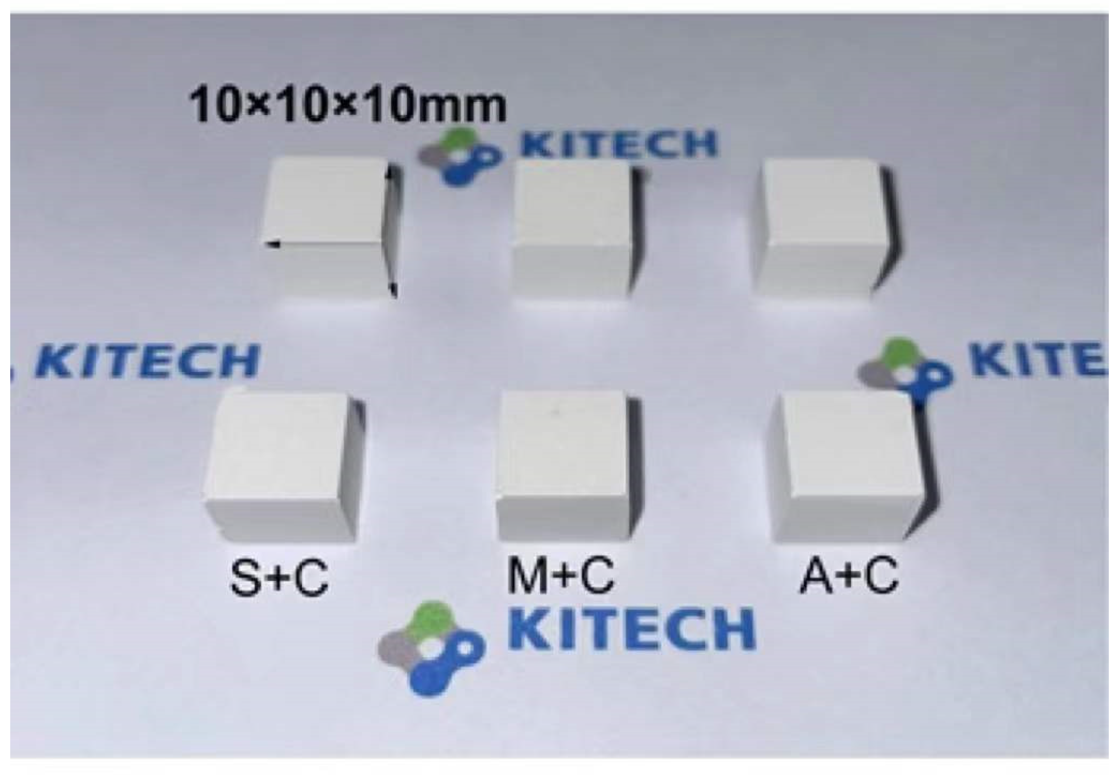
2.2. Molded Body Curing

Each sample mold was prepared with the same cross-sectional area to compare the strength of the unilateral pressure. To fix the size of each molded body, a 200-piece silicone mold, capable of 10 mm × 10 mm × 10 mm regular hexahedron molding, was prepared (Figure 2). In the powder sample, which was sufficiently mixed with CAC and sand, the activator was poured to hydrate and turn it into a slurry; the amount of activator required for hydrating the CAC was adjusted to ensure a uniform mixture. Previous studies have shown that the change in strength is insignificant when the amount of activator is sufficient. Therefore, the amount of activator was fixed at 40% to enable sufficient handling [19]. The slurry was sufficiently watery to flow down, and adequate internal air bubbles were removed using a negative pressure device; this slurry was then poured into a silicon frame and shook to prevent pores and ensure uniformity. The dish was then dried at room temperature for 6 h.

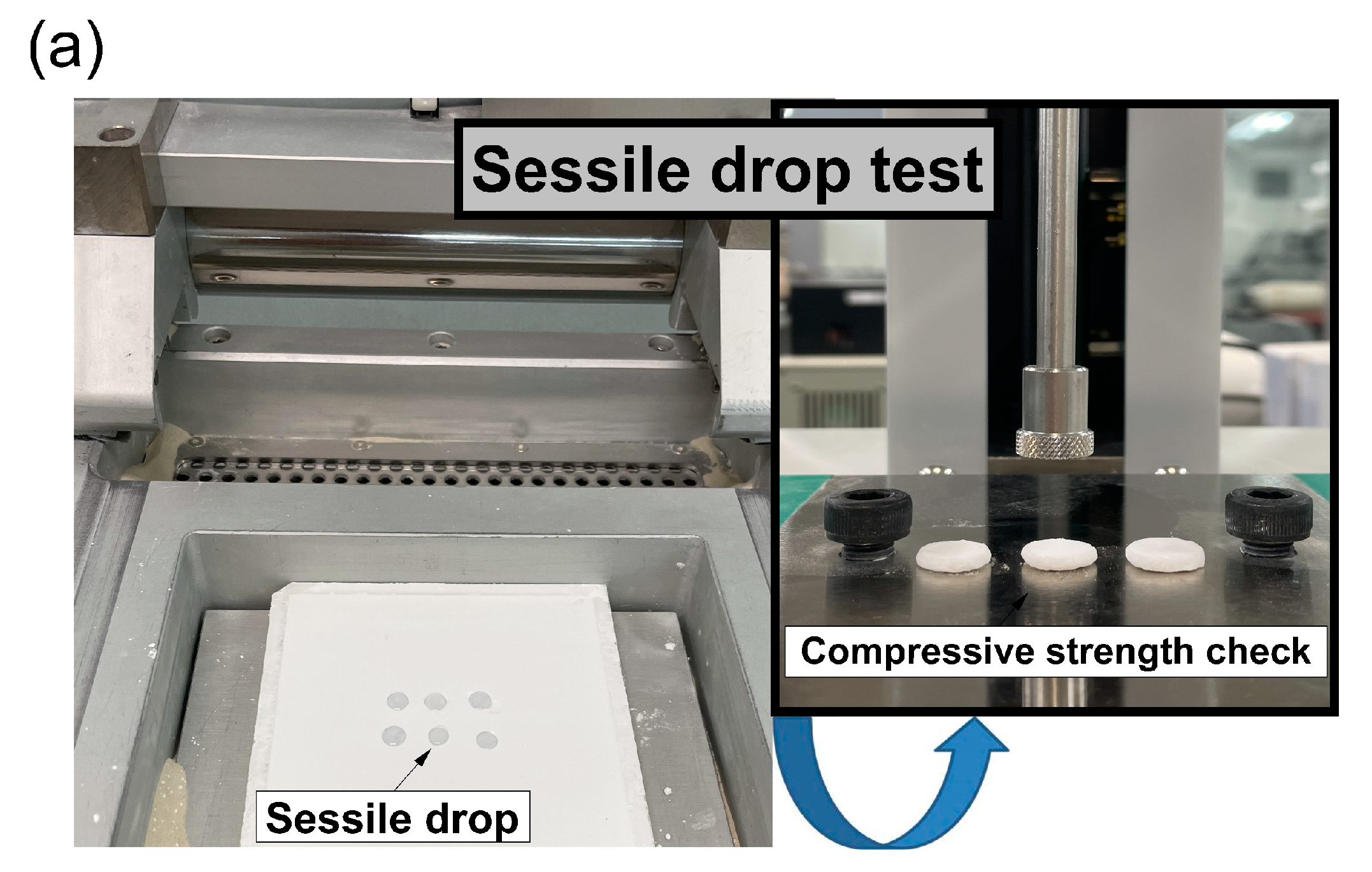
2.3. Sessile Drop Test

Powder bed recoating was performed using a sessile drop tester (Freeforms T150, SFS, Korea) to determine the powder bed formability. It was intended that the sessile drop tester make use of a layered surface, similar to a powder bed 3D printer. It consisted of a metal frame along the XY axis and steel rollers with a diameter of 35 mm, connected to a step motor. The axis movement and rotation of the metal roller were controlled using a driver and a speed controller, respectively, and it was installed on a rail without vibration to enable motion at a constant speed along the X axis. The recoating speed of the recoating device was 50–200 mm/s, which was fixed for a rotation speed of 20 rpm. In order to obtain the same packing density as an actual 3D printer, each powder was recoated to a thickness of 10 mm on a dense plastic plate.
The sessile drop test of fixed-size binder droplets on the powder bed surface was performed by pipetting 30 µL at a fixed height of 2 mm (slightly larger than the droplet size to avoid its contact with the powder interface). The droplet was positioned suitably such that the effect of gravity on the droplet was minimized.

2.4. Characterization

Avalanche angle testing was performed using the revolution method (revolution powder analyzer, Mercury Scientific Inc., Newtown, CT, USA). In this test, a tap volume of 100 cm3 was measured using a cup, which was filled and tapped until no more powder could be filled in it, and a sharp edge was used to remove the excess powder. The powder was then transferred to a cylindrical drum surrounded by a see-through glass window. The drum was configured to rotate at 0.3 rpm to minimize the effect of surface friction, and the flow behavior of the powder was analyzed using a digital camera. Avalanche angle measurements were averaged on the basis of 125 snapshots, for a total time of 120 s, for reliability. The uniaxial compressive strength was measured using a universal tester (MTS810, Material Test System Corp, Eden Prairie, MN, USA) with a cylindrical sample, which had a diameter, height, and fixed speed of 10 mm, 10 mm, and 0.2 mm/min, respectively. Thermogravimetric (TG) and differential scanning calorimetry (DSC) analyses were performed by heating the samples at 10 °C/min in an atmospheric environment using a thermal analyzer (STA449C/3/MFC/G, NETZSCH, Germany). The crystal phase of the 3D-printed template was profiled by X-ray diffraction (XRD, D/max Rigaku 2200V/PC, Japan).

3. Results and Discussion

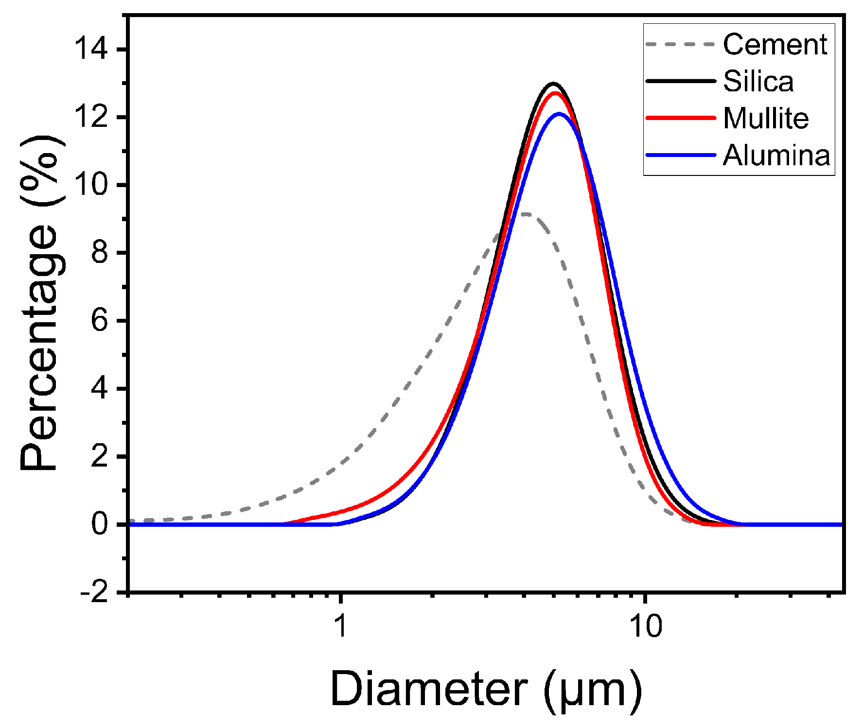
3.1. Powder Bed Property Evaluation

In a previous study, the droplet absorption time of the material on the layered surface in powder bed 3D printing was considered as an important parameter in evaluating the recoating possibility [20]. Therefore, in the 3D printing process, it is necessary to optimize the time taken by a droplet to fall on the powder interface and get absorbed [17]. In general commercial 3D printing, when powder is recoated, a new layered surface is formed in >5 s. Powder bed recoating was performed using a sessile drop tester to determine the absorption time of the activator. Figure 3a shows the droplet absorption time when the CAC content of each sand is increased in 5% volume ratio intervals. When the CAC content of every sand is >20% of the volume ratio, the droplet absorption time is <5 s. Figure 3b shows the changes in the flowability when the CAC content in each sand is increased in intervals of 5% by volume in avalanche angle testing. All sands show similar flowability changes depending on the CAC content. A flowability test was performed on each sample powder using the revolution method. The rotation of the drum resulted in the powder being carried along the sides of the drum until the drum could no longer support the powder weight, forming an avalanche. The avalanche angle was measured as the angle at which the powder was at its highest position before the avalanche began. A smaller avalanche angle indicates better flowability of the powder [14]. The standard deviation in the avalanche angle hardly changes up to 20% CAC content but rapidly increases at a volume ratio of ≥25%. Therefore, the experiment was performed at a constant CAC content (20%), which is smaller than the 25% cement volume ratio, thereby increasing the flowability variable.

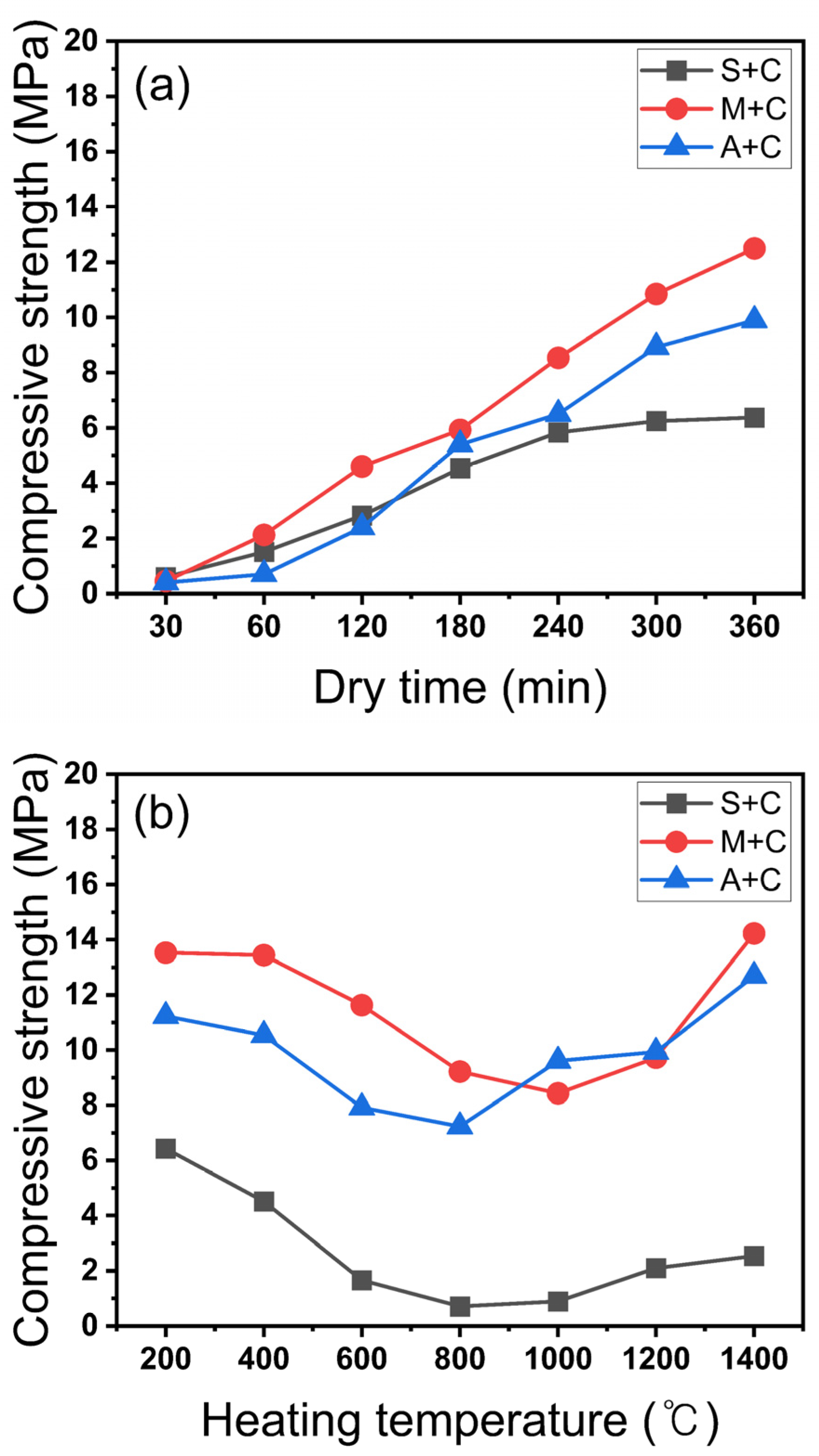
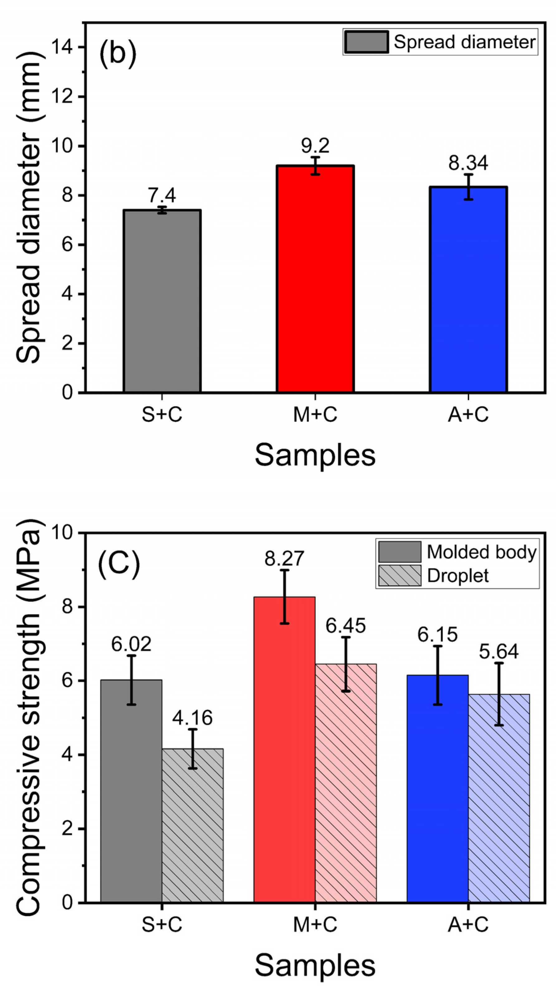
3.2. Physical Property Evaluation

The slurry that was poured into the silicone frame via quick binding of CAC completely fell off the frame after 30 min. Subsequently, the uniaxial compressive strength was measured at 1 h intervals to compare the curing rates (Figure 4a). To accurately evaluate the compressive strength, the average value obtained for 20 cube-shaped molded bodies was used for each evaluation.
As shown in Figure 4a, the S + C sample is cured after 4 h and its strength is 6.02 MPa after 4 h. In contrast, the M + C and A + C samples are not completely cured after 4 h. The highest strength of the additive-manufactured commercial molds using the same inorganic binder family, a silicate binder, was 2.5–4 MPa [10,21]. In every sample, the handling strength of the mold was satisfied at strengths of ≥4 MPa after 4 h of molding [7,15]. Therefore, a mold that can be treated with a curing time of 4 h (in powder bed 3D printing) is obtainable for application in rapid molding.
As can be seen in Figure 4b, all samples are hydrated even after 6 h of air drying and show slightly higher strengths. All samples show a sharp decrease in strength at 400 °C. Up to their lowest strengths, the S + C, M + C, and A + C samples show a reduction in strength of 88.9% (6.43 MPa to 0.71 MPa), 37.7% (14.49 MPa to 8.31 MPa), and 35.6% (12.23 MPa to 7.23 MPa), respectively. This affects the characteristics of CAC owing to the different sand types; CAC cement showed the same trend as a result of strength reduction in the temperature range 600–1200 °C [16,22,23,24]. In comparison, the strength of silica significantly decreased at 600 °C, and the strength recovery was slow at higher heating temperatures [22]. On the other hand, alumina rapidly recovered its strength after the lowest strength at 800 °C, whereas mullite showed a decrease in strength after the recovery at 1000 °C. This is a result of the change in pores due to sintering [25,26,27].

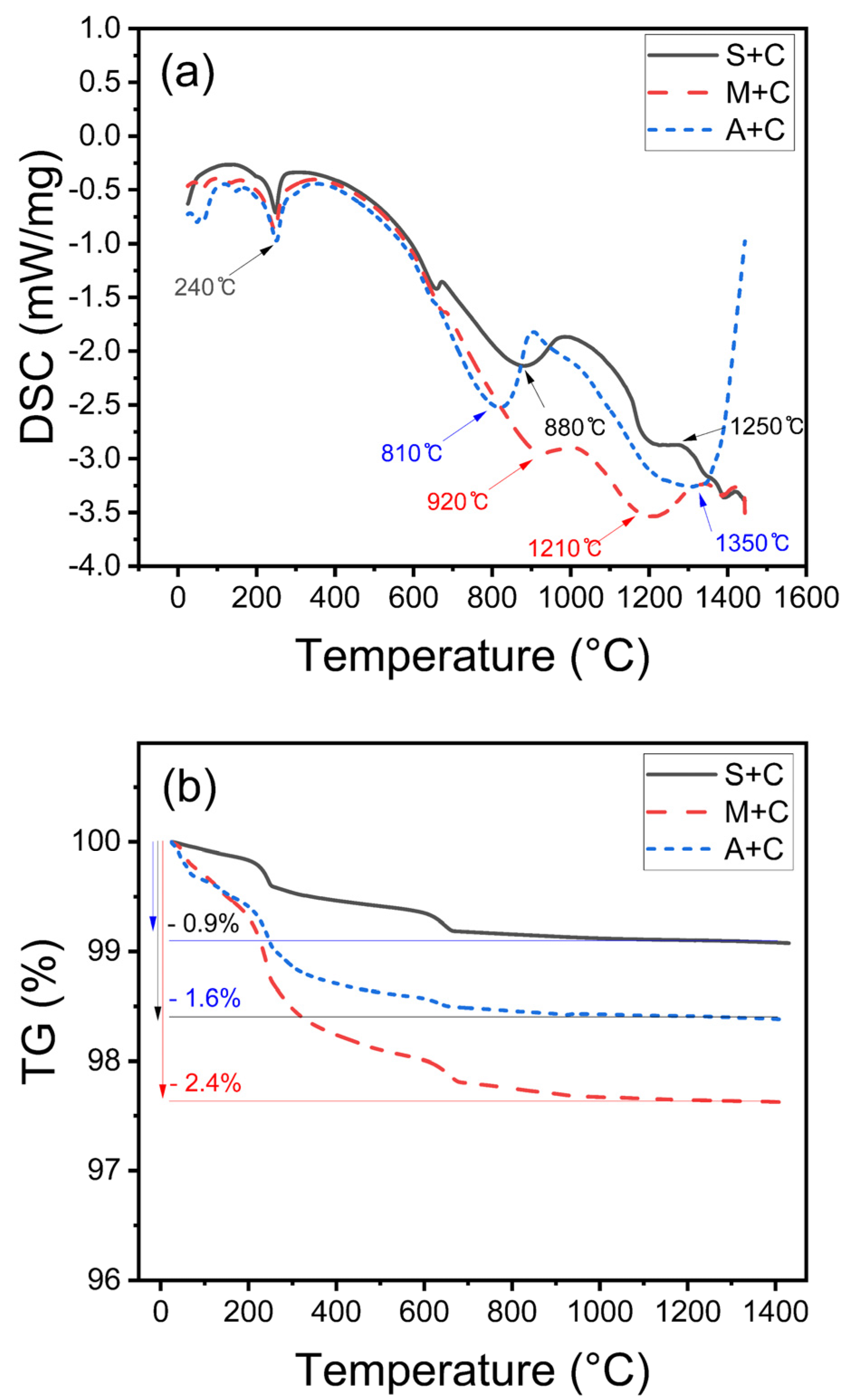
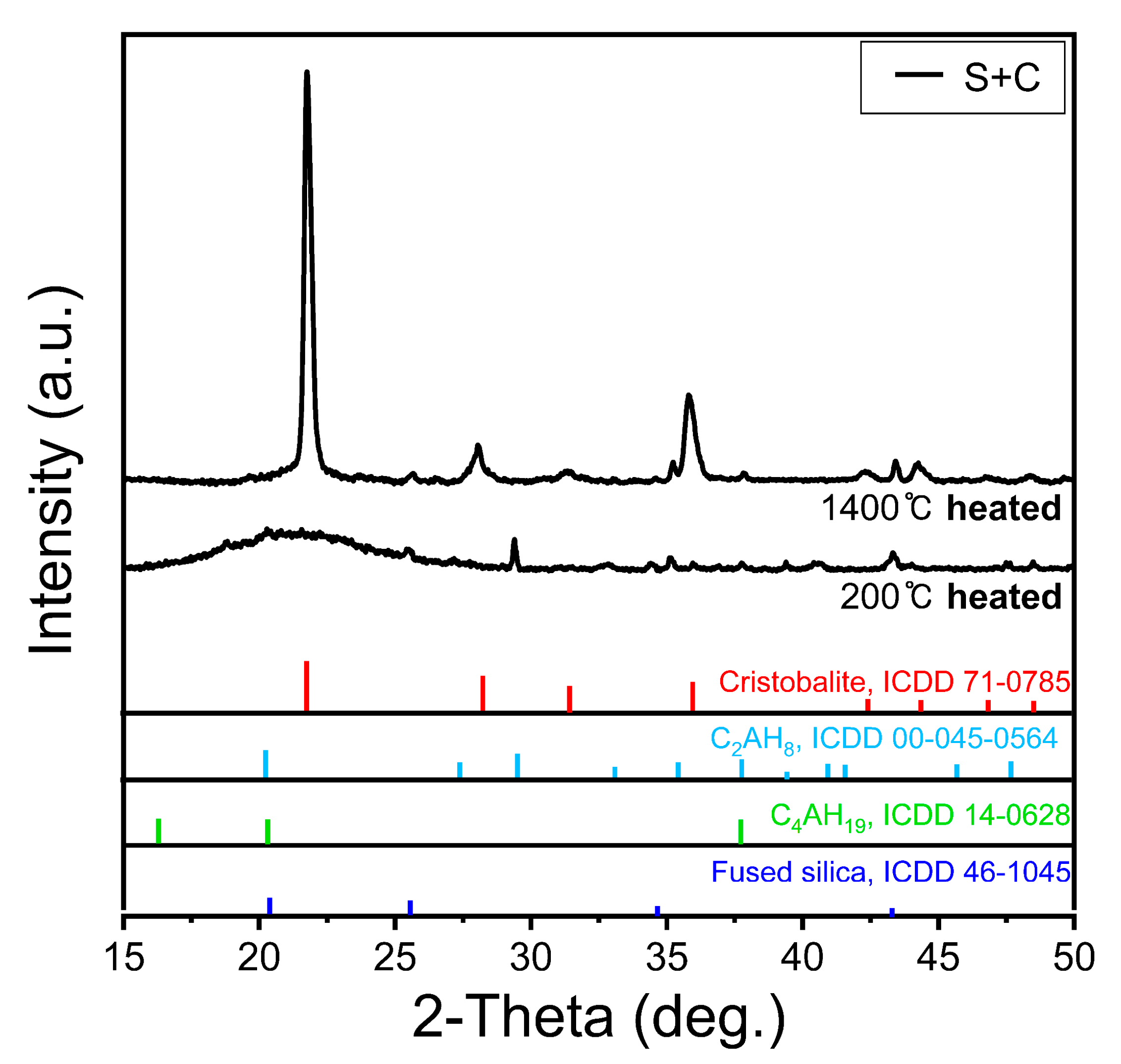
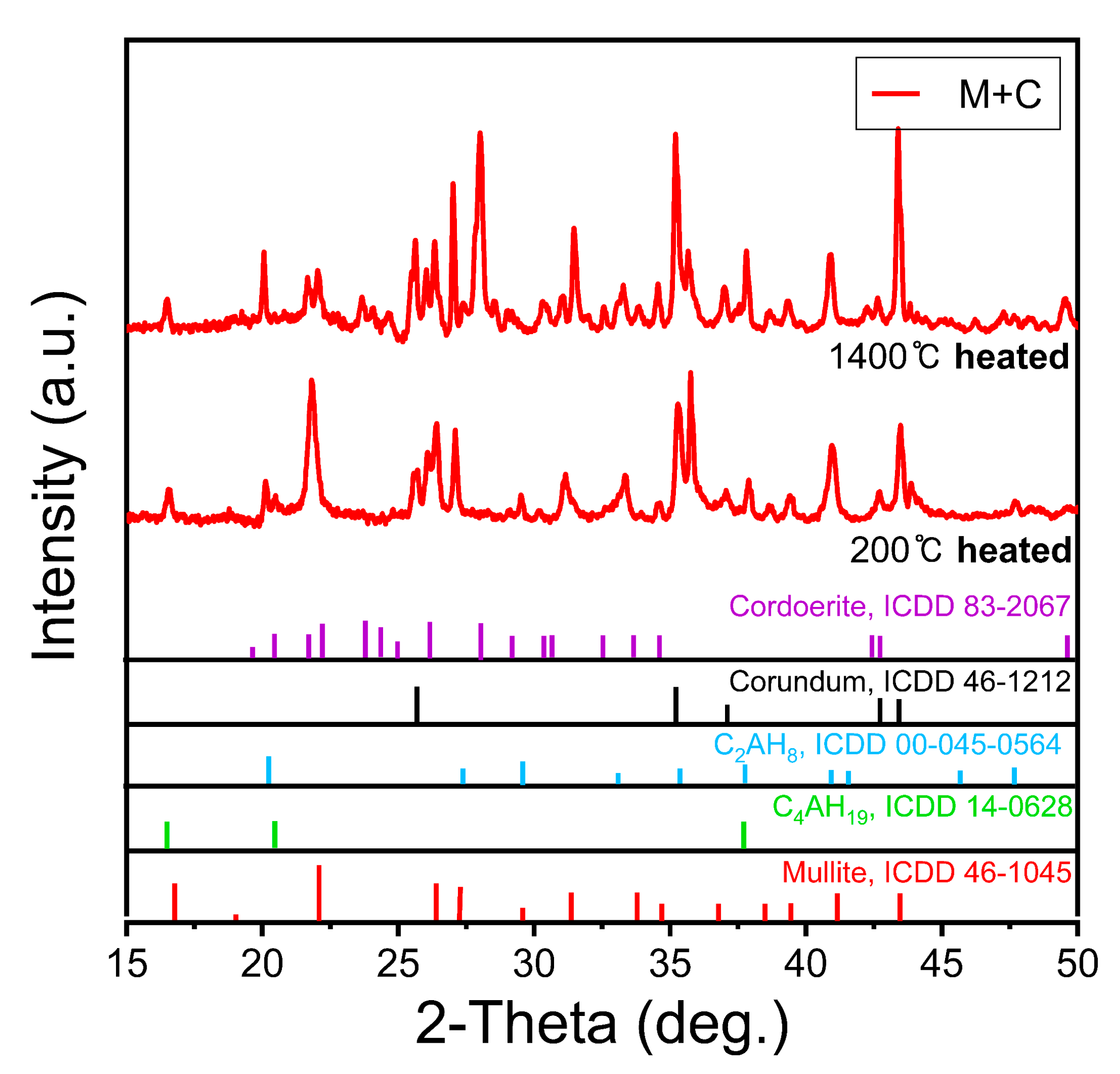
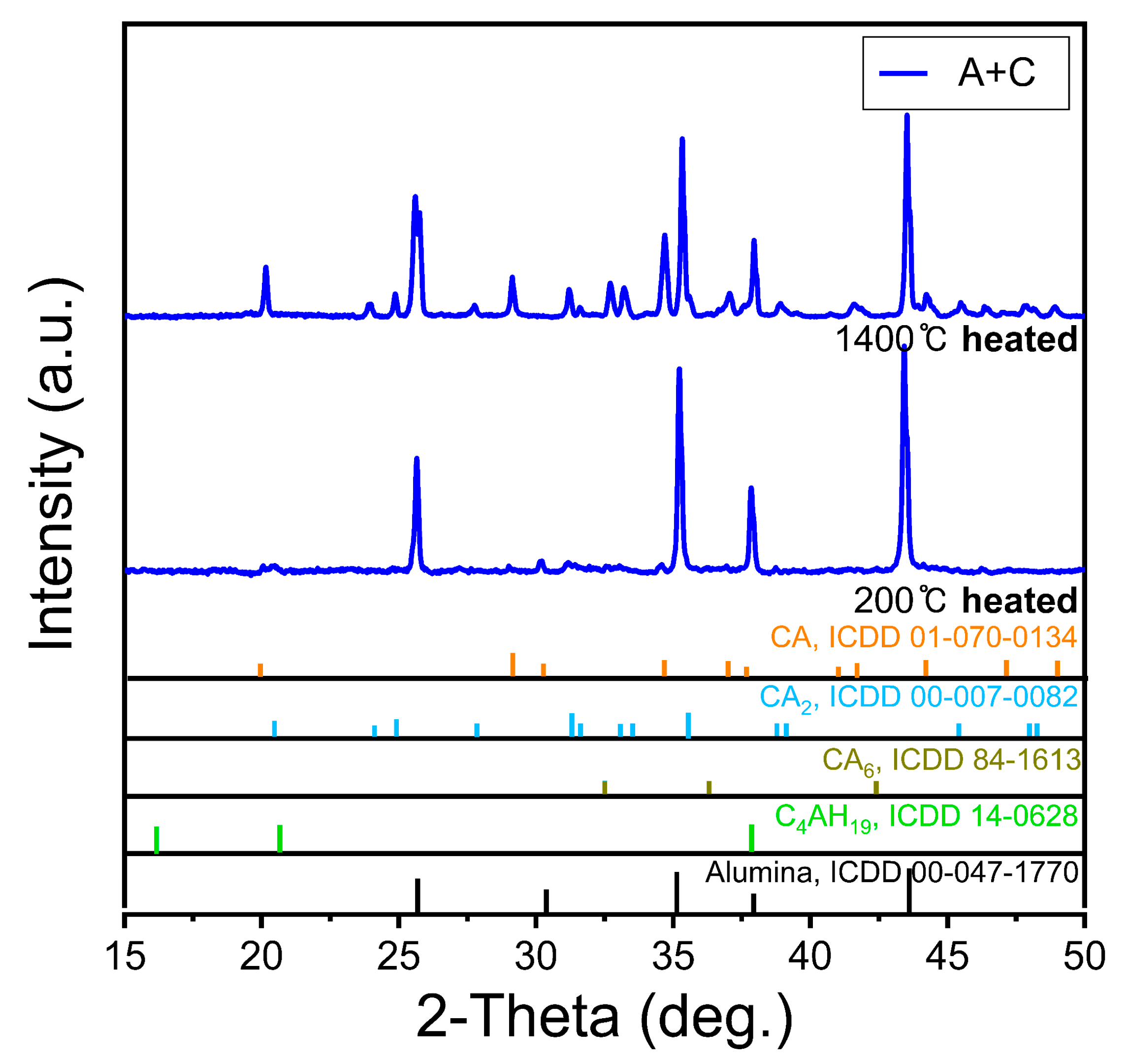
3.3. Thermal Property Evaluation

The initial strength of CAC cement is the formation of hexagonal hydrates (CAH10 and C2AH8) as the main hydration products [27]. However, CAH10 and C2AH8 are metastable and are known to get converted to the more stable C3AH6 and AH3 species. In Figure 5a, every sample shows an AH3 conversion endothermic signal at 240 °C [28,29]. Additionally, all samples exhibit an inflection point with varying strengths near 800 °C. The DSC profile of the S + C sample showed that siliceous sand sintering occurs at approximately 1250 °C, resulting in a strong bond between the sand, but the strength of the actual mold body does not significantly increase. Therefore, the cristobalite formation apparently dominates the crystallization of sand [30,31]. The M + C and S + C samples have similar peaks owing to sintering above 1200 °C [25,32]. However, in the A + C sample, the peak is sintered near 1350 °C [32]. These results support the increase in strength observed at heat treatment above 1000 °C.
Figure 5b compares the reduction in mass according to temperature change. Because the CAC content was different in volume ratio for each prepared sample, the amount of hydration was expected to be different. The CAC content was measured by hydrating the sand, in which 20 wt% was added in mass ratios in the same manner as the S + C, M + C, and A + C samples. Assuming that the rapid gas generation is caused by the molten metal during the casting process, the speed of generation of the initial gas and the amount of generated gas affects the casting defects [27]. The S + C sample exhibits a relatively small mass decrease of 0.9%. In contrast, in the A + C sample, the mass decrease is 1.6% up to 1200 °C, and the M + C sample shows a mass decrease of 2.4%. For the S + C and A + C samples, the mass loss upon heating the mold using molten cast iron is ≤1.6%, the level that is encountered in commercial foundry sand [33]. This reduction in mass is proportional to the amount of gas generated during casting. Therefore, the smaller the generation of gas, the more suitable the mold material is for casting. In addition, the mass reduction velocity can also predict the slowest gas generation process in the case of the S + C sample.
To confirm that the strength trends for each type of sand by high-temperature heat treatment are different, we attempted to identify the phase changes on the surface of molds as the temperature dropped to 1400 °C or less, assuming that the steel was cooled after initial molding for each sample and the temperature of molten metal is approximately 1400 °C. Therefore, the phases after 30 min of heat treatment at 1400 °C were compared.
Figure 6 shows the XRD pattern of the S + C sample. The C2AH8 and C4AH19 phases, which are hydrated by the CAC observed at 200 °C, confirm that the peaks weaken owing to dehydration at 1400 °C. The existing amorphous silica crystallizes at 1400 °C, which promotes the cristobalite phase formation [34,35]. Cristobalite reduces the hardening strength of the mold, thereby affecting the low sintering strength shown in Figure 4b.
Figure 7 shows the XRD pattern of the M + C sample. The molded body dried at 200 °C is sufficiently hydrated and shows no CA, CA2, and CA6 component peaks, which are the CAC phases. The C2AH8 and C2AH19 peaks that appear after the initial hydration disappear or weaken at 1400 °C. The mullite phases, shown at 200 °C, transform to corundum and cordoerite phases when heated to 1400 °C. Then, the formation of corundum appears to affect the reduction in strength of the molded body [26]. However, at 1400 °C, the cordoerite phases are identified more prominently, thus confirming an increase in strength due to the sintering of mullite up to 1400 °C [27].
Figure 8 depicts the XRD pattern of the A + C sample. Similar to the M + C sample, the C2AH8 and C2AH19 peaks that appear after the initial hydration disappear or weaken at 1400 °C. Owing to the compositional characteristics of the initial CAC, no evident crystal phase change is observed as a consequence of the increase in the existing alumina component. However, the CA, CA2, and CA6 components are indeed revived because CAC dehydrates at high temperatures. This seems to be a minor change that does not affect the strength increase caused by the sintering of alumina. In addition, the peaks of C2AH8 and C2AH19 that appear after the initial hydration disappear or weaken at 1400 °C, indicating sufficient dehydration due to high-temperature heat treatment [22,36,37,38].
Every mixed powder sample for 3D printing was investigated by preparing a powder bed using a sessile drop tester (Figure 9a). Figure 9b shows the absorption area of the droplets formed at the powder interface in terms of the spread diameter. In addition, every absorbed region was separated from the powder bed after 4 h to measure the compressive strength. The average spread diameters of the S + C, M + C, and A + C samples are 7.4 mm (narrowest), 9.2 mm, and 8.3 mm, respectively. An inference from the spread diameters of the droplet is that the surface resolution of the molded body is adversely affected when the mold shows high spread diameters [17]. Therefore, the surface quality of the S + C sample is expected to be better. In Figure 9c, the strength values show the same trend as the strength results measured on the molded body, i.e., a lower strength despite the same 4 h curing time. It is only that the formation of forming strength after the hydration process by water drop is lower than the water reactivity by slurrying [5].

4. Conclusions

A fine powder casting usable for powder bed 3D printing, in which CAC was mixed, was manufactured by varying the sand used for sand casting. Droplet absorption time and flowability were optimized at 20% cement volume ratio of CAC cement for each sand. The hydration strength, from which the initial handling strength of the mold can be predicted, was determined to be sufficient within 4 h between 2.5 MPa and 4 MPa, which is the pressure range of commercial inorganic binders. The temperature range for de-powdering was confirmed to be 600–1200 °C by the phase change in each sample, and the defect reduction characteristic of CAC due to the heat applied during the melting process was evident in the S + C sample. The proportion of the gas generated by the thermal reaction was small, which was considered suitable for molding sand (0.9%). The S + C sample formed the best powder interface in terms of spread diameter, as confirmed by the sessile drop tester. In conclusion, the S + C mixed casting sand is highly suitable as a molding material for casting via powder bed 3D printing.

Author Contributions

Conceptualization, S.C.; methodology, G.L., S.K., B.J. and J.S.; validation, H.K. and H.L.; formal analysis, T.K.; investigation, H.K.; resources, H.K. and I.C.; writing—original draft preparation, S.C. and T.K.; writing—review and editing, S.C. and T.K.; visualization, G.L.; supervision, H.L.; project administration, H.K.; funding acquisition, H.K. All authors have read and agreed to the published version of the manuscript.

Funding

This work was supported by Korea Ministry of Trade Industry and Energy (Grant number: #10067386), Korea Ministry of Science and ICT (Grant number: EO200014), and the Ministry of Environment (grant number: 2020003060014).

Institutional Review Board Statement

Not applicable.

Informed Consent Statement

Not applicable.

Data Availability Statement

All data are presented in this article in the form of figures and tables.

Acknowledgments

We acknowledge the financial support from the Ministry of Trade, Industry and Energy, South Korea (MOTIE, grant number: #10067386), the Ministry of Science and ICT, South Korea (MSIT, grant number: EO200014), and the Ministry of Environment (grant number: 2020003060014).

Conflicts of Interest

The authors declare no conflict of interest.

References

  1. Yilmaz, O.; Anctil, A.; Karanfil, T. LCA as a decision support tool for evaluation of best available techniques (BATs) for cleaner production of iron casting. J. Clean. Prod. 2015, 105, 337–347. [Google Scholar] [CrossRef]
  2. Saloum, Q.A.; Abdullah, M.Z.; Hashim, A.A. The preparation of foam cement and determining some of its properties. Eng. Technol. J. 2015, 33, 61–69. [Google Scholar]
  3. Hodder, K.J.; Chalaturnyk, R.J. Bridging additive manufacturing and sand casting: Utilizing foundry sand. Addit. Manuf. 2019, 28, 649–660. [Google Scholar] [CrossRef]
  4. Lowke, D.; Dini, E.; Perrot, A.; Weger, D.; Gehlen, C.; Dillenburger, B. Particle-bed 3D printing in concrete construction—Possibilities and challenges. Cem. Concr. Res. 2018, 112, 50–65. [Google Scholar] [CrossRef]
  5. Pshtiwan, S.; Shami, N.; Gavin, P. An Investigation into the Effects of Deposition Orientation of Material on the Mechanical Behaviours of the Cementitious Powder and Gypsum Powder in Inkjet 3D Printing. In Proceedings of the 36th International Symposium on Automation and Robotics in Construction (ISARC), Banff, AB, Canada, 21–24 May 2019. [Google Scholar]
  6. Gibbons, G.; Williams, R.; Purnell, P.; Farahi, E. 3D Printing of cement composites. Adv. Appl. Ceram. 2010, 109, 287–290. [Google Scholar] [CrossRef] [Green Version]
  7. Huang, S.; Ye, C.; Zhao, H.; Fan, Z. Additive manufacturing of thin alumina ceramic cores using binder-jetting. Addit. Manuf. 2019, 29, 100802. [Google Scholar] [CrossRef]
  8. Zheng, J.; Chen, A.; Zheng, W.; Zhou, X.; Bai, B.; Wu, J.; Ling, W.; Ma, H.; Wang, W. Effectiveness analysis of resources consumption, environmental impact and production efficiency in traditional manufacturing using new technologies: Case from sand casting. Energy Convers. Manag. 2020, 209, 112671. [Google Scholar] [CrossRef]
  9. Anwar, N.; Sappinen, T.; Jalava, K.; Orkas, J. Comparative experimental study of sand and binder for flowability and casting mold quality. Adv. Powder Technol. 2021, 32, 1902–1910. [Google Scholar] [CrossRef]
  10. Upadhyay, M.; Sivarupan, T.; El Mansori, M. 3D printing for rapid sand casting—A review. J. Manuf. Process. 2017, 29, 211–220. [Google Scholar] [CrossRef] [Green Version]
  11. Miyanaji, H.; Rahman, K.M.; Da, M.; Williams, C.B. Effect of fine powder particles on quality of binder jetting parts. Addit. Manuf. 2020, 36, 101587. [Google Scholar] [CrossRef]
  12. Zhang, J.; Amini, N.; Morton, D.A.; Hapgood, K.P. Binder jetting of well-controlled powder agglomerates for breakage studies. Adv. Powder Technol. 2020, 32, 19–29. [Google Scholar] [CrossRef]
  13. Mussatto, A.; Groarke, R.; O’Neill, A.; Obeidi, M.A.; Delaure, Y.; Brabazon, D. Influences of powder morphology and spreading parameters on the powder bed topography uniformity in powder bed fusion metal additive manufacturing. Addit. Manuf. 2020, 38, 101807. [Google Scholar] [CrossRef]
  14. Alexander, A.W.; Chaudhuri, B.; Faqih, A.; Muzzio, F.J.; Davies, C.; Tomassone, M.S. Avalanching flow of cohesive powders. Powder Technol. 2006, 164, 13–21. [Google Scholar] [CrossRef]
  15. Sivarupan, T.; Balasubramani, N.; Saxena, P.; Nagarajan, D.; El Mansori, M.; Salonitis, K.; Jolly, M.; Dargusch, M.S. A review on the progress and challenges of binder jet 3D printing of sand moulds for advanced casting. Addit. Manuf. 2021, 40, 101889. [Google Scholar] [CrossRef]
  16. Simonin, F.; Olagnon, C.; Maximilien, S.; Fantozzi, G.; Diaz, L.A.; Torrecillas, R. Thermomechanical Behavior of High-Alumina Refractory Castables with Synthetic Spinel Additions. J. Am. Ceram. Soc. 2004, 83, 2481–2490. [Google Scholar] [CrossRef]
  17. Lv, X.; Ye, F.; Cheng, L.; Fan, S.; Liu, Y. Binder jetting of ceramics: Powders, binders, printing parameters, equipment, and post-treatment. Ceram. Int. 2019, 45, 12609–12624. [Google Scholar] [CrossRef]
  18. Kang, J.; Shangguan, H.; Deng, C.; Hu, Y.; Yi, J.; Wang, X.; Zhang, X.; Huang, T. Additive manufacturing-driven mold design for castings. Addit. Manuf. 2018, 22, 472–478. [Google Scholar] [CrossRef]
  19. Shakor, P.; Sanjayan, J.; Nazari, A.; Nejadi, S. Modified 3D printed powder to cement-based material and mechanical properties of cement scaffold used in 3D printing. Constr. Build. Mater. 2017, 138, 398–409. [Google Scholar] [CrossRef]
  20. Chun, S.-Y.; Kim, T.; Ye, B.; Jeong, B.; Lee, M.-J.; Lee, D.H.; Kim, E.-S.; Lee, H.; Kim, H.-D. Capillary pressure and saturation of pore-controlled granules for powder bed binder jetting. Appl. Surf. Sci. 2020, 515, 145979. [Google Scholar] [CrossRef]
  21. ExOne GmbH. X1_Handout_Inorganic_Binder. Available online: https://www.exone.com/Admin/ExOne/media/Sand-Binders/210310_X1_Handout_Inorganic_Binder_EN_2021-03_www.pdf (accessed on 10 March 2021).
  22. Black, L.; Breen, C.; Yarwood, J.; Deng, C.-S.; Phipps, J.; Maitland, G. Hydration of tricalcium aluminate (C3A) in the presence and absence of gypsum—studied by Raman spectroscopy and X-ray diffraction. J. Mater. Chem. 2006, 16, 1263–1272. [Google Scholar] [CrossRef]
  23. Sing, S.L.; Yeong, W.Y.; Wiria, F.E. Selective laser melting of titanium alloy with 50 wt% tantalum: Microstructure and mechanical properties. J. Alloys Compd. 2016, 660, 461–470. [Google Scholar] [CrossRef]
  24. Kumar, V.; Singh, V.K.; Srivastava, A.; Kumar, P.H. Mechanochemically synthesized high alumina cement and their implementation as low cement castables with some micro-fine additives. J. Asian Ceram. Soc. 2015, 3, 92–102. [Google Scholar] [CrossRef] [Green Version]
  25. Pratapa, S.; Wahyuni, T.; Fauziyah, N.A.; Apriliyana, G.A.; Mashuri, M.; Firdaus, S. Synthesis and thermomechanical characterization of PEG/cristobalite composites. J. Mech. Sci. Technol. 2017, 31, 3653–3656. [Google Scholar] [CrossRef]
  26. Zhang, S.; Tie, S.; Zhang, F. Cristobalite formation from the thermal treatment of amorphous silica fume recovered from the metallurgical silicon industry. Micro Nano Lett. 2018, 13, 1465–1468. [Google Scholar] [CrossRef]
  27. Saltzberg, M.A.; Bors, S.L.; Bergna, H.; Winchester, S.C. Synthesis of Chemically Stabilized Cristobalite. J. Am. Ceram. Soc. 1992, 75, 89–95. [Google Scholar] [CrossRef]
  28. Mostafa, N.Y.; Zaki, Z.; Elkader, O.H.A. Chemical activation of calcium aluminate cement composites cured at elevated temperature. Cem. Concr. Compos. 2012, 34, 1187–1193. [Google Scholar] [CrossRef]
  29. Wang, F.; Xiangcheng, L.; Li, X.; Zhu, B. Effect of Colloidal Silica on the Hydration Behavior of Calcium Aluminate Cement. Materials 2018, 11, 1849. [Google Scholar] [CrossRef] [Green Version]
  30. Lin, Q.; Zhao, N.; Yao, K.; Jiang, Z.; Tian, B.; Shi, P.; Chen, F. Ordinary Optical Fiber Sensor for Ultra-High Temperature Measurement Based on Infrared Radiation. Sensors 2018, 18, 4071. [Google Scholar] [CrossRef] [PubMed] [Green Version]
  31. Richet, P.; Bottinga, Y.; Denielou, L.; Petitet, J.; Tequi, C. Thermodynamic properties of quartz, cristobalite and amorphous SiO2: Drop calorimetry measurements between 1000 and 1800 K and a review from 0 to 2000 K. Geochim. Cosmochim. Acta 1982, 46, 2639–2658. [Google Scholar] [CrossRef]
  32. Hapgood, K.P.; Litster, J.D.; Biggs, S.; Howes, T. Drop Penetration into Porous Powder Beds. J. Colloid Interface Sci. 2002, 253, 353–366. [Google Scholar] [CrossRef]
  33. Snelling, D.; Williams, C.; Druschitz, A. A comparison of binder burnout and mechanical characteristics of printed and chemically bonded sand molds. In Proceedings of the SFF Symposium, Austin, TX, USA, 4–6 August 2014. [Google Scholar]
  34. Zhang, Z.; Zhou, W.; Han, B.; Li, Y.; Yan, W.; Xu, N.; Li, N.; Wei, J. Preparation and characterization of eco-friendly and low-cost mullite-corundum foamed ceramics with low thermal conductivity. Ceram. Int. 2019, 45, 13203–13209. [Google Scholar] [CrossRef]
  35. Yan, W.; Luo, H.; Tong, J.; Li, N. Effects of sintering temperature on pore characterization and strength of porous cordierite–mullite ceramics by a pore-forming in-situ technique. Int. J. Mater. Res. 2012, 103, 1239–1243. [Google Scholar] [CrossRef]
  36. Wang, Y.; Li, X.; Zhu, B.; Chen, P. Microstructure evolution during the heating process and its effect on the elastic properties of CAC-bonded alumina castables. Ceram. Int. 2016, 42, 11355–11362. [Google Scholar] [CrossRef]
  37. Ukrainczyk, N.; Matusinovic, T.; Kurajica, S.; Zimmermann, B.; Sipusic, J. Dehydration of a layered double hydroxide—C2AH8. Thermochim. Acta 2007, 464, 7–15. [Google Scholar] [CrossRef]
  38. Yum, W.S.; Suh, J.-I.; Kim, D.H.; Oh, J.E. Prevention of potential strength degradation due to conversion of C2AH8 formed in CaO-Ca(HCOO)2-activated GGBFS binder using CaSO4. Constr. Build. Mater. 2020, 253, 119186. [Google Scholar] [CrossRef]
Figure 1. Particle size distribution of component materials.
Applsci 12 00266 g001
Figure 2. Cube molded bodies made from silicone molds.
Applsci 12 00266 g002
Figure 3. (a) Droplet absorption time and (b) avalanche angle by calcium aluminate cement (CAC) content.
Applsci 12 00266 g003
Figure 4. (a) Uniaxial pressing strength by time taken for simple molding, (b) Compressive pressing strength by heat treatment temperature.
Applsci 12 00266 g004
Figure 5. (a) DSC profiles of molded body, (b) TG profiles of molded body.
Applsci 12 00266 g005
Figure 6. XRD peaks after heat treatment at 200 °C and 1400 °C of silica sand and CAC mixed molded body.
Applsci 12 00266 g006
Figure 7. XRD peaks after heat treatment at 200 °C and 1400 °C of mullite sand and CAC mixed molded body.
Applsci 12 00266 g007
Figure 8. XRD peaks after heat treatment at 200 °C and 1400 °C of alumina sand and CAC mixed molded body.
Applsci 12 00266 g008
Figure 9. Powder bed sessile drop test: (a) Proceed with sessile drop test using sessile drop tester, (b) spread diameter as a result of sessile drop test, (c) compressive strength as a result of sessile drop test.
Applsci 12 00266 g009aApplsci 12 00266 g009b
Table 1. Density and particle size distribution data of materials.
ComponentsDensity (g/mL)Particle Size (µm)
D10D50D90
CAC2.11.163.436.06
Silica
sand
0.432.514.477.39
Mullite
sand
1.372.224.347.11
Alumina
sand
1.412.514.477.39
Publisher’s Note: MDPI stays neutral with regard to jurisdictional claims in published maps and institutional affiliations.

