Abstract
Given the possible separation problem caused by the double-span continuous beam bridge under the action of the vertical earthquake, considering the wave effect, the transient wave characteristic function method and the indirect mode superposition method are used to solve the response theory of the bridge structure during the earthquake. Through the example analysis, the pier bending moment changes under different vertical excitation periods and excitation amplitudes are calculated. Calculations prove that: (1) When the seismic excitation period is close to the vertical natural vibration period of the bridge, the main girder and the bridge pier may be separated; (2) When the pier has a high height, the separation has a more significant impact on the longitudinal displacement of the bridge, but the maximum relative displacement caused by the separation is random; (3) Large-scale vertical excitation will increase the number of partitions of the structure, and at the same time increase the vertical collision force between the main girder and the pier, but the effect on the longitudinal displacement of the form is uncertain; (4) When V/H exceeds a specific value, the pier will not only be damaged by bending, but will also be damaged by axial compression.
1. Introduction
As a transportation hub, bridges cause serious damage to the road network when an earthquake occurs, which brings great difficulties to rescue work in the disaster-stricken areas. Simultaneously, this greatly affected the post disaster recovery and reconstruction work and significantly reduced the traffic function between regions [1,2]. In the past, the research on pier failure mainly focused on horizontal excitation, ignoring the influence of vertical earthquake [3,4,5]. However, with the progress of monitoring level in recent years, increasingly monitoring data show that the near-fault earthquake which has a sizeable vertical excitation amplitude, may cause landslides and damage to the bridge foundation [6,7,8,9]. In addition, the pier will suffer more tremendous vertical pressure, or even cause the pier axial compression damage [10,11,12]. Moreover, the fluctuation of axial force may also change the flexural and shear performance of the pier. In this regard, many experimental studies have been carried out [13,14,15,16]. For the main girder, the vertical seismic excitation will also increase the mid-span bending moment and even cause the bending failure of the structure [13,17]. In order to reduce the response of bridges under earthquake, a series of research have been carried out in the field of energy dissipation, such as the performance of rubber-bearing isolators under seismic events [18,19].
For the ratio of vertical and horizontal seismic acceleration, many codes simply set it as 2/3. However, these years, monitoring data show that V/H was far more than 2/3 or even 2. For example, in the Northridge earthquake, the ratio of vertical acceleration to horizontal acceleration reached 1.79, and the amplitude of vertical acceleration reached 1.18 g [20]. Under the Kobe earthquake, the peak acceleration ratio V/H is as high as 2 [21]. Analyzing nine pieces of data collected within 20 km of the Wenchuan earthquake source, the average acceleration ratio V/H is 0.89, and the maximum value is 1.2 [22].
Unlike foreign rigid frame bridges, most bridges in China use rubber bearings. The main beam is directly placed on the pier, and the structure lacks a tensile connection [23,24]. When the vertical seismic excitation is too large, the main beam and pier may be separated. In the 1989 Loms Prieta earthquake [25], a highway bridge is divided under the vertical quake, and the girder is thrown up. When the bridge collides again, the pier directly passes through the bridge deck. Besides, Tanimura [26] considered that the impact force caused by separation might damage the bearing and local pier.
In the past, the collision of bridge mainly focused on the longitudinal beam to beam collision [27], and the research on the vertical collision was less. In addition, the damping measures are set in the horizontal direction [28,29], but the effect of the vertical separation on the horizontal seismic response is ignored. Previous studies on bridge failure assumed that the structure always kept in contact and did not consider the possibility of structural separation caused by the near-fault vertical earthquake. In this study, a double-span continuous beam bridge model is established, and the forced resonance response of the bridge is calculated by using the transient wave function method [30]. The structural displacement response caused by the collision force is calculated by using the indirect modal function method [31]. The force and displacement response of the bridge are calculated by the theoretical approach, and the bending conditions of the bridge pier under different conditions are obtained.
2. Theoretical Model and Vertical Displacement Calculation
The model used in this study is a double-span continuous bridge. The calculation model is shown in Figure 1. The main beam is a prestressed box beam, and the pier is a double-column circular pier. The round lead high damping rubber bearing is used between the main girder and the piers. In the vertical direction, the hysteresis curve of the bearing is long and narrow, ignoring the damping of the vertical bearing. In the horizontal direction, the damping of the bearing is = 20%. In the vertical direction, the stiffness of the bearing is ; in the horizontal direction, the stiffness is . To simplify the calculation, this study makes the following assumptions:
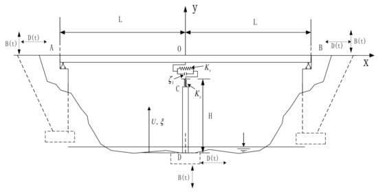
Figure 1.
Model of a double-span continuous beam bridge.
- (1)
- In order to simplify the calculation, linear elastic calculation is adopted for the material of the model, ignoring the nonlinearity of the structure;
- (2)
- Ignore the possible bearing shear failure caused by a horizontal earthquake;
- (3)
- During seismic action, there are often stops in the lateral direction. This study only considers the coupling of vertical and longitudinal seismic activities;
- (4)
- Ignore the difference in the arrival time of the horizontal and vertical seismic waves, assuming that the earthquakes in both directions are excited at the same time.
2.1. Vertical Seismic Response Spectrum
The bridge is located in an area with a seismic intensity of . The reference peak value of horizontal seismic acceleration is selected as 510 gal (5.1). The values of horizontal seismic acceleration under different seismic excitation periods are shown in the specification [32]. The selection of the characteristic value of the vertical seismic response spectrum is given in reference [33], and the epicenter distances are 3 km, 10 km, and 20 km, respectively:
where T is the vertical seismic period, α is the peak value of V/H, and β is the linear attenuation coefficient. When the epicenter distance is 3 km, 10 km, and 20 km, α = 1.5, 1.4, 1.3; β = 5, 4, 3.
Complex seismic waves can be obtained by the superposition of harmonic components of each order by the Fourier expansion method. By calculating the excitation of a single harmonic component, the seismic excitation response of bridge structure in full frequency state can be obtained by superposition method. Therefore, for simplicity, this paper uses the single harmonic motion instead of the seismic excitation, and the acceleration peak value uses the seismic excitation acceleration peak value.
2.2. Theoretical Solution of Displacement Response of Bridge in Vertical Contact Stage
The wave equations of girder AB and pier CD can be described as the following:
In these equations, is the deflection of the beam; is the axial displacement of pier.
The boundary condition of bridge displacement is:
and the displacement continuity condition at the middle of the main girder is:
The continuity condition of shear force and displacement between girder, pier and support are:
Vertical displacement field of the girder can be divided into static displacement , rigid body displacement and dynamic deformation .
Dynamic displacement satisfies the wave equation, continuity condition, equilibrium differential equation, and force boundary condition.
Static displacement of the bridge is as follows:
where is the axial pressure of the initial girder and the support.
The displacement of the rigid body of the bridge is as follows:
The dynamic deformation part of the structure can be expanded as an infinite series of wave mode products:
The equation includes the bending wave function of the girder, the longitudinal wave function of the pier, and the time function .
The wave model function is solved by the characteristic equations. The characteristic equations of the main girder and pier are, respectively:
where (n = 1,2,3,) is the natural frequency of bridge structure, is the coefficient related to the beam flexural wave speed, is the rod phase speed.
Flexural wave modes of the main girder and longitudinal wave of the pier can be described as:
where and are the wave numbers of flexural wave and longitudinal wave respectively. are the coefficients.
The boundary conditions of the characteristic equation are as follows:
The continuity conditions of feature direction are as follows:
The orthogonal consistency of bending wave and longitudinal wave can be obtained by Equation (10):
By introducing Equations (12) and (13) into Equation (11), the wave functions of the bridge structure can be obtained as follows:
By introducing Equation (15) into Equation (13) can solve for and .
Through the orthogonality condition, the time function differential equation of the bridge can be obtained:
By Laplace transformation, can be obtained:
In Equation (7) .
2.3. Corresponding Theoretical Solution of Bridge Vertical Separation Stage Displacement
In the separation process, the beam and the rod do not interact and move at their own characteristic frequencies and .
The displacement response of the main girder and pier can be decomposed into static displacement, rigid displacement, and dynamic deformation, and the main beam does not need to be decomposed into two segments.
The vertical static displacement and rigid displacement of the bridge structure are as follows:
The wave equations of girder AB and pier CD can be described as the following:
The wave mode functions of the main girder and pier are:
where are the coefficients.
The boundary conditions of the characteristic equation are as follows:
The wave functions of the bridge structure can be obtained as follows:
For the main girder and pier, the wavenumber is:
Based on the orthogonality of the wave mode function, the coefficient can be obtained as:
If the separation contact phenomenon occurs many times, it can be assumed that is the time variable of the k-th collision, is the time variable of the k-th separation.
In the k-th separation process, the dynamic displacement responses of the main girder and pier are as follows:
The initial displacement and velocity of the girder and pier structure are considered only by the first mode. By viewing the residual rate and deformation of the last process, the contact separation process is solved continuously.
2.4. Corresponding Theoretical Solution of Bridge Vertical Impact Stage Displacement
When the relative displacement between the girder and pier is less than zero, it is considered that the girder and the pier are in contact again. At the moment of collision contact, the overall frequency of the bridge cannot be calculated. The use of resonance frequency calculation will produce large dispersion, and it is difficult to ensure the convergence of the calculation results. In the process of vertical impact process, the dynamic deformation after contact collision is divided into impact force deformation and dynamic wave deformation . The indirect mode superposition method [24] calculates the structural displacement under the impact force. Initial contact time, += + = 0. In the subsequent vertical collision process, the main beam and the bridge pier have no vertical contact force at the initial moment. And the static displacement of the girder and the pier is zero. It can be concluded that the dynamic displacement of the bridge at the initial moment is:
The collision displacements of the structure are:
where is the generalized collision force. and are the coordinate of the collision point of the main beam and pier, respectively. is the impact force. The positive and negative signs in Equation (27) denote the relationship between force and displacement direction, respectively.
where are modal masses.
In the stage of impact contact, the displacements of the girder and the pier are different. The impact force when the girder and pier are separated, and the collision force . At the impact point, the displacement response is:
By introducing Equation (28) in Equation (29), the vertical load and the collision contact part of bridge structure displacement can be calculated by using the step-by-step integration method.
The partial time function of dynamic deformation is as follows:
The dynamic deformation of the bridge can be expressed as follows:
3. Calculation of Horizontal Displacement Response of Bridge
Referring to the process of solving the vertical displacement response of the bridge, the wave mode equations of the girder and pier in the longitudinal direction can be obtained as:
Refer to Equations (13) and (14) to solve for .
Considering the bearing damping, the time function of the bridge displacement response is:
where .
During the separation process, the wave mode functions of the main beam and bridge pier are:
The time function of the girder and pier is consistent with Equation (28). The calculation process of the longitudinal displacement response of the bridge in the collision process is the same as the vertical calculation process, except that in Equations (27) and (30) is changed to .
By referring to the calculation of longitudinal displacement of bridge under earthquake, the transverse wave function of main girder and pier can be calculated:
During the separation process, the wave mode functions of the main beam and bridge pier are:
The solution of time function is referred to in Section 3.
4. Numerical Simulation and Analysis
The model used in this study is a double-span continuous bridge. The main beam is a prestressed box beam, and the pier is a double-column circular pier. Figure 2 shows the reinforcement details and cross-sectional dimensions of the bridge. The bearing adopts a high damping rubber bearing. To simplify the analysis, the equivalent parameters of the bridge can be calculated according to specifications for the design of highway reinforced concrete and prestressed concrete bridges and culverts in China [24]. According to the specification, the equivalent cross-sectional area of the bridge pier is , the equivalent Young’s modulus of bridge pier is , the equivalent moment of inertia of bridge pier is . The equivalent section area of main girder is , the equivalent Young’s modulus of the main girder is +. The equivalent section moment of inertia of the main girder is . The round lead high damping rubber bearing is used between the main girder and the piers.
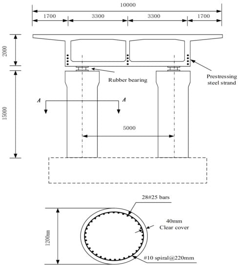
Figure 2.
Dimensions and details of the bridge elevation and section drawings.
In the vertical direction, the hysteresis curve of the bearing is long and narrow, ignoring the damping of the vertical bearing. In the horizontal direction, the damping of the bearing is = 20%. In the vertical direction, the stiffness of the bearing is ; in the horizontal direction, the stiffness is . To simplify the calculation, this study makes the following assumptions:
- (1)
- When the bridge is forced to resonate, the structural force and displacement response are always calculated by elastic deformation;
- (2)
- Ignore the possible bearing shear failure caused by a horizontal earthquake;
- (3)
- During seismic action, there are often stops in the lateral direction. This study only considers the coupling of vertical and longitudinal seismic activities;
- (4)
- Ignore the difference in the arrival time of the horizontal and vertical seismic waves, assuming that the earthquakes in both directions are excited at the same time.
4.1. The Influence of Near-Field Vertical Seismic Acceleration on the Structure
To use the methods in Section 3 and Section 4 to calculate the response of the bridge under earthquake action, it is necessary to select an appropriate number of modes and time-step increments.
Due to the effect of structural damping, the high-order modal response has little effect on the structure. The number of modes selected in this paper is n = 5. The shortest time for the bending wave and axial wave penetration structure of the main beam is = 10.8 × 10⁻³ s. The shortest time for the pier’s bending wave and axial wave to penetrate the system is = 4.38 × 10⁻³ s. Therefore, the chosen time step must be less than 4.38 × 10⁻³ s, and the selected time step in this article is 18 × 10−3 s.
Figure 3 shows the calculation flow chart of the vertical displacement of the bridge in the case of possible vertical separation. The calculation time was 2 s. By recording the time of each separation and recontact in the vertical calculation, and substituting it into the longitudinal seismic calculation, the longitudinal displacement response of the bridge considering the separation condition was obtained.
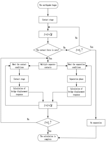
Figure 3.
Flow chart showing bridge vertical displacement calculation procedure.
When the seismic excitation period T = 0.2 s, two types of V/H are selected. One is 0.67 specified in the specification, and the other is given by Equation (1), where the value is 1.0. Figure 4 shows the seismic response of the bridge under two V/H values. When = 0.67, it can be seen that the main girder and the pier are always in contact, and the maximum vertical contact force is 20.4 MN. When = 1, the main girder and the bridge pier will be divided, and the main girder and the bridge pier will be separated six times in 2 s. The vertical contact force increased to 26.6 MN, an increase of 30.4%.
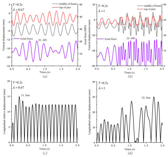
Figure 4.
Seismic response of the bridge under different λ: (a) The vertical displacement and contact force response of the bridge when λ = 0.67; (b) The vertical displacement and contact force response of the bridge when λ = 1; (c) Longitudinal relative displacement of pier beam when λ = 0.67; (d) Longitudinal relative displacement of pier beam when λ = 1.
Compared with the vertical contact force, the separation has a more significant impact on the longitudinal displacement response of the structure. When the height of the pier is H = 15 m (. and are the horizontal and vertical natural vibration periods of the bridge, respectively), the maximum longitudinal relative displacement of the pier and beam is 14.9 mm when the separation is ignored. When the structure is separated, the maximum longitudinal relative displacement increases to 29.9 mm, nearly two times.
Figure 5 shows the effect of separation on the displacement response of the structure when the pier height H = 9 m () and 12 m (). When H = 9 m, the separation caused the maximum longitudinal displacement of the pier beam to increase from 6.06 mm to 7.09 mm, increasing by 17%. When H = 12 m, the separation caused the maximum longitudinal displacement of the pier beam to increase from 17.83 mm to 21.1 mm, increasing 21.9%. The effect of separation on the displacement response of the structure is significantly lower than when the pier height is 15 m. It can be seen that the partition has a more significant impact on the longitudinal displacement of the bridge when .
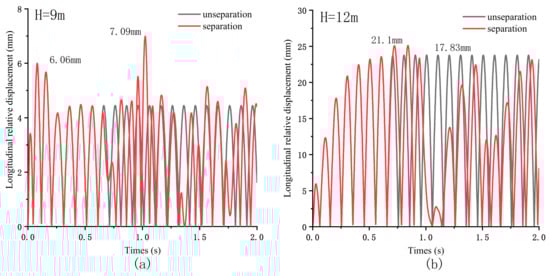
Figure 5.
Longitudinal relative displacement of pier beam under different pier height: (a) Longitudinal relative displacement of pier beam under two conditions of separation or not when H = 9 m; (b) Longitudinal relative displacement of pier beam under two conditions of separation or not when H = 11 m.
Figure 6 shows the change of bending moment of bridge pier in two cases. It can be seen that when the pier is higher, the separation has a greater impact on the bending moment.
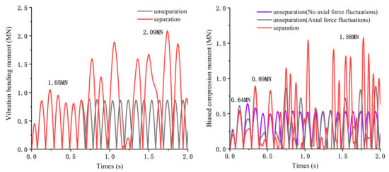
Figure 6.
Bending moment change of bridge pier under two conditions: (left) Vibration bending moment; (right) Eccentric compression moment.
To calculate the bending failure of the pier, it is assumed that the pier is under eccentric compression. The collision diagram is shown in Figure 7. In order to consider the most unfavorable situation of the structure, it is assumed that the leading eccentricity and the maximum collision force occur at the same time. The shear stiffness of the bearing has no attenuation and remains unchanged within the calculation range. The bottom of the pier is composed of three bending moments: the bending moment caused by forced resonance, the bending moment caused by the bearing shear force at the pier bottom, and the bending moment generated by eccentric collision. To simplify the calculation in this study, the influence of the plastic hinge produced at the pier bottom on the displacement of the pier top and the bending moment at the pier bottom is ignored. Ignoring the reset of the bearing during separation, the shear deformation is the longitudinal relative displacement of the pier and beam. The calculation formula of each bending moment is as follows:
where is the magnification factor of the eccentric collision.
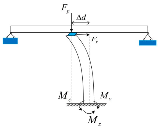
Figure 7.
Force diagram at the bottom of the pier under eccentric compression.
To better study the effect of separation on the structure, three types of piers are selected here: 9 m, 12 m, and 15 m. Figure 8 shows the changes in the bending moment at the bottom of the pier at three heights. Figure 8a shows that when the pier height H = 9 m, the high amplitude vertical acceleration reduces the allowable bending moment of the pier. Whether separated or not, the piers are in a safe zone. When the pier height H = 12 m, is close to the excitation period T. The forced resonance of the bridge pier produces a large bending moment, the high amplitude vertical impact force under the condition of separation reduces the allowable bending moment of the pier and causes damage to the pier. When the pier height H = 15 m, the moment of the pier is 1.66 MN and the structure is in the safe zone. When the system is separated, the bending moment increases to 2.94 MN, which increases by 77%, and the pier is damaged.
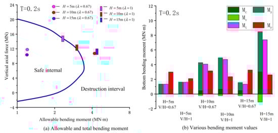
Figure 8.
Various bending moments and allowable bending moments at the pier bottom: (a) Changes of various bending moments at the bottom of the pier at three different heights; (b) Longitudinal relative displacement of pier beam under different pier height.
Figure 8b shows the variation of various bending moments at the pier bottom under different conditions. It can be seen that the shear stiffness of rubber bearing is low, and the bending moment produced by bearing shear has little influence on pier failure in most cases. When H = 12 m, the pier failure is mainly due to forced resonance, and the bending moment caused by eccentric compression is significantly increased compared with H = 9 m. When H = 15 m, the seismic excitation period is far away from the longitudinal natural vibration period of the bridge, the seismic response of the bridge is low, and the structure is always in the safe range. When the structure is separated, and are immensely increased by the large expansion of longitudinal relative displacement. It can be seen that ignoring the bridge separation caused by high vertical acceleration not only underestimates the vertical contact force between the main girder and pier, but also may misestimate the seismic displacement response of the bridge.
4.2. Seismic Response of Bridge Pier under Different Excitation Periods
The seismic excitation period affects the bridge displacement response. The research range selected in Figure 9 is T = 0.05 s0.5 s. The change of seismic acceleration under a long period, the characteristic site period = 0.3 s, is selected in this study. It can be seen that only when the excitation period is close to the vertical first-order natural vibration period of the bridge that the structure will separate, and the higher-order modes have little effect on the structural separation. The full longitudinal relative displacement of the pier beam will peak at , but this crest may not be the maximum value. When the pier height H = 15 m, the ultimate value appears at T = 0.25 s, and the excitation period at this time is close to and far away from . It can be seen that the most unfavorable conditions caused by the forced vibration of the bridge piers are not entirely in the interval . When the piers are higher (), the structural separation produced in the interval will increase the seismic response of the bridge and cause the pier to be bent damaged.
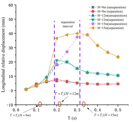
Figure 9.
Longitudinal relative displacement of pier beam under different excitation periods.
The bending failure of the pier is affected by the relative displacement of the pier and beam. The change of axial force not only affects the allowable bending moment, but also changes the bending moment generated by eccentric compression. Figure 10 shows the vertical contact force between the main girder and the pier under different excitation cycles. It can be seen that the peak value of the vertical contact force is concentrated in the interval. Compared with the specification = 0.67, calculated by Equation (1), it has a more considerable peak value in a short period and a smaller peak value in an extended period. The structure separation of the bridge will occur under both conditions, but the excitation period of the structural separation calculated by Equation (1) is shorter. The maximum vertical contact force of the two is the same, in the range of 2.5 3.
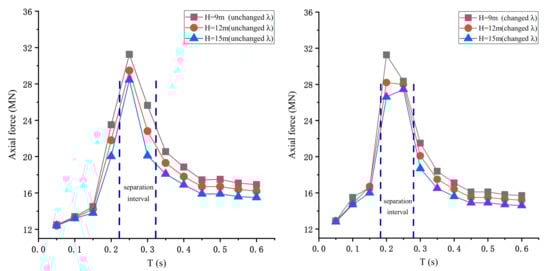
Figure 10.
Various bending moments and allowable bending moments at the pier bottom: (left) Changes of various bending moments at the bottom of the pier at three extra heights; (right) Longitudinal relative displacement of pier beam under extra pier height.
Figure 11 shows the variation of the bending moment of the pier under different seismic excitation periods. Under different excitation periods, when H = 9 m, the bending moment produced by eccentric compression is shallow, which can be ignored. When H = 12 m, has a peak at T close to , which is due to the more enormous displacement response produced by resonance. When H = 15 m, has two extremes, one is when T is close to , this is because the resonance produces a larger displacement response. One is in the separation interval, which is due to the expansion of the relative displacement due to structural separation. It can be seen from Figure 11b,c that the variation trend of and in different seismic periods is the same as that of . When the height of the pier is low, the bending moment of the pier under the earthquake action is small. When the pier height is higher, the bending moment at the bottom of the pier is greater. In addition, when considering the structure separation, there will be two wave peaks, which need to consider the pier damage in two cases.
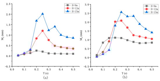
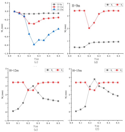
Figure 11.
Various bending moments at the bottom of the pier under different periods: (a) Bending moment caused by eccentric collision under different excitation periods; (b) Bending moment generated by forced vibration under different excitation periods; (c) Bending moment caused by bearing shear under different excitation periods; (d) When H = 9 m full moment and the permissible moment pier; (e) When H = 12 m full moment and the permissible moment pier; (f) When H = 15 m full moment and the permissible moment pier.
The variation trend of the allowable bending moment of the pier with three heights under different excitation periods is the same. Only when T approaches to , there is an extreme value, and the other intervals remain unchanged. With the increase of pier height, the vertical contact force decreases and the allowable bending moment increases. When H = 9 m, the total bending moment of the pier has little change. When H = 12 m and 15 m, the total bending moment of the pier increases greatly, the former is caused by resonance, and the latter is caused by structural separation. With the increase of excitation period, the total bending moment decreases gradually when H = 12 m. However, when H = 15 m, the second wave crest will appear, and the total bending moment is close to the allowable bending moment, which may cause damage to the pier.
4.3. Seismic Response of Bridge Piers under Different Vertical Excitation Amplitudes
A large number of monitoring data show that the vertical and horizontal acceleration amplitudes of near-field earthquakes are not only more than 2/3 of the code, but sometimes even more than one or even close to two. To study the influence of vertical seismic excitation amplitude on pier failure, Figure 12a shows the variation of longitudinal relative displacement and vertical contact force of pier beam with vertical seismic excitation amplitude when the length of the single-span beam is L = 38m and the pier height is H = 9 m, 12 m and 15 m, respectively. When H = 9 m and 12 m, the amplitude of V/H has little effect on the longitudinal displacement of pier beam. When H = 15 m, the maximum longitudinal relative displacement of pier beam is irregular, which is because the displacement response of the structure after separation is related to the initial position and velocity at the time of separation, and has great randomness. Compared with the longitudinal displacement, V/H has a greater impact on the vertical impact force. It can be seen from Figure 12b that with the increase of V/H, the vertical contact force of the structure increases monotonically, and the smaller the pier height, the greater the increase. When V/H exceeds a certain value, the vertical impact force exceeds the compressive strength of the pier, resulting in compression failure of the pier.
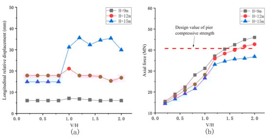
Figure 12.
Seismic response of bridges under different vertical seismic excitation amplitudes: (a) Longitudinal relative displacement of main girder and pier under different vertical seismic excitation amplitudes; (b) Vertical contact force between main girder and pier under different vertical seismic excitation amplitudes.
Figure 13 shows the bending moment variation of pier under different vertical excitation amplitudes. As the amplitude of V/H increases, the total bending moment of the bridge pier shows an increasing trend. When H = 15 m, the total bending moment will increase drastically and fluctuate after the structure is separated. The allowable bending moment of the bridge pier decreases monotonously as the vertical collision force increases. It can be seen from Figure 13 that when the height of the pier is low, with the increase of V/H, the damage of the pier is mainly due to the increase in the vertical collision force, which reduces the allowable bending moment of the pier. When the height of the pier is high, the damage is partly due to the decrease in the allowable bending moment, and partly due to the increase in the total bending moment of the pier.
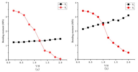
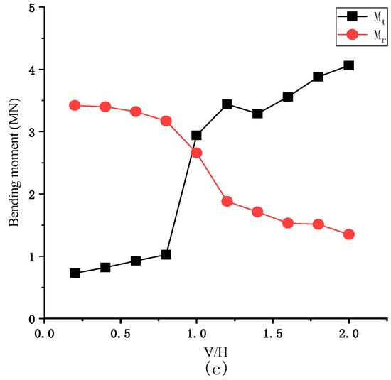
Figure 13.
Bending moments at the bottom of the pier under different periods: (a) When H = 9 m total moment and the permissible moment pier; (b) When H = 12 m total moment and the permissible moment pier; (c) When H = 15 m total moment and the permissible moment pier.
5. Discussion
In this paper, the influence of the separation of main girder and pier on the failure of bridge pier under near-field earthquake is calculated by numerical simulation. The seismic force and displacement responses of medium- and small-span bridges under the condition of separation can be easily calculated by using this method. However, in order to simplify the calculation, the structure is assumed to be always in the elastic stage, and the plastic hinge at the bottom of the pier is ignored, resulting in a certain error. Therefore, the influence of the plastic hinge at the bottom of the pier needs to be considered in the follow-up, and further verification is obtained through finite element calculation.
6. Conclusions
In this study, the influence of near-fault vertical seismic excitation amplitude on pier failure was considered. Double-span continuous beam bridge model was established. The transient wave function expansion method and the indirect mode superposition method were used. The theory solved the longitudinal displacement and vertical contact force response of the bridge. By applying different vertical excitation amplitudes, the damage of three types of piers under different amplitudes was studied. The following conclusions were obtained by calculation:
- For medium- and small-span rubber bearing bridges, when the designed piers were high ( > ), the change of longitudinal displacement caused by separation will affect the bending failure of bridge piers.
- Only when the excitation period was close to the vertical natural vibration period can the structure separation occur, and the allowable moment of pier is the lowest. There may be two peaks in the total bending moment of pier. The excitation period was close to the longitudinal natural vibration period, and the other is when the structure is separated.
- With the increase of V/H, the total bending moment at the bottom of pier increased slowly, the allowable bending moment decreased gradually, and the pier is damaged.
- When V/H exceeded a specific range, the structure will be separated and a large vertical impact force will be produced. The impact force will cause the pier axial compression failure.
Author Contributions
Conceptualization, W.A. and G.S.; methodology, W.A.; software, W.A.; validation, W.A. and G.S.; formal analysis, W.A. and G.S.; investigation, W.A.; resources, W.A.; data curation, G.S.; writing—original draft preparation, W.A.; writing—review and editing, W.A.; visualization, W.A.; supervision, G.S.; project administration, G.S.; funding acquisition, G.S. All authors have read and agreed to the published version of the manuscript.
Funding
APC was funded by Science and Technology Project of Jiangxi Provincial Education Department (GJJ202908).
Institutional Review Board Statement
Not applicable.
Informed Consent Statement
Informed consent was obtained from all subjects involved in the study.
Conflicts of Interest
The authors declare no conflict of interest.
Nomenclature
| the magnitude of V/H | |
| α | the peak value of V/H |
| β | the linear attenuation coefficient |
| density of structure | |
| modulus of elasticity of main girder | |
| main girder section coefficient | |
| main girder section area | |
| modulus of elasticity of pier | |
| pier section coefficient | |
| pier section area | |
| q | uniform load of main beam |
| the deflection of the beam (i = 1,2) | |
| static displacement of the beam (i = 1,2) | |
| dynamic deformation part of the beam | |
| the deflection of the pier (i = 1,2) | |
| static displacement of the pier (i = 1,2) | |
| dynamic deformation part of the pier | |
| axial pressure of the initial girder and the support | |
| equation includes the bending wave function of the girder at contact time (i = 1,2) | |
| the longitudinal wave functionof the pier at contact time | |
| equation includes the bending wave function of the girder at separation of time (i = 1,2) | |
| the longitudinal wave functionof the pier at separation of time | |
| natural vibration frequency of the structure at contact time | |
| main beam seismic frequency at contact time | |
| pier seismic frequency at contact time | |
| natural frequency of the vibration considering the damping effect | |
| bearing damping | |
| structural self-damping | |
| wave numbers of flexural wave at contact time (longitudinal direction is wave numbers of longitudinal wave) | |
| wave numbers of longitudinal wave at contact time (longitudinal direction is wave numbers of flexural wave) | |
| wave numbers of flexural wave at separation time (longitudinal direction is wave numbers of longitudinal wave) | |
| wave numbers of longitudinal wave at separation time (longitudinal direction is wave numbers of flexural wave) | |
| time function of the bridge | |
| time function of the main beam | |
| time function of the pier | |
| impulse response function of the main beam | |
| impulse response function of the pier | |
| modal masses of the main beam | |
| modal masses of the pier |
References
- Li, H.N.; Xiao, S.Y.; Huo, L.S. Damage investigation and analysis of Engineering structures in the Wenchuan earthquake. J. Build. Struct. 2008, 29, 10–19. [Google Scholar]
- Zhuang, W.L.; Liu, Z.; Jiang, J. Earthquake-induced damage analysis of highway bridges in Wenchuan earthquake and countermeasures. Chin. J. Rock Mech. Eng. 2009, 28, 1377–1387. [Google Scholar]
- Xu, S.Y.; Zhang, J. Axial–shear–flexure interaction hysteretic model for RC columns under combined actions. Eng. Struct. 2012, 34, 548–563. [Google Scholar] [CrossRef]
- Ghannoum, W.M.; Mohle, J.P. Rotation-Based Shear Failure Model for Lightly Confined RC Columns. J. Struct. Eng. 2012, 138, 1267–1278. [Google Scholar] [CrossRef]
- Elwood, K.J. Modeling failures in existing reinforced concrete. Can. J. Civ. Eng. 2004, 31, 846–859. [Google Scholar] [CrossRef]
- Button, M.R.; Cronin, C.J.; Mayes, R.L. Effect of Vertical Motions on Seismic Response of Highway Bridges. J. Struct. Eng. 2002, 128, 1551–1564. [Google Scholar] [CrossRef]
- Huang, F.; Cao, Z.; Jiang, S.H.; Zhou, C.; Huang, J.; Guo, Z. Landslide susceptibility prediction based on a semi-supervised multiple-layer perceptron model. Landslides 2020, 17, 2919–2930. [Google Scholar] [CrossRef]
- Li, W.; Fan, X.; Huang, F.; Chen, W.; Hong, H.; Huang, J.; Guo, Z. Uncertainties analysis of collapse susceptibility prediction based on remote sensing and GIS: Influences of different data-based models and connections between collapses and environmental factors. Remote Sens. 2020, 12, 4134. [Google Scholar] [CrossRef]
- Zhu, L.; Huang, L.; Fan, L.; Huang, J.; Huang, F.; Chen, J.; Zhang, Z.; Wang, Y. Landslide Susceptibility Prediction Modeling Based on Remote Sensing and a Novel Deep Learning Algorithm of a Cascade-Parallel Recurrent Neural Network. Sensors 2020, 20, 1576. [Google Scholar] [CrossRef]
- Wilson, T.; Chen, S.; Mahmoud, H. Analytical case study on the seismic performance of a curved and skewed reinforced concrete bridge under vertical ground motion. Eng. Struct. 2015, 100, 128–136. [Google Scholar] [CrossRef]
- Kunnath, S.K.; Erduran, E.; Chai, Y.H.; Yashinsky, M. Effect of near-fault vertical ground motions on seismic response of high overcrossings. J. Bridge Eng. 2008, 13, 282–290. [Google Scholar] [CrossRef]
- Yu, C.P. Effect of Vertical Earthquake Components on Bridge Response. Ph.D. Thesis, University of Texas, Austin, TX, USA, 1998. [Google Scholar]
- Papazoglou, A.J.; Elnashai, A.S. Analytical and field evidence of the damaging effect of vertical earthquake ground motion. Earthq. Eng. Struct. Dyn. 1996, 25, 1109–1137. [Google Scholar] [CrossRef]
- Varecac, D.; Draganic, H.; Gazic, G. Influence of the Vertical Component of Earthquake on Large Span Rc Beams. Teh. Vjesn. Tech. Gaz. 2010, 17, 357–366. [Google Scholar]
- Kim, S.J.; Holub, C.J.; Elnashai, A.S. Experimental investigation of the behavior of RC bridge piers subjected to horizontal and vertical earthquake motion. Eng. Struct. 2011, 33, 2221–2235. [Google Scholar] [CrossRef]
- Güllü, H.; Jaf, H.S. Full 3D nonlinear time history analysis of dynamic soil structure interaction for a historical masonry arch bridge. Environ. Earth Sci. 2016, 75, 1–17. [Google Scholar] [CrossRef]
- Zheng, W.; Leonardo, D.O.; Jamie, E.P. Seismic response of a bridge-soil-foundation system under the combined effect of vertical and horizontal ground motions. Earthq. Eng. Struct. Dyn. 2012, 4, 545–564. [Google Scholar]
- Rezaei Rad, A.; Banazadeh, M. Probabilistic Risk-Based Performance Evaluation of Seismically Base-Isolated Steel Structures Subjected to Far-Field Earthquakes. Buildings 2018, 8, 128. [Google Scholar] [CrossRef]
- Sharma, A.; Jangid, R.S. Seismic Response of Base-Isolated Benchmark Building with Variable Sliding Isolators. J. Earthq. Eng. 2010, 14, 1063–1091. [Google Scholar] [CrossRef]
- Bozorgnia, Y.; Niazi, M.; Campbell, K.W. Characteristic of free-field vertical ground motion during the Northridge earthquake. Earthq. Spectra 1995, 11, 515–526. [Google Scholar] [CrossRef]
- Wang, G.-Q.; Zhou, X.-Y.; Zhang, P.-Z.; Igel, H. Characteristics of amplitude and duration for near fault strong ground motion from the 1999 Chi-Chi, Taiwan earthquake. Soil Dyn. Earthq. Eng. 2002, 22, 73–96. [Google Scholar] [CrossRef]
- Wang, D.; Xie, L. Attenuation of peak ground accelerations from the great Wenchuan earthquake. Earthq. Eng. Eng. Vib. 2009, 8, 179–188. [Google Scholar] [CrossRef]
- Wang, C.J.; Shih, M.H. Performance study of a bridge involving sliding decks and pounded abutment during a violent earthquake. Eng. Struct. 2007, 29, 802–812. [Google Scholar] [CrossRef]
- Zuo, Y.; Sun, G.J.; Li, H.J. Comparison and Research of Unseating Prevention Measures in Seismic Codes of China and Foreign Countries. J. Disaster Prev. Mitig. Eng. 2016, 36, 617–623, 639. [Google Scholar]
- Han, W.; Song, C.; Li, Q. Strong ground motion at meizoseisal area & safety of important engineering projects at potential earthquake region. J. Eng. Geol. 2004, 12, 346–353. [Google Scholar]
- Tanimura, S.; Mimura, K.; Nonaka, T.; Zhu, W. Dynamic failure of structures due to the great Hanshin-Awaji earthquake. Int. J. Impact Eng. 2000, 24, 583–596. [Google Scholar] [CrossRef]
- Kim, S.H.; Shinozuka, M. Effects of Seismically Induced Pounding at Expansion Joints of Concrete Bridges. J. Eng. Mech. 2003, 129, 1225–1234. [Google Scholar] [CrossRef]
- Li, S.; Guo, A.; Cui, L. Pounding-induced stress wave analysis and mitigation of highway bridges under earthquake. In Proceedings of the 11th International Conference in Experimental Structural Engineering, University of Illinois Urbana-Champaign, Chmapaign, IL, USA, 1–2 August 2015. [Google Scholar]
- DesRoches, R.; Delemont, M. Seismic retrofit of simply supported bridges using shape memory alloys. Eng. Struct. 2002, 24, 325–332. [Google Scholar] [CrossRef]
- Yang, H.B.; Yin, X.C.; Hao, H. Theoretical Investigation of Bridge Seismic Responses with Pounding under Near-Fault Vertical Ground Motions. Adv. Struct. Eng. 2015, 18, 452–468. [Google Scholar] [CrossRef]
- Yang, H.B.; Yin, X.C. Transient responses of girder bridges with vertical poundings under near-fault vertical earthquake. Earthq. Eng. Struct. Dyn. 2015, 44, 2637–2657. [Google Scholar] [CrossRef]
- Xing, Y.F.; Wang, L.J. Analysis of wave propagation in the built-up structures of rod-beam and beam-beam. J. Beijing Univ. Aeronaut. Astronaut. 2013, 30, 520–523. [Google Scholar]
- Ministry of Housing and Urban-Rural Development of the People’s Republic of China. CJJ 166-2011. Code for Seismic Design of Urban Bridges; Ministry of Housing and Urban-Rural Development of the People’s Republic of China: Beijing, China, 2011. [Google Scholar]
Publisher’s Note: MDPI stays neutral with regard to jurisdictional claims in published maps and institutional affiliations. |
© 2021 by the authors. Licensee MDPI, Basel, Switzerland. This article is an open access article distributed under the terms and conditions of the Creative Commons Attribution (CC BY) license (https://creativecommons.org/licenses/by/4.0/).