1. Introduction
A dental prosthesis is an artificial substitute, which has the role of reestablishing the dental arch interrupted by edentation and restoring the functions of the dento-maxillary system. Furthermore, it is a biological infrastructure with the role of support and aggregation for prosthetic construction. Therefore, when analyzing the longevity of a prosthetic appliance, we must follow the two structural elements equally, which respond differently to demands and have different behaviors over time [
1].
The treatment solutions for a single-tooth edentation are multiple and can be chosen according to several criteria: esthetics, mechanical resistance, the degree of teeth damage and, last, but not least, the patients’ wishes. Possible treatment options in this situation can be metal–ceramic, all-ceramic, direct or indirect fiber-reinforced composite fixed dental prostheses, minimally invasive dental bridges or implants [
2].
Posterior fixed partial dentures have different biomechanical behavior according to the restorative materials used. For example, some authors report that acrylic resin fixed prosthetic restorations can lessen the stress level in the connector region, and resin composite dental bridges can diminish the magnitude of stress on the layer of cement [
3].
Inlay-retained fixed dental prostheses may indicate when adjacent teeth have been previously restored and when implant placement is not possible or not indicated. Inlay-retained bridges are also a good option in patients with good oral hygiene and low susceptibility to caries, with a minimum coronal tooth height of 5 mm, parallel abutments, and a maximum mesiodistal edentulous space of 12 mm. Contraindications include severe dental malpositions, the absence of enamel on the preparation margins, extensive crown defects and mobility of abutment-teeth [
4,
5].
A particularly important aspect that influences the clinical longevity of the minimally invasive bridges is mechanical resistance. This parameter depends on the dental materials used, design, and developing tensions, both at the bridge elements and at the abutment teeth [
6].
Finite element analysis is a method that has as a main objective the modeling and description of mechanical behavior of elements with complex geometry, with the added advantage of the simplicity of basic concepts; the mathematical model thus realized includes certain working hypotheses, simplifications and generalizations [
7]. To evaluate the stability of dental bridges and the stress they exert on the abutment teeth under conditions of variable masticatory demands, a working hypothesis can be simulated in the situation of a reduced partial edentation.
Inlay retained bridges are highly appreciated in the prosthodontic clinical practice since they are minimally invasive for the biological support tissues. However, from a biomechanical perspective, it is not clear whether they are as reliable as other therapeutic options [
5,
6]. Moreover, it is not clear whether the stress determined by the loading force can cause damage to the prosthetic device or to the abutment teeth, thus influencing the longevity of this restoration.
Because testing biomechanical parameters is not possible in the oral cavity without affecting the integrity of hard and soft tissues, the finite element method (FEM) is a useful way to appreciate the strengths and weaknesses of a prosthetic device and the stress induced into the dental support in various circumstances [
8].
Considering all this and the multitude of design possibilities of the prosthetic appliance and possible materials available for the restoration, further studies are needed to clarify the indications and limitations of fixed dental bridges to maximize treatment outcome.
The present study aims to analyze stress levels at a three-element dental bridge, with inlays used as retainers to evaluate tension levels on abutment teeth and analyze the maximum tensions applied to abutment teeth and the dental prosthesis, considering the dynamic action of masticatory forces.
For this purpose, we used finite element analysis, a method that provides an image of the distribution of forces, both at the artificial substitute and the biological support level [
9].
2. Materials and Methods
The finite element method attempts to approximate a solution to a problem by admitting that the domain is divided into subdomains or finite elements, with simple geometric shapes and the function of an unknown state variable that is defined around each element. The operation of choosing the number and type of finite elements, corroborated with the division of the domain into several finite elements, is called discretization. When preparing the analysis model, one must take into account that the shape and dimensions of the design influence the accuracy and time of analysis; in this sense, for a given problem, there are several variants of analysis models.
Description of the geometric model and finite element modeling was first performed, a stage that includes: modeling of material characteristics, choosing the finite elements and introducing properties, generating the finite element structure, introduction of limit conditions and forces. Analysis and solution of the finite element model involved setting the solving parameters and then visualizing the states and variations of the parameters.
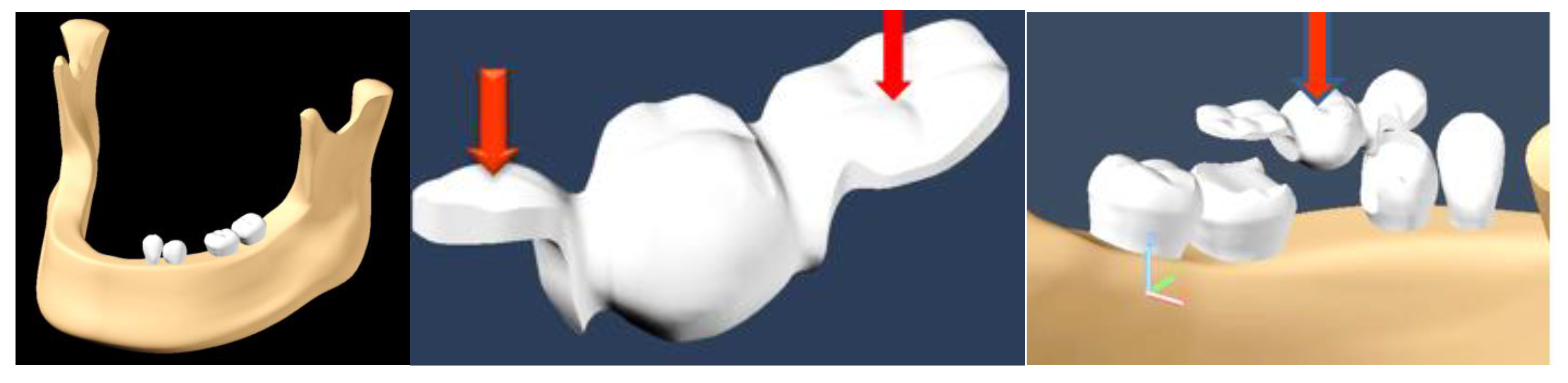
Images of molars, canines, premolars and incisors were taken as a reference; their dimensions were made on a scale, according to the dimensions of the molars on computed tomography (CT) images. Based on the mandibular model, the absence of tooth 3.5 was simulated. To simplify the finite element analysis, only the dental elements 3.3, 3.4, 3.6 and 3.7 were preserved from the assembly.
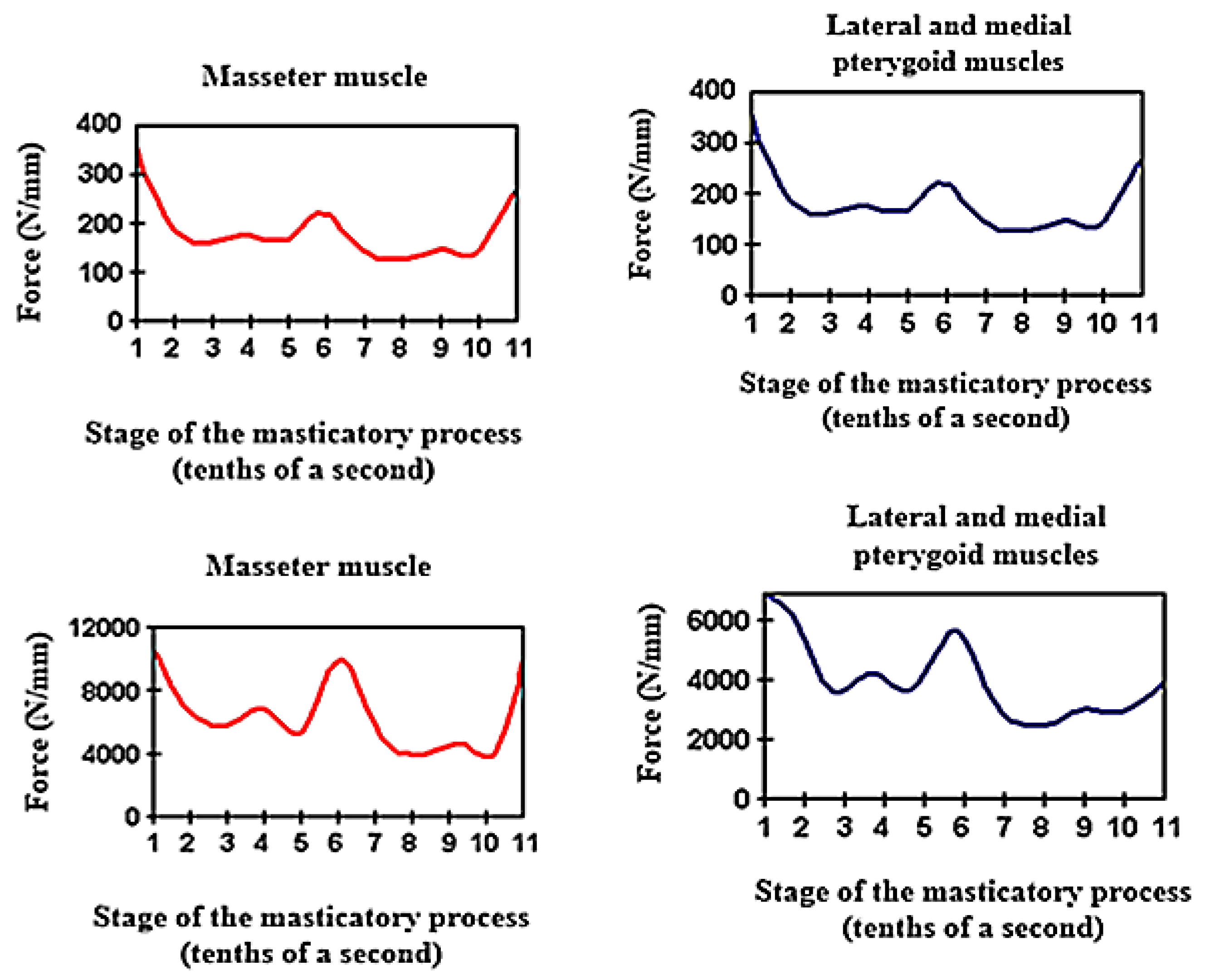
For the application of optimal forces to simulate physiological masticatory load, the main muscles of the mastication process, the masseter muscles and lateral and medial pterygoid muscles were taken into account (
Figure 1).
The average values of masticatory forces vary from individual to individual and are also influenced by food consistency. In this study, we applied an average force value of 220 N in the premolar area and 400 N in the molar area, introduced in the Autodesk Simulation Mechanical 2014 program (2014, San Rafael, California, US). The model was subjected to loading with a vertical force, applied, in turn, on the occlusal surfaces of each element of the dental bridge: both retainers and pontic. The modeling of an inlay-retained dental bridge was performed, with retainers on teeth 3.4 and 3.6 and pontic on 3.5 (
Figure 2). The material used for the bridge was a titanium alloy (Ti6Al4V) (Dentaurum, Germany).
The force was applied first in the contact area of the occlusal surface of the inlay at the level of 3.4, then at the occlusal face of 3.6 and then on 3.5, occlusal surface, simulating the pressure induced by the food fragment during the masticatory act.
FEM analysis consists of a mesh realization by splitting a solid volume into finite elements of parallelepiped or tetrahedron shape. Each element behaves individually, with the same characteristics as the base material. Depending on the pressure applied to every element, a specific load or temperature will be exerted and transmitted to the adjacent elements through nodes. For an enhanced accuracy of results, a condition was imposed for the mesh realization: the length between two nodes must always be the same. The model was exported to Autodesk Simulation Mechanical 2014 with a file ending in *. * Sat. These files are opened one by one in Autodesk Simulation Mechanical 2014. After determining the type of analysis (static stress), the mesh command was given.
Depending on the objectives of the analysis, the used material properties were: modulus of elasticity, Poisson’s ratio and density. The values for these parameters were taken from the literature [
9] (
Table 1).
We analyzed the tensions induced as a result of the application of these forces, on each element of the bridge, in the contact areas located between retainers and pontic and also on abutment teeth.
For the area where the bridge is in contact with the food fragment, during mastication, it is considered that there is no degree of freedom, and restrictions will be placed for all six movements. In Autodesk Simulation Mechanical 2014, these types of supports are represented by triangles.
3. Results
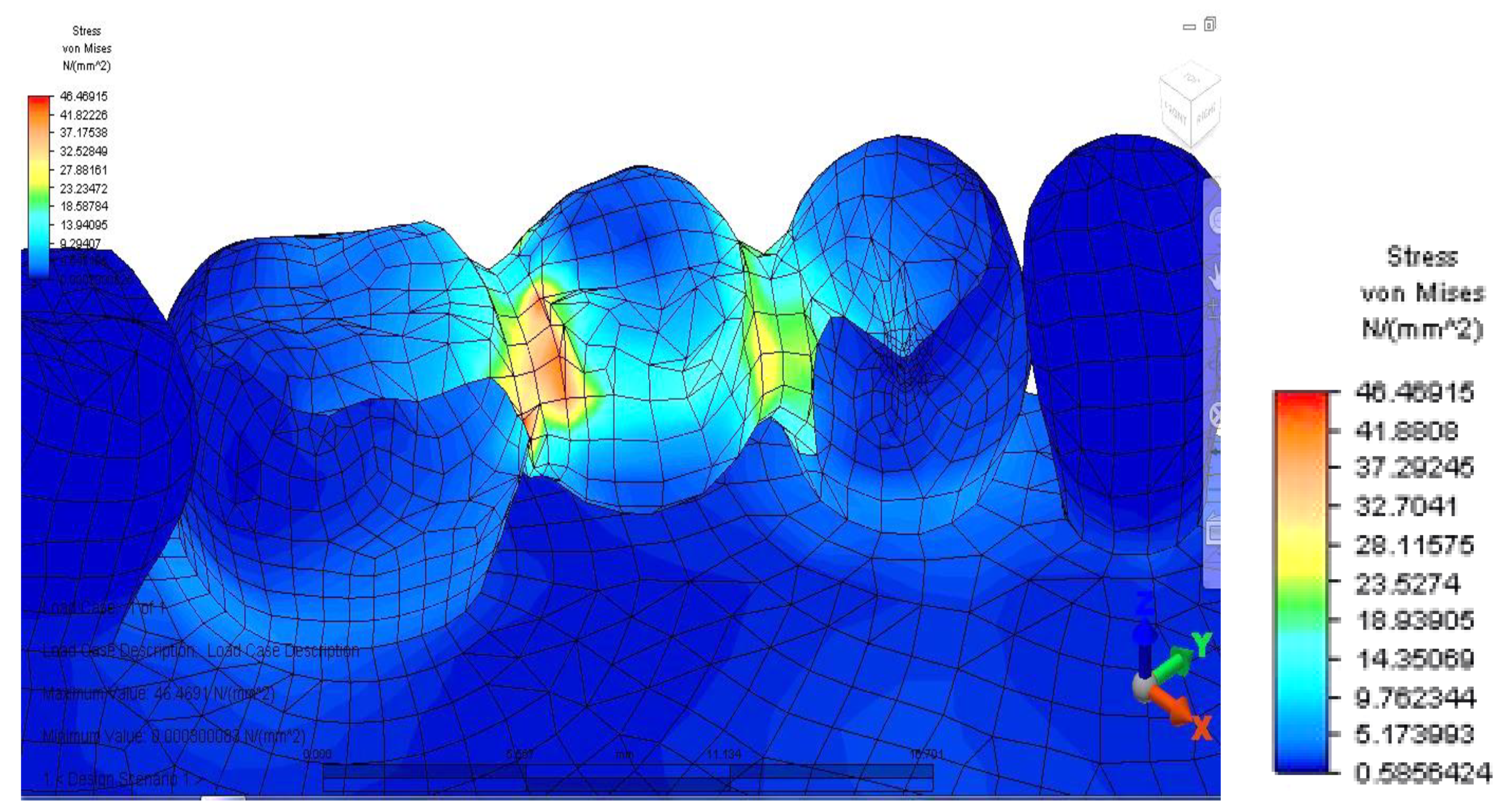
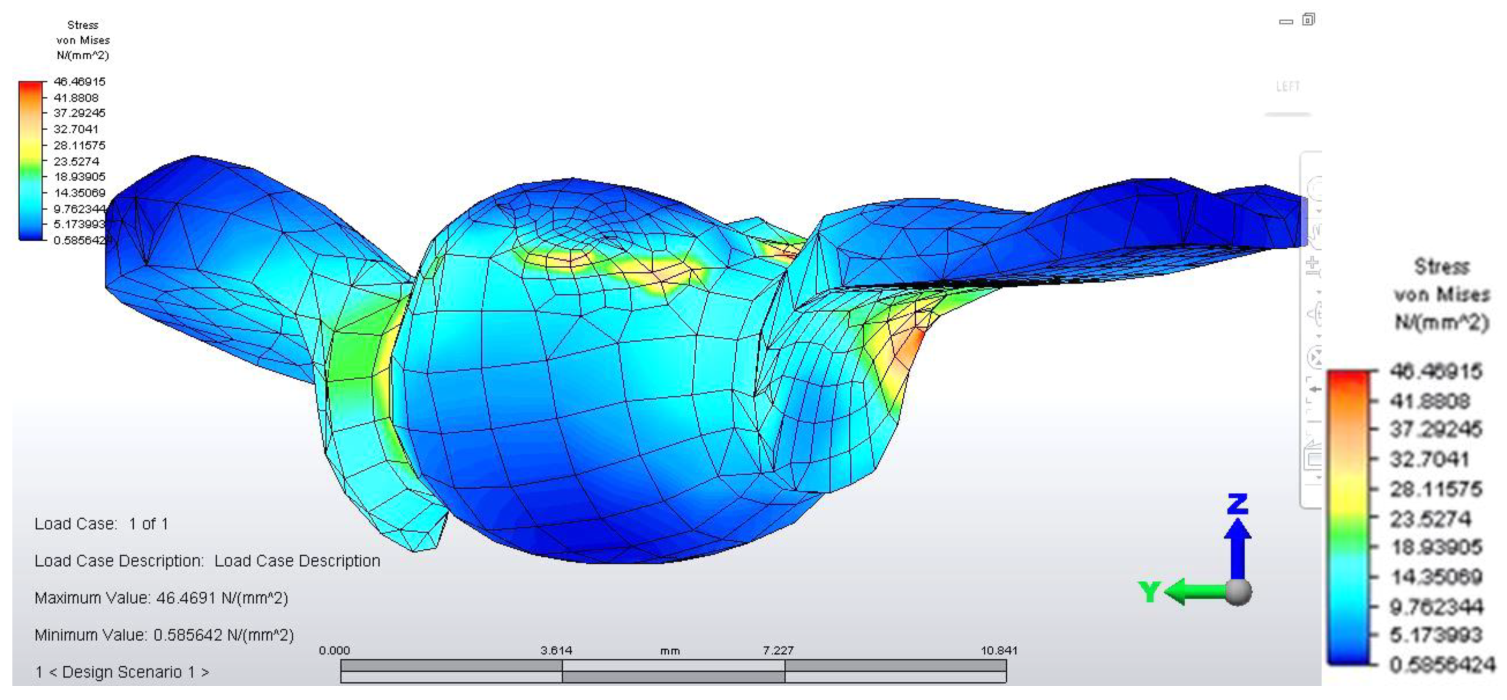
Once all the input data of the models were established, the analyze command was given. The results of the finite element analysis follow, according to the determination of loads applied to each area of the dental bridge. First, the distribution of deviatoric stresses (von Mises tensions) at the pontic level was analyzed when the reaction force, which opposes the muscular force, is located in the area of the missing premolar, 3.5 (
Figure 3).
From the model, we observed a higher tension on the prosthetic construction at the margin between the bridge and abutments. This phenomenon is related to the difference between the higher modulus of elasticity of the bridge alloy and the modulus of elasticity of abutment teeth. Furthermore, higher tensions develop at the junction between the bridge elements, and the maximum value is 46,469 MPa, between molar 3.6 and premolar 3.5. This high value of stress is explained by the smaller surface of the junction area.
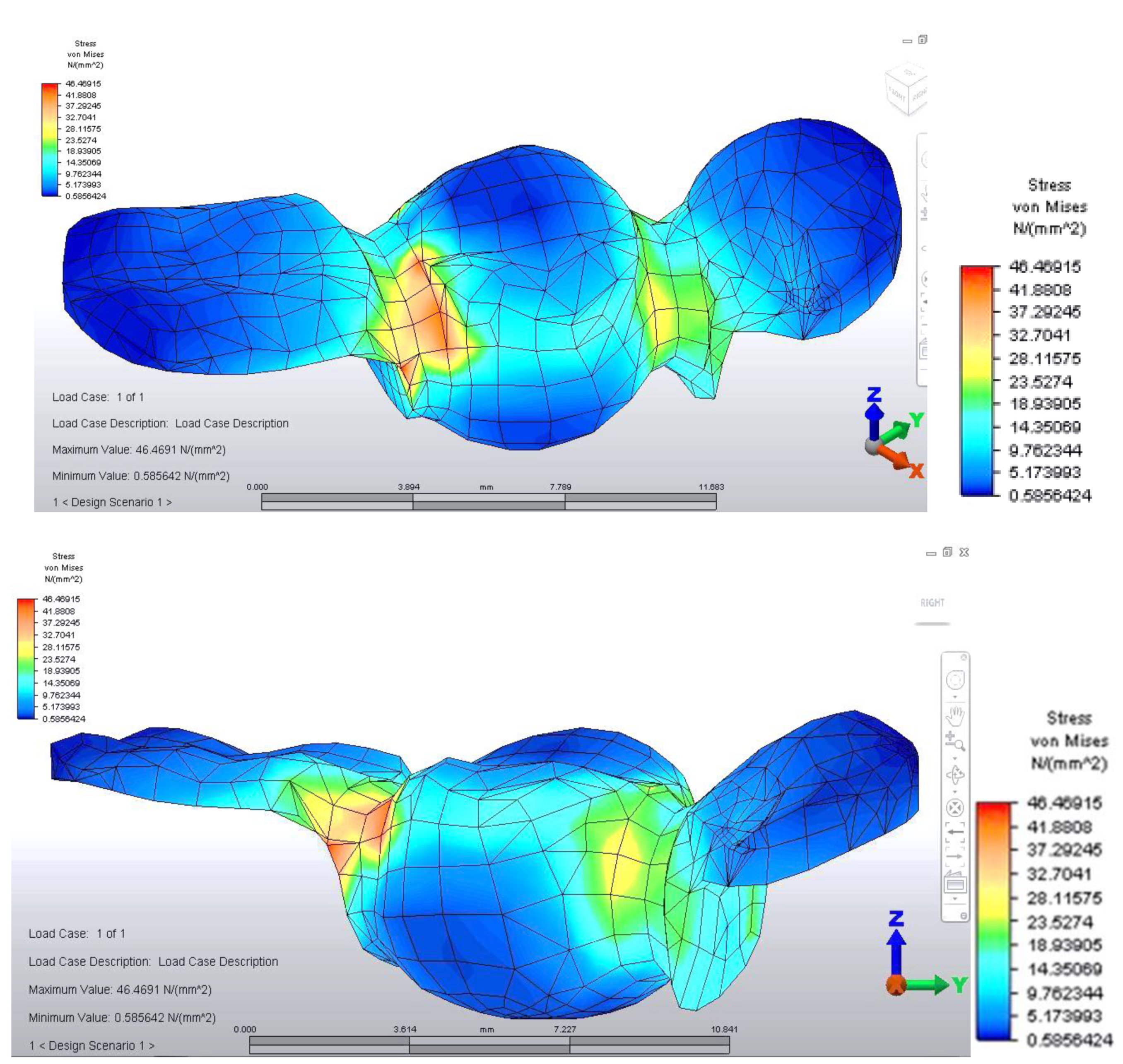
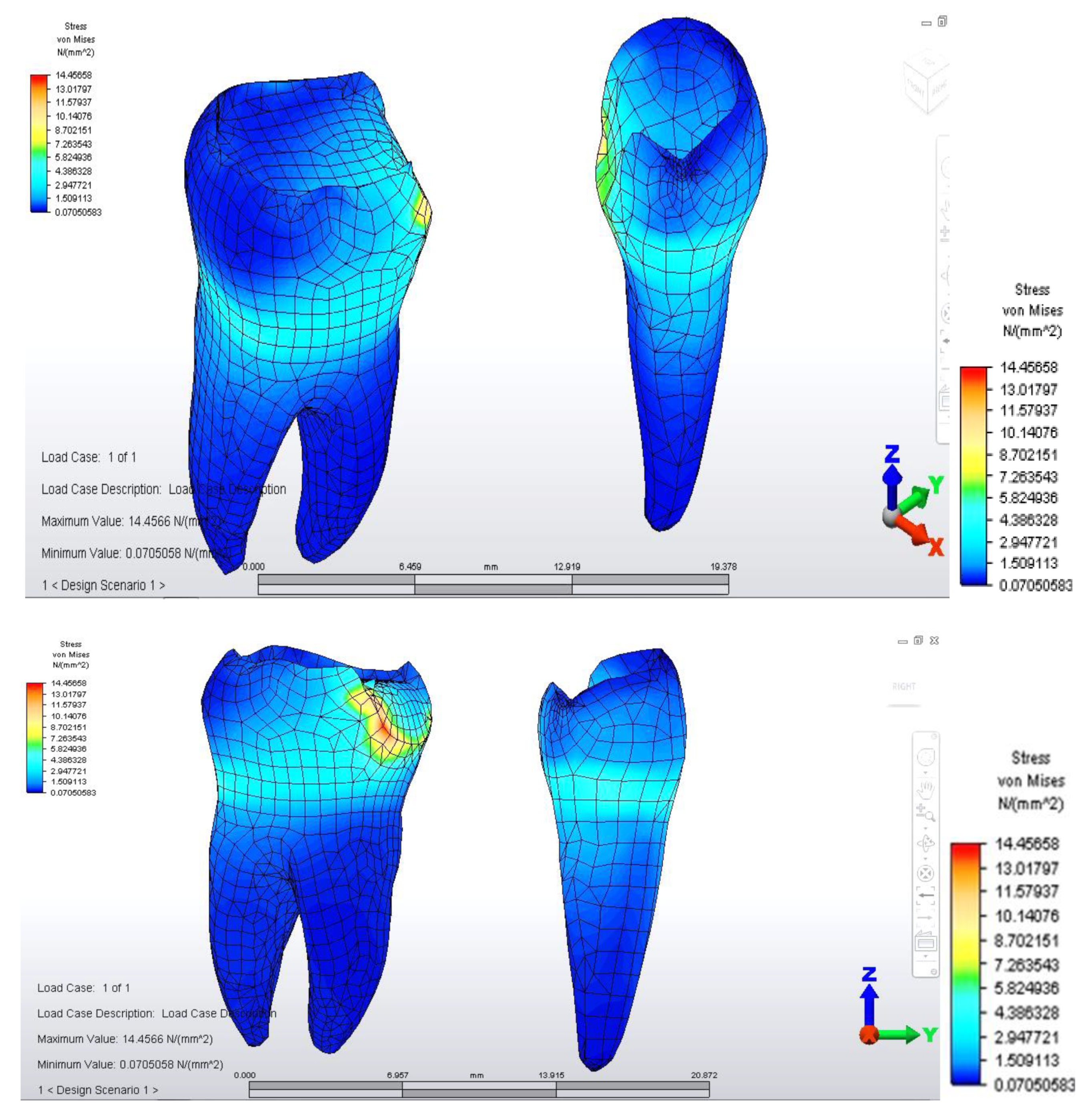
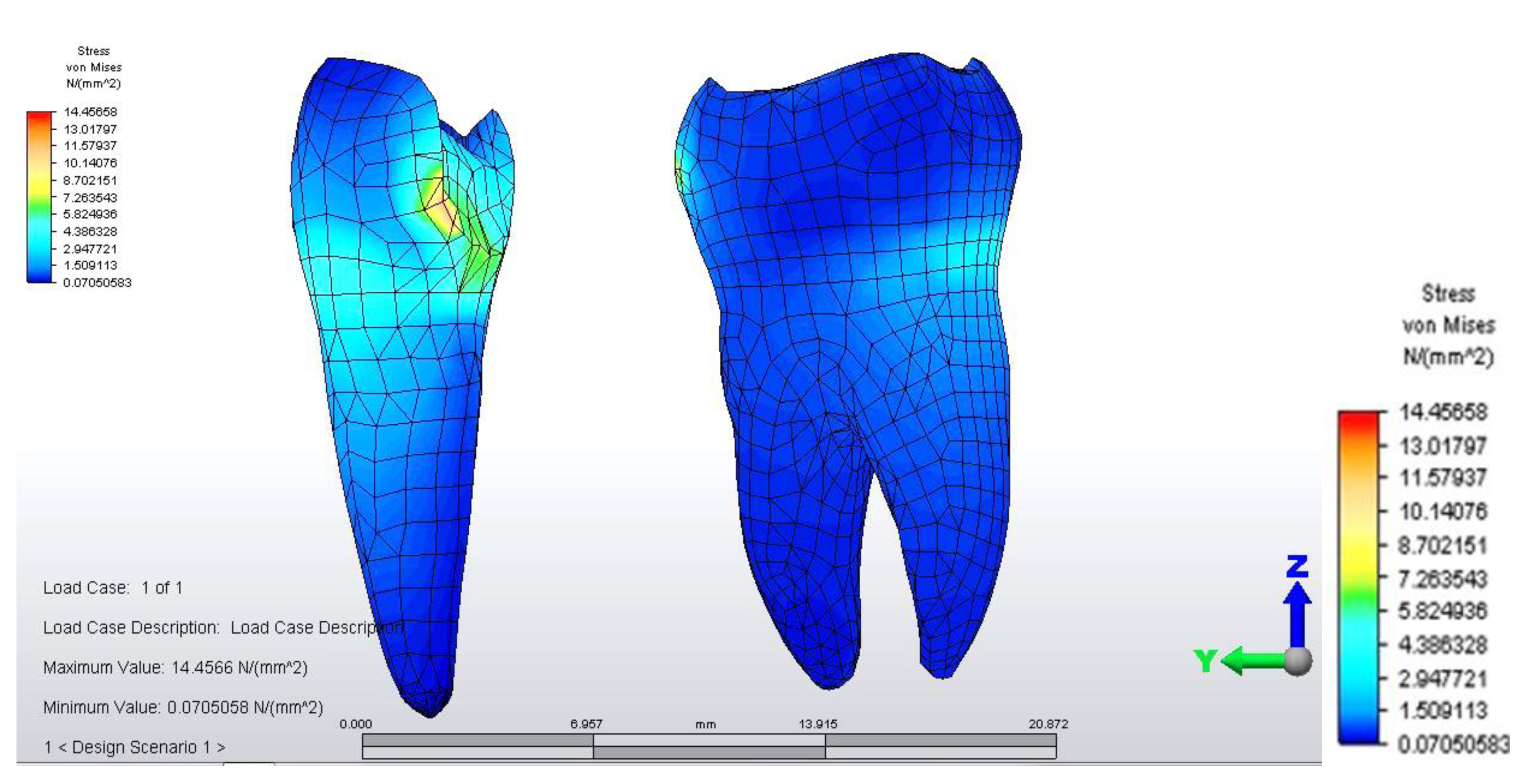
When analyzing stress values on abutment teeth, respectively molar 3.6 and premolar 3.4, they have a maximum value in the cervical area of the junction between teeth and bridge: the value of 14.456 MPa is equally distributed on the two abutment teeth (
Figure 4 and
Figure 5).
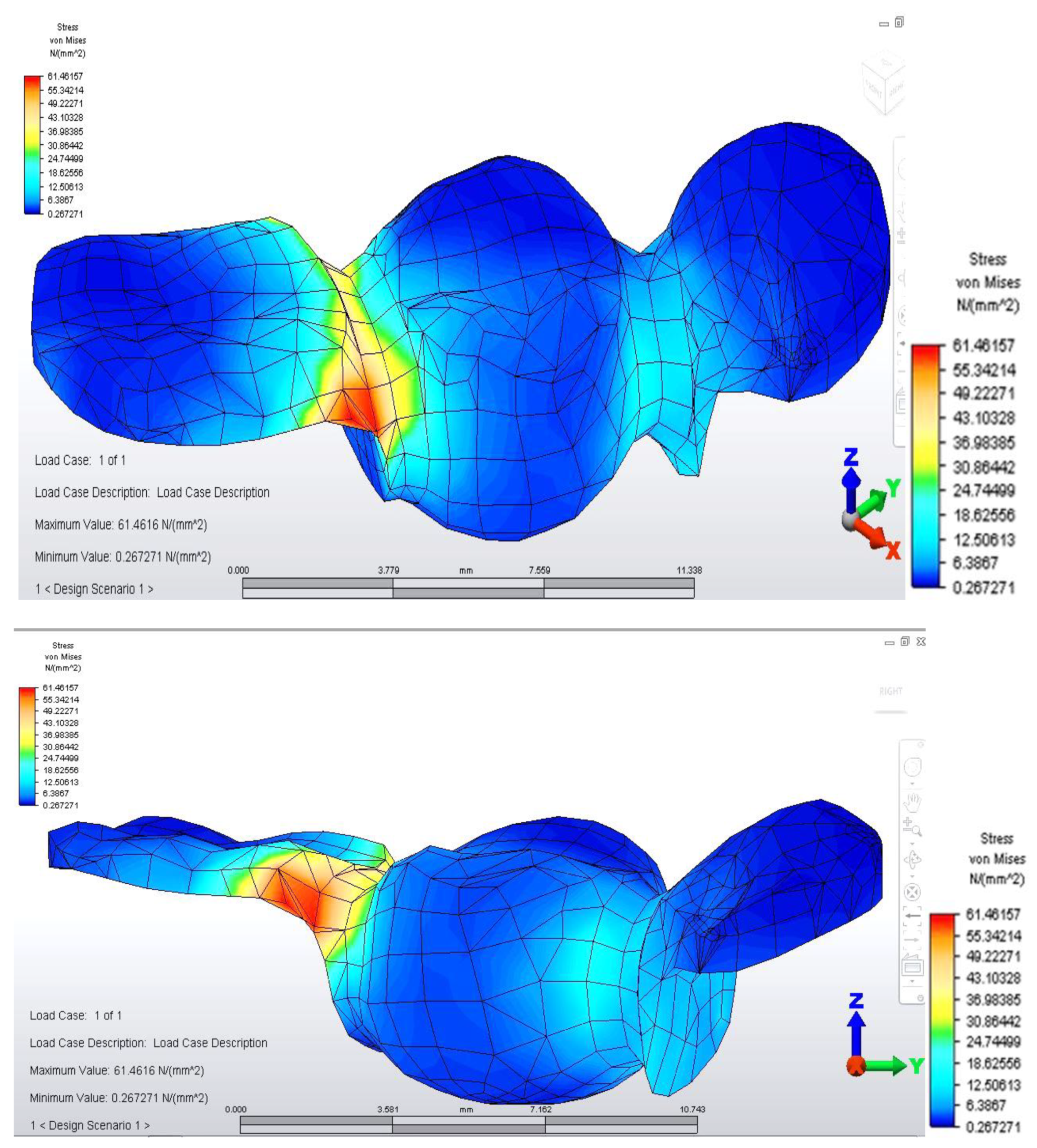
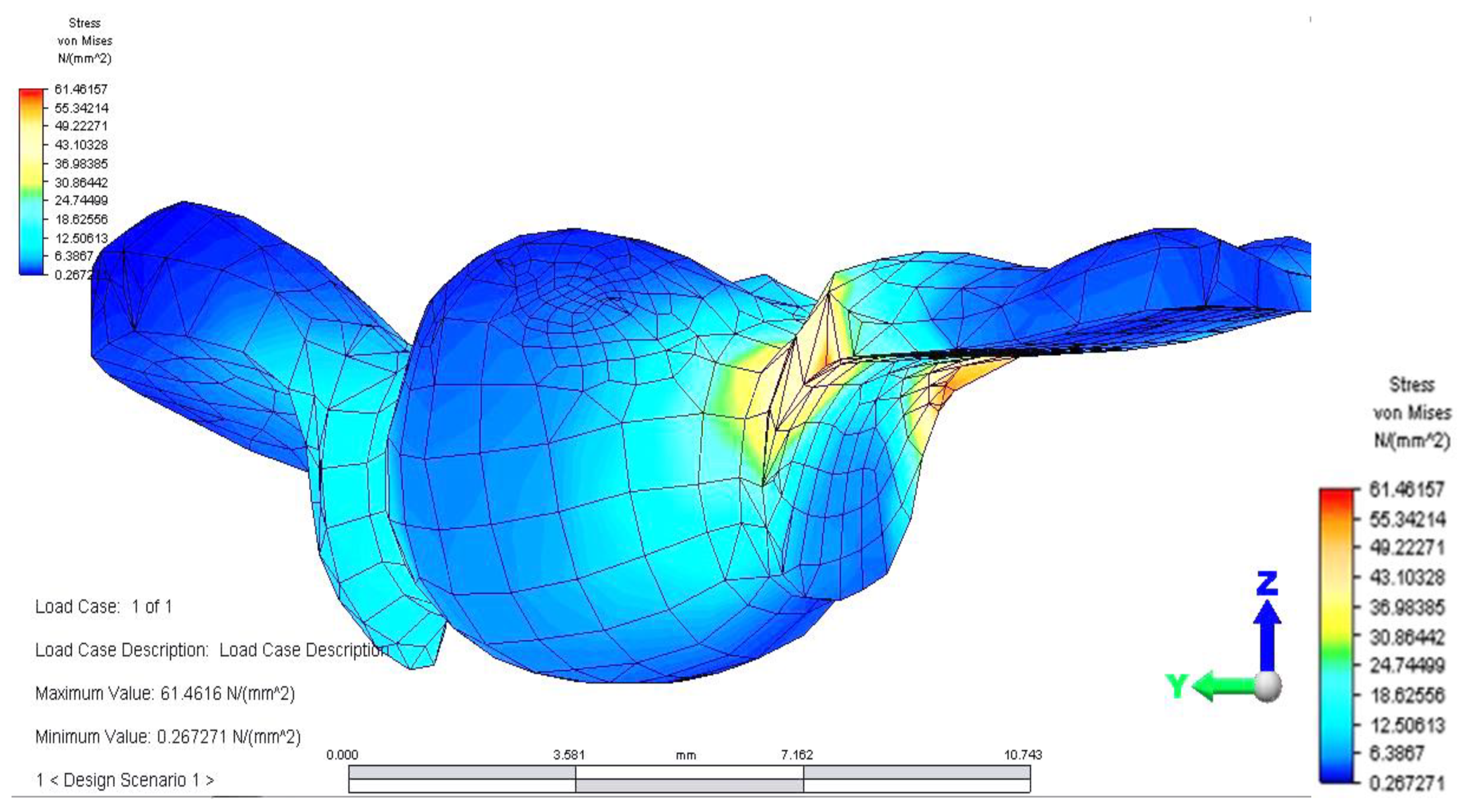
Distribution of tensions at bridge level was then observed in the situation where the reaction force, which opposes the muscular force, is placed in the area of molar 3.6 (
Figure 6).
This situation yielded a higher tension observed at the level of the bridge and at the mandibular bone level: the load is higher in the area of molar 3.6, where the reaction force is also applied.
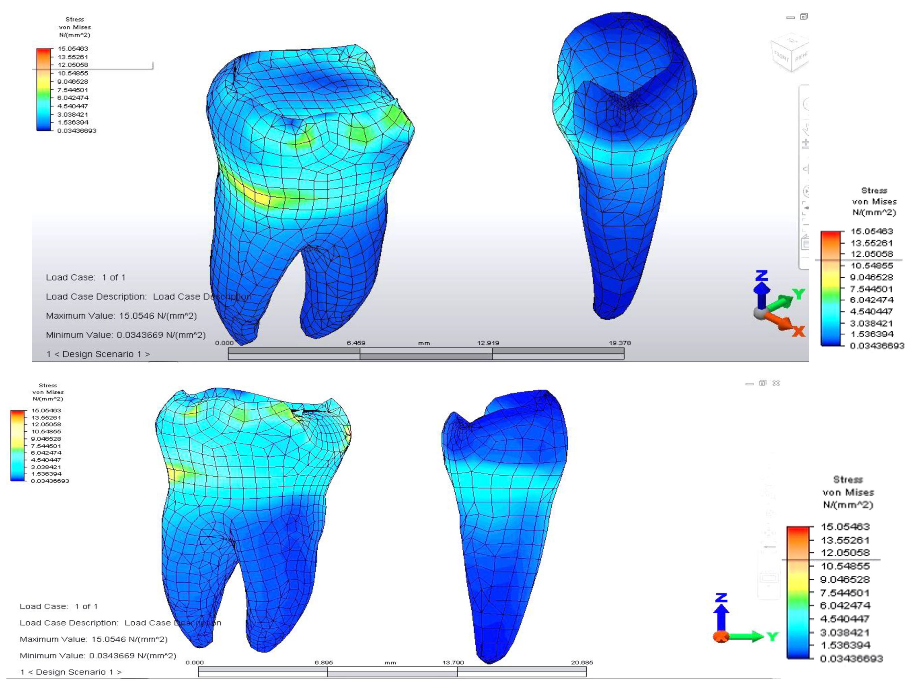
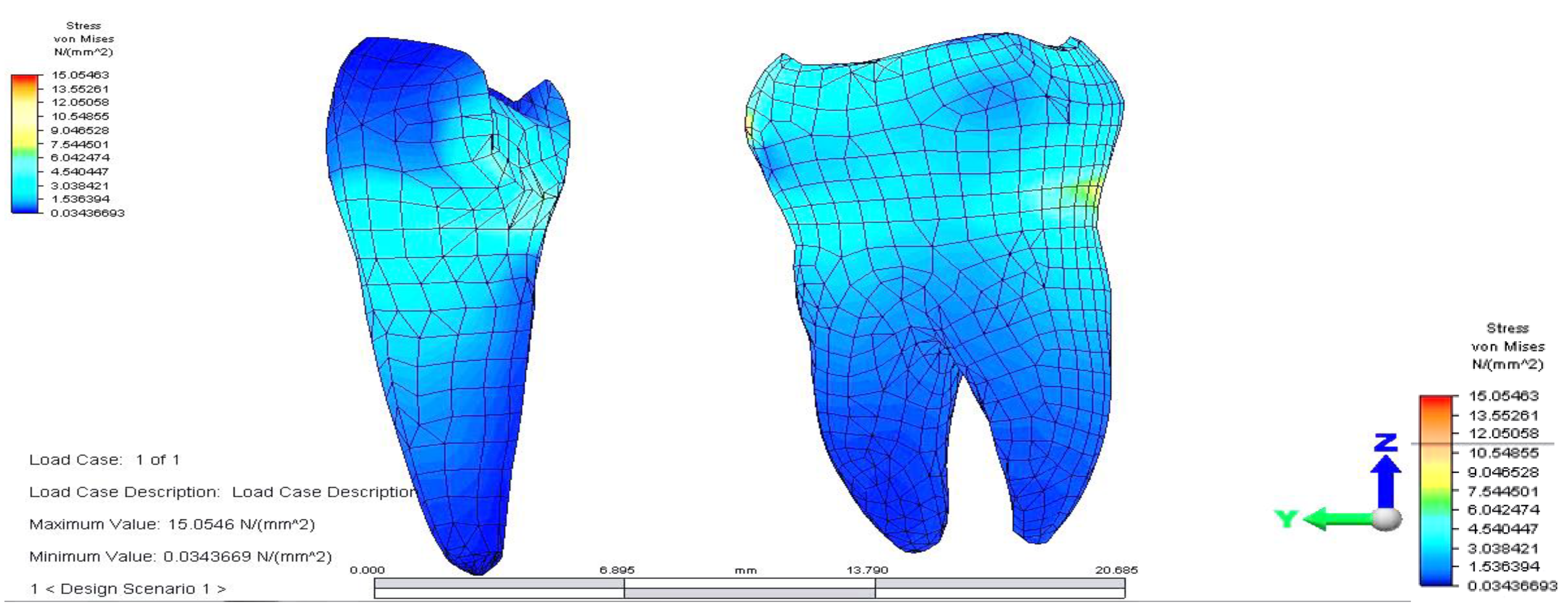
The distribution of stresses at the level of the dental crown revealed that there is increased stress at the junction area between the pontic and the retainer, on molar 3.6; its value of 61.461 MPa, being 1.5 times higher than in the previous case. Abutment teeth are subjected to a maximum tension of 15.054 MPa, the higher value being encountered in molar 3.6, both in the contact area with the bridge and in the area of contact with the mandibular bone, toward molar 3.7 (
Figure 7 and
Figure 8).
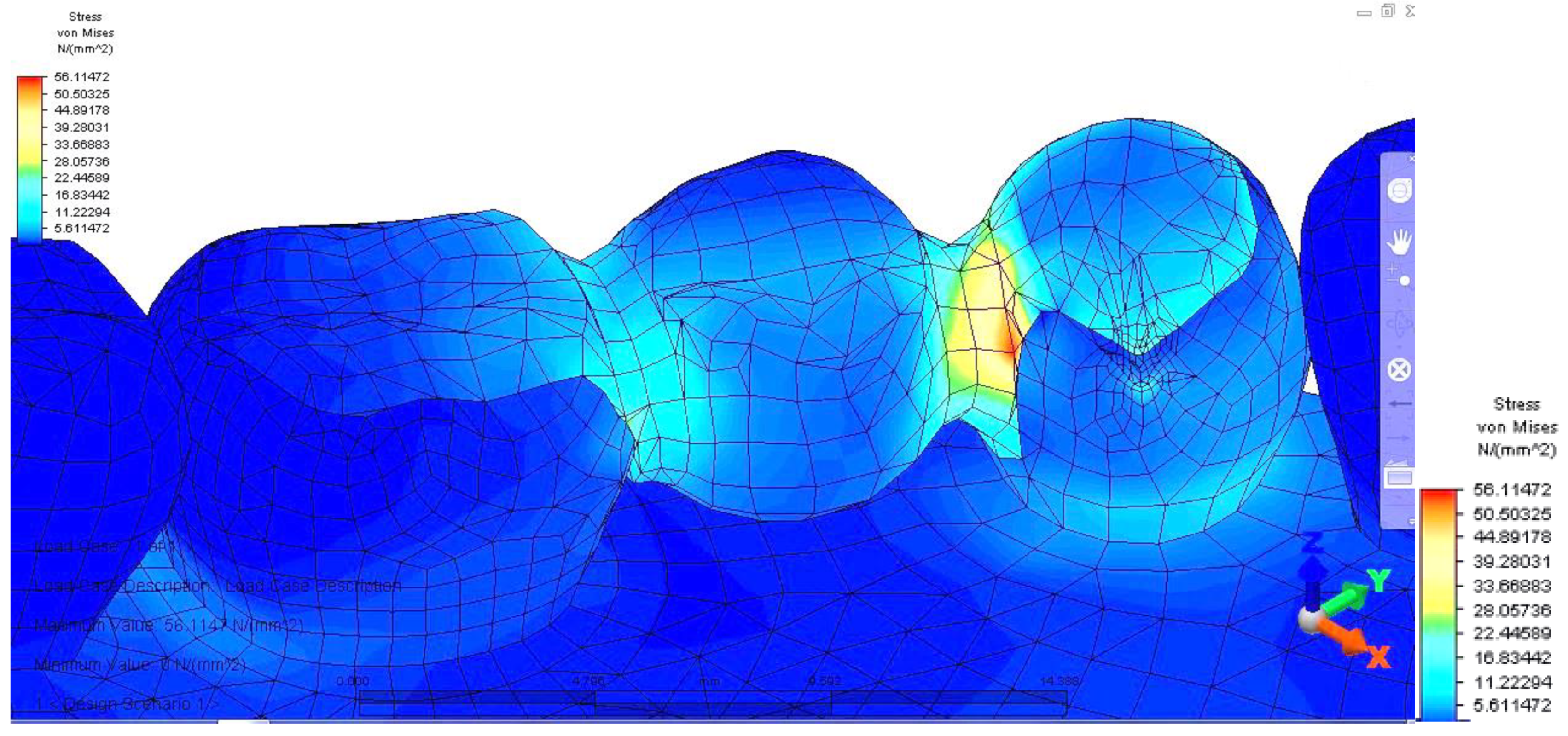
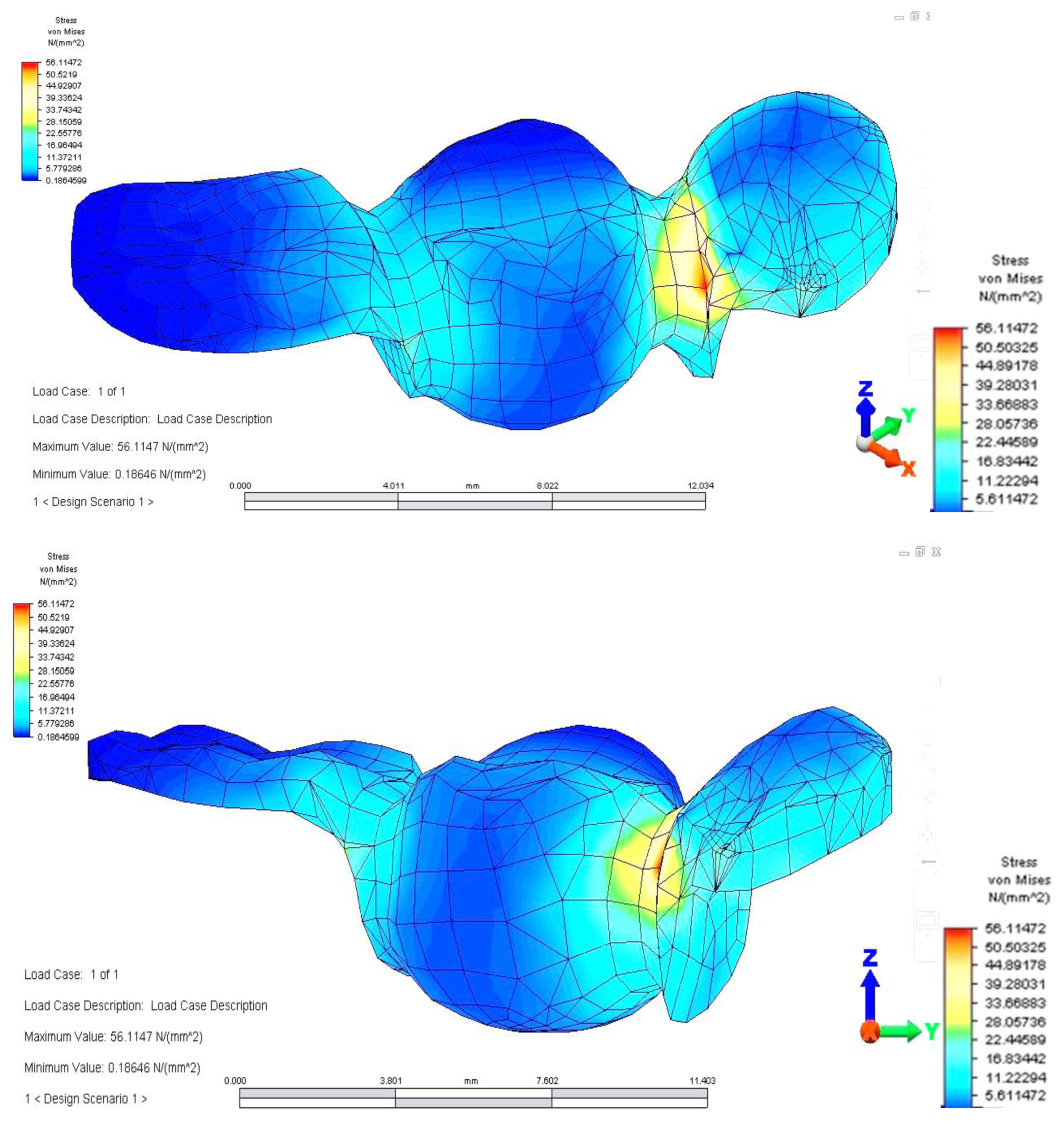
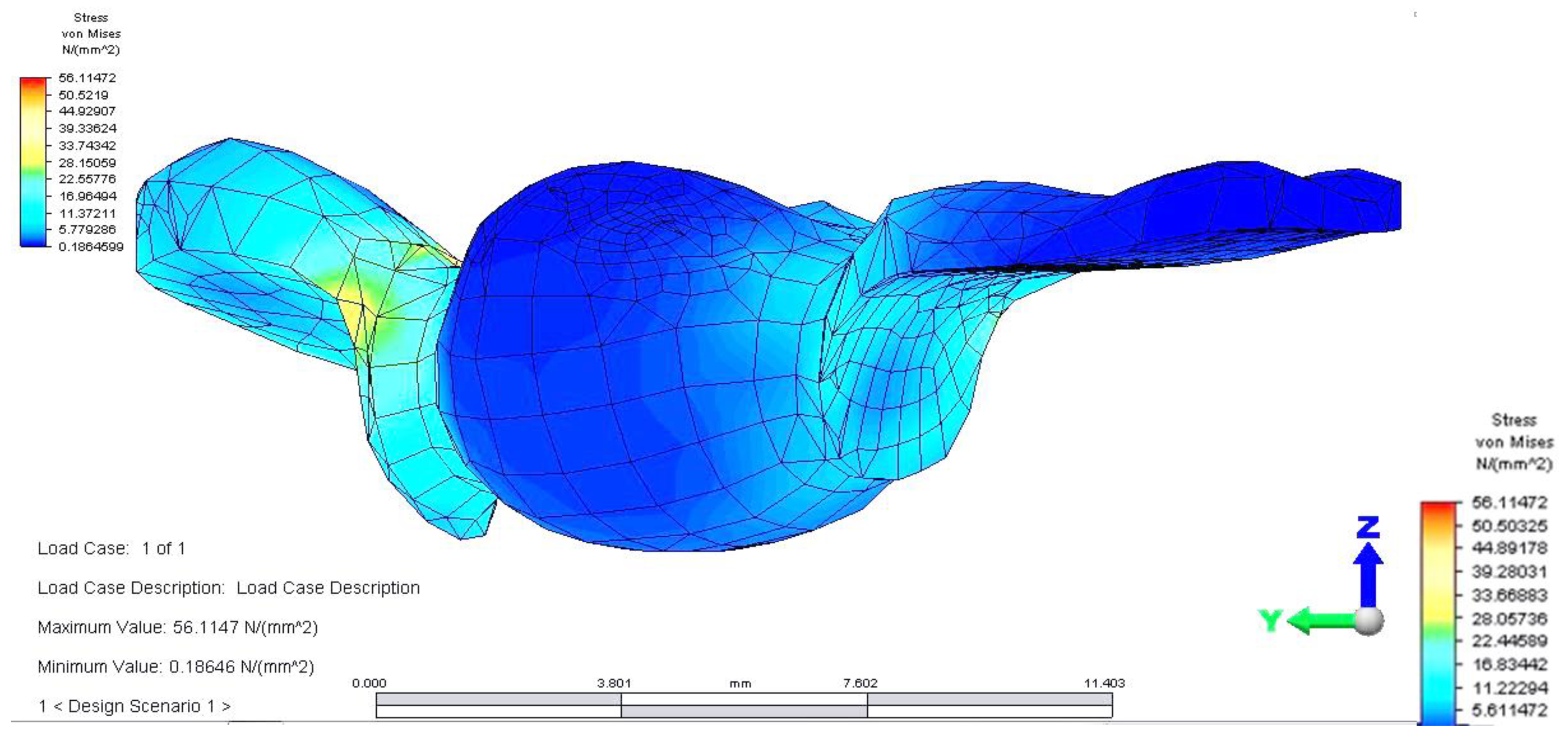
Regarding analyzing tensions in the mandible-abutments-dental bridge complex, when the reaction force acts on premolar 3.4, a tension jump is observed between the dental bridge and the teeth. This inequality is more evident at the junction between premolar 3.5 and the inlay applied on the occlusal surface of premolar 3.4. As a result of the reaction force exerted on tooth 3.4, the mandibular bone also supports a significantly higher tension (
Figure 9).
The dental bridge has an asymmetric stress distribution due to the reaction force, which has a maximum value of 56.114 MPa. However, the value is lower when the load is applied on the molar but higher when the force acts on the pontic. This is due to the greater distance of the premolar from the rotation center and also as a result of the direct action of the reaction force on premolar 3.4.
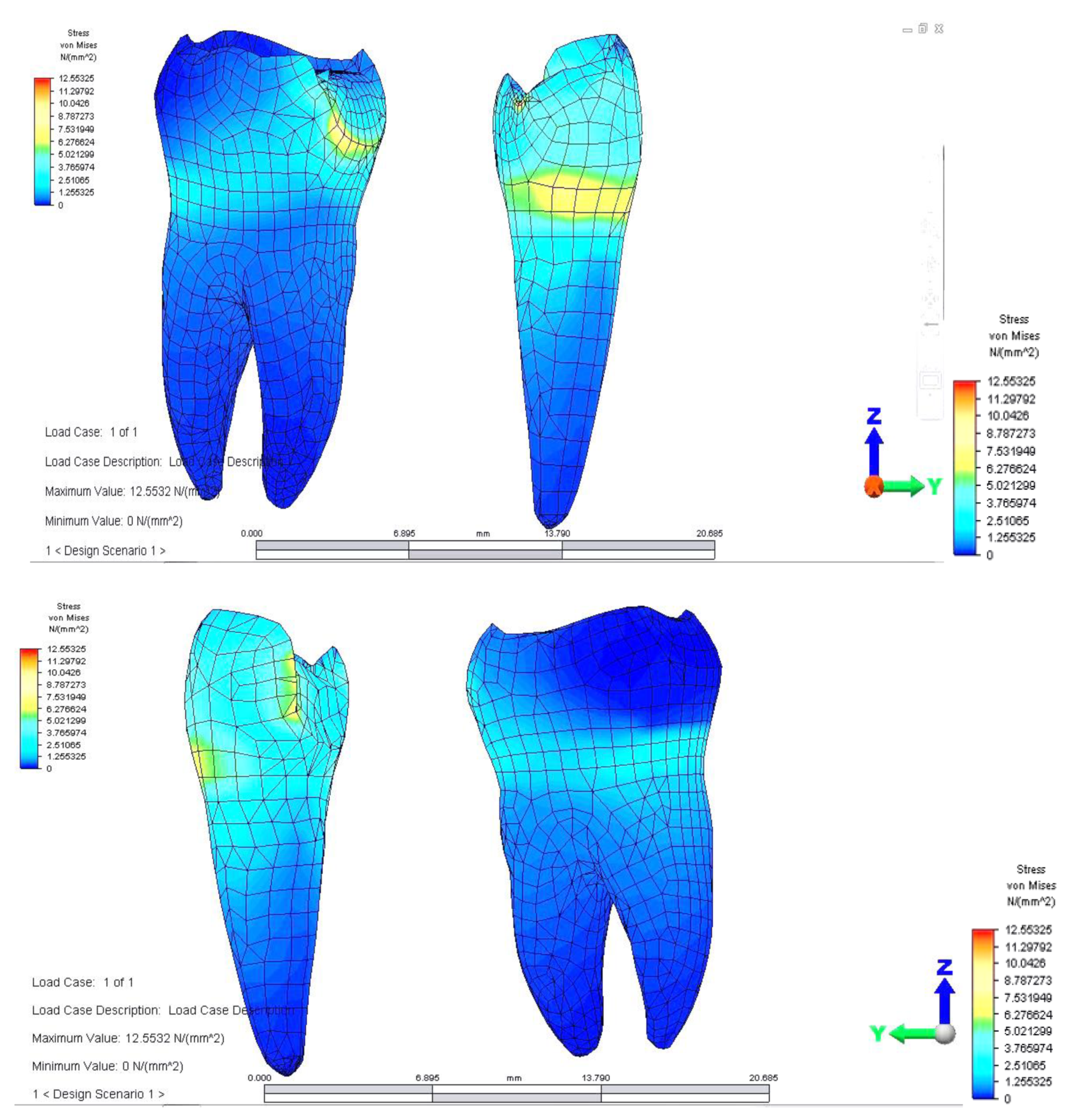
The pressure on abutments is also unevenly distributed. Stress distribution has a maximum value (12.553 MPa) on the premolar on which the reaction force acts. In addition, as in the case of applying for support on the molar, a higher value of tension is observed in the upper area of the root of premolar 3.4, towards the canine.
Both in this situation and in the previous case, the direct action of the reaction force on abutments also determines a tilt of the supporting teeth (
Figure 10 and
Figure 11).
If the load is applied to premolar 3.4, the mandibular bone has slightly higher tension values in the loading area. If the load is applied on molar 3.6, a jump in tension values is observed between the dental bridge and abutment tooth (
Figure 11).
4. Discussion
The finite element analysis, being a purely mathematical method, has a series of disadvantages because it imposes certain simplifications, which lead to a certain degree of approximation of results. This type of study does not take into account several important parameters that may influence clinical longevity of fixed prosthetic rehabilitation: anisotropy and heterogeneity of alveolar bone, periodontal structures, the viscoelastic response of periodontal structures to functional stresses, coefficients of thermal expansion of analyzed structures, the fatigue effect manifested by prosthetic restoration materials, the complexity of masticatory forces regarding their application point, intensity, summation of action forces with neighboring forces [
10]. In addition, the physiological mobility of supporting teeth and particularities of the mandibular bone were not taken into account—density, height, profile [
10].
Several authors reported that single implants with fixed prosthetic rehabilitation are the gold standard in the case of mono-edentulism in terms of success rate, patients’ reported outcomes and marginal bone loss [
11,
12].
In our study, the models were subjected to loading with a constant vertical force applied to different points on the occlusal surface of the bridge. However, in a real-life situation, masticatory forces are variable according to an individual’s food consistency and muscle activity.
Despite these limitations, finite element analysis provides valuable information and insight into the area of biomechanical research and offers clinical studies a base for development [
13,
14].
For this study, we chose to model an inlay retained dental bridge due to this being a model less studied in the literature. Furthermore, clinicians are reluctant to use this type of restoration because of a higher clinical failure percentage as a result of being a more technique-sensitive prosthetic solution. On the other hand, it is an important addition to the therapeutic options employed in clinical practice due to the fact that it can be used as a provisional prosthetic rehabilitation method during the 4-months period for bone healing and osteointegration of a dental implant [
15]. For this type of prosthesis, the most frequent failure causes are marginal leakage and debonding of restorations when compared to conventional fixed dental prostheses and single crowns supported by implant [
16]. Conversely, regarding advantages, it is a more conservative approach, as it can be applied to patients with contraindications of implant placement, and if executed properly, has a high success rate [
17].
In our study, when first developing the analysis, we evaluated the distribution of deviatoric stresses (von Mises tensions) at the pontic level, when the reaction force, opposing the muscular force, is located in the missing premolar 3.5 area. This phenomenon occurs due to the difference between the higher modulus of elasticity of the bridge alloy and the modulus of elasticity of abutment teeth. According to Hooke’s law, at the same specific deformation, located at the tooth-restoration interface and at different modulus of elasticity, higher stresses result in the prosthetic restoration. We noticed higher tensions developing at the bridge elements junction, the highest value being between teeth 3.6 and 3.5. This high value of stress is explained by the smaller surface of the junction area, which in turn could constitute a potential fracture point. This result is in concordance with other studies in the literature [
18].
Moreover, when evaluating the mandible-abutments-dental bridge as a whole, with the application of a reaction force on premolar 3.4, a tension jump is observed between the teeth and the dental bridge. This disparity is more obvious at the premolar 3.5 and the inlay applied on the occlusal surface of the junction with 3.4. The force is further transmitted to the mandibular bone due to increased stress, which upholds a considerably higher tension.
Results similar to ours were obtained in a study that analyzed three interim restorative materials by the FEM method regarding stress resistance. The authors found that the biggest tensile stress magnitude, regardless of the restorative material, was in the region of the prosthetic connector, and the highest stress peak was observed in resin composite, followed by polyetheretherketone and acrylic resin [
3].
The asymmetric stress distribution of the dental bridge is due to the placement of the reaction force. Thus when the load is applied to the molar, the value is lower. However, it is higher when the force is placed directly on the pontic. This situation can be explained because the premolar is further from the rotation center and the reaction force, which acts directly on tooth 3.4. Moreover, the abutments have an uneven stress distribution, the value being elevated on the premolar on which the reaction force acts, and an augmented value of tension is noticed in 3.4, towards the coronal area of the root, near the canine. In both analyzed scenarios, there is a tilt of the supporting teeth caused by the direct action of the reaction force on abutments.
A study by Bromicke evaluated the load-bearing capacity, load at initial damage and the failure pattern of posterior resin-bonded fixed dental prostheses to replace a maxillary first molar fabricated from veneered cobalt–chromium, veneered zirconia and monolithic zirconia. Of all tested models, veneered resin-bonded fixed prostheses were more prone to cracking of the veneer component [
19]. Other authors observed similar results, who compared fracture resistance of veneered zirconia and metal–ceramic inlay-retained fixed dental prostheses and pinpointed the veneer as being the weakest component [
20,
21].
Another study, which used the finite element method aimed at testing materials to restore a missing mandibular first molar, found no difference between a posterior inlay-retained full zirconia fixed dental prosthesis and a chromium cobalt substructure, porcelain coating, and adhesive resin as wings. The authors applied a load of 400 N and observed a slight advantage regarding stress-bearing for zirconia, however, not significantly when compared to the chromium cobalt substructure and porcelain coating [
22].
A study that analyzed tensile stress between restoration–cement, cement and cement–cavity observed that the tensile stress was directly proportional to the restorative materials elastic modulus. Thus a more rigid cement material increases tensile zones in the layer but decreases the stress between prosthesis and cement. The highest stress concentration between restoration and cement was observed in the molar cavity when compared to the premolar [
23].
Other factors that could further influence fracture resistance are the design of the preparation, framework design, and surface treatments of fixed dental prosthesis [
24,
25,
26]. A study demonstrated that the highest fracture resistance values were observed in the case of the butterfly wings design followed by inlay and box designs [
27]. Furthermore, the additional surface treatment by sandblasting and tribochemical silica coating of zirconia surfaces displayed the highest mean fracture resistance values when compared to Er, Cr: YSGG laser [
27,
28].
Bone density and width of maxillary bones in the edentate area have an important impact on the choice of the future prosthetic appliance, which can be applied. Thus instruments, which analyze these parameters are of utmost relevance, especially when considering implant placement. Furthermore, a mechanical risk evaluation before placing inlay-retained dental bridges or before placing other therapeutic options, especially implant treatment using endoral radiographs, ortopanoramics and cone-beam computer tomography and other paraclinical examinations, should be an obligatory step in treatment planning [
29,
30].
The most fragile part of the bridge is represented by the junction between the bridge body and aggregation elements; the smaller the section of this area, the more prone it will be to fracture [
31,
32]. Our study confirmed these results; furthermore, we also emphasized the distribution of forces on the bridge elements and on abutments, highlighting the areas of maximum load, as clinical maneuvers, such as periodontal instrumentation, can further weaken the resistance of abutment teeth [
33].
Knowing the vulnerable areas, clinicians will have useful information for designing such a dental bridge and will have the opportunity to increase stability and retention.
The results of our study show that the inlay-retained dental bridge represents an optimal therapeutic solution, in terms of the resistance of abutments, with the added benefit of an important economy of dental tissues.


 ,
, 


