Article

Adaptive Semi-Structured Mesh Refinement Techniques for the Finite Element Method

by
Adrian Amor-Martin
* and
Luis E. Garcia-Castillo
Signal Theory and Communications Department, University Carlos III of Madrid, 28911 Leganes, Spain
*
Author to whom correspondence should be addressed.
Appl. Sci. 2021, 11(8), 3683; https://doi.org/10.3390/app11083683
Submission received: 26 February 2021 / Revised: 10 April 2021 / Accepted: 14 April 2021 / Published: 19 April 2021
(This article belongs to the Special Issue Computational Electromagnetism)

Abstract

:

Featured Application

This work can improve the computational resources employed to achieve a given accuracy in electromagnetic simulation.

Abstract

The adaptive mesh techniques applied to the Finite Element Method have continuously been an active research line. However, these techniques are usually applied to tetrahedra. Here, we use the triangular prismatic element as the discretization shape for a Finite Element Method code with adaptivity. The adaptive process consists of three steps: error estimation, marking, and refinement. We adapt techniques already applied for other shapes to the triangular prisms, showing the differences here in detail. We use five different marking strategies, comparing the results obtained with different parameters. We adapt these strategies to a conformation process necessary to avoid hanging nodes in the resulting mesh. We have also applied two special rules to ensure the quality of the refined mesh. We show the effect of these rules with the Method of Manufactured Solutions and numerical results to validate the implementation introduced.

1. Introduction

The Finite Element Method (FEM) is a mature tool used to obtain the numerical solution of partial differential equations (PDEs) used in multiple engineering fields and physics [1,2,3,4]. Apart from the solid mathematical foundation of FEM, one of the main advantages of this technique is the use of adaptive refinement to improve the error convergence in the approximation of the field. This leads to better use of the computational resources since we obtain automatically more accurate solutions with fewer unknowns to solve. Additionally, the use of these techniques provides an estimation of the error in the problem. In FEM, we can perform h refinements (decreasing the size of the elements used for discretizing the original domain) and p refinements (increasing the order of basis functions that approximate the field under study). The combination of these two refinements leads to the so-called h p refinement [5,6,7], which might lead to exponential convergence when appropriate estimators are used.
The p refinements are especially effective when approximating smooth solutions, whereas h (also called mesh adaptive) refinements are more general and adapt to non-smooth solutions (e.g., bends, corners, or other special geometries).
A good compromise is the use of second-order basis functions [8], as in [9,10]. The field of application of h and h p adaptivity, [11,12,13,14,15,16], is quite broad: multigroup neutron diffusion [17], brittle fracture modeling [18], tomography [19], inverse scattering problems in electromagnetics [20], electromagnetic cloaking [21], acoustics [22], metamaterials [23], or mechanics [24]. However, these techniques are specific to hexahedral and tetrahedral meshes.
The use of different shapes depending on the geometry of the problem is advantageous from the computational point of view. We should use tetrahedra for irregular and unstructured geometries and hexahedra for rectangular-like geometries. The triangular prism can be considered as a hybrid of these two, and it can be used to connect hexahedral and tetrahedral meshes [25], whereas it is also well suited for planar geometries with an irregular pattern on the surface, e.g., laminates and sandwich structures [26,27] integrated circuit package designs [28], planar microwave circuits and antennas [29], waveguide sections [30], or coating for irregular volumes meshed with tetrahedra. Additionally, the generation of volumetric meshes for prisms is typically easy since we only need to extrude a 2D triangular mesh.
We need to introduce adaptivity techniques to all the different shapes to choose the most suitable shape for each problem. Unfortunately, the application of adaptivity techniques to triangular prisms is not so frequent in the literature apart from [31,32]. Whereas the formulation and the definition of the estimator do not depend on the discretization shape, the development of marking strategies and the application of different h refinements need to be particularized for the different shapes.
Here, we suggest to take the fundamental ideas from 2D refinement and apply them rigorously to the adaptivity with triangular prisms, solving the particularities (especially related to maintaining admissible meshes in the sense of having conformal solutions from the FEM point of view straightforwardly) that arise from the application of these ideas to volumetric meshes. First, we use the Method of Manufactured Solutions, MMS [33], to show the significance of the mesh quality indicators we have introduced and to experiment with five different marking strategies of the elements to be refined. Then, we validate our implementation with a propagation problem (specifically, a WR-90 rectangular waveguide). Finally, we show with an L-shaped waveguide section the effectiveness of the adaptivity algorithm.
The rest of the paper is structured as follows: In Section 2, we detail each different step of the adaptivity algorithm. In Section 3, we provide meaningful experiments with MMS and propagation problems to show the performance of the adaptivity refinement developed in the previous section. Finally, we draw the conclusions that can be extracted from this work in Section 4.

2. Methods

Every adaptive algorithm needs four steps:
  • Solve the electromagnetic domain under study.
  • Estimate how accurate the approximation of the fields is.
  • Mark the elements we want to refine to improve the accuracy.
  • Refine the defined elements in the previous step.
We repeat these four steps until we achieve a threshold of the estimated error or after a number of iterations is run. This section explores each of these steps separately.

2.1. Variational Formulation

We assume that the domain Ω of the electromagnetic problem to be solved is a smooth domain for which we have the following boundary value problem:
× ( μ r 1 × E ) k 0 2 ε r E = F in Ω ,
n ^ × ( E × n ^ ) = Ψ D on Γ D ,
n ^ × ( μ r 1 × E ) = Ψ N on Γ N ,
n ^ × ( μ r 1 × E ) j k 0 n ^ × ( E × n ^ ) = Ψ C on Γ C ,
taking the electric field E as the field to approximate. We decompose the boundary of the domain Ω into the sets Γ D , Γ N , and Γ C , corresponding to Dirichlet, Neumann, and Cauchy boundary conditions, respectively. We set k 0 , ε r , and μ r as the vacuum wavenumber, relative electric permittivity, and relative magnetic permeability, respectively. The vector n ^ is the outward unit normal vector regarding Ω . We assume isotropic and homogeneous materials without loss of generality. The terms F , Ψ D , Ψ N , and Ψ C are used for the volumetric excitation and non-homogeneous boundary conditions. If we are not using MMS, F , Ψ D , and Ψ N are set to 0 .
We use the space of functions [1],.
H ( curl , Ω ) : = w [ L 2 ( Ω ) ] 3 | × w [ L 2 ( Ω ) ] 3 , .
to approximate the electric field due to its nature. The space L 2 ( Ω ) is the space of square-integrable functions over Ω . We also use the subspace H 0 ( curl , Ω ) , whose functions enforce Dirichlet boundary conditions. We define the sesquilinear forms:
w , v Ω = Ω w * · v d Ω ,
w , v Γ = Γ w * · v d Γ ,
using * to denote complex conjugation, Ω as a given volume, and Γ as a specific surface.
Applying the Galerkin method yields:
Find E H 0 ( curl , Ω ) such that
× w , μ r 1 × E Ω k 0 2 w , ε r E Ω + j k 0 n ^ × w , n ^ × w Γ C = w , F Ω n ^ × ( w × n ^ ) , Ψ N Γ N n ^ × ( w × n ^ ) , Ψ C Γ C w H 0 ( curl , Ω ) .
The solution to this problem is obtained by solving the system of equations obtained after the discretization of the domain into second-order triangular prisms from [10].

Method of Manufactured Solutions

The MMS consists of the manufacture of an analytical solution to a differential equation by solving the problem backward. If we take an equation D ( E ) = f , assuming that D is a differential operator and f is a source term, the first step is to manufacture f MMS employing the introduction of an analytic solution E MMS . Afterwards, we solve the differential equation obtaining the approximate solution E FEM that can be compared to E MMS to assess the quality of the approximation.
The excitations that we use in (7) are
F = × μ r 1 × E MMS k 0 2 ε r E MMS
Ψ D = n ^ × ( E MMS × n ^ )
Ψ N = n ^ × ( μ r 1 × E MMS )
Ψ C = n ^ × ( μ r 1 × E MMS ) j k 0 n ^ × ( E MMS × n ^ )
We use MMS in Section 3.1 to show the effect of the different marking strategies and the impact of the rules introduced in the algorithm to improve the quality of the adapted mesh.

2.2. Estimator

For computational purposes, the estimator of the areas where the accuracy of the solution would benefit more to have smaller elements should be cheap to compute. We use a straightforward local estimator based on [34], although other good alternatives are [35,36,37]. We compute the estimator individually for each element m with a volumetric residual R vol ( m ) , defined through
R vol ( m ) = × μ r 1 ( × E FEM ( m ) ) k 0 2 ε r E FEM ( m ) F ,
and a face residual R face ( m ) that changes if a boundary condition is present in that face. Thus, we define the residuals R D , R N , and R C for the Dirichlet, Neumann, and Cauchy boundary conditions, respectively, as
R D ( m ) = n ^ ( m ) × ( E FEM ( m ) × n ^ ( m ) ) Ψ D , on Γ D ,
R N ( m ) = n ^ ( m ) × μ r 1 ( × E FEM ( m ) ) Ψ N , on Γ N ,
R C ( m ) = n ^ × μ r 1 ( × E FEM ( m ) ) j k 0 n ^ ( m ) × ( E FEM ( m ) × n ^ ( m ) ) Ψ C , on Γ C .
We also use the tangential continuity of the magnetic field (not imposed explicitly) as the face residual R neigh for faces that belong to both elements m and n, i.e.,
R neigh ( m ) = n ^ ( m ) × μ r 1 ( × E FEM ( m ) ) + n ^ ( n ) × μ r 1 ( × E FEM ( n ) ) ,
so R face ( m ) = R D ( m ) R N ( m ) R C ( m ) R neigh ( m ) for each face in the m-th element.
Adding up all the residuals, we introduce the residual for each element m, which is introduced through
R ( m ) = h ( m ) R vol ( m ) , R vol ( m ) m + k 5 K k h k ( m ) R face , k ( m ) , R face , k ( m ) k ,
where K k is 1 2 and 1 for triangular and rectangular faces, respectively. Moreover, h is the diameter of the entity (volume or face). Note that the sesquilinear forms are local to the element m or a given face k.

2.3. Marking Strategies

We use five different marking strategies, i.e., algorithms that decide which elements are refined in terms of the local residual defined in Section 2.2:
  • Next-step estimator: inspired by [38], it is based on the estimation of the error that an element would have when refined.
  • Quantile: here, we order the elements from highest to lowest residual and we refine a given percentage, as shown in [39].
  • Maximum: we define a threshold relative to the maximum residual in the mesh (using a parameter θ [ 0 , 1 ] ) [40].
  • Fixed-energy fraction: we order the elements by their residual from highest to lowest, and we refine the first elements which constitutes a given percentage of the energy of the residual in the whole problem [41].
  • SER (Solve-Estimate-Refine): we combine here the fixed-energy fraction and maximum strategies [42]. We mark sets of elements (ordered from highest to lowest residuals) which are smaller and smaller (determined by a varying Heaviside step function) to achieve a given percentage of the energy of the whole problem. If the step function is forced to select only one element, we have the fixed-energy fraction strategy.
All of these strategies have been tested with unstructured meshes, i.e., with triangles or tetrahedra. We need to introduce modifications to these techniques for them to be applied to semi-structured meshes. In particular, we use a process of conformation to avoid the well-known issue of hanging nodes [6]. We have a hanging node when a direct correspondence of basis functions cannot be established between neighbor elements: e.g., when the edge of one element starts in the middle of the edge of the neighbor element. We could use special strategies to remedy this problem [6], but they are out of the scope of this work. This conformation process makes undetermined the number of prisms to be refined in the marking step, since the refinement has to be propagated horizontally and vertically.
We call P the set of elements of the original domain P , whereas P R is the set of elements marked to be refined, with P R P . In Algorithm 1, we suggest a variation (introducing an adaptive threshold to guarantee that, in each round, some elements are marked) of the algorithm proposed in [38], assuming that the residual follows asymptotically R = c h λ after a first uniform refinement.
Algorithm 1 Marking strategy using the next-step estimator inspired by [38]
  • Require: R k 1 ( m )
  • Require: conform _ refinement ( P R )
  • Input: R k ( m )
  • Input: P
  • Output: P R
1:
proceduremark_nextstep( R k ( m ) , P , P R )
2:
     θ ← 1
3:
    i← 0
4:
    if k = 1 then
5:
         R 2 ( e ) 0 e P
6:
    else
7:
        for all e P do
8:
            R k + 1 ( e ) ( R k ( e ) ) 2 / R k 1 ( e )
9:
        end for
10:
    end if
11:
    while N R = 0 do
12:
         θ θ / 10 i
13:
         ς cut θ · max { R k + 1 ( 1 ) , , R k + 1 ( N ) }
14:
        for all e P do
15:
           if R k ( e ) ς cut then
16:
                e P R
17:
           end if
18:
        end for
19:
        i i + 1
20:
    end while
21:
     P R conform _ refinement ( P R )
22:
end procedure
  • ▹ Estimator of the last step
  • ▹ Process of conformation to avoid hanging nodes
  • ▹ Evaluation of (12)
  • ▹ Set of original elements (of size N)
  • ▹ Set of elements marked to be refined (of size N R )
  •  
  •  
  • ▹ Number of iterations of mark_nextstep
  • ▹ To force a first round of uniform refinement
  •  
  •  
  • ▹ Go through each element
  •  
  •  
  •  
  •  
  • ▹ Adjustment of ς cut
  • ▹ Threshold to be marked
  •  
  •  
  • ▹ Add to the set of marked elements
  •  
  •  
  • ▹ Increase the iteration number
  •  
  • ▹ Conform marked elements
  •  
We include the algorithm for the quantile marking strategy in Algorithm 2. We adapt the implementation to the presence of the conformation process: we perform an iteration considering fewer and fewer elements until the number of elements to be refined is lower than the given percentage (specified through parameter θ ) of elements to be refined.
The maximum marking strategy does not require special treatment due to the conformation of the mesh, as shown in Algorithm 3, in contrast to the slight modifications introduced in the fixed-energy fraction and SER algorithms, included in Algorithms 4 and 5, respectively.
Algorithm 2 Quantile marking strategy based on [39]
  • Require: conform _ refinement ( P R )
  • Require: order _ residual ( R k )
  • Input: R k ( m )
  • Input: θ
  • Input: P
  • Output: P R
  •  
1:
proceduremark_quantile( R k ( m ) , θ , P , P R )
2:
     θ R θ
3:
     P ord order _ residual ( R k )
4:
    while N R < θ N do
5:
        for all e θ R · N R do
6:
            e P R
7:
        end for
8:
         P R conform _ refinement ( P R )
9:
         θ R θ 0.05
10:
    end while
11:
end procedure
  • ▹ Process of conformation to avoid hanging nodes
  • ▹ Order elements from highest to lowest local residual R k ( m )
  • ▹ Evaluation of (12)
  • ▹ Percentage of elements to be refined
  • ▹ Set of original elements (of size N)
  • ▹ Set of elements marked to be refined (of size NR)
  •  
  •  
  •  
  • ▹ Get an ordered set of elements
  •  
  •  
  • ▹ Add to the set of marked elements
  •  
  • ▹ Conform marked elements
  • ▹ Try with a smaller set
  •  
  •  
Algorithm 3 Maximum marking strategy
  • Require: conform _ refinement ( P R )
  • Input: R k ( m )
  • Input: θ
  • Input: P
  • Output: P R
  •  
1:
proceduremark_maximum( R k ( m ) , θ , P , P R )
2:
     ς cut θ · max { R k ( 1 ) , , R k ( N ) }
3:
    for all e P do
4:
        if R k ( e ) ς cut then
5:
            e P R
6:
        end if
7:
    end for
8:
     P R conform _ refinement ( P R )
9:
end procedure
  • ▹ Process of conformation to avoid hanging nodes
  • ▹ Evaluation of (12)
  • ▹ Percentage to set threshold
  • ▹ Set of original elements (of size N)
  • ▹ Set of elements marked to be refined (of size N R )
  •  
  •  
  • ▹ Threshold to be marked
  •  
  •  
  • ▹ Add to the set of marked elements
  •  
  •  
  • ▹ Conform marked elements
  •  
Algorithm 4 Fixed-energy fraction marking strategy
  • Require: conform _ refinement ( P R )
  • Require: order _ residual ( R k )
  • Input: R k ( m )
  • Input: θ
  • Input: P
  • Output: P R
  •  
1:
proceduremark_fixedenergy( R k ( m ) , θ , P , P R )
2:
     ς cut θ · m = 1 N R k ( m )
3:
     P ord order _ residual ( R k )
4:
     N ref ← 1
5:
    while m = 1 , m P R N f R k ( m ) ς cut do
6:
        for all e N ref do
7:
            e P R
8:
        end for
9:
         P R conform _ refinement ( P R )
10:
         N ref N ref + 1
11:
    end while
12:
end procedure
  • ▹ Process of conformation to avoid hanging nodes
  • ▹ Order elements from highest to lowest R k ( m )
  • ▹ Evaluation of (12)
  • ▹ Percentage to set amount of energy of P R
  • ▹ Set of original elements (of size N)
  • ▹ Set of elements marked to be refined (of size N R )
  •  
  •  
  •  
  • ▹ Threshold to be marked in energy
  • ▹ Get an ordered set of elements
  • ▹ Initialize number of elements to mark.
  • N f is the size of P R
  •  
  • ▹ Add to the set of marked elements
  •  
  • ▹ Conform marked elements
  • ▹ Increase the number of elements to refine.
  •  
  •  
Algorithm 5 Slight variation of the marking strategy in [42]
  • Require: conform _ refinement ( P R )
  • Require: order _ residual ( R k )
  • Input: R k ( m )
  • Input: θ
  • Input: P
  • Output: P R
  •  
1:
proceduremark_ser( R k ( m ) , θ , P , P R )
2:
     ς cut , energy θ · m = 1 N R k ( m )
3:
     P ord order _ residual ( R k )
4:
     N ref ← 1
5:
     θ R ← 1
6:
    while m = 1 , m P R N f R k ( m ) ς cut , energy do
7:
         θ R θ R 0.02
8:
        for all e N ref do
9:
            e P R
10:
       end for
11:
        P R conform _ refinement ( P R )
12:
    end while
13:
end procedure
  • ▹ Process of conformation to avoid hanging nodes
  • ▹ Order elements from highest to lowest R k ( m )
  • ▹ Evaluation of (12)
  • ▹ Percentage to set amount of energy of P R
  • ▹ Set of original elements (of size N)
  • ▹ Set of elements marked to be refined (of size N R )
  •  
  •  
  • ▹ Threshold to be marked in energy
  • ▹ Get an ordered set of elements
  • ▹ Initialize number of elements to mark.
  • ▹ Initialize threshold to mark elements
  • N f is the size of P R
  • ▹ Decrease threshold in each iteration
  •  
  • ▹ Add to the set of marked elements
  •  
  • ▹ Conform marked elements
  •  
  •  

2.4. Refinement

Our refinement strategy uses two-dimensional strategies for triangles (horizontal direction) applying afterwards an extrusion in the segment (vertical) direction, being split if required. To distinguish between the different kinds of refinements that appear in the algorithm, we use a two-digit number, being the first digit related to the horizontal direction, whereas the second digit includes the information for the vertical direction.
For the horizontal part, we use a red-green algorithm, [43]. When we mark a triangle to be refined, we mark it as. red, so four new triangles are created joining the middle points of each edge. We set the neighbor triangles (when they are not marked themselves) to green, i.e., we create two new triangles joining the middle point of the red edge to the opposite vertex. The triangles with more than one red neighbor are automatically marked also as red (although other variations, as the red-green-blue algorithm, are possible [40]). We denote red and green refinements by 2 and 1, respectively. For the vertical direction, we note if there is a refinement with a 1, leading to five different refinements as shown in Figure 1.
To avoid the problem of hanging nodes, we apply a conformation process that regularizes the resulting mesh. We need to propagate the refined elements in the horizontal and vertical direction, i.e., when we refine the triangular faces of a given prism, we have to refine the triangular faces of the top and bottom neighbors. Let us assume that only one element is marked as 21 (refinement in both directions), as in Figure 2. Then, the prisms in the same layer are marked as 11, since we mark the neighbors triangles as green and we need to refine the vertical direction to avoid hanging nodes. For the same reason, all the prisms in the same layer without triangle refinement are marked as 1, whereas the vertical neighbors of the 21 elements are marked as 20, and the horizontal neighbors of these new 20 elements are marked as 10.
However, the use of green refinement might lead to meshes of poor quality, which might introduce additional error [44]. One problem is the appearance of eyes in the mesh if green elements are used in one vertex shared by many elements (and the vertex whose angle is divided is this one vertex). This is a non-reversible problem since the error would accumulate in this point, and we cannot improve the shape of the triangles introducing red elements. We use an accumulator for all the vertices in the mesh that counts the number of elements that have this vertex, setting a threshold and marking 1x elements as 2x for these eyes not to appear. The other problem is the appearance of very deformed triangles (i.e., with very small angles). To remedy that, when an element is marked as 1x, we check the divided angle and we mark it as 2x when it is lower than 23 degrees. (which experimentally has been proven as a good threshold). We show the effectiveness of these two quality criteria in Section 3.1.

3. Results

We use three sets of results: first, we use MMS to assess the effect of the different marking strategies and the two criteria for ensuring the quality of the mesh; second, we employ a WR-90 waveguide to validate the refinement strategy; and, third, we analyze an L-shaped waveguide to show the effectiveness of the whole algorithm.

3.1. MMS

We solve a cube with dimensions [ 0 , 1 ] m × [ 0 , 1 ] m × [ 0 , 1 ] m with vacuum as material. We use a working frequency of 50 MHz . We use
E MMS = y 9 y 9 y 9 ,
to manufacture the excitation and solve the problem. This choice is motivated by the fact of having a polynomial out of the second-order space of basis functions which produces a higher error with a higher value of y. We show a mesh with an eye in Figure 3, whereas, in Figure 4, we have avoided this eye with the procedure detailed in Section 2.4. We can see an abnormal increase in the error distribution around these eyes, therefore showing the importance of avoiding them in real applications. In these figures and all that follow, the distribution of the error is computed at each point as E FEM E MMS 2 .
The effect of the second criterion to improve the quality of the refined mesh is present in Figure 5. If we forced that the 1x elements have a maximum angle of 0.4 rad in the problematic vertex, we increase the number of elements of the refinement but we don’t obtain abnormal error areas, as shown in Figure 6. However, in this last figure, we can see another abnormal area related to the appearance of non-treated eyes. Thus, if we also apply the criterion present in Figure 4, we can see that the error is higher where it is expected as in Figure 7.
Finally, we assess the effect of the five marking strategies detailed in Section 2.3 with the parameters shown in Table 1. We apply different rounds of refinement and compare the maximum value of the error in Figure 8. The difference between the marking strategies is small, although all of the strategies outperform the uniform refinement. In addition, the best strategy with this metric is Algorithm 3 as expected since we are using the maximum value of the point error.
To provide a better insight into the effect of each strategy, the meshes and the error for the five marking strategies after three rounds of refinement are shown in Figure 9, Figure 10, Figure 11, Figure 12 and Figure 13. The differences between strategies are small and strongly depend on the chosen parameter. The strategies based on the energy of the residual (fixed-energy and SER) show smaller elements especially around the areas of stronger error (even when the variation between residuals is minimal), whereas the maximum strategy is more uniform. On the other hand, the quantile strategy might lead to some irregular meshes (since we may apply the same refinement to elements with very different residuals). Finally, the next-step marking strategy needs to refine all the mesh in the first step, leading to more structured meshes.

3.2. WR-90 Waveguide

To show the performance of the algorithm with real problems, we simulate a WR-90 waveguide with length l = 1 λ , using a working frequency of f = 7.5 GHz . We use a structured mesh to show clearly the effect of the refinement, and the maximum marking strategy with θ = 0.65 . We show the initial mesh in Figure 14. The estimator shows that the higher error is located close to the electric walls, so the marked elements are in that area. The first round of refinement is included in Figure 15, where we can see that the error is lower in the refined elements. Thus, the main contribution to the error is located in the middle of the waveguide, where we mark the elements to be refined. Finally, the same effect is seen in Figure 16, noting that. we have achieved the behavior of the algorithm that we would expect.

3.3. L-Shaped Waveguide

To show the utility of an adaptivity algorithm, we solve an electromagnetic problem with a singularity. We bend a WR-90 waveguide along its transverse face (E-plane), where the electric field is maximum. We show the geometry of the problem in Figure 17, using a working frequency of f = 7.5 GHz .
For the adaptivity refinement, we use the maximum marking strategy with θ = 0.65 . We show the initial mesh and the results of applying the estimator and the marking strategy in Figure 18. In addition, in Figure 19 and Figure 20, we show the same. outputs for two additional steps of refinement. We see that the estimator yields the highest error around the singularity, with a closer and closer location of the red area with smaller and smaller elements.
We show the evolution of the electric field in Figure 21, whereas in Figure 22 we use only uniform refinement. We can see that the singularity is much better represented when using the adaptivity algorithm in contrast with uniform refinement. On the one hand, the value of the field at the singularity is higher when using the adaptivity algorithm. In this sense, for quantitative comparison, we show in Figure 23 the evolution of the value of the singularity with successive levels of refinement for both strategies (adaptive as in Figure 21 and uniform as in Figure 22) with respect to the number of unknowns. We observe that the singularity is better represented (since it has a higher value) with fewer unknowns than the uniform strategy, as we should expect from the previous results. On the other hand, the singularity of the field is constrained to the corner when the adaptivity algorithm is used, i.e., the adaptivity improves the representation of the strong decaying of the field out of the singularity.

4. Conclusions

There exist many different possibilities in the FEM community when choosing the shape of the finite element. For versatility and convenience, specific techniques are sometimes developed only for tetrahedra or hexahedra. To effectively choose the discretization shape in terms of the geometry of the problem, we need to develop the same techniques for all the shapes.
Specifically, the use of adaptive techniques is very popular to save computational resources and introduce smart meshes where the areas that contribute more to the error are further refined. However, the use of these techniques applied to triangular prisms is not so common in the literature, whereas the use of these elements is quite advantageous in some scenarios (e.g., in planar circuits or thin material layers). For this reason, we have developed an adaptivity technique specifically designed for triangular prisms.
We can summarize the main contributions of this paper with the following points:
  • We have introduced an estimator inspired by [34], with minor modifications to adjust the use of triangular prisms.
  • We have experimented with five different marking strategies, modified to be adapted to the semi-structured nature of the triangular prism.
  • We have suggested a refinement technique based on the red-green algorithm from [43].
  • We have introduced specific criteria to increase the quality of the generated meshes: specifically, we avoid the eyes in the mesh and the appearance of highly deformed triangles.
  • We have developed a conformation process to avoid the problem of the hanging nodes.
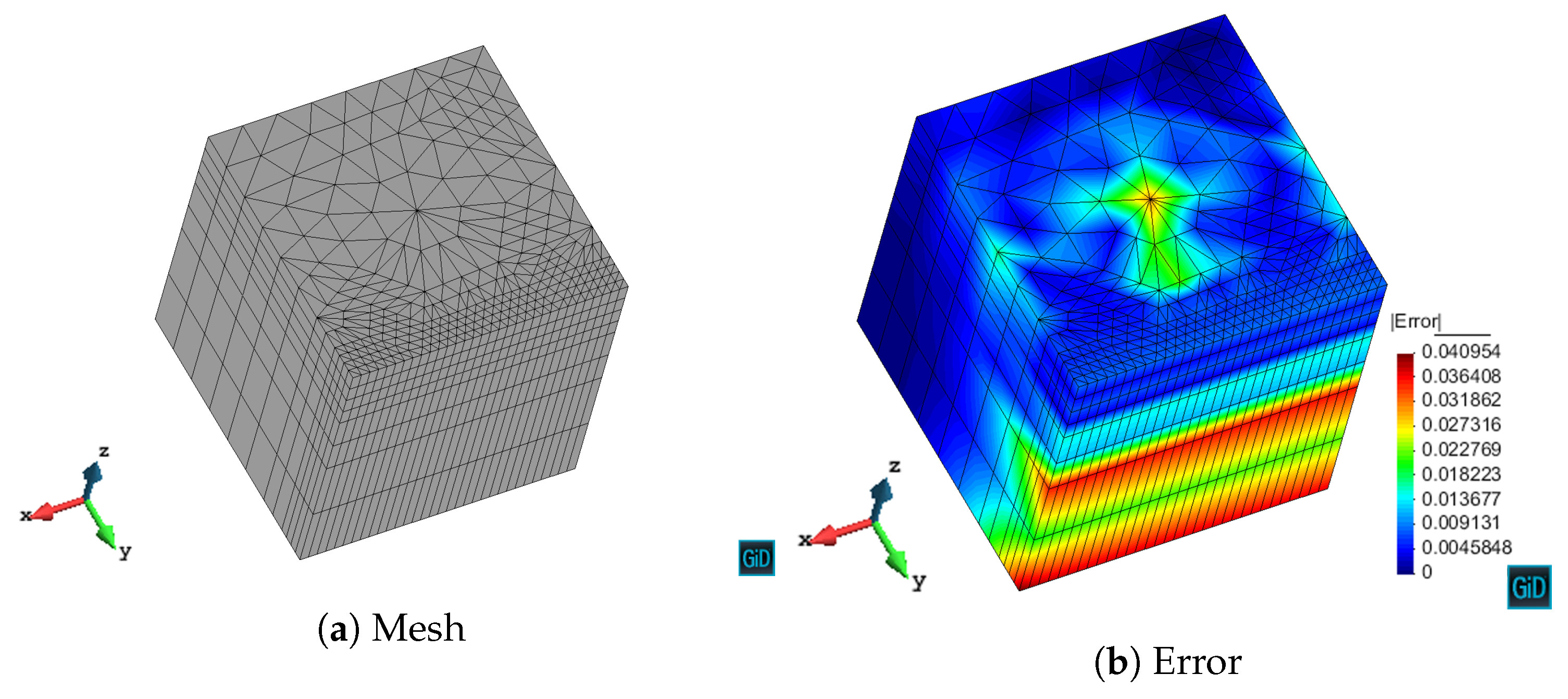
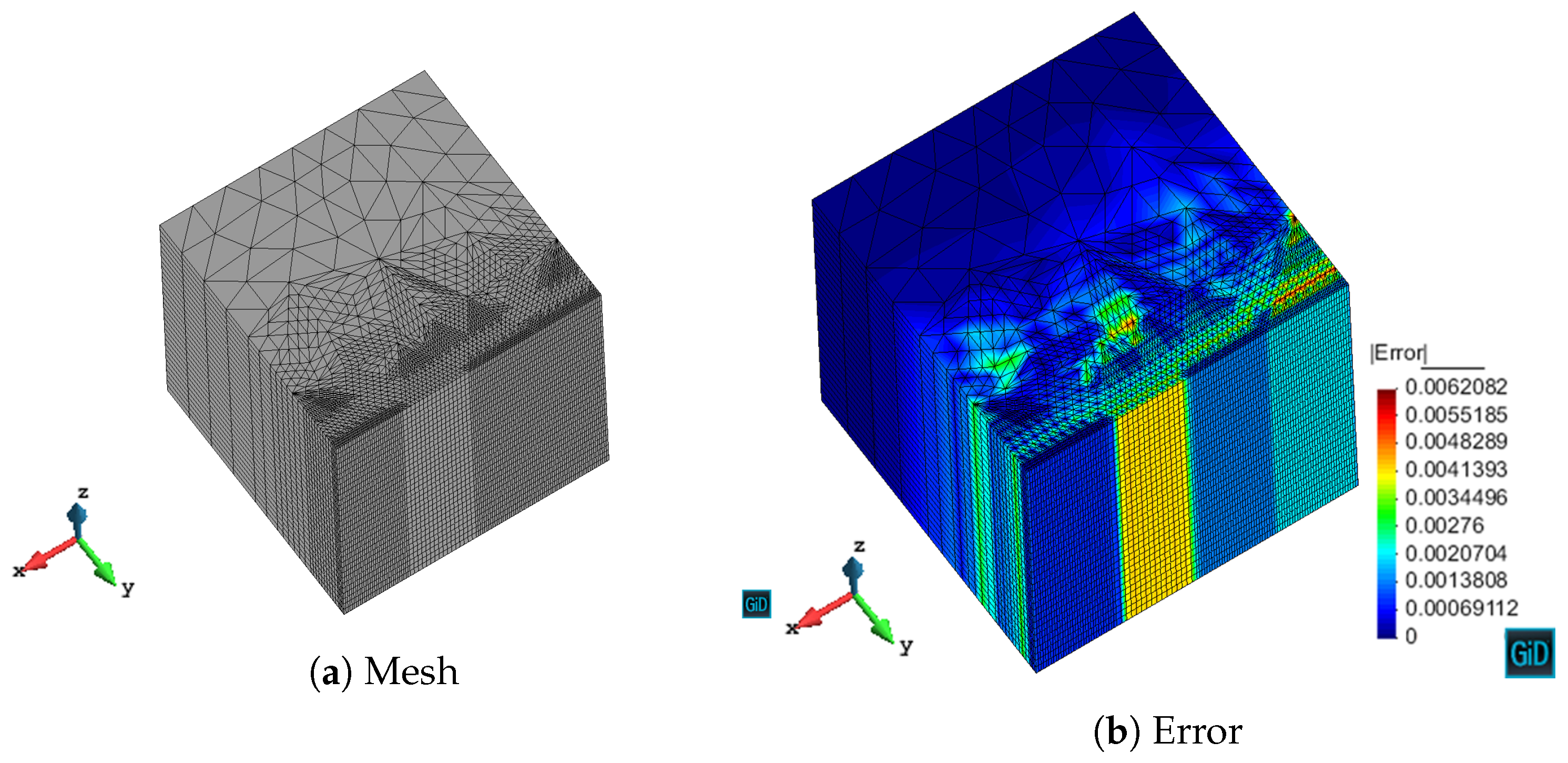
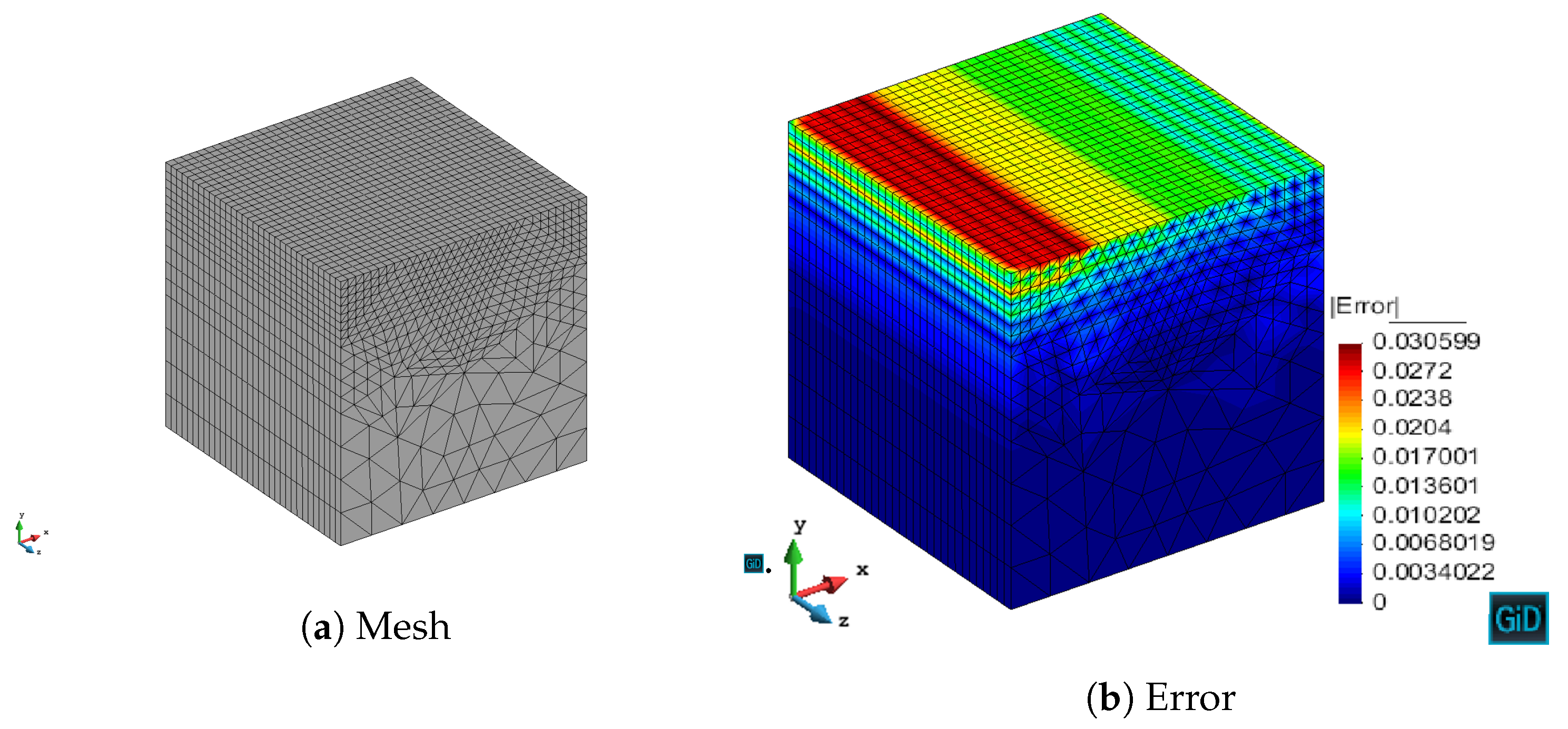
We have validated with numerical results the performance of the algorithm. We have shown the different behavior of each marking strategy: strategies based on the energy of the residual for each element show smaller elements around areas of stronger error, whereas strategies based on a given threshold of the element with maximum error yield more uniform meshes. In contrast, strategies based on refining a given percentage of the elements lead to more irregular meshes. All of the strategies provide smaller elements in higher error areas for both MMS and propagation problems. In addition, we have shown the performance of the algorithm with a singularity due to the geometry of the problem to be solved. This algorithm provides smaller elements in the vicinity of the singularity, as expected giving a better approximation of the singularity with fewer unknowns compared to the uniform refinement.
As future research lines, the treatment of hanging nodes would eliminate the process of conformation, easing the step of refinement. Moreover, we could detect in which direction the estimator is more needed and apply the refinement only in the horizontal or vertical direction as detected.

Author Contributions

Conceptualization, A.A.-M. and L.E.G.-C.; software, A.A.-M.; validation, A.A.-M. and L.E.G.-C.; investigation, A.A.-M. and L.E.G.-C.; data curation, A.A.-M.; writing—original draft preparation, A.A.-M.; writing—review and editing, L.E.G.-C.; supervision, L.E.G.-C.; resources, L.E.G.-C.; funding acquisition, L.E.G.-C. Both authors have read and agreed to the published version of the manuscript.

Funding

This work has been financially supported by TEC2016-80386-P.

Institutional Review Board Statement

Not applicable.

Informed Consent Statement

Not applicable.

Data Availability Statement

The data presented in this study are available on request from the corresponding author.

Conflicts of Interest

The authors declare no conflict of interest.

Abbreviations

The following abbreviations are used in this manuscript:
FEMFinite Element Method
MMSMethod of Manufactured Solutions
SERSolve–Estimate–Refine
2DTwo dimensions

References

  1. Monk, P. Finite Element Methods for Maxwell’s Equations; Oxford University Press: Oxford, UK, 2003. [Google Scholar]
  2. Jin, J.M. The Finite Element Method in Electromagnetics; John Wiley & Sons: Hoboken, NJ, USA, 2015. [Google Scholar]
  3. Salazar-Palma, M.; Sarkar, T.K.; García-Castillo, L.E.; Roy, T.; Djordjevic, A.R. Iterative and Self-Adaptive Finite-Elements in Electromagnetic Modeling; Artech House Publishers, Inc.: Norwood, MA, USA, 1998. [Google Scholar]
  4. Zienkiewicz, O.C.; Taylor, R.L. The Finite Element Method: Solid Mechanics; Butterworth-Heinemann: Oxford, UK, 2000. [Google Scholar]
  5. Guo, B.; Babuška, I. The H-p Version of the Finite Element Method. Comput. Mech. 1986, 1, 21–41. [Google Scholar] [CrossRef] [Green Version]
  6. Demkowicz, L. Computing with Hp-Adaptive Finite Elements: Volume 1 One and Two Dimensional Elliptic and Maxwell Problems; Chapman and Hall/CRC: Boca Raton, FL, USA, 2006. [Google Scholar]
  7. Demkowicz, L.; Kurtz, J.; Pardo, D.; Paszenski, M.; Rachowicz, W.; Zdunek, A. Computing with Hp-ADAPTIVE FINITE ELEMENTS: Volume II Frontiers: Three Dimensional Elliptic and Maxwell Problems with Applications; CRC Press: Boca Raton, FL, USA, 2007. [Google Scholar]
  8. Mitchell, W.F. How High a Degree Is High Enough for High Order Finite Elements? Procedia Comput. Sci. 2015, 51, 246–255. [Google Scholar] [CrossRef] [Green Version]
  9. Graglia, R.D.; Wilton, D.R.; Peterson, A.F.; Gheorma, I. Higher Order Interpolatory Vector Bases on Prism Elements. IEEE Trans. Antennas Propag. 1998, 46, 442–450. [Google Scholar] [CrossRef]
  10. Amor-Martin, A.; Garcia-Castillo, L.E.; Garcia-Donoro, D. Second-Order Nédélec Curl-Conforming Prismatic Element for Computational Electromagnetics. IEEE Trans. Antennas Propag. 2016, 64, 4384–4395. [Google Scholar] [CrossRef]
  11. Solin, P. Adaptive Hp-FEM with Arbitrary-Level Hanging Nodes for Maxwell’s Equations. Adv. Appl. Math. Mech. 2010, 2, 518–532. [Google Scholar] [CrossRef]
  12. Ainsworth, M.; Ma, X. Non-Uniform Order Mixed FEM Approximation: Implementation, Post-Processing, Computable Error Bound and Adaptivity. J. Comput. Phys. 2012, 231, 436–453. [Google Scholar] [CrossRef]
  13. Darrigrand, V.; Pardo, D.; Chaumont-Frelet, T.; Gómez-Revuelto, I.; Garcia-Castillo, L.E. A Painless Automatic Hp-Adaptive Strategy for Elliptic Problems. Finite Elem. Anal. Des. 2020, 178, 103424. [Google Scholar] [CrossRef]
  14. Darrigrand, V.; Rodríguez-Rozas, Á.; Muga, I.; Pardo, D.; Romkes, A.; Prudhomme, S. Goal-Oriented Adaptivity Using Unconventional Error Representations for the Multidimensional Helmholtz Equation. Int. J. Numer. Methods Eng. 2018, 113, 22–42. [Google Scholar] [CrossRef]
  15. Mitchell, W.F.; McClain, M.A. A Comparison of Hp-Adaptive Strategies for Elliptic Partial Differential Equations. ACM Trans. Math. Softw. 2014, 41, 1–39. [Google Scholar] [CrossRef]
  16. Zander, N.; Bog, T.; Kollmannsberger, S.; Schillinger, D.; Rank, E. Multi-Level Hp-Adaptivity: High-Order Mesh Adaptivity without the Difficulties of Constraining Hanging Nodes. Comput. Mech. 2015, 55, 499–517. [Google Scholar] [CrossRef]
  17. Wang, Y.; Bangerth, W.; Ragusa, J. Three-Dimensional h-Adaptivity for the Multigroup Neutron Diffusion Equations. Prog. Nucl. Energy 2009, 51, 543–555. [Google Scholar] [CrossRef]
  18. Nagaraja, S.; Elhaddad, M.; Ambati, M.; Kollmannsberger, S.; De Lorenzis, L.; Rank, E. Phase-Field Modeling of Brittle Fracture with Multi-Level Hp-FEM and the Finite Cell Method. Comput. Mech. 2019, 63, 1283–1300. [Google Scholar] [CrossRef] [Green Version]
  19. Ledger, P.D. Hp-Finite Element Discretisation of the Electrical Impedance Tomography Problem. Comput. Methods Appl. Mech. Eng. 2012, 225–228, 154–176. [Google Scholar] [CrossRef]
  20. Rachowicz, W.; Zdunek, A. Application of the FEM with Adaptivity for Electromagnetic Inverse Medium Scattering Problems. Comput. Methods Appl. Mech. Eng. 2011, 200, 2337–2347. [Google Scholar] [CrossRef]
  21. Li, J.; Huang, Y.; Yang, W. An Adaptive Edge Finite Element Method for Electromagnetic Cloaking Simulation. J. Comput. Phys. 2013, 249, 216–232. [Google Scholar] [CrossRef]
  22. Bériot, H.; Prinn, A.; Gabard, G. Efficient Implementation of High-Order Finite Elements for Helmholtz Problems. Int. J. Numer. Methods Eng. 2016, 106, 213–240. [Google Scholar] [CrossRef] [Green Version]
  23. Wang, H.; Yang, W.; Huang, Y. An Adaptive Edge Finite Element Method for the Maxwell’s Equations in Metamaterials. Electron. Res. Arch. 2020, 28, 961. [Google Scholar] [CrossRef]
  24. Schillinger, D.; Düster, A.; Rank, E. The Hp-d-Adaptive Finite Cell Method for Geometrically Nonlinear Problems of Solid Mechanics. Int. J. Numer. Methods Eng. 2012, 89, 1171–1202. [Google Scholar] [CrossRef]
  25. Bergot, M.; Duruflé, M. High-Order Optimal Edge Elements for Pyramids, Prisms and Hexahedra. J. Comput. Phys. 2013, 232, 189–213. [Google Scholar] [CrossRef] [Green Version]
  26. Carrera, E.; Valvano, S.; Kulikov, G.M. Multilayered Plate Elements with Node-Dependent Kinematics for Electro-Mechanical Problems. Int. J. Smart Nano Mater. 2018, 9, 279–317. [Google Scholar] [CrossRef] [Green Version]
  27. Pagani, A.; Valvano, S.; Carrera, E. Analysis of Laminated Composites and Sandwich Structures by Variable-Kinematic MITC9 Plate Elements. J. Sandw. Struct. Mater. 2018, 20, 4–41. [Google Scholar] [CrossRef] [Green Version]
  28. Chen, D.; Jiao, D. A Direct Domain-Decomposition-Based Time- Domain Finite-Element Method of Linear Complexity for Simulating Multiscaled Structures in Integrated Circuit Systems. IEEE Trans. Antennas Propag. 2012, 60, 5228–5239. [Google Scholar] [CrossRef]
  29. Garcia-Donoro, D.; Ting, S.; Amor-Martin, A.; Garcia-Castillo, L.E. Analysis of Planar Microwave Devices Using Higher Order Curl-Conforming Triangular Prismatic Finite Elements. Microw. Opt. Technol. Lett. 2016, 58, 1794–1801. [Google Scholar] [CrossRef]
  30. Hirayama, E.; Alam, S.; Hayashi, Y.; Koshiba, M. Vector Finite Element Method with Mixed-Interpolation-Type Triangular-Prism Element for Waveguide Discontinuities. IEEE Trans. Microw. Theory Tech. 1994, 42, 2311–2316. [Google Scholar] [CrossRef]
  31. Zboinski, G. Application of the Three-Dimensional Triangular-Prism Hpq Adaptive Finite Element to Plate and Shell Analysis. Comput. Struct. 1997, 65, 497–514. [Google Scholar] [CrossRef]
  32. Meister, O.; Bader, M. 2D Adaptivity for 3D Problems: Parallel SPE10 Reservoir. Simulation on Dynamically Adaptive Prism Grids. J. Comput. Sci. 2015, 9, 101–106. [Google Scholar] [CrossRef]
  33. Garcia-Donoro, D.; Garcia-Castillo, L.E.; Ting, S.W. Verification Process of Finite-Element Method Code for Electromagnetics: Using the Method of Manufactured Solutions. IEEE Antennas Propag. Mag. 2016, 58, 28–38. [Google Scholar] [CrossRef]
  34. Botha, M.M.; Davidson, D.B. An Explicit a Posteriori Error Indicator for Electromagnetic, Finite Element-Boundary Integral Analysis. IEEE Trans. Antennas Propag. 2005, 53, 3717–3725. [Google Scholar] [CrossRef]
  35. Melenk, J.; Wohlmuth, B. On Residual-Based a Posteriori Error Estimation in Hp-FEM. Adv. Comput. Math. 2001, 15, 311–331. [Google Scholar] [CrossRef]
  36. Bürg, M. A Residual-Based a Posteriori Error Estimator for the Hp-Finite Element Method for Maxwell’s Equations. Appl. Numer. Math. 2012, 62, 922–940. [Google Scholar] [CrossRef]
  37. Boffi, D.; Gastaldi, L.; Rodríguez, R.; Šebestová, I. Residual-Based a Posteriori Error Estimation for the Maxwell’s Eigenvalue Problem. IMA J. Numer. Anal. 2017, 37, 1710–1732. [Google Scholar]
  38. Babuvška, I.; Rheinboldt, W.C. Error Estimates for Adaptive Finite Element Computations. SIAM J. Numer. Anal. 1978, 15, 736–754. [Google Scholar] [CrossRef]
  39. Hennig, P.; Kästner, M.; Morgenstern, P.; Peterseim, D. Adaptive Mesh Refinement Strategies in Isogeometric Analysis— A Computational Comparison. Comput. Methods Appl. Mech. Eng. 2017, 316, 424–448. [Google Scholar] [CrossRef] [Green Version]
  40. Verfürth, R. A Posteriori Error Estimation and Adaptive Mesh-Refinement Techniques. J. Comput. Appl. Math. 1994, 50, 67–83. [Google Scholar] [CrossRef]
  41. Dörfler, W.; Heuveline, V. Convergence of an Adaptive Hp Finite Element Strategy in One Space Dimension. Appl. Numer. Math. 2007, 57, 1108–1124. [Google Scholar] [CrossRef]
  42. Dörfler, W. A Convergent Adaptive Algorithm for Poisson’s Equation. SIAM J. Numer. Anal. 1996, 33, 1106–1124. [Google Scholar] [CrossRef]
  43. Bank, R.E.; Sherman, A.H.; Weiser, A. Some Refinement Algorithms and Data Structures for Regular Local Mesh Refinement. Sci. Comput. Appl. Math. Comput. Phys. Sci. 1983, 1, 3–17. [Google Scholar]
  44. Schneider, T.; Hu, Y.; Dumas, J.; Gao, X.; Panozzo, D.; Zorin, D. Decoupling Simulation Accuracy from Mesh Quality. ACM Trans. Graph. 2018, 37, 1–14. [Google Scholar] [CrossRef]
Figure 1. Each possible refinement for triangular prisms. We show for brevity one case out of three for 10 and 11 cases.
Applsci 11 03683 g001
Figure 2. An example of application of conformation process in refined meshes.
Applsci 11 03683 g002
Figure 3. Presence of anomaly (eye) in the refined mesh.
Applsci 11 03683 g003
Figure 4. Treatment of eyes in the refined mesh.
Applsci 11 03683 g004
Figure 5. Presence of distorted elements in the refined mesh.
Applsci 11 03683 g005
Figure 6. Refinement with a criterion for not allowing elements with an angle lower than 0.4 rad.
Applsci 11 03683 g006
Figure 7. Refinement with criteria for not allowing neither eyes nor elements with an angle lower than 0.4 rad.
Applsci 11 03683 g007
Figure 8. Convergence of the maximum value of the error for (13).
Applsci 11 03683 g008
Figure 9. Approximation of (13) using the next-step marking strategy.
Applsci 11 03683 g009
Figure 10. Approximation of (13) using the quantile marking strategy.
Applsci 11 03683 g010
Figure 11. Approximation of (13) using the maximum marking strategy.
Applsci 11 03683 g011
Figure 12. Approximation of (13) using the fixed-energy marking strategy.
Applsci 11 03683 g012
Figure 13. Approximation of (13) using the SER marking strategy.
Applsci 11 03683 g013
Figure 14. First iteration for a structured mesh of a WR-90 waveguide.
Applsci 11 03683 g014
Figure 15. Second iteration for a structured mesh of a WR-90 waveguide.
Applsci 11 03683 g015
Figure 16. Third iteration for a structured mesh of a WR-90 waveguide.
Applsci 11 03683 g016
Figure 17. WR-90 bend waveguide used in Section 3.3.
Applsci 11 03683 g017
Figure 18. First iteration for L-shaped problem with h adaptivity.
Applsci 11 03683 g018
Figure 19. Second iteration for L-shaped problem with h adaptivity.
Applsci 11 03683 g019
Figure 20. Third iteration for L-shaped problem with h adaptivity.
Applsci 11 03683 g020
Figure 21. Evolution of the electric field for h refinement in a L-shaped domain.
Applsci 11 03683 g021
Figure 22. Evolution of the electric field for uniform refinement in an L-shaped domain.
Applsci 11 03683 g022
Figure 23. Representation of the singularity with different levels of h refinement.
Applsci 11 03683 g023
Table 1. θ parameter for verification with MMS.
E MMS y 9
Quantile0.3
Maximum0.05
Fixed-Energy0.9999
SER0.9
Publisher’s Note: MDPI stays neutral with regard to jurisdictional claims in published maps and institutional affiliations.

