Article

Wideband-Narrowband Switchable Tapered Slot Antenna for Breast Cancer Diagnosis and Treatment

The Electrical and Electronic Engineering Department, Yonsei University, Seoul 03722, Korea
*
Author to whom correspondence should be addressed.
Appl. Sci. 2021, 11(8), 3606; https://doi.org/10.3390/app11083606
Submission received: 17 March 2021 / Revised: 13 April 2021 / Accepted: 15 April 2021 / Published: 16 April 2021

Abstract

:
In this paper, a wideband-narrowband switchable tapered slot antenna (TSA) with a compact meander line resonator for an integrated microwave imaging and hyperthermia system was proposed. A compact meander line resonator, which exhibited band-pass characteristics and provided narrowband characteristics by using one PIN diode, was fabricated beneath the tapered slot of the wideband TSA to minimize the degradation of the wideband characteristics. Moreover, the electromagnetic energy was transferred to the meander line resonator with a coupling effect to ensure effective frequency switching. By adapting a PIN diode on the meander line resonator, frequency switching could be achieved. In this way, the proposed antenna could operate in a real-time frequency switching mode between the ultra-wideband (UWB; 3.1~10 GHz), which is used for microwave imaging, and the 2.45 GHz band (industrial, scientific, and medical, ISM band), which is used for microwave hyperthermia. Frequency and time-domain results proved the applicability of the proposed antenna to an integrated breast cancer detection and treatment system.

1. Introduction

Breast cancer treatments are being developed rapidly to reduce the dangerous radiation associated with conventional methods [1]. The early detection of breast cancer has received significant attention among research groups, and common techniques are based on X-rays, magnetic resonance imaging (MRI), and computer tomography (CT) [2]. However, these techniques have numerous drawbacks such as ionizing radiation, high cost, health risks, and so on. Radar-based microwave imaging is an effective tumor detection method. In this method, malignant tissues within the breast can be detected because of significant differences in the dielectric properties between normal breast cells and tumor cells. These images can be produced by employing ultra-wideband (UWB) antennas [3,4,5,6,7]. These antennas transmit and receive short-duration pulses and detect the scattered signal differences between normal and malignant tissues.
The surgical operation, radiotherapy, chemotherapy, and hyperthermia are the main methods to treat breast cancer. Among these, a microwave hyperthermia system for cancer treatment is reliable, non-invasive, cost-effective, and painless in comparison to surgical operations. Furthermore, hyperthermia has a synergistic effect when used in combination with radiation oncology or chemotherapy. Non-invasive hyperthermia, which employs a microwave antenna, is a reliable treatment method to achieve effective breast tumor necrosis [8]. In this method, electromagnetic energy (EM) is radiated from a narrowband antenna and concentrated on the tumor region, where heating is applied as a therapeutic treatment [9,10,11].
However, as the microwave diagnosis system operates separately from the treatment system, the process is complicated, time-consuming, and expensive. The integration of these two systems simplifies the process and provides a comfortable treatment environment for patients. To implement such an integrated system, the characteristics of the two different systems must be incorporated into a single antenna. However, as the allocated wideband frequency for microwave imaging and narrowband frequency for hyperthermia are different, frequency reconfigurable characteristic is essential for the antenna. Frequency reconfigurable antennas have been investigated widely in terms of switching the wide- to narrowband with PIN diode switch. The research of wideband to narrowband switching antennas was presented over past years [12,13,14,15,16,17]. In [12], the ring slot resonators were perturbed in the antenna feed line with PIN diodes. In [13,14], the frequency notched and narrowband characteristics were realized by applying the ring slots and split ring resonators (SRR) in the feeding area. In [15,16], the C-, T-shaped slots and ring slots were notched on the flared slot of a tapered slot antenna (TSA) for wide to multiband switching. In [17], the C-slot patch antenna was designed on the dual patch element in order to achieve reconfigurability. In these papers, however, as the narrowband structures for frequency switching were inserted directly on the antenna surface or feeding area of the wideband antenna, the wideband performances of the antenna degraded, and the design complexity increased because at least two PIN diodes were used to obtain frequency switching and wideband characteristics. Furthermore, the narrowband structure must be compact in size to minimize interference with the wideband antenna. However, existing narrowband structures are electrically large because of the resonance length of their operating frequencies.
In this paper, a wideband to a narrowband switchable antenna with a compact meander line resonator was proposed for an integrated microwave imaging and hyperthermia system for breast cancer detection and treatment. The conventional wideband TSA is designed to operate in the 3.1–10 GHz (UWB) frequency band for microwave imaging. The narrowband operation for hyperthermia can be achieved with meander line resonators with a PIN diode switch. In the proposed structure, the frequency switching mechanism was simplified by using one PIN diode. To minimize the degradation of the wideband characteristic of conventional TSA, the meander line resonator was designed to be compact on the back layer of the TSA. Furthermore, as the electromagnetic energy was transferred from the tapered slot of the TSA to the meander line resonator in the back layer with a coupling effect, effective frequency switching was made possible. The frequency and time-domain performance of the proposed antenna were discussed to demonstrate its applicability as a real-time breast cancer detection and treatment system.

2. Design of the Proposed Frequency Switchable Tapered Slot Antenna

The configuration of the proposed system is presented in Figure 1. The system consisted of an external microwave radiator with an artificial cylindrical breast phantom. All simulation and experimental results were based on the configuration of Figure 1. To verify the electromagnetic effects of the proposed antenna on the human body, an artificial breast phantom was formed with homogeneous material that takes into account the fatty component ( ε r = 5.14, σ = 0.137 S/m) of the human breast [18]. The external radiator was in direct contact with the breast phantom to achieve maximum electromagnetic wave transmission.

2.1. Design of the Wideband Tapered Slot Antenna

The conventional wideband TSA, which is suitable for a microwave imaging system, is shown in Figure 2. The conventional TSA was printed on an 0.8-mm-thick FR-4 substrate ( ε r = 4.3, tan δ = 0.025) over an area of 80 mm × 40 mm. In order to reduce the reflection of the electric field at the boundary between the proposed antenna and breast phantom, the FR-4 substrate was chosen because the dielectric constant of the substrate is similar to the dielectric constant of the breast phantom.
The exponential slot is guided by the following equation;
Y = C 1 e R x + C 2 ,   C 1 = y 2 y 1 e R x 2 e R x 1 ,   C 2 = e R x 2 y 1 e R x 1 y 2 e R x 2 e R x 1  
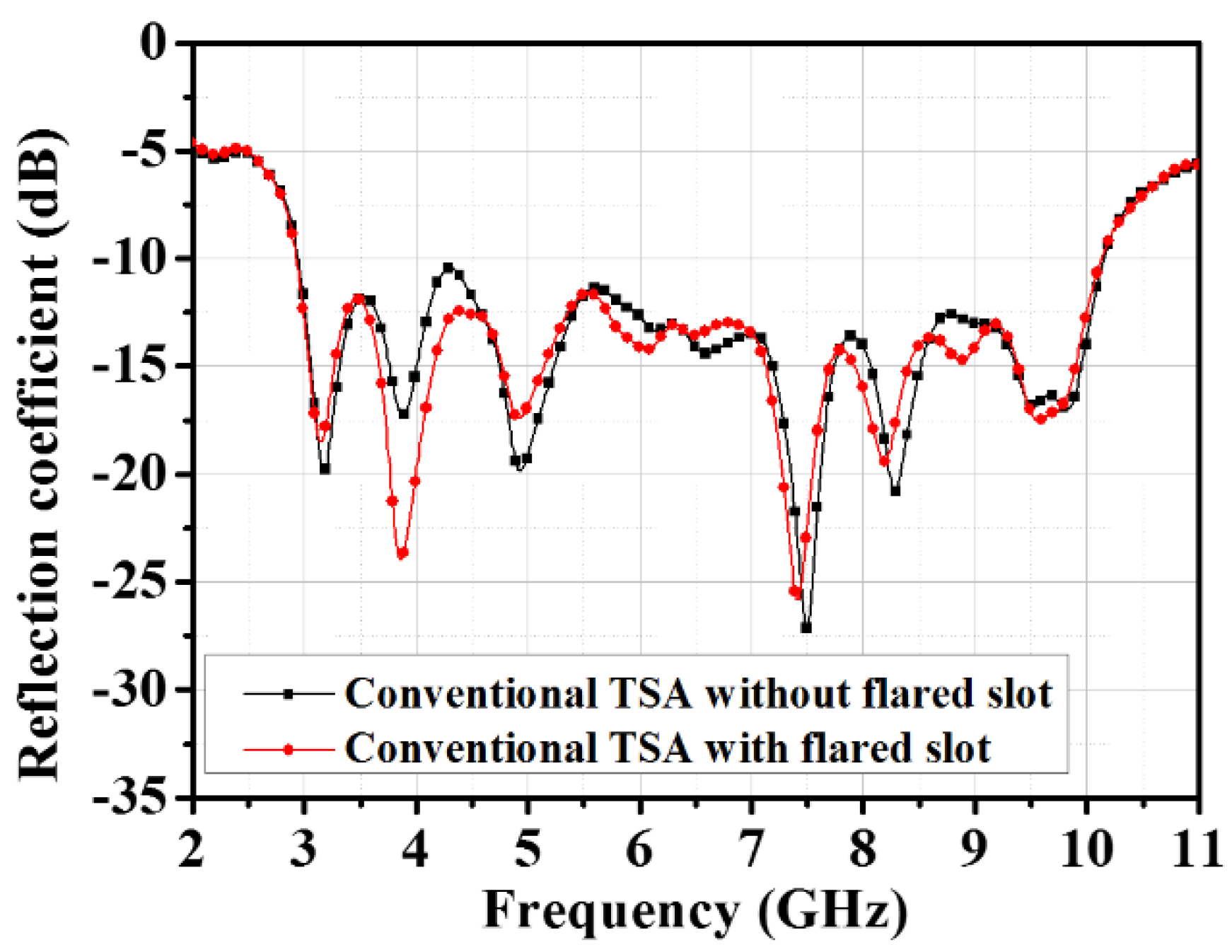
where R is the exponential rate and x 1 ,   x 2 ,   y 1 , and y 2 indicate the start- and endpoints of the slotline [19]. A microstrip-to-slotline transition technique was applied to achieve stable wideband characteristics [20,21]. To achieve a wideband transition, the microstrip-radial-open stub and slotline-round-short stub present virtual short and open circuits, respectively. The designed antenna interacted with the high dielectric human breast, so impedance characteristics had to be enhanced in order to maximize power transformation. Therefore, we designed flared slots to enhance the reflection coefficient in 3.5–5 GHz. The flared slots were designed near the input aperture of the tapered slot, where the current flow was strong, for effective input impedance control. The step impedance can be changed by controlling the exponential rate of the flared slots. After fine-tuning, the impedance matching characteristic was partially enhanced in the 3.5–5 GHz, as shown in Figure 3. A full-wave simulation was performed with Microwave Studio of Computer Simulation Technology (CST). As a result, the proposed TSA achieved optimal wideband operation in the 3.1–10 GHz.

2.2. Design of the Narrowband Resonator

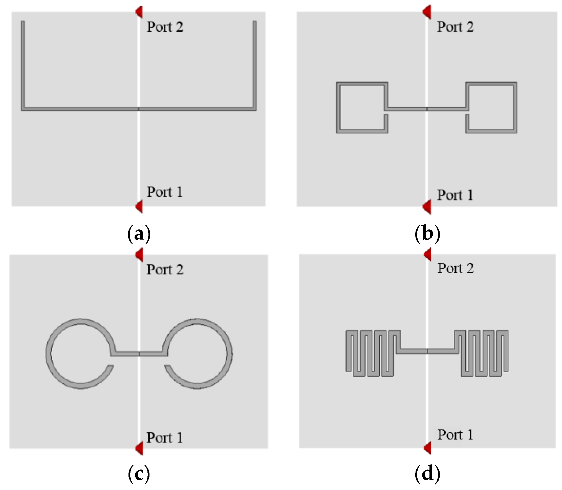
The narrowband characteristic in wideband TSA can be achieved by inducing current to the narrowband resonator in the back layer of the TSA. Figure 4a–d shows the typical shapes for frequency switching; bent dipole, square ring, round ring, and meander line. In terms of losses and size, the narrowband resonator must have low losses and be small in size. To verify the resonator characteristics, a radio frequency (RF) signal was induced between the vertical slot on the ground plane, and the coupling energy was induced to the resonator on the top layer. Table 1 shows the results for the simulated insertion loss (S21) and the size of resonators, respectively. The S21 results were similar but slightly lower for the round ring and meander line. Moreover, the size of the meander line resonator was smaller than the other shapes. Therefore, we selected the meander line as a narrowband resonator, which was suitable for electrically small antennas with closely coupled element shapes [22].
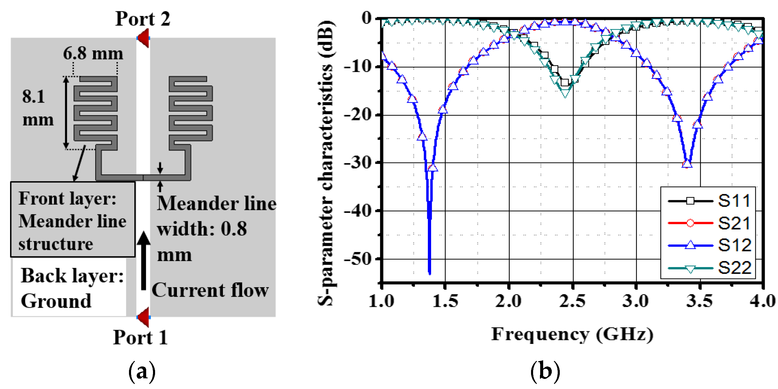
The frequency response of the meander line structure is defined by the width, the number of turns, and the gap size of the meander line, which can be represented by an equivalent lumped circuit model [23,24]. In Figure 5a, the meander line resonator, which was designed on the back of the slotline, induces a coupling current to achieve band-pass characteristics at 2.45 GHz. The meander line resonator is represented by the LC equivalent sub-circuit and will be discussed later.
The meander line structure was based on the cascade connection of several individual line segments. The equivalent lumped circuit of the transmission line segments could be calculated using the T-equivalent network from the equations provided by [23] to reasonably approximate relative changes in the resonant frequency. Changes in the narrowband resonance in terms of the number of turns of the meander line and line length are represented in Figure 6a and b, respectively. For the proposed antenna, both a compact size of 6.8 mm × 8.1 mm (0.11 λ r × 0.13 λ r ) and band-pass filter operation could be achieved by adopting the meander line structure, the S-parameter results of which are shown in Figure 5b, which verified the band-pass operation at 2.45 GHz.

2.3. Frequency Switchable Tapered Slot Antenna with Meander Line Resonator

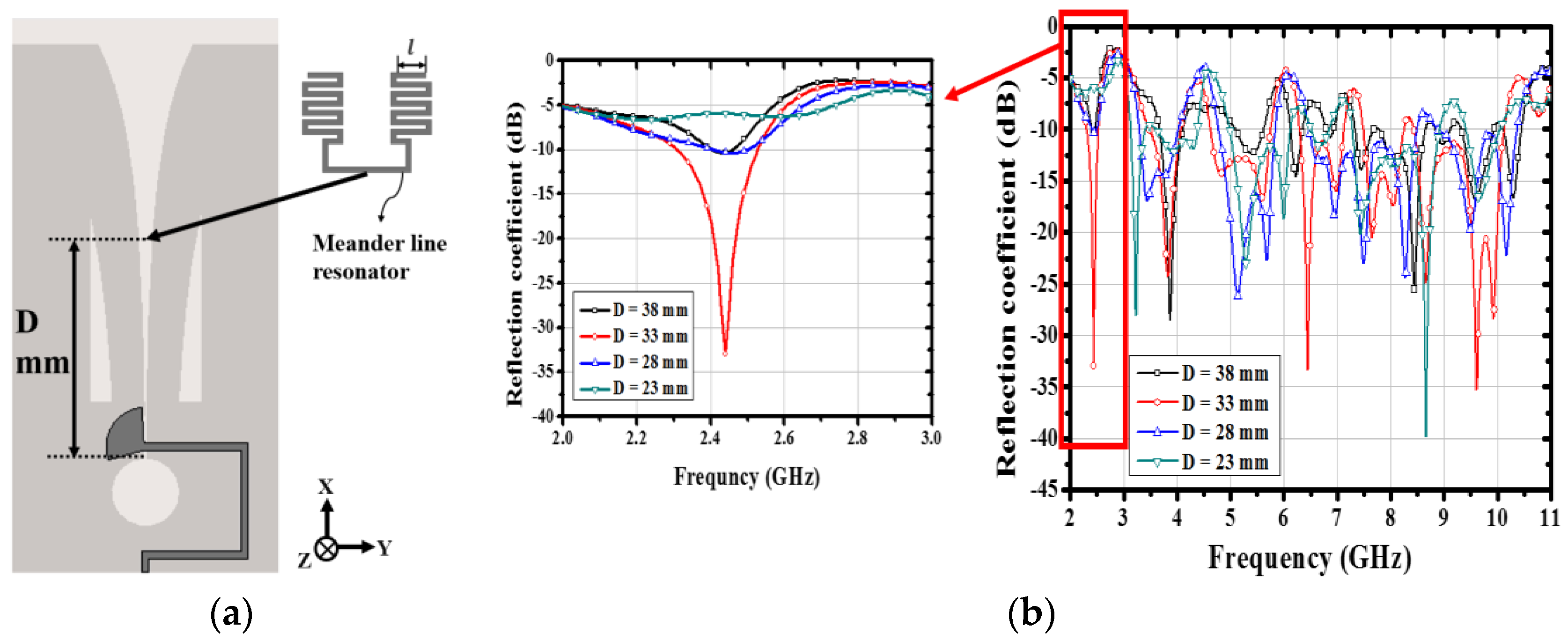
To design the frequency switchable antenna, a meander line resonator was printed on the back layer of the wideband antenna, as shown in Figure 7a. The middle point of the symmetric meander line resonator was placed at a point corresponding to the middle of the flared slot. When the current flows alongside the flared slot, an E-field is formed between the two plates of the slot, and EM energy is transferred to the meander line resonator. The combined equivalent circuit model of the TSA and meander line resonator is shown in Figure 8.
The flared slot of the TSA has various frequency responses that depend on position D of the meander line resonator. The higher band operation is related to the narrow end of the flared slot, whereas the lower band operation is related to the wide end of the flared slot. Therefore, the proposed antenna achieved optimal frequency switchable characteristics by placing a meander line resonator at the optimal point to compensate for the reactance component. The maximum reactance compensation is related to the impedance matching characteristics of the TSA at 2.45 GHz, which is the resonant frequency of the meander line resonator. Changes in the reflection coefficient for different positions of the meander line resonator in the narrowband mode are presented in Figure 7b. It can be observed that for D = 33 mm, the image impedance of the meander transmission line Z T L is matched to the characteristic impedance of the slotline Z S L O T . As a result, the maximum EM energy transfer between the flared slot and the meander line resonator occurred, and the conventional traveling-wave mode changed to the resonance mode in the meander line resonator.

3. Simulation and Measurement Results

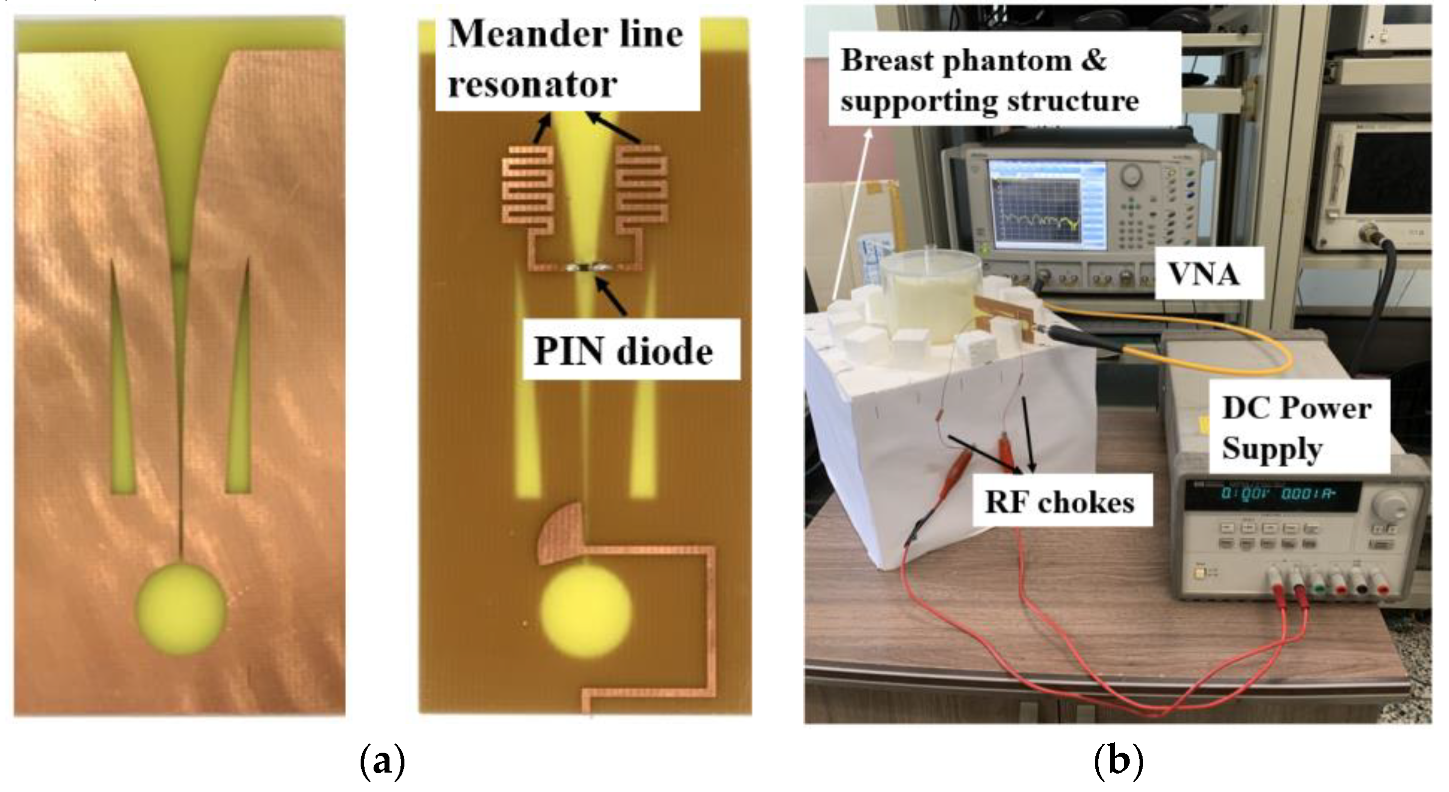
As mentioned earlier, a meander line resonator was printed on the backside of the TSA. To achieve frequency switchable characteristics, an SMV 1231 PIN diode switch was inserted in the middle of the meander line resonator to control the current induced by the flared slot, as shown in Figure 9a. In Figure 9b, the measurement configuration with a fabricated breast phantom and supporting structure is represented. The DC biasing line was connected to the DC power supply through the inductors for RF choking, and the bias voltage was 0.8 V in order to activate the diode.
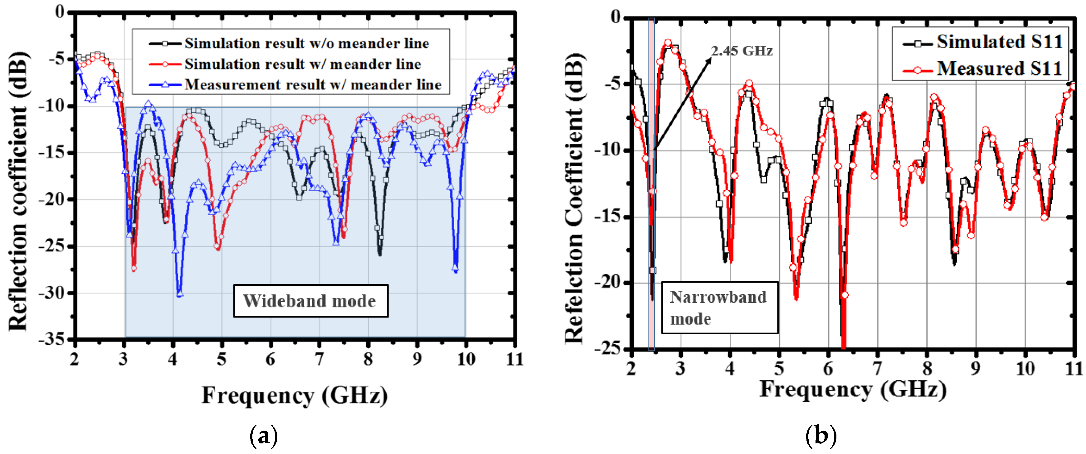
When the PIN diode was in the OFF state, the transmission line that connected the two sides of the symmetric meander line resonator was terminated, and the current was not induced. In this case, the proposed antenna operated as a conventional wideband antenna in the frequency range of 3.1–10 GHz, as shown in Figure 10a. The simulated reflection coefficients both with and without the meander line were compared to verify that the designed meander lines did not degrade the wideband impedance matching characteristic. There were mismatches for the reflection coefficient between the simulated and measured results around 4 and 6.5 GHz. It could be seen that there were some deviations in the measurement condition, such as antenna fabrication errors, coaxial cable utilization in the experiment, soldering effects, and the variation of dielectric properties of the RF-4 substrate within tolerance levels. However, the measured reflection coefficient was acceptable for the entire frequency band.
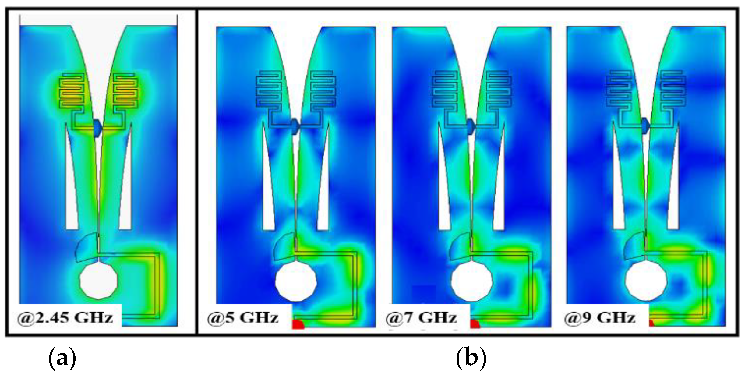
On the other hand, when the PIN diode was in the ON state, the EM energy was transferred to the transmission line between the meander lines and the current induced in the meander line resonators. In this case, the TSA operated as a narrowband antenna, as shown in Figure 10b. In Figure 10b, several resonances are shown in other frequency bands caused by the harmonics of the meander line. Therefore, multiple resonances occurred even in the narrowband mode because of the band-pass characteristic of meander line resonators. However, in this paper, for microwave hyperthermia we only used 2.45 GHz as a power source. Current distributions are presented in Figure 11, verifying the resonance and traveling-wave modes, both of which depended on the PIN diode. Table 2 compares the proposed antenna with the existing research in terms of the type and size of the wideband antenna, the number of switching elements, and the shape and size of the narrowband structure. To compare the electrical size of the narrowband structure with other papers, the resonance frequency and relative dielectric constant of the substrate were considered to calculate the size of the narrowband structure in λ r . The results suggested that the proposed antenna exhibits a frequency switching characteristic with the smallest number of PIN diodes as well as the smallest electrical size for the narrowband structure.
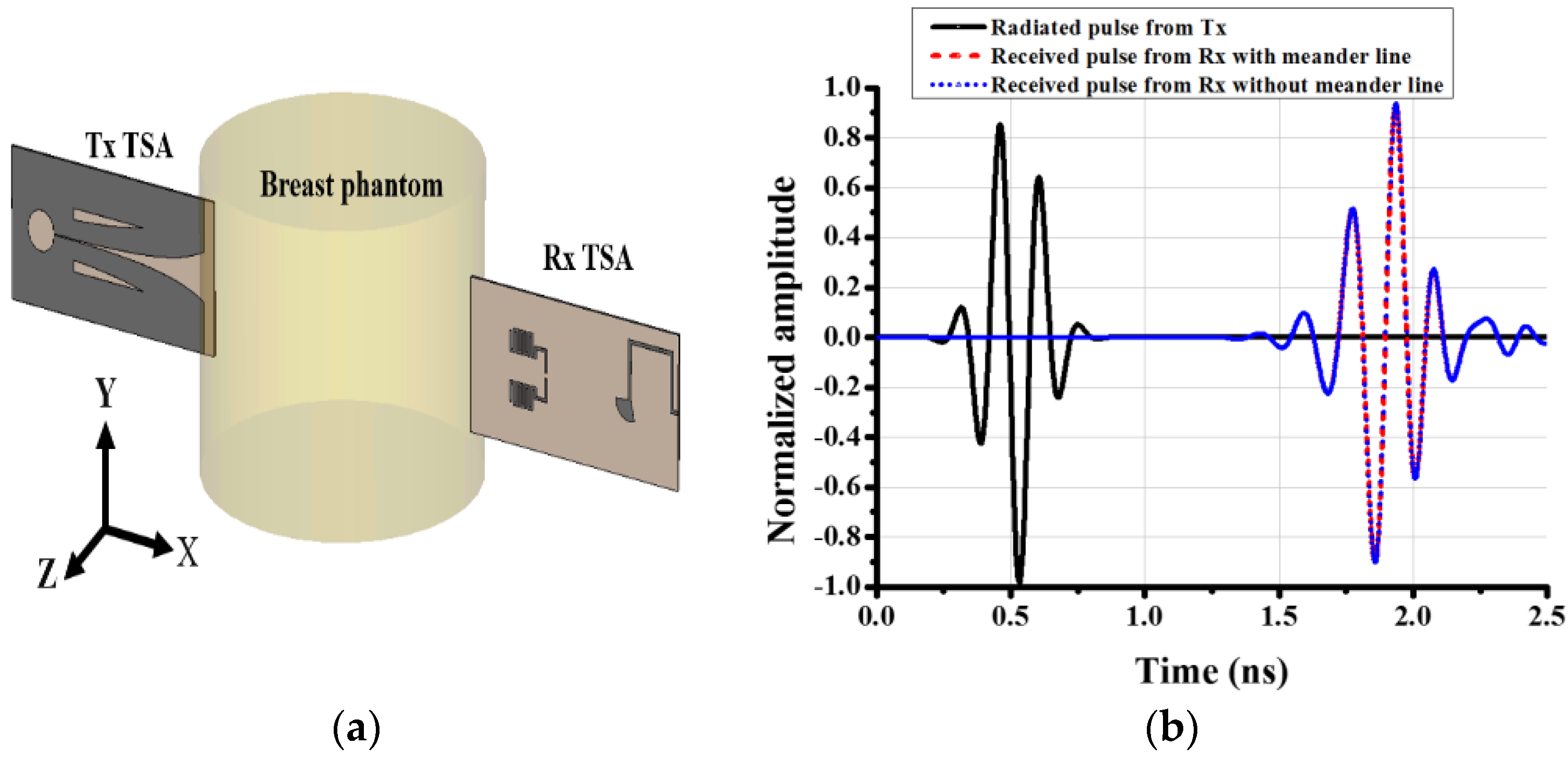
To verify the radiation characteristics of the proposed antenna in the breast phantom for a microwave imaging system, time-domain results were analyzed. In a microwave UWB radar-based imaging system, high-quality image reconstruction can be achieved when the antennas transmit and receive short-duration microwave pulses through a lossy material. In this process, a radiated pulse from the transmitting antenna passes through the breast phantom with low distortion and high efficiency. The Tx and Rx TSAs face each other through the phantom diameter (100 mm), as shown in Figure 12a. The radiated and received pulses both with and without the meander line resonator are shown in Figure 12b. By comparing the shapes between the transmitted and received pulses, it was evident that the proposed TSA exhibited low-pulse distortion characteristics, and the meander line resonator did not affect the pulse characteristic.
A figure of merit for the transmitted and received signal was the fidelity factor (F), which is defined as the maximum magnitude of the cross-correlation between the observed signal at a certain distance and the excitation signal [3]:
r ^ t = r t r t 2 d t 1 / 2   and   f ^ t = f t f t 2 d t 1 / 2
Equation (2) means the signals which are normalized to have unit energy where f(t) is the transmitted signal at the antenna terminal, and r(t) is the received E-field in the time domain.
F = m a x τ f ^ t r ^ t + τ d t
The fidelity factor, F, is represented in Equation (3), which is determined by the peak of the cross-correlation function of the signals. The fidelity factor has a value between 0 and 1. Especially for microwave systems, the fidelity factor value must be over 0.5 [3]. The calculated fidelity factor for the proposed TSA was 0.95. This was a reliable result, which confirmed the suitability of the proposed TSA for microwave imaging systems.
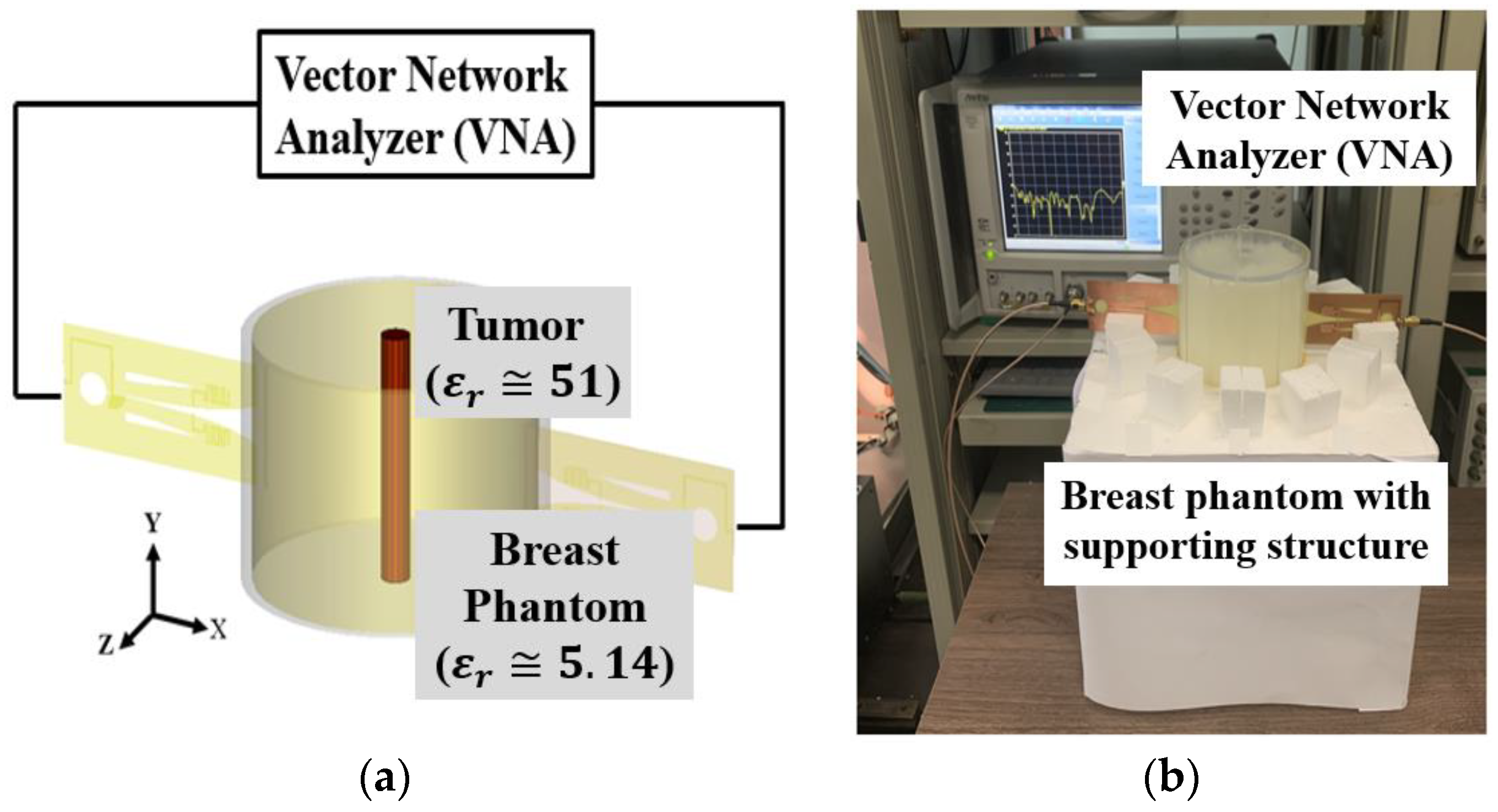
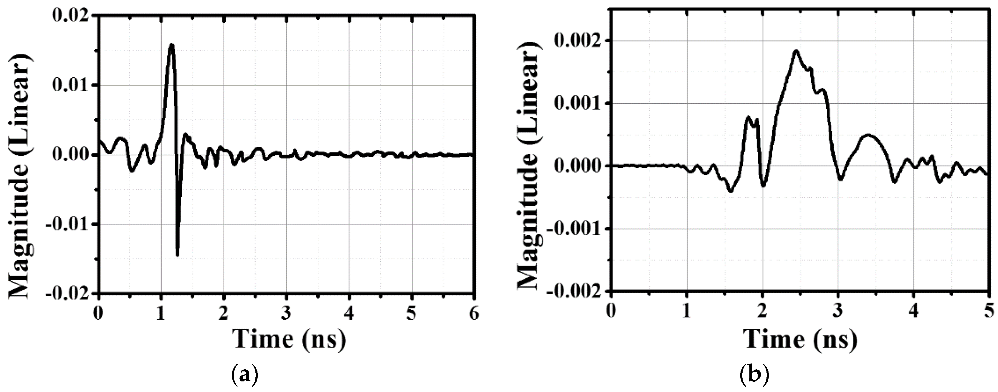
The experimental setup for the time-domain signal acquisition is presented in Figure 13. The dielectric permittivity of a breast cancer cell is almost 10 times larger than the dielectric permittivity of a normal breast cell [18]. A cylindrical cancer cell in the middle of the breast phantom is presented in Figure 13a, the radius of which is 5 mm. As a result of the difference between the dielectric permittivities, a scattering effect occurred when the E-field passed through the breast phantom. The differences of the backscattered time-domain signals, which were measured both with and without a cancer cell, are presented in Figure 14 for reflected and transmitted signals. The UWB signal was radiated using a stepped frequency sweep, and the backscattered signals reflected from the tumor were collected by the receiving antennas at different locations. For each position, the recorded signals from the tumor reflection could be extracted from the overall signal by subtracting the original signal. The collected, scattered signals were converted to the time domain signal by the inverse Fourier transform and applied to an imaging algorithm developed by [7]. When the transmitted signal progresses over time, the skin reflection was identical in both cases.
Therefore, the scattered signals between the tumor cell and homogeneous breast phantom were recorded by the receiving antennas, and these signals were used to infer the existence and location of the arbitrary target. The detected signal differences shown in Figure 14 could be calculated and applied to the UWB multi-static radar-based microwave imaging system to define the tumor cells.
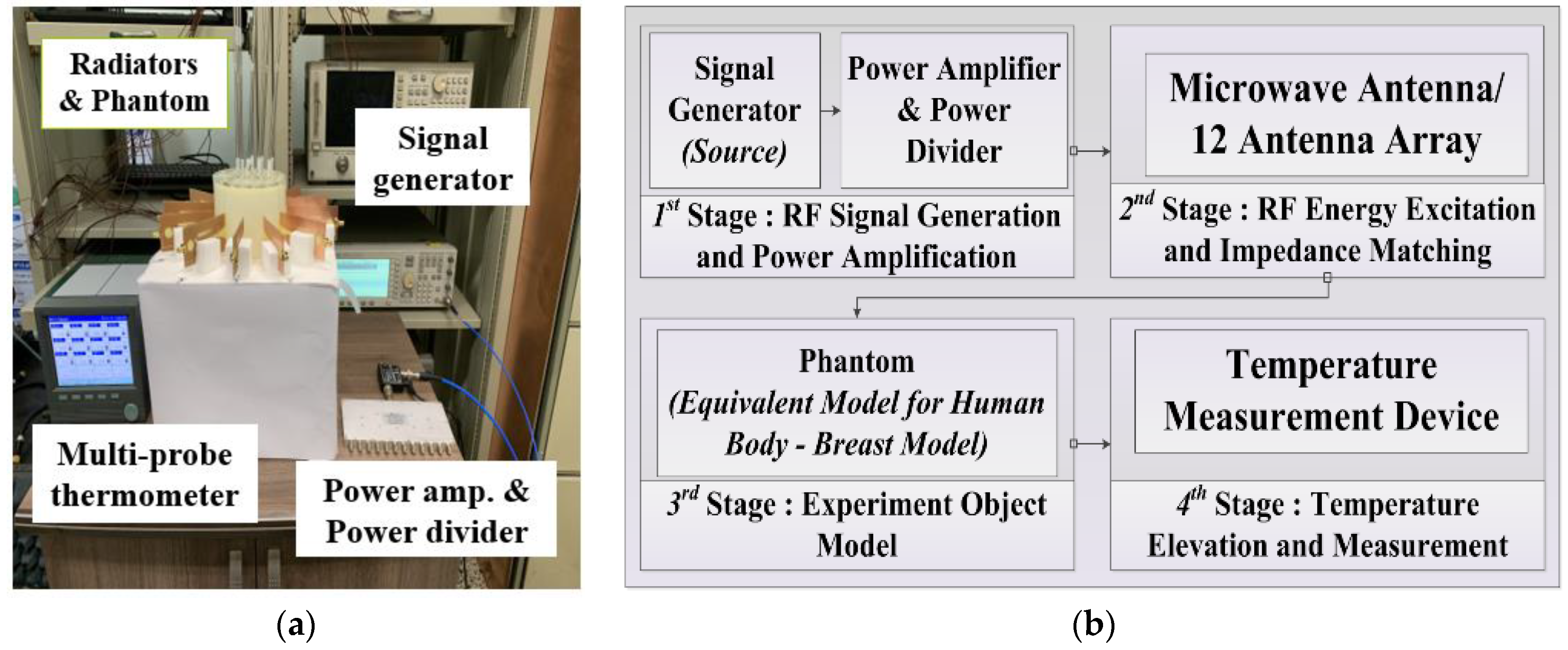
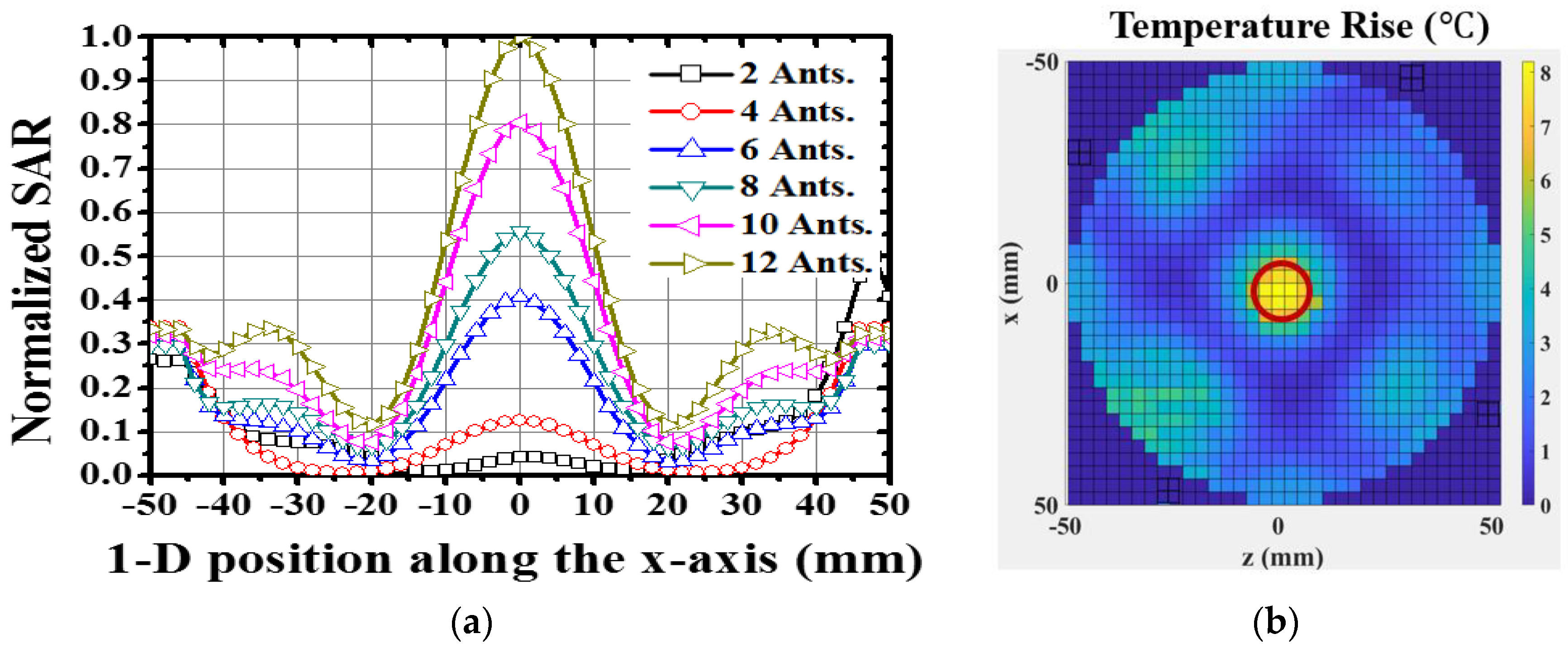
To operate as a hyperthermia system, Figure 15 shows the required configuration of the temperature measurement setup, block diagram of the temperature measuring system (which was composed of the RF signal generation and amplification, as well as RF power division and excitation), and the temperature observation [9,10]. The proposed antenna must exhibit equal polarization characteristics to achieve an effective E-field synthesis in the target area. For hyperthermia application, the specific absorption rate (SAR), which is proportional to the square root of the E-field, is analyzed to verify the radiation characteristics in the breast phantom [9]. In Figure 16a, the variation of the normalized SAR with the number of antennas is presented to verify the EM energy concentration at the center of the breast phantom (x = 0 mm), from which it was evident that the SAR increases by increasing the number of antennas to the target position. To verify the thermal effect for tumor necrosis, the effective treatment area (ETA) was defined [9]. The ETA was regarded as a region in which the tumor satisfied the thermal requirement of the temperature rise, 7–10 °C. The temperature increase measured inside the breast phantom, heated by a 12-array antenna for 1 h, is shown in Figure 16b. The red circular region signifies the ETA, which covers the tumor size.

4. Discussion

In this paper, a frequency switchable tapered slot antenna with a meander line resonator was proposed. The wideband TSA operates in the UWB (3.1–10 GHz) for microwave imaging. A compact meander line resonator with band-pass characteristics was designed and printed on the back of the TSA to minimize the degradation of the wideband characteristic and the additional frequency response at 2.45 GHz for hyperthermia. By positioning the meander line beneath the flared slot, which was propagating the area of TSA, the maximum EM energy transfer between the flared slotline and the meander line resonator was achieved. Frequency switchable characteristics were made possible because of a PIN diode switch. Simulated and measured results demonstrated that the proposed TSA operated selectively in different modes at two different frequency bands. For hyperthermia, the designed antenna exhibited effective EM energy concentration with a thermal treatment effect. The time-domain analysis was also conducted to demonstrate the antenna’s microwave imaging capability. Consequentially, the proposed TSA was expected to be useful in the integrated biomedical system.

Author Contributions

Data curation and writing—original draft preparation, S.L.; writing—review and editing, S.L. and Y.J.Y.; supervision, Y.J.Y. All authors have read and agreed to the published version of the manuscript.

Funding

This research received no external funding.

Institutional Review Board Statement

Not applicable.

Informed Consent Statement

Not applicable.

Data Availability Statement

The data presented in this study are available on request from the corresponding author. The data are not publicly available due to privacy restrictions.

Acknowledgments

This paper was supported by the National Research Foundation of Korea (NRF) grant funded by the Korea government (MSIT) (No. NRF-2019R1A2C1005764).

Conflicts of Interest

The authors declare no conflict of interest.

References

  1. American Cancer Society. Cancer Facts & Figures 2014; American Cancer Society: Atlanta, GA, USA, 2014. [Google Scholar]
  2. Liu, Q.H.; Zhang, Z.Q.; Wang, T.T.; Bryan, J.A.; Ybarra, G.A.; Nolte, L.W.; Joines, W.T. Active Microwave Imaging. I. 2-D Forward and Inverse Scattering Methods. IEEE Trans. Microw. Theory 2002, 50, 123–133. [Google Scholar]
  3. Islam, M.; Islam, M.T.; Samsuzzaman, M.; Faruque, M.R.I.; Misran, N.; Mansor, M.F. A miniaturized antenna with negative index metamaterial based on modified SRR and CLS unit cell for UWB microwave imaging applications. Materials 2015, 8, 392–407. [Google Scholar] [CrossRef] [PubMed]
  4. Bahramiabarghouei, H.; Porter, E.; Santorelli, A.; Gosselin, B.; Popović, M.; Rusch, L.A. Flexible 16 antenna array for microwave breast cancer detection. IEEE Trans. Biomed. Eng. 2015, 62, 2516–2525. [Google Scholar] [CrossRef] [PubMed]
  5. Abbosh, A.; Crozier, S. Strain imaging of the breast by compression microwave imaging. IEEE Antennas Wirel. Propag. Lett. 2010, 9, 1229–1232. [Google Scholar] [CrossRef]
  6. Bourqui, J.; Okoniewski, M.; Fear, E.C. Balanced antipodal Vivaldi antenna with dielectric director for near-field microwave imaging. IEEE Trans. Propag. 2010, 58, 2318–2326. [Google Scholar] [CrossRef]
  7. Islam, M.T.; Mahmud, M.Z.; Islam, M.T.; Kibria, S.; Samsuzzaman, M. A low cost and portable microwave imaging system for breast tumor detection using UWB directional antenna array. Sci. Rep. 2019, 9, 1–13. [Google Scholar] [CrossRef] [PubMed] [Green Version]
  8. Zastrow, E.; Hagness, S.C.; Van Veen, B.D. 3D computational study of non-invasive patient-specific microwave hyperthermia treatment of breast cancer. Phys. Med. Bio. 2010, 55, 3611. [Google Scholar] [CrossRef] [PubMed] [Green Version]
  9. Choi, W.C.; Kim, K.J.; Kim, J.; Yoon, Y.J. Compact microwave radiator for improving heating uniformity in hyperthermia system IEEE Antennas Wireless. Propag. Lett. 2014, 13, 1345–1348. [Google Scholar]
  10. Kim, K.J.; Choi, W.C.; Yoon, Y.J. Branched dipole array applicator for superficial hyperthermia system. In Proceedings of the 2012 6th European Conference on Antennas and Propagation (EUCAP), Prague, Czech Republic, 26–30 March 2012; pp. 3659–3663. [Google Scholar]
  11. He, X.; Geyi, W.; Wang, S. A hexagonal focused array for microwave hyperthermia: Optimal design and experiment. IEEE Antennas Wireless. Propag. Lett. 2015, 15, 56–59. [Google Scholar] [CrossRef]
  12. Nachouane, H.; Najid, A.; Riouch, F.; Tribak, A. Electronically reconfigurable filtenna for cognitive radios. Microw. Opt. Technol. Lett. 2016, 59, 399–404. [Google Scholar] [CrossRef]
  13. Saha, C.; Siddiqui, J.Y.; Freundorfer, A.P.; Shaik, L.A.; Antar, Y.M.M. Active Reconfigurable Ultra-Wideband Antenna with Complementary Frequency Notched and Narrowband Response. IEEE Access 2020, 8, 100802–100809. [Google Scholar] [CrossRef]
  14. Natani, P.; Shaik, L.A.; Saha, C.; Siddiqui, J.Y.; Antar, Y.M.M. Dual frequency notched coplanar tapered slot antenna using split ring resonators on modified slotline. In Proceedings of the 2016 17th International Symposium on Antenna Technology and Applied Electromagnetics (ANTEM), Montréal, QC, Canada, 10–13 July 2016; pp. 1–3. [Google Scholar]
  15. Chagharvand, S.; Hamid, M.R.; Kamarudin, M.R.; Ghanem, F. Reconfigurable multiband tapered slot antenna. Microw. Opt. Technol. Lett. 2015, 57, 2182–2186. [Google Scholar] [CrossRef]
  16. Hamid, M.R.; Gardner, P.; Hall, P.S.; Ghanem, F. Switched-band Vivaldi antenna. IEEE Trans. Antennas Propag. 2011, 59, 1472–1480. [Google Scholar] [CrossRef]
  17. Abutarboush, H.F.; Nilavalan, R.; Cheung, S.W.; Nasr, K.M.; Peter, T.; Budimir, D.; Al-Raweshidy, H. A reconfigurable wideband and multiband antenna using dual-patch elements for compact wireless devices. IEEE Trans. Antennas Propag. 2011, 60, 36–43. [Google Scholar] [CrossRef]
  18. FCC Rules and Regulations 47 CFR Part 95, Subparts E (95.601-95.673) and I (95.1201-95.1219) Personal Radio Services. November 2002. Available online: https://www.law.cornell.edu/cfr/text/47/part-95 (accessed on 17 March 2021).
  19. Ebnabbasi, K.; Busuioc, D.; Birken, R.; Wang, M. Taper design of Vivaldi and co-planar tapered slot antenna (TSA) by Chebyshev transformer. IEEE Trans. Antennas Propag. 2012, 60, 2252–2259. [Google Scholar] [CrossRef]
  20. Zinieris, M.M.; Sloan, R.; Davis, L.E. A broadband microstrip-to-slot-line transition. Microw. Opt. Technol. Lett. 1998, 18, 339–342. [Google Scholar] [CrossRef]
  21. Shuppert, B. Microstrip/slotline transitions: Modeling and experimental investigation. IEEE Trans. Microw. Theory 1988, 36, 1272–1282. [Google Scholar] [CrossRef]
  22. Ko, D.O.; Woo, J.M. Design of a small radio frequency identification tag antenna using a corrugated meander line applicable to a drug runout sensor system. J. Electromagn. Eng. Sci. 2018, 18, 7–12. [Google Scholar] [CrossRef]
  23. Das, A.; Dhar, S.; Gupta, B. Lumped circuit model analysis of meander line antennas. In Proceedings of the 2011 11th Mediterranean Microwave Symposium (MMS), Yasmine Hammamet, Tunisia, 8–10 September 2011; pp. 21–24. [Google Scholar]
  24. Best, S.R.; Morrow, J.D. Limitations of inductive circuit model representations of meander line antennas. In Proceedings of the IEEE Antennas and Propagation Society International Symposium. Digest. Held in conjunction with: USNC/CNC/URSI North American Radio Sci. Meeting (Cat. No. 03CH37450), Columbus, OH, USA, 22–27 June 2003; Volume 1, pp. 852–855. [Google Scholar]
Figure 1. Configuration of the proposed system.
Applsci 11 03606 g001
Figure 2. Geometry of the fundamental tapered slot antenna (TSA): (a) front side, (b) back side.
Applsci 11 03606 g002
Figure 3. Reflection coefficients of conventional TSA with and without flared slots.
Applsci 11 03606 g003
Figure 4. Resonance shapes (a) bent dipole, (b) square ring, (c) round ring, and (d) meander line.
Applsci 11 03606 g004
Figure 5. Meander line resonator with band pass characteristics: (a) Geometry of the meander line structure and (b) S-parameter characteristics.
Applsci 11 03606 g005
Figure 6. The reflection coefficient charts in terms of (a) the number of turns and (b) the vertical length of the meander line.
Applsci 11 03606 g006
Figure 7. (a) The integrated position of the meander line resonator for narrowband operation and (b) comparison of the simulated reflection coefficients in terms of position D.
Applsci 11 03606 g007
Figure 8. The equivalent circuit model of the meander line resonator with TSA.
Applsci 11 03606 g008
Figure 9. Fabricated frequency switchable TSA: (a) front and back, and (b) antenna measurement configuration with the fabricated breast phantom and supporting structure.
Applsci 11 03606 g009
Figure 10. The simulated and measured reflection coefficients: (a) wideband mode for microwave imaging and (b) narrowband mode for microwave hyperthermia.
Applsci 11 03606 g010
Figure 11. Simulated current distributions: (a) resonance mode at 2.45 GHz with the PIN diode in the ON state and (b) traveling-wave mode at 5, 7, and 9 GHz with the PIN diode in the OFF state.
Applsci 11 03606 g011
Figure 12. (a) Simulation configuration to verify the pulse distortion characteristic and (b) radiated and received pulse characteristics.
Applsci 11 03606 g012
Figure 13. (a) Configuration of the backscattered signal measurement setup, and (b) picture of the experimental environment.
Applsci 11 03606 g013
Figure 14. The difference of the backscattered time domain signal (a) reflected scattering signal, and (b) transmitted scattering signal.
Applsci 11 03606 g014
Figure 15. (a) Configuration of the temperature measurement setup, and (b) block diagram of the temperature measuring system.
Applsci 11 03606 g015
Figure 16. (a) Comparison of normalized SAR in terms of the number of antennas along the x-axis of the breast phantom, and the (b) measured temperature distribution inside the breast phantom with 12 antennas.
Applsci 11 03606 g016
Table 1. Characteristics of narrowband resonators.
ShapesInsertion Loss (S21), dB Size   ( λ r :   Effective   Wavelength   at   2.45   GHz )
Bent dipole−1.7115 mm × 16.25 mm (0.25 λ r × 0.27 λ r )
Square ring−1.6710.5 mm × 10.5 mm (0.178 λ r × 0.178 λ r )
Round ring−1.657.8 mm × 7.8 mm (0.132 λ r × 0.132 λ r )
Meander line−1.657.6 mm × 7.3 mm (0.129 λ r × 0.124 λ r )
Table 2. Comparison with existing work.
Ref.Wideband Antenna Type and Size
( mm × mm )
No. of Switching ElementsShape for Narrowband Size   of   Narrowband   Structure   in   λ r Frequency Range—Wideband and Narrowband (GHz)
[12]Uniplanar monopole antenna
(60 mm × 80 mm)
2 PIN diodes 2 varactorsRing slot resonators0.23 λ r × 0.23 λ r (WB)1.33–6,
(NB) 2.55, 2.6, 2.8, 3.2
[13]CPW fed circular monopole
(50 mm × 47 mm)
2 PIN diodesSplit ring resonatorsLow band: 0.15 λ r × 0.15 λ r
High band: 0.14 λ r × 0.14 λ r
(WB)2.5–11,
(NB) 6.02, 9.18
[14]TSA
(35.8 mm × 54 mm)
2 PIN diodes for frequency switchingSplit ring resonators0.34 λ r × 0.34 λ r (WB) 3.1–12,
(NB) 6.35
[15]TSA
(166 mm × 141 mm)
4 PIN diodesC-, T-shaped slotsC-shape: 0.5 λ r
T-shape: 1.85 λ r
(WB) 1.04–3.76,
(NB) 0.97–1.24, 1.63–2.08, 2.64–3.71
[16]Vivaldi antenna
(144 mm × 120 mm)
6 PIN diodesRing slot resonatorsLow band: 0.16 λ r × 0.16 λ r
Mid band: 0.32 λ r × 0.32 λ r
High band: 0.16 λ r × 0.16 λ r
(WB) 1–3.2,
(NB) 1.1, 2.25, 3.1
[17]Patch antenna
(50 mm × 50 mm)
2 PIN diodesC-shaped slotsLow band: 0.63 λ r × 0.49 λ r
High band: 0.86 λ r × 0.61 λ r
(WB) 5–7,
(NB) 5, 5.5, 6.2
This workTSA
(40 mm × 80 mm)
1 PIN diodeMeander line0.11 λ r × 0.13 λ r (WB) 3.1–10,
(NB) 2.45
Publisher’s Note: MDPI stays neutral with regard to jurisdictional claims in published maps and institutional affiliations.