Article

Fire Performance of Self-Tapping Screws in Tall Mass-Timber Buildings

by
Mathieu Létourneau-Gagnon
1,
Christian Dagenais
1,2,* and
Pierre Blanchet
1
1
Wood and Forest Sciences Department, Université Laval, Quebec City, QC G1V OA6, Canada
2
FPInnovations, Quebec City, QC G1V OA6, Canada
*
Author to whom correspondence should be addressed.
Appl. Sci. 2021, 11(8), 3579; https://doi.org/10.3390/app11083579
Submission received: 23 March 2021 / Revised: 12 April 2021 / Accepted: 13 April 2021 / Published: 16 April 2021
(This article belongs to the Special Issue Advanced Analysis and Technology in Fire Science and Engineering)

Abstract

:
Building elements are required to provide sufficient fire resistance based on requirements set forth in the National Building Code of Canada (NBCC). Annex B of the Canadian standard for wood engineering design (CSA O86-19) provides a design methodology to calculate the structural fire-resistance of large cross-section timber elements. However, it lacks at providing design provisions for connections. The objectives of this study are to understand the fire performance of modern mass timber fasteners such as self-tapping screws, namely to evaluate their thermo-mechanical behavior and to predict their structural fire-resistance for standard fire exposure up to two hours, as would be required for tall buildings in Canada. The results present the great fire performance of using self-tapping screws under a long time exposure on connections in mass timber construction. The smaller heated area of the exposed surface has limited thermal conduction along the fastener’s shanks and maintained their temperature profiles relatively low for two hours of exposure. Based on the heat-affected area, the study presents new design principles to determine the residual length of penetration that would provide adequate load-capacity of the fastener under fire conditions. It also allows determining safe fire-resistance values for unprotected fasteners in mass timber construction exposed up to two hours of standard fire exposure.

1. Introduction

Due to the urbanization and the densification of cities [1], high-rise buildings are being planned and constructed in many countries. Increasing the number of floors in buildings imposes additional performance requirements to the gravity and lateral load-resisting systems. Hybrid steel–wood connections in mass timber construction provide great strength and excellent ductility [2]. The lightness of mass timber elements with the ductility of steel fasteners allows desirable connections by reducing the weight of the structural frame and by providing the ability of the structure to deform without collapse, as required in the National Building Code of Canada (NBCC) [3]. However, using combustible materials as part of the primary structural frame bring concerns for a fire-safe design.
Building elements are required to provide sufficient fire-resistance to prevent collapse and safe means of evacuation to the occupants. Typically, full-size standard fire-resistance tests are required in most countries to demonstrate code compliance [4]. The most widely used time–temperature curves in standard fire tests are ASTM E119 [5], CAN/ULC S101 [6], and ISO 834 [7]. Based on these test specifications [5,6,7], the fire resistance of building elements can be achieved by supporting the design load for the entire duration required of the fire test. However, these standard tests apply to single elements such as floors/ceilings, walls, beams, and columns. They do not address connections. A common practice is that connections between elements are deemed to be designed so that they provide at least the same fire-resistance as the elements they support as specified in Annex B of the Canadian standard for wood engineering design (CSA O86-19) [8]. With one hour or higher of fire-resistance required in tall mass timber buildings in many countries [3,9,10,11], it is essential to determine the thermomechanical behavior of timber connections for long fire exposure.
Several researches were performed in the past decades in an attempt to increase the knowledge on the fire behavior of timber connections [12,13,14,15]. Although a large amount of information is publicly available in the literature, the results are often limited to short fire exposure (under one hour) and to traditional fasteners such as bolts and dowels. Under fire conditions, the larger heated area of these fasteners (i.e., bolts and dowels) has a negative impact on the fire resistance of the connections due to the heat being conducted into the timber, resulting in a localized reduction of the timber strength and stiffness [12,13]. Connections with slot-in steel plates can achieve a high fire-resistance because the steel plates are thermally protected by the timber side members [13]. The rate of heat conduction within the connection region is dependent on the relative exposure of wood and steel elements. By exposing the thickness of the side members, a char layer is formed, and its low thermal conductivity protects the interior of the timber and steel plates against heat [14]. The lower temperature profile behind the char layer also prevents the reduction of the strength of timber as it heats up [12].
With new innovative fasteners such as self-tapping screws (STS), the design principles of timber connections have greatly changed [16]. With their excellent withdrawal resistance, STS are often used for reinforcing the weak points of timber connections and for transferring axial loads by the higher strength and stiffness of inclined STS [17]. Moreover, under fire exposure, Hofmann et al. [18] tested the use of STS in a beam–column connection and the results show that the use of smaller, longer, and more slender STS is favorable to limit the charred depth and the distribution of the temperature along the fasteners. Additionally, Petrycki and Salem [19] tested bolted connections with STS used as perpendicular-to-wood grain reinforcement. The results showed that the STS increase the connection’s time to failure at elevated temperatures compared to bolt-type fasteners. The latter were burning the glue-laminated timber pilot holes and locally weakening the connection. Although STS are a promising alternative for the fire-resistance of connections in mass timber construction, limited information can be found on the fire performance of screwed connections during fire exposure up to two hours.
As of today, timber design standards including North American and European standards do not yet provide design provisions for STS. As such, designers would typically use product evaluation reports from the Canadian Construction Materials Center [20] or the International Code Council Evaluation Services [21] for use in Canada or in the United States of America, combined with the connection design provisions found in its respective applicable standard. The same applied in Europe where a European Technical Approval [22] is used to design an STS connection using the relevant provisions in EN1995-1-1 [23]. In Canada, wood screws with a diameter greater than 5.48 mm use the lag screw design provisions in CSA O86-19 [8], but these equations under-estimate the withdrawal strength of STS [24]. In fire conditions, Annex B of CSA O86-19 [8] provides a design methodology to calculate the structural fire-resistance of large cross-section timber elements. This method presumes that metallic fasteners located within the reduced cross-section are deemed thermally protected from fire and are thus not affected mechanically. It does not address failure modes, interactions between materials and reduced capacities under fire.
On the other hand, EN 1995-1-2 [10] provides a method, called the “Reduced Load Method”, to design timber connections exposed to a standard fire exposure, which follows the principles of the reduced properties method for the determination of cross-sectional properties for the load-bearing capacity of structural elements. For standard fire exposure, the characteristic load-carrying capacity of a connection with fasteners solicited in shear in fire condition (FV,Rk,fi) should be estimated as,
F V , R k , f i = η · F V , R k
with   η = e k   ·   t d , f i
where η is a reduction factor, FV,Rk is the characteristic lateral load-carrying capacity of the connection with fasteners in shear at normal temperature, k is a parameter that accounts for the type of fastener (as per EN1995-1-2) and td,fi is the fire-resistance design of the unprotected connection, in minutes (as per EN 1995 1-2) [10].
This fire-resistance design of the connection loaded by the mechanical design effect considered in a fire situation should be taken as given by Equation (3).
t d , f i = 1 k ln η f i · γ M , f i γ M · k f i
where ηfi is the reduction factor for the design load in a fire situation; γM is the partial factor for the connection; γM,fi is the partial safety factor for timber in fire; kfi is a strength and stiffness conversion factor (as per EN 1995 1-2) [10].
In EN 1995-1-2 [10], the reduced load method yields variable results, and the analytical results overestimate the fire resistances of connection configurations tested [13]. The method is also limited to fire resistance up to one hour, which would automatically exclude its applicability to buildings required to provide greater fire resistance such as in the case of tall mass timber buildings in many countries. As such, the main objective of this research is to evaluate the fire resistance of mass timber STS connections for fire exposure up to two hours in an attempt to develop design principles facilitating the determination of their structural fire resistance.

2. Materials and Methods

Most of the research focussed on the fire performance of connections has investigated connections made with bolts and dowels. Theses fasteners require the pre-drilling of holes on the structural elements, and an initial gap created between the hole and the timber affecting the moment resistance of the connection [25]. Instead, STS, developed to reduce the time of installation, have the advantages of preventing wood splitting and eliminating the need for pre-drilling [17]. With their excellent withdrawal resistance, STS are made with high-strength steel and are mostly used to connect mass timber panels, for glulam header-to-beam connections, and for the local reinforcement of timber elements [17]. In buildings requiring some level of fire-resistance, designing connections for fire conditions remains a challenge [12], where glulam members are used as part of the primary structural frame and required fire-resistance at connections. However, the connections between glued laminated timber members often include steel fasteners, where steel and timber behave differently, and their interaction makes the assembly difficult to evaluate [12].

2.1. Fasteners

The experimental program conducted at Université Laval in Quebec City (Canada) consisted of unidirectional heat transfer tests on 34 STS and three bolts, withdrawal tests on 51 STS in ambient and fire conditions, and vertical load tests on 12 screwed timber connections. Two types of STS of two outside thread diameters (Ø8 and Ø10 mm) were examined: partial-thread (SWG ASSY®3.0 Ecofast) and full-thread (SWG ASSY®3.0 VG CSK) supplied by MTC Solutions. The STS are made of carbon steel and have a bending yield strength of 1015 or 942 MPa and a shear strength of 641 or 691 MPa for Ø8 mm and Ø10 mm, respectively [20]. A length of penetration of 120 mm was examined for all STS in ambient conditions whereas a length of penetration of 120 mm and 160 mm were examined for each fastener and diameter, with the tip and head exposed to a radiant heat source, respectively. Bolts of 15.9 mm (5/8″) shank diameter with a washer of 38 mm (1 ½″) diameter at the head were commodity off-shelf products. Pilot holes for the shank bolts were 16.8 mm in diameter, in accordance with pilot hole drilling requirements in CSA O86-19 [8]. The dimensions of fasteners are presented in Table 1 and Table 2.

2.2. Wood Products

Glue-laminated timber (glulam) of the 20f-EX spruce-pine stress grade conforming to CSA O122 [26] was supplied by Art Massif, a Canadian glulam manufacturer conforming to CSA O177 [27]. All specimens were conditioned at a temperature of 20 ± 2 °C and a relative humidity of 65 ± 5% prior to testing until constant mass, as required in ASTM D1761 [28]. The density measurements of all conditioned specimens varied from 500 and 520 kg/m3, with an average density of 507.5 kg/m3 and a moisture content of approximately 12%. The original cross-section sizes used for small-scale fire testing were 130 mm (width) × 243 mm (depth), and for the vertical load tests were 315 mm (width) × 243 mm (depth) and 215 mm (width) × 315 mm (depth) for the main and secondary beam members, respectively.

2.3. Methodology

2.3.1. Small-Scale Fire Test

In an attempt to characterize the thermal penetration depth of fasteners exposed to fire, the head of the fasteners and the top surface of the 130 mm (width) × 200 mm (length) glulam specimens were exposed to a conical radiant heater for one and two hours. Three fiberglass-insulated thermocouples (type G/G-24-KK) were installed parallel to the isotherm at the head of the fastener (0 mm), at its mid-length (80 mm) and at the tip (160 mm). Figure 1 shows the specimen before fire testing with the location of the thermocouples. Each side of the glulam specimen was protected with low-density refractory insulation to limit heat losses. The tests were performed using a cone calorimeter where the vertical conical heating source was calibrated to provide a constant heat flux level of 50 kW/m2 ± 2% at the surface of the specimens located 25 mm away from the heating source (see Figure 2). The vertical orientation was chosen due to size restrictions when using the horizontal orientation and in an attempt to facilitate visual observations during the tests. Only the heating source of the cone calorimeter was used during this study. The STS were positioned in accordance with the distance requirements of the CCMC evaluation report 13677-R [20] (see Figure 3). The fastener was inserted at the geometric center of the original surface of 130 mm × 200 mm of the glulam specimens. The exposed head of the STS and the bolts were positioned along the center of the conical heating source and 25 mm away from it (see Figure 1a). The exposed tip of the STS was also positioned at the center of the conical heating source, but located 45 mm away, therefore providing an initial 20 mm of glulam cover between the exposed surface and the tip of the fastener.
After fire exposure, the specimens were moved to a test machine MTS 50 kN (see Figure 3). In an attempt to limit heat losses during the manipulations, the specimens were wrapped in low-refractory ceramic fiber blankets immediately after fire exposure and until being installed for the pull-through test. All pull-through tests were performed within five and eight minutes after the fire exposure to limit variability between the specimens. Fasteners were pulled out with a hydraulic actuator at a constant crosshead speed of 2.54 mm/min as per ASTM D1761 [28]. The test was stopped after the maximum capacity of the fastener was reached. After testing, the specimens were cut in half to observe and measure the charred layer of the glulam as well as along the fastener’s shank.

2.3.2. Vertical Load Test

Mechanical testing was carried out in an attempt to replicate a secondary beam connected to two main beams using eight STS at 45 degrees. Fasteners were inserted from the secondary beam to the main beams at 45 degrees, in accordance with the minimum end and edge distance requirements of the CCMC evaluation report 13677-R [20] and CSA O86-19 [8]. The insertion of the STS was performed using pneumatic tools and a handmade guide at 45 degrees in accordance with MTC Solutions Design Guides [29]. The assembly was then subjected to a vertical load by a Tinius Olsen test machine with a maximum capacity of 445 kN (100,000 lbs), as shown in Figure 4.
As required in ASTM D7147 [30], blockings between the main beams were installed to prevent inward rotation of the main beams towards the secondary beam. To minimize friction during the load transfer tests, a 3-mm gap was established prior to loading (see Figure 4b). The vertical load was applied at the mid-span of the secondary beam over a 12.7-mm-thick steel plate using a hydraulic actuator at a constant crosshead speed of 2.8 mm/min, as per ASTM D7147 [30]. The test was stopped after the maximum resistance decreased. With the intention to replicate the reduced section of a glulam after one and two hours of standard fire exposure, the sides and bottom of the secondary beams were reduced accordingly, presuming a charring rate of 0.7 mm/min as per CSA O86-19 [8]. The calculated residual cross-section after one and two hours of standard fire exposure was 215 mm (width) × 208 mm (depth) and 130 mm (width) × 174 mm (depth), respectively. The length of penetration of STS was adjusted accordingly to replicate the length of exposed shanks and reduced lengths of penetration into the glulam beams after one and two hours of fire exposure, as presented in Table 1.

2.3.3. Numerical Modelling

In an attempt to validate the obtained test data, namely, the heat transfer within the glulam specimen and along the fasteners, as well as to predict the heat transfer when exposed to the standard temperature–time curve CAN/ULC S101 [6], a three-dimensional transient heat transfer model using the finite element method (FEM) was developed in ANSYS software. The heat transfer to the surface of the glulam was calculated using the values stipulated in EN 1991-1-2 [31] for the resultant emissivity of the fire by radiation εf = 0.8 and the coefficient of heat transfer by convection αc = 25 W/m2·K at the exposed surface. The convective heat flux coefficient at the unexposed face is taken as 9 W/m2·K for considering the convective and radiative losses [31]. As indicated in Clause B2 of EN1995-1-2 [10], thermal properties should be used only for a standard temperature–time curve, unless validated otherwise. As such, the thermal properties used for small-scales fire tests were taken from König & Walleij [32] with an initial density of 480 kg/m3 and an initial moisture content of 12%. Otherwise, an initial density of 470 kg/m3 and an initial moisture content of 12% were considered as specified for the standard condition of spruce-pine glulam in accordance with CSA O86-19 [8]. The mass transfer of moisture into or out of the wood was neglected given the thermal properties from EN1995-1-2 [10] and König and Walleij [32] are calibrated accordingly. For steel, the thermal properties are relatively well-known and are given by EN1993-1-2 [33]. Figure 5 presented the thermal properties used as a function of the materials’ density, thermal conductivity, and heat capacity.
During the small-scale fire experiments, the top surface of the glulam specimen and the head of the fastener were subjected to a constant heat flux of 50 kW/m2, which corresponds approximately to the same incident heat flux after 10 min of the standard temperature–time curve [34]. Once the thermal response model was verified and validated, a second thermal model was made using the standard temperature–time curve CAN/ULC S101 [6]. Figure 6 shows the temperature–time curves used in the FEM modeling for the standardized fire standard CAN/ULC S101 [6] and the temperature–time curve replicating a constant heat flux of 50 kW/m2. Due to the symmetry of the middle part of the fastener and in an attempt to reduce the computational time, the transient thermal model is performed for one quarter of the specimen and from modeling a cylindrical shank only (i.e., no threads), as shown in Figure 6. Dagenais [35] reported that neglecting the threaded portion of the shank reduced the computational time due to the greater quantity of hexahedrons and did not significantly affect the heat transfer responses of the model. According to Dagenais [35] and Werther et al. [36], the three-dimensional temperature fields were divided into elements with a length of 3 mm using three-dimensional hexahedral elements (see Figure 6).

3. Results and Discussion

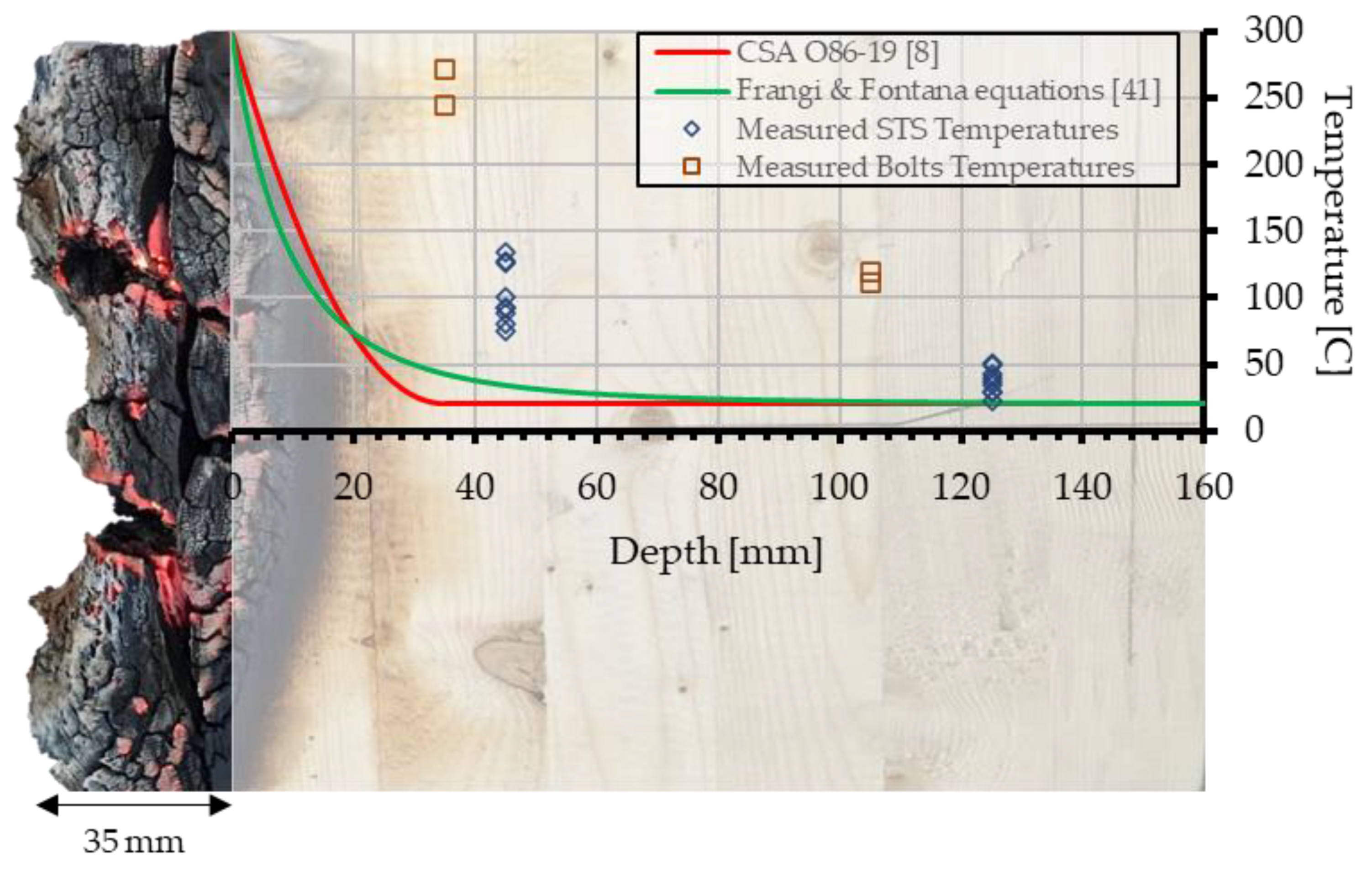
3.1. Effect of Temperature Distribution along the Fasteners

Exposing the tip or the head of the STS did not have much influence on the temperature distribution along the fastener shank. When the tips were exposed, thermocouples at 120 mm of the STS showed the same temperatures of 68 °C as those when the heads were exposed after two hours, as illustrated in Figure 7. The low temperatures are most likely explained by the thermal properties of the glulam’s slow heat penetration along the screw, regardless of the exposed side. Adding a timber cover at the exposed tip had a positive impact on the thermal distribution along the screw shank. For instance, the temperature difference (∆T) at mid-length showed a lower temperature when the exposed side was initially protected by 20 mm of glulam, even after two hours (see Figure 7). This effect was also noted from the thermocouples at the exposed tips until about 90 min when the temperatures of 750 °C were similar as the exposed head. Covering the screw with a timber cover slowed the thermal penetration under the exposed surface and maintained lower temperatures along the screw. Figure 7 also shows that the threaded length of the screws did not have a significant influence on the temperature distribution. For similar temperatures of 750 °C at the head of the fasteners, the temperatures of 218 °C at the mid-length and 72 °C at the tip showed the same measurement for the partial-thread screws and the full-thread screws.
In Figure 8, higher temperatures were reached through the fastener shank with increasing fire duration, regardless of fastener types. With continued heating, the heat flux through the fastener shank depends on the fire duration conducted by a heating rate ranging between 10 and 50 °C/min for the unprotected steel member [37]. Longer exposure causes higher temperatures through the screw and rising the thermal capacity of fastener into timber, as obtained. The shank diameter of the fastener was also influencing the temperature distribution along the screws as well. The larger heated area of the fastener increases the amount of heat rate per unit area through the fastener shank, resulting in an increasing heat flux into steel element. For instance, the Ø10 mm screws showed higher temperatures along the shank than those with Ø8 mm screws. Furthermore, and as expected, the bolt-type fasteners reached much higher temperatures during the tests due to the larger thermal capacity of the bolt diameter. For similar temperatures at the fastener heads, the temperature distribution along the bolt shank was significantly greater than that of the smaller-diameter STS (see Figure 8). The average mid-length bolt temperature of 165 °C was reached after 30 min of radiant heat exposure while the same shank temperature was reached after 90 min for the Ø10 mm STS. After two hours of exposure, the temperatures at the tip of the shank remained lower than 73 °C for the STS, whereas it was greater than 165 °C for the bolts. Using smaller and more slender screws thus limited the temperature distribution under 100 °C after two hours compared to bolts, wherein temperatures reached much higher levels due to the larger thermal capacity of the steel shank.
Hofmann et al. [18] and Owusu [38] have also evaluated the temperature distribution for STS and bolts under one hour and 30 min of standard fire exposure, respectively. Values of 60 °C and 100 °C were obtained at the mid-length of Ø6 mm and Ø12 mm STS under one hour of standard fire exposure in Hofmann et al. [18]. On the other hand, values around of 100 °C, 200 °C and 310 °C were obtained at the mid-length of Ø19 mm top bolts under 10 min, 20 min, and 30 min of standard fire exposure in Owusu [38], respectively. As expected, the thermal capacity of the shank diameter has greatly influenced the temperature distribution of the fastener with higher temperatures for bolt-type diameters than screw-type diameters, while smaller values were recorded for the Ø6 mm screws than the corresponding temperatures of Ø12 mm screws. Compared to the tested fasteners with the measured temperature in our study, this effect is also confirmed by the increases of temperature distribution with increasing diameter of the fastener (i.e., Ø6 mm < Ø8 mm < Ø10 mm < Ø12 mm for STS). However, compared with the bolt-type fasteners, the screw-type fasteners lead to much lower temperatures along the shank. Although the work of Hofmann et al. [18] and Owusu [38] are limited to shorter fire exposure than in this paper, the results from both researches are consistent with the average temperature profiles obtained herein at a similar time exposure. Therefore, the results support the assumption that the heating rate through the fastener shank is proportional to the amount of exposed area and thereby contributes to local charring of the timber surrounding the steel elements.

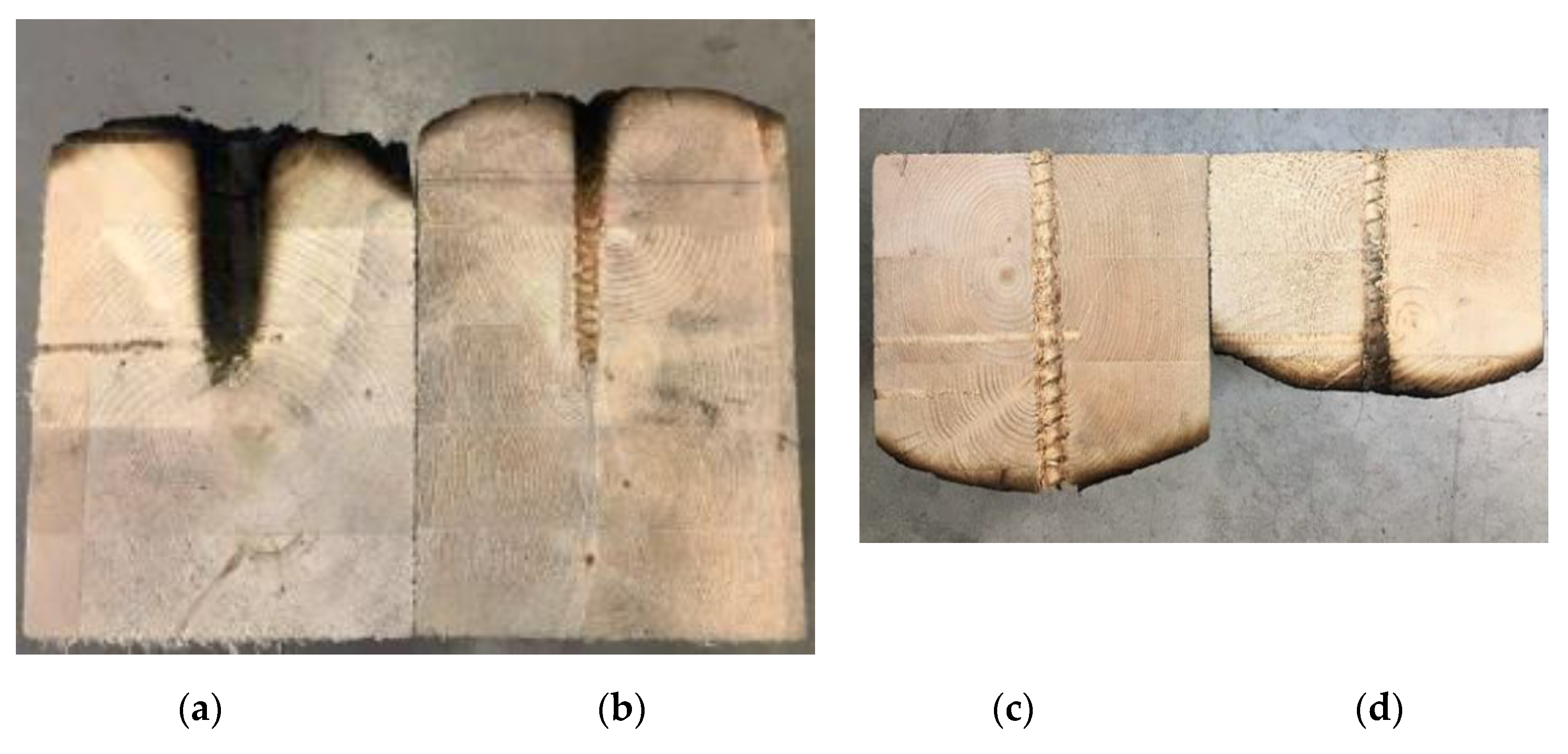
3.2. Effect of Fasteners on the Timber Charring Rate

The average values of the charring depth and rate for all the tests were measured and are presented in Table 3. The length of localized charring along the fastener’s shank is also presented.
As one would expect, the glulam charring rate was not constant throughout the fire exposure. Due to the evolution of the insulation effect given by the charcoal formed at the exposed surface of the specimens, the charring rate decreased into timber, as also reported in the literature [39,40,41]. The thickness of the charred layer increased with longer exposures times limiting the heat penetration, and ultimately, the temperature profile into the timber. Moreover, as the specimen chars, its surface moves away and the incident heat flux imposed at that moving surface is reducing, thereby reducing the resulting charring rate. For instance, the charring rate in the first hour observed for the exposed STS head is consistent with those in various glulam specimens exposed to a constant heat flux without fastener reported by Yang et al. [40]. However, the charring rate after an exposure of two hours is lower than that after an exposure of one hour. Due to its insulative effect, the charred wood prevented the charring depth of the specimens and decreased the heat penetration inside the timber under longer time exposures.
Furthermore, on the insulation effect of the char layer, the charring rate also influenced the relative exposure of wood and steel elements. By exposing an initial 20 mm of glulam cover between the exposed surface and the tip of the fastener, a char layer is formed, and its low thermal conductivity protects the underlying timber and steel against heat [14]. For instance, the charring rate of the STS with exposed head was higher than the charring rate of the STS with exposed tip (see Table 3). With continued heating, the thermal degradation of the initial glulam cover prevents the exposure of the steel element while the unprotected fastener heads increase warming inside. The fastener contributes by increasing the charring depth due to the larger thermal capacity. A deeper char layer was formed around the fasteners shank while the three unexposed sides remained unchanged on the surface (see Figure 9). Due to the high conductivity of the steel, the heat transmitted through the fastener shank leads to higher temperatures along the cross-section area and locally increases wood temperatures. Moreover, this gradient of heat transfer through the fastener shank is controlled by the slenderness of the fastener (i.e., the ratio of their diameter to their length). The combination of the heated surface and the ability of the fastener to penetrate the timber further away from the exposed surface gives the capacity of the thermal properties of timber to prevent its propagation along the fastener [14]. This effect was greatly observed when comparing the bolt and the STS after two hours of exposure, as illustrated in Figure 9a,b.
For the specimens with the head exposed (i.e., unprotected), the charring depth was limited along the first few threads of STS shank while the bolt shank created a charring depth along the entire shanks after two hours of exposure. This difference was caused by the larger heated area of bolt shank that conducted heat faster within the specimen and consumed timber surrounding the steel shank, whereas small, long, and slender screws had limited heat transfer into the timber. Although the STS limited thermal penetration, localized charred threads were observed along the first few threads (see Figure 9b,d). The characterization of this locally charred penetration area was measured and is also presented in Table 3. Due to the high thermal conductivity of the steel shank, the heat conducted through the fastener heats up the timber inside and the wood fibers around the fastener, as previously discussed. The same phenomenon was observed for the STS screws initially protected by 20 mm of glulam after two hours of exposure, as shown in Figure 9d. Frangi & Fontana [41] reported that the thermal penetration depth, defined as the distance from the char layer to the wood that is still at ambient temperature, increased with a longer fire duration. Under long fire durations, the cracks formed in the char layer can accelerate the temperature rise through the charred layer and warm up the timber inside. Assuming the charcoal starts glowing at 500 °C [42], the cracking in the charred layer allows the heat to pass through the char layer and affects the temperatures into timber. Therefore, the temperature profiles through wood members exposed to fire depend majorly on the relative exposure of the wood and steel elements, as well as the fire duration which affects the temperature distribution along the fastener shank.

3.3. Effect of the Withdrawal Resistance on Self-Tapping Screws

During the mechanical tests, all pull-out tests of STS failed due to withdrawal of the screw from the glulam and characterized as a shear failure of the wood fibers along the fastener shank. This was expected because the axial tensile strength of the STS was higher than the anticipated withdrawal capacity of the glulam. Given that the load capacity of the fastener majorly depends on the mean relative density of the timber and the yield point of the steel [24], the key factor in the failure is the capacity of wood fibers to resist shear forces, which are transferred through the threaded length of the screws [12]. The average withdrawal resistance for the STS under ambient and fire conditions are presented in Table 4.
As expected, and reported by Abukari [24], the withdrawal strength increased with screw diameter with a higher tensile strength of the fastener. For instance, the average withdrawal strengths of 0.176 kN/mm and 0.192 kN/mm were calculated in ambient conditions for Ø8 mm and Ø10 mm full-thread screws, respectively, and using a length of penetration of 120 mm. This relationship was not linear due of the variability in the wood properties (i.e., density, moisture content, and the grain orientation). With the variability on the wood fibers’ strength, the withdrawal strength can be affected and can modify the global behavior of the material with higher variability [24]. However, the average withdrawal strengths obtained in this study were consistent with those reported in glulam or softwood elements by Abukari [24], Gehloff [43], and technical values given by MTC Solutions tests [44]. The latter publishes an average value of 0.183 kN/mm and 0.206 kN/mm for Ø8 mm and Ø10 mm STS, respectively.
In fire conditions, the average withdrawal load resistance decreased with increasing fire duration. For instance, the decrement was 22% and 34% between ambient conditions and one hour of fire exposure for Ø8 mm and Ø10 mm diameters with exposed heads, respectively. The decrement was 51% and 62% between ambient conditions and two hours of fire exposure for Ø8 mm and Ø10 mm diameters with exposed heads, respectively. The high heat-conduction of steel-conducted temperature along the fastener shank induced a local loss of wood fiber strength and specific gravity due to elevated temperatures [14,15]. Increasing the wood temperature at the vicinity of the fastener shank locally weakens the wood fibers surrounding the threaded shank and decreases the ability of timber to resist withdrawal forces. With the heating rate dependent on time exposure, higher and deeper temperature profiles are obtained through the fastener shank; therefore, the overall withdrawal resistance decreases as less threads are fully secured in unaltered wood fibres that are still at ambient conditions. In other words, the initial depth of STS penetration is reduced by decreasing the withdrawal strength of the timber under exposure. Figure 10 and Figure 11 show the load-displacement curves for the STS pull-out tests at elevated temperatures.
As opposed to the results obtained from the pull-out tests in ambient conditions, withdrawal tests in fire conditions exhibited a greater plastic behaviour in the screws with longer exposures. Long exposure times decreased the mechanical properties of the steel for a more asymptotic response up to the maximum withdrawal resistance. This behavior causes further strain after the yield point is reached, which is characterized as a plastic deformation [45,46]. In this study, a more nonlinear behavior response up to the failure point was observed when exposed to longer times because the elevated temperature became deeper along the STS shank. However, the temperature-dependant reduction of the mechanical properties of the steel is not significant in comparison to the reduction of the withdrawal strength of the timber, as explained by Erchinger et al. [47]. Therefore, the results suggest that the failure of STS connections is influenced by the strength reduction of the timber as it heats up (i.e., residual cross-section of the timber element and localized charring) due to the heating area of the steel element.

3.4. Effect of the Withdrawal Resistance on Self-Tapping Screws

The glulam sections were reduced accordingly to replicate one and two hours of standard fire exposure, and the resulting lengths of penetration of the STS at those times, as mentioned previously in Section 2.3.2. Failure mode due to withdrawal of the screw was observed for all vertical load tests at ambient conditions, similarly to the pull-out tests. The average withdrawal resistance for the screw connections tested in the vertical load tests are presented in Table 5.
Figure 12 showed the load-displacement curves per connection for 4 × Ø8 mm screws at an angle of 45 degrees by reducing the section of glulam after one and two hours of standard fire exposure. Reducing the fastener’s length of penetration into the timber, the withdrawal resistance of STS decreases, thus reducing the connection capacity. For instance, the decrement was 23% between ambient conditions and one hour of exposure, and 63% between ambient conditions and two hours of exposures for Ø8 mm STS connections, respectively. This reduction for inclined full-thread screws is consistent with the decrement of the pull-out tests. Furthermore, the same failure mode was obtained as at ambient conditions with the reduced section of glulam after one and two hours of standard fire exposure, which confirm that the residual section of the element maintained properly its structural capacity.
As noted previously, there are currently no design provisions for STS in CSA O86-19 [8,24]. It has been suggested that the withdrawal resistance equation provided in the CCMC evaluation report [20] can be used as a viable model for STS with consideration of the group effect for screwed connections in CSA O86-19 [8,29]. The factored withdrawal resistance, Prw,α, loaded at an angle (α) relative to the grain direction, can be calculated using Equation (4).
P rw , α = ϕ 0.8   ·   δ ( b   ·   0.84   ·   ρ ) 2 ·   d   ·   l ef   ·   10 6 sin 2 α + 4 3 ·   cos 2 α ·   K D   ·   K SF
where φ is a resistance factor (0.9), 0.8 is an adjustment factor for standard term loading, δ is a material adjustment factor (82 for ρ ≥ 440 kg/m3), b is 1 for DFir-L, SPF, SYP, WRC, and Hem-Fir, ρ is the mean oven-dry relative density (470 kg/m3), 0.84 is an adjustment factor to convert the mean oven-dry oven density to the fifth percentile value, d is the outside screw diameter (8 mm), lef is the length of threaded shank penetration (subtracting length of the tip) (mm), α is the screw angle relative to grain direction (45 degrees), KD is a load-duration factor, and KSF is a service condition factor.
Then, the ultimate capacity of inclined screws, N′, will be limited by withdrawal resistance in the side member, in the main member or screw tensile fracture in the shear plane [27]. Based on MTC Solutions Design Guides [29], the withdrawal resistance cannot exceed the tensile capacity of the screw, which is the un-factored tensile capacity of 15.12 kN for Ø8 mm ASSY, as provided by the manufacturer [20]. One can observe that reducing the timber cross-section decreases the length of the threaded shank penetration into the main timber member and by weakening its withdrawal strength. The capacity of screw connections, Nr, loaded in shear by taking the critical component, is
N r = N · n F · n R · J · K
where N′ is the factored axial resistance of a shear-tension screw in main member (Prw,α cos(β)), β is the angle between screw axis and line of the force, n F is the number of effective fasteners in a row (max {n0.9; 0.9 · n}), n is the number of screws acting together in a row(2), n R is the number of screws acting together in a row(2), J′ = JEJX, the composite modification factor for fastener installation (1) and K′ = KD KSF KT, the composite modification factor for connections.
In an attempt to fairly compare the equations to the test data, some adjustments are required. The load-duration factor, KD, was set to 1.15 in Equations (4) and (5) in accordance for short-term tests [8]. For a spruce-pine glulam, the oven dry density and relative density were 470 kg/m3 and 0.47, respectively. Since the wood moisture content was 12%, the service condition factor (KSF) was set equal 1.0. The STS diameter and penetration length values were the applicable values from the tests. The withdrawal resistance equations are calculated as 31.3 kN, 17.8 kN, and 4.6 kN at ambient conditions, one and two hours of fire exposure, respectively. The decrement is 43% between ambient conditions and one hour of exposure, and 85% between ambient conditions and two hours of exposure for the Ø8 mm STS connections, respectively. The comparison between the design methods and the experimental data did not showed the same decrement. Equations (4) and (5) significantly over-predict the withdrawal resistance of STS connections with greater decrement for longer exposures. Therefore, a more appropriate design equation is needed for the withdrawal resistance of STS connections, which include a better characterization of the penetration length of the fastener into timber and the steel behavior at elevated temperatures.

4. Design Proposal

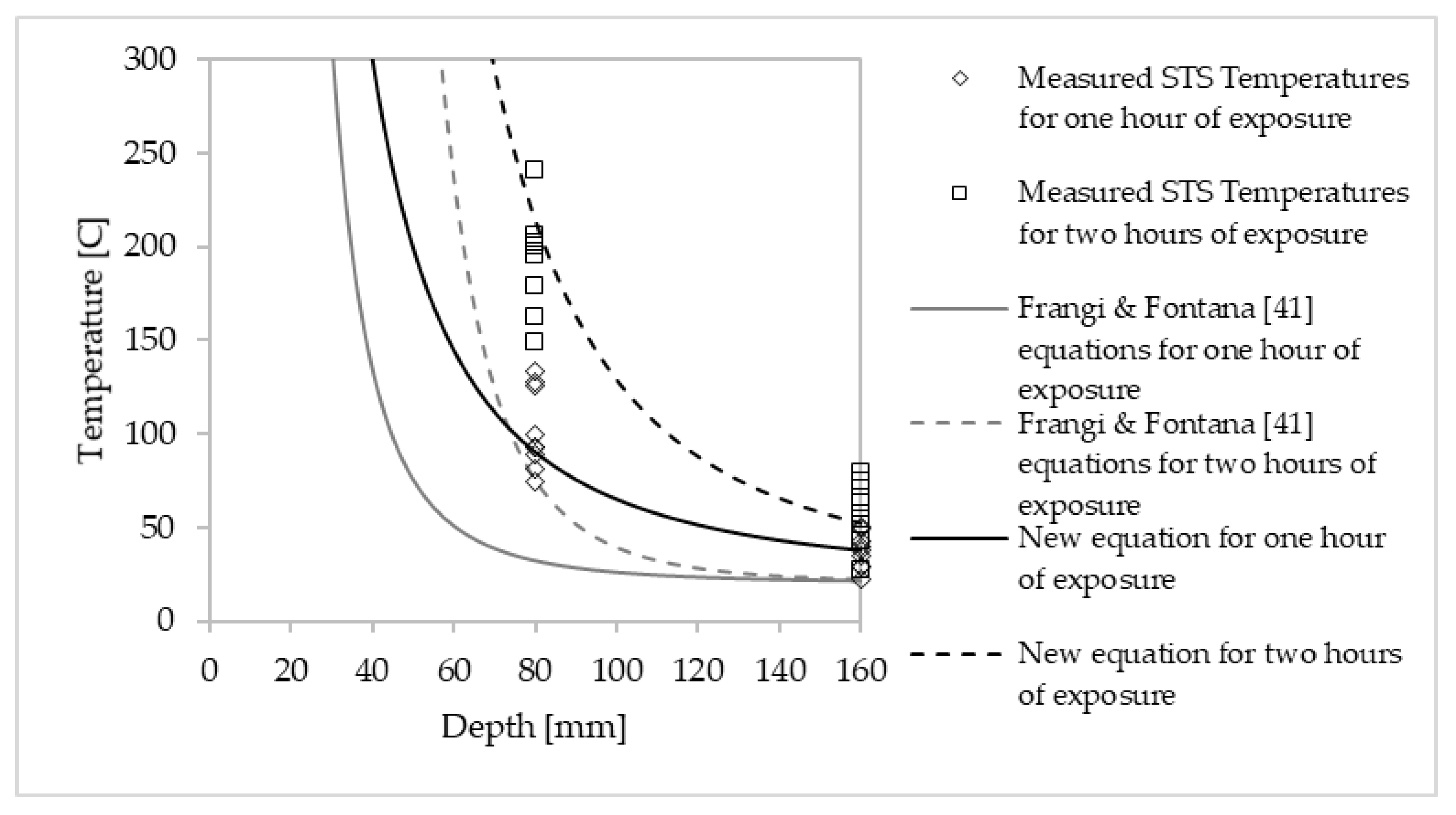
4.1. Charactization of the Heat-Affected Layer

Based on the results presented herein, the combination of the insulation effect of the timber and the favorable geometries of fastener shanks provided a lower heat transfer response for screw-type fasteners than bolt-type fasteners at elevated temperatures. The smaller heated behavior has limited thermal conduction along the cross-section area and maintained the temperature profiles relatively low along the STS shanks for long fire exposures. Although STS represent an encouraging alternative for connections in timber construction, the determination of their load capacity under fire conditions must consider the heat-affected layer, which is the temperature profile behind the char layer [12] that impacts the fastener’s effective length of penetration. The design principles should rely on the residual length of penetration that will provide adequate strength such that the fasteners are within timber that properly retains its structural capacity. Several researches have provided guidelines to characterize the heat-affected layer [40,41]. However, most of these studies were for the temperature profiles of timber sections tested for less than two hours, with the relationship proposed by Frangi & Fontana [41] being the closest model predicting the temperature development in a glulam exposed to a heat flux from three sides [48]. Frangi & Fontana [41] calculate the temperature profile in a wood member subject to the standard fire curve from one side using Equations (6) and (7).
Θ ( x ) = 20 + 180 ( β t x ) α
α ( t ) = 0.025 t + 1.75
where Θ is the temperature in °C as a function of the depth x, β is the charring rate in mm/min, t is the time in min, and x is the depth measured from the surface of the cross-section in mm.
Equations (6) and (7) were derived assuming a char line at the 200 °C isotherm and an ambient temperature of 20 °C. The design method in CSA O86-19 [8] followed a thermal model developed by Janssen & White [49], with assumptions of a charring rate of 0.70 mm/min for glulam, a char line at 300 °C isotherm, an ambient temperature of 20 °C and thermal penetration depth of 35 mm. Substituting these assumptions into Equation (6) results in the following Equation (8):
Θ ( x ) = 20 + 280 ( 1 x 35 ) 2
where Θ is the temperature in °C as a function of the depth x, and x is the depth measured from the surface of the cross-section in mm.
Considering the average char rating of 0.58 mm/min obtained from the small-scale fire tests of the STS with the head exposed to the constant heat flux for one hour, the temperature profiles using Equations (6)–(8) (with β = 0.58 mm/min and t = 60 min) can be calculated and compared to the measured temperatures at mid-length (45 mm) and at the tip (125 mm) of the tested STS with the head exposed. A depth of 35 mm from the char layer is deducted from the initial positions (e.g., 160–35 = 125 mm), as shown in Figure 13. As expected, the measurement STS temperatures are much higher than the timber temperature profiles predicted by Equations (6)–(8), namely, due to the high conductivity of the fastener shank and the effect of a longer exposure. Both calculated temperature profiles are applicable to the timber alone and did not include a fastener being inserted into it. Indeed, the heating rate through the steel element increases the temperature profiles along their shanks while the glulam inside would remain at ambient temperatures without fastener inserted, as demonstrated by Erchinger et al. [47]. Additionally, Equation (8) implied in CSA O86-19 [8] does not include the effect of the fire duration on the thermal penetration depth, which is the distance from the char line to the part of wood that is still at an ambient temperature. Influenced by the duration of fire exposure, Frangi & Fontana [41] estimated the thermal penetration depth as being from 25 to 50 mm with an increasing fire duration, whereas the 35 mm implied in CSA O86-19 [8] is kept constant regardless of the fire duration. When including in Equations (6) and (7) the impact of the fire duration on the thermal penetration depth, the equations seem to have the proper power function form. However, new variables need to be created to consider the heated area of the fastener shank.
Based on all the temperatures measured for STS with exposed heads, new variables were developed using fitting curves with nonlinear regression and assuming no reduction in steel yield strength up to 400 °C in accordance with EN 1993-1-2 [33] and an ambient temperature of 20 °C [10]. With an average charring rate of 0.58 mm/min and 0.52 mm/min for one and two hours for the exposed STS head (see Table 3), Equations (9) and (10) have therefore been developed for the calculation of the temperature profiles of STS inserted in a glulam member with an initially unprotected exposed head and exposed to a constant heat flux from one side.
Θ ( x ) = 20 + 370 ( β t x ) α
α ( t ) = 0.01 t + 1.4
where Θ is the temperature in °C as a function of the depth x, β is the charring rate in mm/min, t is the time in min, and x is the depth measured from the surface of the cross-section in mm.
Figure 14 shows the measured temperatures after one and two hours for STS with heads exposed to a constant heat flux of 50 kW/m2. The depth x is measured from the surface of the original glulam cross-section. The new calculation model—Equations (9) and (10)—results in closer calculated temperatures along the fastener shank for one and two hours of exposure. For one hour of exposure, few measured temperatures are slightly higher than the predicted temperature due to the variability of temperatures at mid-length through the STS between one and two hours. However, for the two-hour exposure, the equation predicts well the temperature profile along an STS of 160 mm in length, with most of the data being on the conservative side (i.e., below the calculated temperature profile). Based on the temperatures measured at mid-length and at the tip, the proposed calculation model gives reasonable temperature profiles along the fastener’s shank for Ø8 mm STS and Ø10 mm STS.

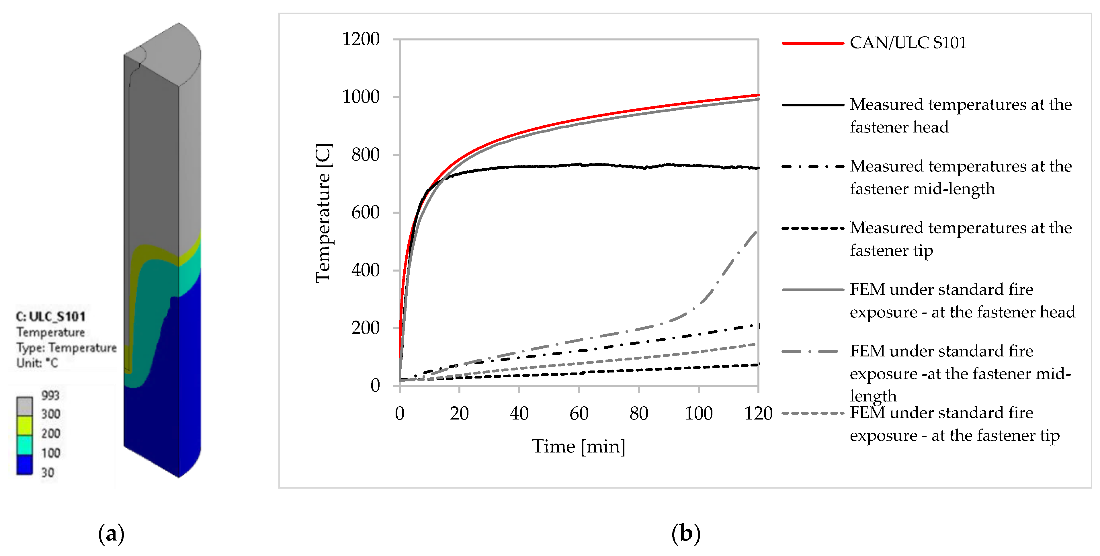
4.2. Verification and Validation from Heat Transfer Modelling

In an attempt to verify and validate the temperature profiles of Equations (9) and (10) when exposed to the standard temperature–time curve CAN/ULC S101 [6], an extensive thermal numerical study was performed using FEM in ANSYS software. The transient heat transfer modelling gives the distribution of the temperature field on the nodes of each element constituting the assembly for each time step. Temperatures were measured at a depth of 0, 80 and 160 mm from the surface exposed to fire, i.e., at the same locations along the fastener shank used to measure the temperature during the small-scall fire tests. Figure 15 shows the comparison between the fire tests and FEM predictions for a Ø10 mm full-thread STS exposed to a constant heat flux of 50 kW/m2 up to two hours. The experimental and numerical results were in good agreement.
Applying a constant heat flux of 50 kW/m2 at the top surface of the STS head and glulam resulted in similar temperatures to that recorded from the small-scale fire tests. While the predicted curves are slightly higher at the tip of the STS, the heat transfer response was generally in agreement with the temperatures measured by the thermocouples at the same locations along the fastener shank. The FEM assumption of analyzing only one quarter of the specimen with a cylindrical shank did not seem to have affected the heat transfer response. These results suggest that the chosen thermal properties in the FEM modeling are satisfactory. In an attempt to compare the charred layer from the heat transfer model to that measured from the tests, the charred layer can be calculated numerically by considering all areas with temperatures greater than 300 °C, used as the temperature isotherm at which mechanical proprieties of the wood are set to zero (represented as the grey color in Figure 15a. By applying 300 °C isotherm of the model as shown in Figure 15a, the charred layers estimated numerically for the Ø10 mm full-thread STS are 41 mm and 64 mm under one and two hours of exposures, respectively. This is consistent with the measured charred layer form the small-scale fire test in Table 3. The thermal model also showed the localized char along the STS shank, as observed in the experimental results. This is due to the presence of steel, which conducts heat faster along the fastener inside the timber. When moving away from the steel shank, the glulam cross-section shows low temperature, near to that of ambient conditions. The good insulation of timber prevents its propagation on all cross-sections by maintaining low temperature while the steel elements led to much higher temperatures inside the timber.
Furthermore, the standard temperature–time curve CAN/ULC S101 [6] was also applied in the FEM model in an attempt to predict the heat transfer under standard fire exposure. Temperatures were also measured at depths of 0, 80 and 160 mm from the initial surface exposed to fire. Figure 16 illustrates the evolution of temperature for a Ø10 mm full-thread STS exposed for one and two hours to the standard fire at the surface of the specimen. While the exposures are not similar, the experimental data from the small-scale fire tests are shown to compare the effect of the greater temperature from the CAN/ULC S101 standard fire. One can observe that the severity of the CAN/ULC S101 ultimately raises the shank temperature faster than when exposed to a constant heat flux of 50 kW/m2.
In an attempt to validate the heat transfer model response under standard fire exposure, the glulam residual cross-section can be compared using the one-dimensional charring rate in CSA O86-19 [8] and by considering all areas with temperatures lower than 300 °C, as proposed previously. By applying the 300 °C isotherm of the model, as shown in Figure 16a, the charring rate estimated numerically of the opposite (unheated) side of the Ø10 mm full-thread STS (i.e., where no influence of heat transfer of fastener into glulam specimen is observed) was 0.66 mm/min and 0.73 mm/min under one and two hours of fire exposure, respectively. This is consistent with the one-dimensional charring rate of 0.65 mm/min from CSA O86-19 [8]. However, and as expected, applying the standard temperature–time curve at the top of the STS head and glulam surface resulted in higher predicted temperatures when compared to that of the small-scale fire tests, namely for the two-hour exposure. Under the standard fire exposure, the heat flux at the top surface becomes rapidly greater than that of the small-scale fire test exposure, which increases the heat transfer through the fastener and results in higher temperatures into the glulam. Influenced by the incident heat flux and high conductivity of steel, longer exposure times increase the temperature distribution along the fastener shank to much higher temperatures inside the timber. This effect was observed when comparing the temperature–time curve from the heat transfer model and those from Equations (9) and (10) to the measured temperatures reported in this study, as shown in Figure 17. While the curves of Equations (9) and (10) predict the thermal response well, the heat transfer model under standard fire exposure was expected to be higher than the measured temperatures.
In our study, the measured temperatures are for a constant heat flux of 50 kW/m2, corresponding to approximately 10 to 15 min of the standard temperature–time curve as previously discussed by Sultan [34]. To develop a better numerical prediction of measured temperature profiles under the standard fire exposure, further studies should be conducted in the future by considering the parameters discussed in this study and for standard fire exposure up to two hours. Otherwise, the heat transfer model under a constant heat flux of 50 kW/m2 predicts well the temperature profiles behind the char layer. The proposed calculation model can also be used to predict the heat-affected layer used for evaluating the residual resistance of STS.

4.3. Determination of the Withdrawal Resistance of Self-Tapping Screws

To develop a new calculation design for a better prediction of the fire-resistance for STS connections, it is essential to determine the heat-affected layer that starts to reduce the mechanical properties of timber. When timber is exposed to fire, all free moisture will start to evaporate as the timber temperature rises above 100 °C [50]. The interaction with moisture content is a key parameter for wood properties and influences the embedment and withdrawal strengths of fasteners in timber at elevated temperatures. Norén [51] developed a bilinear relationship for the temperature-dependent reduction of the strengths of timber at 100 °C. This relationship has since been implemented in EN 1995-1-2 [10] for advanced calculations. For instance, the compressive strength of timber at 100 °C is reduced to 25% of its ambient properties, and then linearly to 0 % at 300 °C, which represents the char layer. While the char layer may protect well at high temperatures at the surface (as previously discussed), the high thermal conductivity of steel used to connect timber elements can heat up quickly and degrade the strength and stiffness of the wood within. The wood fibers surrounding the fastener need to properly retain its mechanicals properties, given the need of the STS to transfer the load along the length of penetration [12]. In an attempt to properly maintain the temperature-dependent reduction of the compressive strength of timber, Barber [12] recommended that the wood temperature at the interface between the fastener and the timber cover be kept to a maximum of 100 °C, so that the underlying timber maintains sufficient residual strength for the connection. Indeed, this temperature isotherm depends on the heat flux through the fastener shank and the fire duration, which ultimately affects the heat-affected layer. With the proposed calculation model with Equations (9) and (10), the temperature distribution along the STS can be predicted under different exposures. The temperature threshold suggested by Barber [12] (T ≤ 100 °C) can be measured at any depth and removed from the fastener’s original length of penetration. The residual length of penetration could also be defined as the initial length of treaded shank penetration into the timber element reduced by the zero-strength threaded length, assumed to have no strength and no stiffness. In an attempt to verify the proposed approach under a long fire exposure, the residual length of penetration can be estimated from the small-scale fire tests and evaluated from the load capacity obtained in this paper. Based on the average charring rate in Table 3 for the STS with exposed heads, Equation (9) is first used to predict the position of the 100 °C isotherm in the timber and is estimated as 75 mm and 112 mm for one and two hours. Beyond that 100 °C threshold, the mechanical proprieties of the timber are not retained properly. Therefore, the residual length of penetration of the STS corresponds to the initial length of 160 mm subtracted by 75 mm and 112 mm for one and two hours. To evaluate the fire performance of STS as a function of fire exposure time, the withdrawal strength per unit length can be back-calculated with the load-capacity obtained in Table 4 divided by the estimated residual length of penetration. Figure 18 shows the average value for each screw diameter under different fire exposures as well as some values of STS found in the literature at ambient conditions [24,43].
When compared to similar average strengths of STS found in the literature at ambient conditions [24,43], the average residual withdrawal strength per unit length does not seem to be influenced by the fire exposure duration, even when the head is initially unprotected (i.e., exposed to fire). The reduction of withdrawal resistance (see Table 4) was induced by the loss of length of penetration into the timber as it heats up due to the high heat-conduction of steel. However, the withdrawal resistance per unit length remains essentially the same as that at ambient conditions, regardless of the duration of fire exposure. The assumption that the temperature-dependent reduction of the timber strength is more significant in comparison to the temperature-dependent reduction of the steel fasteners is validated, which was also validated by the results of Erchinger et al. [47]. When considering the reduction of the cross-section area and the mechanical properties of the wood fibers at a maximum of 100 °C to retain sufficient residual strength, the proposal presented herein is a conservative approach to evaluate the structural capacity of self-tapping screws, regardless of the fire exposure duration.

5. Conclusions

This study presents the fire performance of using self-tapping screws used for connections in mass timber constructions. The experimental program consisted of small-scale tests with perpendicular-to-grain withdrawal tests in an attempt to characterize the fire behavior of self-tapping screws exposed for up to two hours, as required for tall buildings in many countries. The results are also used to validate a three-dimensional transient heat transfer model using the finite element method and to develop design principles facilitating the determination of the fire-resistance of screwed connections.
Influenced by the heating rate through the fastener shank, it was found that the temperature profiles through wood members mainly depend on the relative exposure of the wood and steel elements, as well as the fire duration, which affected the temperature distribution along the fastener shank. The combination of the insulating effect of timber and the favorable geometries when using long and slender fasteners provides longer fire-resistance for screw-type fasteners than bolt-type fasteners at elevated temperatures. Due to the insulative effect of timber, the smaller heated area of the exposed STS surface limited the thermal conduction along the cross-section area and the charred wood prevented the charring depth of the specimens. Mainly influenced by the temperature-dependent reduction of the embedment and withdrawal strengths of the timber, this study presented new design principles to predict the temperature profiles along unprotected STS with the influence of a steel-heated area to determine the residual length of penetration that will provide adequate residual load-capacity under fire conditions. When maintaining an adequate structural capacity of the surrounding wood fibers at a maximum of 100 °C, the capacity of the STS was not influenced with an increase of exposure duration. The design method presented herein allows calculating the residual capacity of unprotected STS exposed to fire for up to two hours. In our study, the measured temperatures are for a constant heat flux of 50 kW/m2, corresponding to approximately 10 to 15 min of the standard temperature–time curve. To improve the numerical prediction of measured temperature profiles under the standard fire exposure, further studies should be conducted in the future by considering the parameters discussed in this study and by using a standard fire exposure of up to two hours.

Author Contributions

M.L.-G.: conceptualization, methodology, software, formal analysis, investigation, and writing—original draft. C.D.: methodology, supervision, validation, and writing—review and editing. P.B.: resources, funding, supervision, and writing—review and editing. All authors have read and agreed to the published version of the manuscript.

Funding

Funding of this project was provided through the Natural Sciences and Engineering Research Council of Canada, through its IRC and CRD programs (IRCPJ 461745–18 and RDCPJ 524504–18) as well as through the Canada Graduate Scholarships Master’s (CGS M) program. Funding was also provided by the industrial partners of the NSERC industrial chair on eco-responsible wood construction (CIRCERB).

Institutional Review Board Statement

Not applicable.

Informed Consent Statement

Not applicable.

Data Availability Statement

The data presented in this study are available upon request to the corresponding author.

Acknowledgments

The authors are grateful to Art Massif, FPInnovations, and MTC Solutions for the materials used for the experiments and the technical support given.

Conflicts of Interest

The authors declare that they have no known competing financial interests or personal relationships that could have appeared to influence the work reported in this paper.

References

  1. Haaland, C.; van den Bosch, C.K. Challenges and strategies for urban green-space planning in cities undergoing densification: A review. Urban For. Urban Green. 2015, 14, 760–771. [Google Scholar] [CrossRef]
  2. Khorasani, Y. Feasibility Study of Hybrid Wood Steel Structures. Ph.D. Thesis, University of British Columbia, Vancouver, BC, Canada, 2011. [Google Scholar]
  3. National Research Council Canada. National Building Code of Canada; National Research Council Canada: Ottawa, ON, Canada, 2015. [Google Scholar]
  4. Buchanan, A.H.; Abu, A.K. Structural Design for Fire Safety, 2nd ed.; John Wiley & Sons Chichester: West Sussex, UK, 2017; p. 415. [Google Scholar]
  5. ASTM International. E119-20 Standard Test Methods for Fire Tests of Building Construction and Materials; ASTM International: West Conshohocken, PA, USA, 2020. [Google Scholar]
  6. Underwriters Laboratories of Canada. Standard Method of Fire Endurance Tests of Building Construction Materials (ULC-S101-07); Underwriters Laboratories of Canada: Toronto, ON, Canada, 2007. [Google Scholar]
  7. International Standard Organization. ISO 834-1: Fire-Resistance Test—Elements of Building Construction—Part 1: General Requirements; International Standard Organization: Geneva, Switzerland, 1999. [Google Scholar]
  8. Canadian Standards Association. CSA O86-19: Engineering Design in Wood; Canadian Standards Association: Mississauga, ON, Canada, 2019. [Google Scholar]
  9. International Code Council. 2018 International Building Code; International Code Council: Country Club Hills, IL, USA, 2017. [Google Scholar]
  10. European Committee for Standardization. CEN, Eurocode 5: Design of Timber Structures—Part 1–2: General—Structural Fire Design; European Committee for Standardization: Brussels, Belgium, 2004. [Google Scholar]
  11. Australian Building Codes Board. The National Construction Code; Australian Building Codes Board: Victoria, Australia, 2019.
  12. Barber, D. Determination of fire resistance ratings for glulam connectors within US high rise timber buildings. Fire Saf. J. 2017, 91, 579–585. [Google Scholar] [CrossRef]
  13. Audebert, M.; Dhima, D.; Bouchaïr, A.; Frangi, A. Review of experimental data for timber connections with dowel-type fasteners under standard fire exposure. Fire Saf. J. 2019, 107, 217–234. [Google Scholar] [CrossRef]
  14. Maraveas, C.; Miamis, K.; Matthaiou, C.E. Performance of Timber Connections Exposed to Fire: A Review. Fire Technol. 2013, 51, 1401–1432. [Google Scholar] [CrossRef]
  15. Peng, L.; Hadjisophocleous, G.; Mehaffey, J.; Mohammad, M. Fire Performance of Timber Connections, Part 1: Fire Resistance Tests on Bolted Wood-Steel-Wood and Steel-Wood-Steel Connections. J. Struct. Fire Eng. 2012, 3, 107–132. [Google Scholar] [CrossRef]
  16. Green, M. TALL WOOD-The Case for Tall Wood Buildings, 2nd ed.; Canadian Wood Council: Ottawa, ON, Canada, 2020. [Google Scholar]
  17. Salenikovich, A.; Moses, D.; Hong, M. Modern Wood Fasteners, Structural Connections. Struct. Mag. 2020. Available online: https://www.structuremag.org/?p=16285 (accessed on 12 April 2021).
  18. Hofmann, V.; Gräfe, M.; Werther, N.; Winter, S. Fire resistance of primary beam-secondary beam connections in timber structures. J. Struct. Fire Eng. 2016, 7, 126–141. [Google Scholar] [CrossRef] [Green Version]
  19. Petrycki, A.R.; Salem, O. (Sam) Structural fire performance of wood-steel-wood bolted connections with and without perpendicular-to-wood grain reinforcement. J. Struct. Fire Eng. 2019. ahead of print. [Google Scholar] [CrossRef]
  20. Canadian Construction Materials Centre. Evaluation Report CCMC 13677-R SWG Assy VG Plus and SWG ASSY 3.0 Self Tapping Wood Screws; Canadian Construction Materials Centre: Ottawa, ON, Canada, 2013. [Google Scholar]
  21. ICC Evaluation Service. ESR-3179: SWG ASSY 3.0 Wood Screws; ICC Evaluation Service: Country Club Hills, IL, USA, 2015. [Google Scholar]
  22. ETA. ETA 11/0190: Self-Tapping Screws for Use in Timber Constructions; Deutsches Institut für Bautechnik: Berlin, Germany, 2018. [Google Scholar]
  23. European Committee for Standardization. CEN, Eurocode 5: Design of Steel Structures, Part 1-1: General Rules and Rules for Buildings; European Committee for Standardization: Brussels, Belgium, 2004. [Google Scholar]
  24. Abukari, M.H. The Performance of Structural Screws in Canadian Glulam. Master’s Thesis, McGill University, Montreal, QC, Canada, 2012. [Google Scholar]
  25. Guo, J.; Shu, Z. Theoretical Evaluation of Moment Resistance for Bolted Timber Connections. MATEC Web Conf. 2019, 303, 03003. [Google Scholar] [CrossRef] [Green Version]
  26. Canadian Standards Association. CSA 0122-16 Structural Glued-Laminated Timber; Canadian Standards Association: Mississauga, ON, Canada, 2016. [Google Scholar]
  27. Canadian Standards Association. CSA O177-06 Qualification Code for Manufacturers of Structural Glued-Laminated Timber; Canadian Standards Association: Mississauga, ON, Canada, 2015. [Google Scholar]
  28. ASTM International. D1761-20 Standard Test Methods for Mechanical Fasteners in Wood and Wood-Based Materials; ASTM International: West Conshohocken, PA, USA, 2020. [Google Scholar]
  29. MTC Solutions. Structural Screw Design Guide. Available online: https://mtcsolutions.com/resource/structural-screw-design-guide/ (accessed on 25 February 2021).
  30. ASTM International. D7147-11(2018) Standard Specification for Testing and Establishing Allowable Loads of Joist Hangers; ASTM International: West Conshohocken, PA, USA, 2018. [Google Scholar]
  31. European Committee for Standardization. CEN, Eurocode 1: Actions on Structures—Part 1-2: General Actions—Actions on Structures Exposed to Fire; European Committee for Standardization: Brussels, Belgium, 2002. [Google Scholar]
  32. König, J.; Walleij, L. One-Dimensional Charring of Timber Exposed to Standard and Parametric Fires in Initially Unprotected and Postprotection Situations (Rapport I 9908029); Swedish Institute for Wood Technology Research: Stockholm, Sweden, 1999. [Google Scholar]
  33. European Committee for Standardization. CEN, Eurocode 3: Design of Steel Structures—Part 1-2: General—Structural Fire Design; European Committee for Standardization: Brussels, Belgium, 2005. [Google Scholar]
  34. Sultan, M.A. Incident heat flux measurements in floor and wall furnaces of different sizes. Fire Mater. 2006, 30, 383–396. [Google Scholar] [CrossRef] [Green Version]
  35. Dagenais, C. Assessing the Fire Integrity Performance of Cross-Laminated Timber Floor Panel-to-Panel Joints. Ph.D. Thesis, Carleton University, Ottawa, ON, USA, 2016. [Google Scholar]
  36. Werther, N.; O’Neil, J.W.; Spellman, P.M.; Abu, A.K.; Moss, P.J.; Buchanan, A.H.; Winter, S. Parametric Study of Modelling Structural Timber in Fire with Different Software Packages. In Proceedings of the 7th International Conference on Structures in Fire, Zurich, Switzerland, 6–8 June 2012. [Google Scholar]
  37. Outinen, J.; Mäkeläinen, P. Mechanical properties of structural steel at elevated temperatures and after cooling down. Fire Mater. 2004, 28, 237–251. [Google Scholar] [CrossRef]
  38. Owusu, A. Fire Performance of Concealed Timber Connections with Varying Bolt Patterns. Master’s Thesis, Carleton University, Ottawa, ON, Canada, 2019. [Google Scholar]
  39. White, R.H.; Tran, H.C. Charring rate of wood exposed to a constant heat flux. Wood and fire safety. In Proceedings of the 3rd International Scientific Conference, The High Tatras, Slovak Republic, 6–9 May 1996; pp. 175–183. [Google Scholar]
  40. Yang, T.H.; Wang, S.Y.; Tsai, M.J.; Lin, C.Y. The charring depth and charring rate of glued laminated timber after a standard fire exposure test. Build. Environ. 2009, 44, 231–236. [Google Scholar] [CrossRef]
  41. Frangi, A.; Fontana, M. Charring rates and temperature profiles of wood sections. Fire Mater. 2003, 27, 91–102. [Google Scholar] [CrossRef]
  42. König, J. Structural fire design according to Eurocode 5: Design rules and their background. Fire Mater. 2005, 29, 147–163. [Google Scholar] [CrossRef]
  43. Gehloff, M. Pull-Out Resistance of Self-Tapping Wood Screws. Master’s Thesis, University of British Columbia, Vancouver, BC, USA, 2011. [Google Scholar]
  44. Robitaille, D.; (MTC Solutions, Montreal, QC, Canada). Personal communication, 2021.
  45. Pauli, J. The Behaviour of Steel Columns in Fire: Material-Cross-sectional Capacity-Column Buckling. IBK Ber. 2012, 343. [Google Scholar] [CrossRef]
  46. Kodur, V.; Dwaikat, M.; Fike, R. High-Temperature Properties of Steel for Fire Resistance Modeling of Structures. J. Mater. Civ. Eng. 2010, 22, 423–434. [Google Scholar] [CrossRef]
  47. Erchinger, C.; Frangi, A.; Fontana, M. Fire design of steel-to-timber dowelled connections. Eng. Struct. 2010, 32, 580–589. [Google Scholar] [CrossRef]
  48. Yang, T.H.; Wang, S.Y.; Tsai, M.J.; Lin, C.Y. Temperature distribution within glued laminated timber during a standard fire exposure test. Mater. Des. 2009, 30, 518–525. [Google Scholar] [CrossRef]
  49. Janssens, M.L.; White, R.H. Short communication: Temperature profiles in wood members exposed to fire. Fire Mater. 1994, 18, 263–265. [Google Scholar] [CrossRef]
  50. Aseeva, R.; Serkov, B.; Sivenkov, A. Fire Behavior and Fire Protection in Timber Buildings; Springer: New York, NY, USA, 2013. [Google Scholar]
  51. Norén, J. Load-bearing Capacity of Nailed Joints Exposed to Fire. Fire Mater. 1996, 20, 133–143. [Google Scholar] [CrossRef]
Figure 1. Thermocouples position for small-scale fire testing: (a) STS head exposed to fire without low-density refractory insulation; (b) STS head exposed to fire wrapped with low-density refractory insulation.
Applsci 11 03579 g001
Figure 2. Fire test using conical radiant heater at 50 kW/m2: (a) Experimental setup with the fastener head exposed (side view); (b) Experimental setup with the fastener tip exposed (back view).
Applsci 11 03579 g002
Figure 3. Pull-through STS test: (a) Experimental setup for the pull-through test; (b) Location of STS across glulam surface.
Applsci 11 03579 g003
Figure 4. Vertical load test: (a) Experimental setup; (b) STS connections with full-length penetration.
Applsci 11 03579 g004
Figure 5. Thermal proprieties of wood used for the heat transfer model: (a) Temperature–density relationship based on glulam specimen; (b) Temperature–thermal conductivity relationship for wood; (c) Temperature–specific heat relationship for wood. Solid line for thermal properties under a standard fire curve and dashed line for thermal properties under a constant heat flux [10,32].
Applsci 11 03579 g005
Figure 6. Major parameters used for FEM modeling: (a) Temperature–time curve applied at the surface of the specimen; (b) Meshing.
Applsci 11 03579 g006
Figure 7. Time–temperature curves of Ø10 × 160 mm screws with the exposed heads and the exposed tips.
Applsci 11 03579 g007
Figure 8. Distribution of temperatures on unprotected fastener heads under a constant heat flux.
Applsci 11 03579 g008
Figure 9. Charring of fastener under constant heat flux; (a) Unprotected Ø15.9 ×140 mm bolt head exposed for two hours; (b) Unprotected Ø10 × 160 mm screws head exposed for two hours; (c) Protected Ø10 × 160 mm screws (tip exposed) for one hour; (d) Protected Ø10 × 160 mm screws (tip exposed) for two hours.
Applsci 11 03579 g009
Figure 10. Load-displacement curves for Ø8 mm screws: (a) Exposed head; (b) Exposed tip. Solid line for ambient conditions, dashed line for one hour of exposure and dotted line for two hours of exposure.
Applsci 11 03579 g010
Figure 11. Load-displacement curves for Ø10 mm screws: (a) Exposed head; (b) Exposed tip. Solid line for ambient conditions, dashed line for one hour of exposure and dotted line for two hours of exposure.
Applsci 11 03579 g011
Figure 12. Load-displacement plots of Ø8 × 300 mm ASSY VG CSK (FT) connections at 45 degrees.
Applsci 11 03579 g012
Figure 13. Measured temperatures and temperature profiles calculated according to [8,41] after one hour for unprotected fastener heads exposed and 35 mm of char layer.
Applsci 11 03579 g013
Figure 14. Temperature profiles using Equation (9) compared to that of Equation (6) and test data for STS with unprotected heads and exposed to a constant heat flux.
Applsci 11 03579 g014
Figure 15. Numerical modelling of a Ø10 mm full-thread STS exposed to a constant heat flux of 50 kW/m2: (a) Heat transfer model at two hours of exposure; (b) Comparison of numerical and experiment of time–temperature curves up to two hours of exposure.
Applsci 11 03579 g015
Figure 16. Numerical modelling of Ø10 mm full-thread screws under standard fire CAN/ULC S101 [6]: (a) Heat transfer model at two hours of fire exposure; (b) Comparison of numerical and experiment of time–temperature curves up to two hours of fire exposure.
Applsci 11 03579 g016
Figure 17. Measured temperatures of FEM and temperature profiles calculated according to equations for unprotected fastener head exposed under standard fire curve up to two hours of fire exposure.
Applsci 11 03579 g017
Figure 18. Withdrawal strength of Ø8 and Ø10 STS under ambient and fire conditions STS with head exposed to fire [24,43].
Applsci 11 03579 g018
Table 1. Dimensions of self-tapping screws.
Partial-(PT) or Full-Thread (FT)Outside Thread
Diameter (dF)
(mm)
Shank
Diameter (dmin)
(mm)
Length (L)/Threaded Length (LF)
(mm)
Penetration with Exposed Head (H) and with the Exposed Tip (T)
(mm)
PT85160/80160 (H)
120 (T)
106.3160/100160 (H)
120 (T)
FT85160/143160 (H)
120 (T)
106.2160/145160 (H)
120 (T)
FT 18-300/283300/230/171
1 STS used for vertical load test.
Table 2. Dimensions of bolts (using a 38.1 mm (1 ½″) washer).
Fastener Head Diameter (dF)
(mm)
Shank Diameter (dmin)
(mm)
Length (L)/Threaded Length (LF)
(mm)
Lead Hole
Diameter
(mm)
Penetration
(mm)
23.815.9140/3816.8150
Table 3. Average values of charring depth and charring rate for all the tests exposed to a constant heat flux.
Time ExposureFastenersExposed
Side
Charring DepthCharring Rate
Charred Layer (mm)Local Charred (mm)Charred Layer (mm/min)Local Charred (mm/min)
One hourØ8 mm screwsHead34180.570.30
Tip 28-0.46-
Ø10 mm screwsHead36220.600.36
Tip 28-0.47-
Two hoursØ8 mm screwsHead62210.520.18
Tip 61170.510.14
Ø10 mm screwsHead61280.510.23
Tip 57130.420.11
Ø15.9 mm boltsHead741400.621.17
Table 4. Average withdrawal resistance for Ø8 and Ø10 STS under ambient and fire conditions.
Fastener TypeWithdrawal Resistance
Ambient ConditionsHead ExposedTip Exposed
One Hour of ExposureTwo Hours of ExposureOne Hour of ExposureTwo Hours of Exposure
Max Load
(kN)
CoVMax Load
(kN)
CoVMax Load
(kN)
CoVMax Load
(kN)
CoVMax Load
(kN)
CoV
Ø8 × 160 mm FT21.24.6%15.30.3%7.934.7%15.80.7%9.810.9%
Ø10 × 160 mm FT23.01.6%14.95.5%9.033.1%19.72.8%14.30.7%
Ø8 × 160 mm PT12.44.0%10.36.4%7.393.5%10.00.5%3.61-
Ø10 × 160 mm PT20.71.7%13.77.8%7.549.2%15.64.1%8.598.2%
Table 5. Average withdrawal resistance per connection for 4 × Ø8 mm screw at 45 degrees in accordingly presuming a charring rate of 0.7 mm/min under fire conditions.
Fastener TypeLoad-Carrying Capacity
Ambient ConditionsOne Hour of ExposureTwo Hours of Exposure
Max Load (kN)CoVMax Load (kN)CoVMax Load (kN)CoV
Ø8 × 300 mm FT56.32.8%43.65.7%20.80.7%
Publisher’s Note: MDPI stays neutral with regard to jurisdictional claims in published maps and institutional affiliations.

