Abstract
This paper presents a novel self-localization technique for mobile robots based on image feature matching from omnidirectional vision. The proposed method first constructs a virtual space with synthetic omnidirectional imaging to simulate a mobile robot equipped with an omnidirectional vision system in the real world. In the virtual space, a number of vertical and horizontal lines are generated according to the structure of the environment. They are imaged by the virtual omnidirectional camera using the catadioptric projection model. The omnidirectional images derived from the virtual and real environments are then used to match the synthetic lines and real scene edges. Finally, the pose and trajectory of the mobile robot in the real world are estimated by the efficient perspective-n-point (EPnP) algorithm based on the line feature matching. In our experiments, the effectiveness of the proposed self-localization technique was validated by the navigation of a mobile robot in a real world environment.
1. Introduction
One of the most important issues for autonomous robots is to localize their positions in the environment. A mobile robot lacking localization information will have a restricted capability for navigation and exploration. Some general tasks, such as home-care services or industrial applications, become more difficult to accomplish. This led the robotics research community paying more attention to coping with the mobile robot localization problem [1]. The commonly used techniques for environmental perception utilize the sensing data obtained from visual, auditory and tactile sensors. This provides the essential information for mobile robots to detect obstacles, complete missions and build a map of the environment. In addition, there also exist indoor localization techniques based on radio technology. The current 5G network and personal mobile radar can be used for accurate environmental mapping [2,3].
Self-localization is a key technology for autonomous robots, and many researchers have attempted to improve its efficiency [4,5]. In general, various sensors are adopted to acquire the information from the environment and derive the 2D/3D position of the mobile robot for motion planning [6,7]. The position computation can be divided into two different approaches. The first approach is based on the probability estimation methods to calculate the robot’s position. The Kalman filter is frequently used to find the largest probability and update the location state based on the sensor data [8,9,10]. In the previous work, Negenborn illustrated a method using the distributed Kalman filter algorithm with a distributed model predictive control (MPC) scheme for large-scale, multi-rate systems [11]. Ledergerber et al. [12] presented a self-localization technique using the extended Kalman filter and random-walk model with the data collected from ultra-wideband signals.
The other self-localization approach is based on the data registration of the 3D models reconstructed from the real scene environment at different locations. Zhang proposed a technique using the iterative closest point (ICP) algorithm to compute the robot’s movement [13]. The 3D registration is carried out on two sets of sensor data obtained from sonar, a laser rangefinder or an RGB-D camera. Due to its high computational cost and insufficient accuracy, a number of works have been proposed for further improvements [14,15]. In addition, Salvi et al. compared the performance of various registration techniques, including the 3D data obtained from multiple viewpoints [16].
In the past few decades, omnidirectional cameras have been widely adopted to the mobile robot applications due to their capability with observing the panoramic viewpoints of the surroundings [17]. Traditional studies attempted to identify the features of the environment (edges, points or lines) by direct extraction from the images captured by the camera. For mobile robot localization, Tasaki et al. presented a beacon-based technique using an omnidirectional camera [18]. The image features are extracted using SURF with the scale and orientation invariant. Kawanishi et al. proposed a localization method based on the parallel lines appearing in omnidirectional images [19]. The line features in the structured environment are detected using structure-from-motion. There also exist various stereo vision-based approaches using multiple cameras [20]. Nevertheless, the direct use of image information brings disadvantages for robot self-localization, for example, the problems associated with illumination change, motion blur, etc.
In this paper, we present a novel self-localization approach using the generated virtual environment to simulate the robot navigation in the real world. The basic idea is to calculate the localization position through the computer generated virtual environment. In the simulated virtual space, a mobile robot equipped with an omnidirectional vision sensor represents a mirror of its real world counterpart. Since computing the 3D position without the illumination change and noise in the simulated environment is much easier, it is used to process the image features extracted from the real world scenes. In the existing literature, the omnidirectional images are used to directly deal with the objects without the virtual information. This work suggests creating a parallel virtual space which simulates the environment in the real world. A mobile robot navigating along a trajectory is used to evaluate the proposed localization technique.
This paper is organized as follows. In the next section, we introduce the omnidirectional vision system adopted in this work and the catadioptric image projection model. The construction of the virtual space and how to generate vertical and horizontal lines within the structured space are described in the Virtual Environment section. In the section Robot Self-Localization, we formulate the pose of the mobile robot as the efficient perspective-n-point (EPnP) problem and our proposed solution. The implementation and experimental results are presented in the Experiments section, followed by the conclusions in the last section.
2. Omnidirectional Vision System
In this work, we utilized an omnidirectional camera for vision based mobile robot self-localization. Since the relationship between the 3D scene points and 2D image pixels is required, it is necessary to perform the camera calibration. To calibrate a conventional perspective camera, a planar checkerboard is commonly adopted for its simplicity and high accuracy on camera matrix computation [21]. For omnidirectional cameras, Scaramuzza et al. proposed a method to calibrate the non-classic cameras (e.g., catadioptric cameras) based on the polynomial approximation [22]. They estimated the camera parameters by transferring the manually selected 3D feature points on the checkerboard pattern to the image plane.
Figure 1 illustrates the projection models of a perspective camera and an omnidirectional camera. The images captured by the omnidirectional cameras are distorted by reflection from the hyperbolic mirror and refraction from the lens. Thus, the feature extraction on the calibration checkerboard is not so straightforward compared to the perspective projection of conventional cameras. Since large errors will be introduced by the line detection in omnidirectional images, it is necessary to select the point features manually. Consequently, the parameter initialization of the image projection function is a complicated and tedious process. To simplify the parameter initialization problem, Mei and Rives [23] proposed a projection model for catadioptric cameras. Specific imaging reflection functions are formulated for different types of curved mirrors to reduce the projection error via an initialization process. It only requires one to take four points on each image of the calibration board, and all corner features can be extracted automatically based on the estimates from the project model.
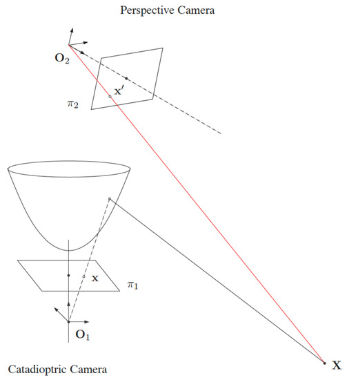
Figure 1.
The catadioptric projection model of an omnidirectional camera. It consists of a hyperbolic mirror for reflection and a pinhole model for perspective projection.
One of the important objectives of our omnidirectional camera calibration is to simplify the feature extraction. The approximated focal length and image center obtained during the initialization process are combined with manually selected four corner points to estimate all other feature points on the calibration images. This greatly reduces the cost for the detection and selection of all features. In addition to the initialization step, we also incorporate the simulation of distortion parameters. It is used to minimize the error through the simulated environment, and provides more accurate calibration results. In this work, the catadioptric projection model proposed by Geyer and Barreto was used to calibrate the omnidirectional camera [24,25].
2.1. Camera Model
The omnidirectional camera realized through the catadioptric imaging system construction can be formulated using a unified sphere model, as shown in Figure 2. Given a point X in the 3D space, it can be projected onto a unified sphere at the point
as illustrated in the figure. The point is then transferred to a new reference frame centered at , and projected onto an image plane at the point
where is the distance between the center of the sphere and the image projection center . The projected point p is given by
This projection model involves a generalized camera matrix K with the focal length , the principal point , the skew factor s and the pixel aspect ratio r. An image pixel in the omnidirectional image is then calculated by the ratios

Figure 2.
The unified sphere model for omnidirectional cameras. It consists of two linear projection steps.
To calibrate the omnidirectional camera, a checkerboard pattern was adopted as the calibration plate. The parameters were initialized according to the type of reflection mirrors. After the focal length and principal point were estimated, the parameters were used to simplify the feature extraction process and further optimize the parameters. The procedure is given as follows.
- Provide the center and border of the reflection mirror as shown in Figure 3a, and then estimate the principal point .
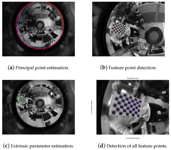 Figure 3. The images captured for omnidirectional camera calibration.
 - Select at least three points on the same line (distorted by catadioptric imaging) from the calibration pattern as shown in Figure 3b, and estimate the focal length .
- Select the four corners on the calibration pattern as illustrated in Figure 3c, and estimate the extrinsic parameters.
- The rest feature points on the calibration can be detected at the sub-pixel resolution via the inverse projection, as illustrated in Figure 3d.
- Finally, the overall optimization should be carried out based on Equation (3) to derive more accurate intrinsic and extrinsic camera parameters.
2.2. Vision Recognition
The surrounding visual information obtained from a mobile robot contains important features for image analysis. The proposed vision system simplified the object detection and recognition procedures using the acquired omnidirectional images with the resolution of . First, the object locations are detected via the color segmentation technique in the omnidirectional image. The position representation is converted to the polar coordinates ,
where is in pixel coordinates, is the center of the omnidirectional image, is the height of the image plane, and is the detected or estimated location of the object in the image coordinates.
3. Virtual Environment
In the existing literature, the vision-based approaches for localization usually analyze the images taken by the cameras, and use the extracted features to derive the robot position. In this work, we first created a virtual space as the counterpart of the real environment. The synthetic image acquired in the virtual space was compared with the real image to deduce the relationship between the virtual and real cameras. It was then used to compute the location of the mobile robot in the real environment.
We first constructed a virtual space for the robot’s movement with several simulated objects, and created an omnidirectional camera in the space at an initial position. As illustrated in Figure 4a, the white sphere indicates the position of the virtual omnidirectional camera, and the space below represents the maximum range for image acquisition. Figure 4b shows an image of several objects and lines in the space captured by the virtual omnidirectional camera. The images of the virtual space and real environment were then compared using the same camera projection model, as described in the previous section for correspondence matching. Once the similar features were identified in both the virtual and real omnidirectional images, the positions of the objects and the camera were estimated in the virtual environment. The relative motion with respect to the starting position was then converted to the real world environment to calculate the mobile robot location.
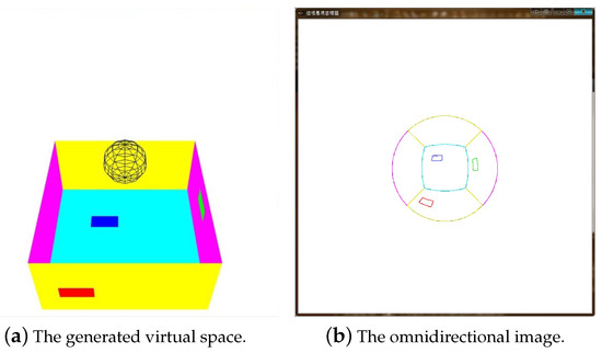
Figure 4.
The simulated virtual environment and the image created by the omnidirectional camera model’s projection.
3.1. Lines in The Virtual Space
In this work, the robot was expected to move in a man-made environment, such as a room or a corridor. Such an environment usually contains horizontal and vertical lines. Thus, we created a virtual space with 3D lines to associate with the real world environment. To match the generated virtual lines with the lines in the omnidirectional image captured in the real world, we used the polar coordinate system to produce the lines in the virtual space. In general, the Cartesian coordinate system was used to create the parallel and orthogonal lines in the space. However, this will make the distribution of the 2D lines very uneven in the captured image. Figure 5 shows the parallel lines generated in the virtual space and captured by a virtual omnidirectional camera. To deal with this problem, we use the polar coordinate system to generate the 3D lines in the virtual space. These lines are expected to locate in the virtual environment with the dense appearance as illustrated in Figure 6a. The appearance in the omnidirectional image is shown in Figure 6b. With this process the polar coordinate system is able to avoid the computational cost.
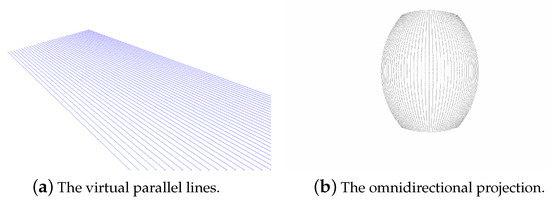
Figure 5.
The parallel lines generated using the Cartesian coordinate system and captured by an omnidirectional camera.
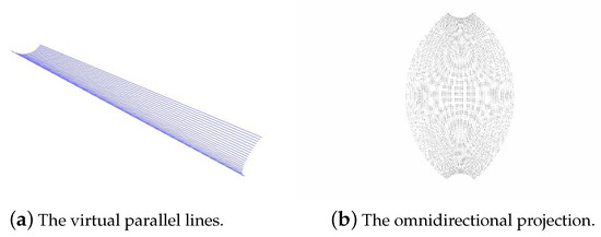
Figure 6.
The parallel lines generated using the polar coordinate system and captured by an omnidirectional camera.
3.2. Matching of Virtual Images to Real Images
The synthetic image generated in the virtual space is compared with the real image captured by the omnidirectional camera. The line features in the synthetic image is matched with the edges in the real image. Once the correspondences are identified, the matched 3D lines are preserved in the simulated environment. These virtual lines are then used to compute the position of the virtual camera in the 3D space. Consequently, the relationship between the virtual lines and the virtual camera is proportional to the relationship between the edges and the omnidirectional camera in the real world environment. The location of the mobile robot is then calculated via the transformation.
In the implementation, the robot’s motion was also taken into account to calculate the camera pose. We adjusted the angles of virtual lines to approximately match the edges in the omnidirectional images. The matching steps are as follows:
- A series of horizontal and vertical lines are generated in the virtual space, as illustrated in Figure 6a.
- The lines in the virtual environment are projected onto the synthetic omnidirectional images, as shown in Figure 6b. In Figure 7d, the lines in different colors correspond to the horizontal and vertical lines, respectively.
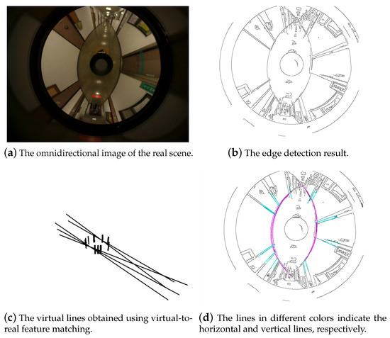 Figure 7. The line matching between the virtual room and the real room.
 - An input image (see Figure 7a) captured by the omnidirectional camera is used for mobile robot localization.
- The edge detection is carried out on the omnidirectional image and the result is shown in Figure 7b.
- Compare the synthetic lines in the virtual space captured by the virtual camera and the edges in the real omnidirectional images.
- Rotate the virtual image for line matching and re-project them to the real image. The action of re-projection is to gain more closed match lines. Figure 7d shows the re-projection result.
- Matching lines are created in the virtual environment as illustrated in Figure 7c.
4. Robot Self-Localization
The image projection of the simulated lines are matched to the lines in the real world, and applied to derive the robot motion in the virtual environment. It is assumed that the surrounding environment is fixed, and the robot captures the images in a moving trajectory. In this work, we use the perspective-n-point (PnP) algorithm to compute the robot motion. The algorithm estimates the camera position in 3D with respect to a series of 3D known feature such as points and lines. It is efficient to use linear equations to solve the PnP problem, but this has to result in a larger position estimation error [26]. A better solving strategy is to adopt nonlinear iterative equations to achieve high accuracy [27]. Our method is based on the efficient perspective-n-point (EPnP) algorithm proposed by Lepetit et al. [28] to estimate the virtual camera position during the robot motion.
In the EPnP algorithm, we first select four non-coplanar points as reference points. Their coordinates in the camera reference system are derived according to the 2D image points and the relationships between 3D points and the reference points. Let be n points in the 3D space, and and for be the four reference points in the world and camera coordinate systems, respectively. Then the transformation between and is given by
where are the coordinates of taking the reference points as basis. Similarly, we have
Thus,
where represents the projection of and A is the intrinsic camera parameter matrix.
Let and for given N points. The right-hand side of Equation (8) can be written as M with
where
Thus, the above equation can be solved by singular value decomposition. Given the world coordinates and the camera coordinates , the relationship between and is written as
by Equations (6) and (7). The extrinsic camera parameter matrices R and T can then be derived with the closed-form solution [29].
To apply the EPnP algorithm to estimate the camera’s position in the virtual environment, we define a set of 3D points and the corresponding 2D points detected in the acquired omnidirectional images. The second set of 3D and 2D point correspondences is then obtained in the omnidirectional image captured after the robot’s motion. As illustrated in Figure 8, the EPnP algorithm is used to compute the transformation between the two sets of 3D and 2D point correspondence. This provides the rotation matrix and translation vector of the robot movement.
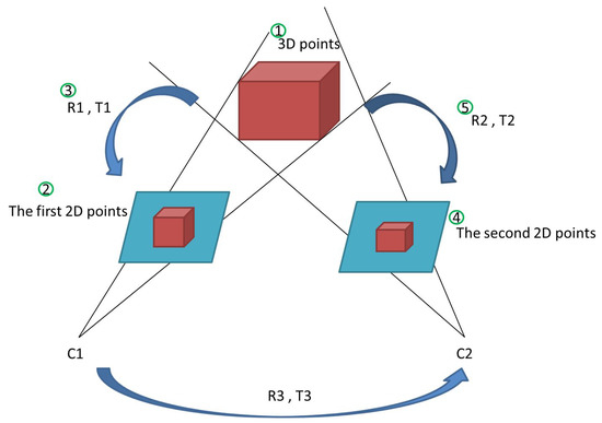
Figure 8.
The computation of relative camera position and robot motion using the efficient perspective-n-point (EPnP) algorithm.
5. Experiments
A mobile robot equipped with an omnidirectional camera as shown in Figure 9 was used in our experiments. The omnidirectional vision system placed on top of the robot contained a curved mirror and a Sony X710 video camera. The software was developed with Visual Studio with OpenCV and OpenGL libraries under Windows Operation System. The virtual environment was modeled based on its real-world counterpart, with the dimensions multiplied by a scale factor. It was constructed using OpenGL with the geometric primitives, including the corridor, walls, roof, doors, and windows. The omnidirectional imaging model was used to create the virtual camera for image synthesis.
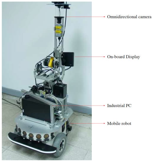
Figure 9.
A mobile robot equipped with an omnidirectional camera is used in this work.
In the first experiment, an image sequence was captured and processed frame-by-frame when the mobile robot moved in a straight line. Figure 10 showed the acquired images for the self-localization computation. For the input image, as shown in Figure 11a, the edge detection was first carried out to obtain an edge image (see Figure 11b). The parallel horizontal and vertical lines constructed in the vertical space are illustrated in Figure 11c. Figure 11d shows the overlay of the edge image with the virtual lines projected on the omnidirectional image according to the catadioptric projection model. By matching the line features from the synthetic and real images, the true horizontal and vertical lines in the real environment could be identified, as illustrated in Figure 11e. The corresponding lines in the virtual space (see Figure 11f) were then used to calculate the mobile robot’s position.
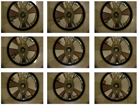
Figure 10.
The omnidirectional images used for the self-localization in the first experiment. The mobile robot moved in a straight line when capturing the images.
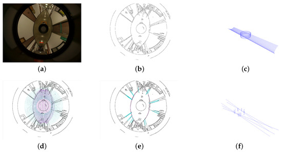
Figure 11.
The mobile robot self-localization using omnidirectional images. (a) An input real image; (b) the edge detection result; (c) the parallel horizontal and vertical lines constructed in the vertical space; (d) the overlay of the edge image with the virtual lines projected on the omnidirectional image; (e) the identified horizontal and vertical lines in the real world scene; (f) the corresponding lines in the virtual space for localization computation.
In the second experiment, the mobile robot moved on non-smooth ground to evaluate the self-localization capability. Figure 12 shows the image sequence to derive the robot motion trajectory. The self-localization results for the first and second experiments are shown in Figure 13a,b, respectively. In the figures, the blue dot represents the localization of the mobile robot in the environment. It consists of the forward direction, horizontal and vertical displacements. The mobile robot moved smoothly in the forward direction, as illustrated in Figure 13a. Several data points of the trajectory in Figure 13b were due to the altitude changes in the robot’s motion. The evaluation demonstrates that the proposed self-localization method based on the matching between virtual and real spaces performed well. It can be seen in the figures that the trajectories are relatively stable for the horizontal displacements and in the forward direction. There exist slight fluctuations in the vertical direction for both cases. This could be due to the matching errors, and can be improved by better feature alignments using high resolution images.
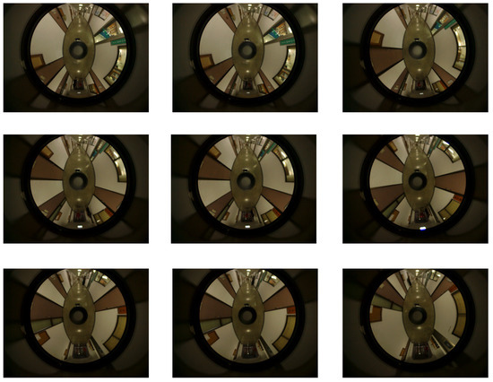
Figure 12.
The omnidirectional images used for the mobile robot localization in the second experiment. The images were captured when the mobile moved on non-smooth ground to evaluate the self-localization capability.
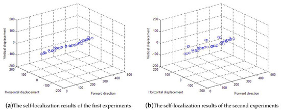
Figure 13.
The localization results of the experiments. The mobile robot moved on smooth and non-smooth ground for the first and second experiments, respectively. The blue dot represents the localization of the mobile robot in the environment. It consists of the forward, horizontal and vertical displacements.
In our method, it is required to generate the virtual environment for robot self-localization. This is different from the conventional vision-based localization approaches which use only the acquired real images. Thus, there is no easy way to compare our method with other algorithms using public image datasets. Nevertheless, we are able to run in real-time because of more restricted feature extraction and matching associated with the virtual environment. Due to the use of horizontal and vertical line features separately for the location computation, the accuracy in the horizontal direction is better than the altitude direction. This is because the feature points used for vertical lines span a fairly large range compared to the horizontal lines. Consequently, it affects the accuracy and possibly the stability of the final result. For the trade-off between our method and conventional vision based techniques, there is extra work to create the virtual environment. However, the geometric constraint enforced by the virtual space will keep the error in a certain range. It can avoid the accumulation of the drifting errors commonly seen in other localization methods.
6. Conclusions and Future Work
In this paper, we presented a vision-based self-localization technique for mobile robot navigation through a simulated virtual environment. The mobile robot’s position is calculated in the computer generated environment by the image feature matching with the real world scenes. Our proposed technique utilizes an omnidirectional camera to capture the images of the surroundings and estimate the camera motion trajectory based on the catadioptric projection model. Differently from the existing works using the omnidirectional images directly, our approach creates a parallel virtual space which simulates the environment in the real world. A mobile robot navigating along a trajectory was used to evaluate the proposed localization technique.
In the future work, a performance evaluation will be carried out in terms of the localization accuracy. The ground-truth positions of the mobile robot will be derived using a predefined path for comparison. Alternatively, other vision-based localization algorithms could be executed in parallel with the proposed technique for evaluation. Nevertheless, the input image sequence does not necessary have to be acquired from an omnidirectional camera. It could be monocular or a stereo image sequence captured from conventional perspective cameras. Another important issue for future investigation is the localization errors exclusively caused by the modeling of the virtual environment. More specifically, one should know the extent to which the localization accuracy is damaged if an incomplete or imprecise virtual model is provided.
Author Contributions
Conceptualization, H.-Y.L.; methodology, H.-Y.L.; software, C.-H.H.; validation, H.-Y.L. and C.-H.H.; formal analysis, H.-Y.L. and C.-H.H.; investigation, H.-Y.L.; resources, H.-Y.L.; data curation, C.-H.H.; writing—original draft preparation, H.-Y.L. and C.-H.H.; writing—review and editing, H.-Y.L.; visualization, C.-H.H.; supervision, H.-Y.L.; project administration, H.-Y.L.; funding acquisition, H.-Y.L. All authors have read and agreed to the published version of the manuscript.
Funding
The support of this work in part by the Ministry of Science and Technology of Taiwan under grant MOST 106-2221-E-194-004 and the Advanced Institute of Manufacturing with High-tech Innovations (AIM-HI) from The Featured Areas Research Center Program within the framework of the Higher Education Sprout Project by the Ministry of Education (MOE) in Taiwan is gratefully acknowledged.
Institutional Review Board Statement
Not applicable.
Informed Consent Statement
Not applicable.
Acknowledgments
The authors would like to thank the anonymous reviewers for their valuable suggestions.
Conflicts of Interest
The authors declare no conflict of interest.
References
- Kowadlo, G.; Russell, R.A. Robot odor localization: A taxonomy and survey. Int. J. Robot. Res. 2008, 27, 869–894. [Google Scholar] [CrossRef]
- Guidi, F.; Guerra, A.; Dardari, D. Personal Mobile Radars with Millimeter-Wave Massive Arrays for Indoor Mapping. IEEE Trans. Mob. Comput. 2016, 15, 1471–1484. [Google Scholar] [CrossRef]
- Barneto, C.B.; Rastorgueva-Foi, E.; Keskin, M.F.; Riihonen, T.; Turunen, M.; Talvitie, J.; Wymeersch, H.; Valkama, M. Radio-based Sensing and Environment Mapping in Millimeter-Wave 5G and Beyond Networks. arXiv 2021, arXiv:2102.11593. [Google Scholar]
- Lee-Johnson, C.P.; Carnegie, D.A. Mobile robot navigation modulated by artificial emotions. Syst. Man Cybern. Part Cybern. IEEE Trans. 2010, 40, 469–480. [Google Scholar] [CrossRef] [PubMed]
- Kim, T.H.; Choi, S.H.; Kim, J.H. Incorporation of a software robot anda mobile robot using a middle layer. Syst. Man Cybern. Part Appl. Rev. IEEE Trans. 2007, 37, 1342–1348. [Google Scholar] [CrossRef]
- Menegatti, E.; Pretto, A.; Scarpa, A.; Pagello, E. Omnidirectional vision scan matching for robot localization in dynamic environments. Robot. IEEE Trans. 2006, 22, 523–535. [Google Scholar] [CrossRef]
- Kramer, J.; Kandel, A. Robust small robot localization from highly uncertain sensors. Syst. Man Cybern. Part Appl. Rev. IEEE Trans. 2011, 41, 509–519. [Google Scholar] [CrossRef]
- Grewal, M.S.; Weill, L.R.; Andrews, A.P. Global Positioning Systems, Inertial Navigation, and Integration; John Wiley & Sons: Hoboken, NJ, USA, 2007. [Google Scholar]
- Kalman, R.E. A new approach to linear filtering and prediction problems. J. Basic Eng. 1960, 82, 35–45. [Google Scholar] [CrossRef]
- Do, C.H.; Lin, H.Y. Incorporating Neuro-Fuzzy with Extended Kalman Filter for Simultaneous Localization and Mapping. Int. J. Adv. Robot. Syst. 2019, 16, 1–13. [Google Scholar] [CrossRef]
- Roshany-Yamchi, S.; Cychowski, M.; Negenborn, R.R.; De Schutter, B.; Delaney, K.; Connell, J. Kalman Filter-Based Distributed Predictive Control of Large-Scale Multi-Rate Systems: Application to Power Networks. IEEE Trans. Control Syst. Technol. 2013, 21, 27–39. [Google Scholar] [CrossRef]
- Ledergerber, A.; Hamer, M.; D’Andrea, R. A robot self-localization system using one-way ultra-wideband communication. In Proceedings of the 2015 IEEE/RSJ International Conference on Intelligent Robots and Systems (IROS), Hamburg, Germany, 28 September–2 October 2015; pp. 3131–3137. [Google Scholar] [CrossRef]
- Zhang, Z. Iterative point matching for registration of free-form curves and surfaces. Int. J. Comput. Vis. 1994, 13, 119–152. [Google Scholar] [CrossRef]
- Izadi, S.; Kim, D.; Hilliges, O.; Molyneaux, D.; Newcombe, R.; Kohli, P.; Shotton, J.; Hodges, S.; Freeman, D.; Davison, A.; et al. KinectFusion: Real-time 3D reconstruction and interaction using a moving depth camera. In Proceedings of the 24th Annual ACM Symposium on User Interface Software and Technology, Santa Barbara, CA, USA, 16–19 October 2011; pp. 559–568. [Google Scholar]
- Vasile, A.N.; Skelly, L.J.; Ni, K.; Heinrichs, R.; Camps, O. Efficient city-sized 3D reconstruction from ultra-high resolution aerial and ground video imagery. In Advances in Visual Computing; Springer: Berlin, Germany, 2011; pp. 347–358. [Google Scholar]
- Salvi, J.; Matabosch, C.; Fofi, D.; Forest, J. A review of recent range image registration methods with accuracy evaluation. Image Vis. Comput. 2007, 25, 578–596. [Google Scholar] [CrossRef]
- Gaspar, J.; Winters, N.; Santos-Victor, J. Vision-based navigation and environmental representations with an omnidirectional camera. IEEE Trans. Robot. Autom. 2000, 16, 890–898. [Google Scholar] [CrossRef]
- Tasaki, T.; Tokura, S.; Sonoura, T.; Ozaki, F.; Matsuhira, N. Mobile robot self-localization based on tracked scale and rotation invariant feature points by using an omnidirectional camera. In Proceedings of the 2010 IEEE/RSJ International Conference on Intelligent Robots and Systems, Taipei, Taiwan, 18–22 October 2010; pp. 5202–5207. [Google Scholar] [CrossRef]
- Kawanishi, R.; Yamashita, A.; Kaneko, T.; Asama, H. Line-based camera movement estimation by using parallel lines in omnidirectional video. In Proceedings of the 2012 IEEE International Conference on Robotics and Automation, Saint Paul, MN, USA, 14–18 May 2012; pp. 3573–3579. [Google Scholar] [CrossRef]
- Goto, S.; Yamashita, A.; Kawanishi, R.; Kaneko, T.; Asama, H. 3D environment measurement using binocular stereo and motion stereo by mobile robot with omnidirectional stereo camera. In Proceedings of the 2011 IEEE International Conference on Computer Vision Workshops (ICCV Workshops), Barcelona, Spain, 6–13 November 2011; pp. 296–303. [Google Scholar] [CrossRef]
- Zhang, Z. Flexible camera calibration by viewing a plane from unknown orientations. In Proceedings of the Seventh IEEE International Conference on Computer Vision, Kerkyra, Greece, 20–27 September 1999; Volume 1, pp. 666–673. [Google Scholar]
- Scaramuzza, D.; Martinelli, A.; Siegwart, R. A flexible technique for accurate omnidirectional camera calibration and structure from motion. In Proceedings of the Computer Vision Systems, 2006 ICVS’06, New York, NY, USA, 4–7 January 2006; p. 45. [Google Scholar]
- Mei, C.; Rives, P. Single view point omnidirectional camera calibration from planar grids. In Proceedings of the Robotics and Automation, Rome, Italy, 10–14 April 2007; pp. 3945–3950. [Google Scholar]
- Geyer, C.; Daniilidis, K. A unifying theory for central panoramic systems and practical implications. In Computer Vision—ECCV 2000; Springer: Berlin, Germany, 2000; pp. 445–461. [Google Scholar]
- Barreto, J.P.; Araujo, H. Issues on the geometry of central catadioptric image formation. In Proceedings of the Computer Vision and Pattern Recognition, Kauai, HI, USA, 8–14 December 2001; Volume 2. [Google Scholar]
- Ansar, A.; Daniilidis, K. Linear pose estimation from points or lines. IEEE Trans. Pattern Anal. Mach. Intell. 2003, 25, 578–589. [Google Scholar] [CrossRef]
- Hartley, R.I.; Kahl, F. Global optimization through rotation space search. Int. J. Comput. Vis. 2009, 82, 64–79. [Google Scholar] [CrossRef]
- Lepetit, V.; Moreno-Noguer, F.; Fua, P. Epnp: An accurate o (n) solution to the pnp problem. Int. J. Comput. Vis. 2009, 81, 155–166. [Google Scholar] [CrossRef]
- Horn, B.K.; Hilden, H.M.; Negahdaripour, S. Closed-form solution of absolute orientation using orthonormal matrices. JOSA A 1988, 5, 1127–1135. [Google Scholar] [CrossRef]
Publisher’s Note: MDPI stays neutral with regard to jurisdictional claims in published maps and institutional affiliations. |
© 2021 by the authors. Licensee MDPI, Basel, Switzerland. This article is an open access article distributed under the terms and conditions of the Creative Commons Attribution (CC BY) license (https://creativecommons.org/licenses/by/4.0/).