Article

Design of External Rotor Ferrite-Assisted Synchronous Reluctance Motor for High Power Density

1
Tula Technology Inc., 2460 Zanker Road, San Jose, CA 95131, USA
2
Electrical & Computer Engineering, Mississippi University, 406 Hardy Road, Simrall 216, Mississippi State, MS 39762, USA
3
Electrical & Computer Engineering, The University of Akron, 302 Buchtel Common, Akron, OH 44325, USA
4
Electrical Engineering & Computer Science, University of Cincinnati, 2600 Clifton Ave., Cincinnati, OH 45221, USA
5
Advanced Engineering, Electrification, Cummins Power Generation, Corp. R&T, 1400 73rd Ave, Fridley, MN 55432, USA
6
Electrical & Electronics and Communication Engineering Department, Koreatech University, Cheonan-si 31253, Korea
*
Author to whom correspondence should be addressed.
Appl. Sci. 2021, 11(7), 3102; https://doi.org/10.3390/app11073102
Submission received: 20 February 2021 / Revised: 26 March 2021 / Accepted: 28 March 2021 / Published: 31 March 2021
(This article belongs to the Special Issue Design and Analysis of Electrical Machines and Drives)

Abstract

:
The rare-earth (RE) permanent magnets (PM) have been increasingly adopted in traction motor application. However, the RE PM is expensive, less abundant, and has cost uncertainties due to limited market suppliers. This paper presents a new design of a RE-free five-phase ferrite permanent magnet-assisted synchronous reluctance motor (Fe-PMaSynRM) with the external rotor architecture with a high saliency ratio. In such architecture, the low magnetic coercivity and demagnetization risk of the ferrite PM is the challenge. This limits the number of flux barriers, saliency ratio, and reluctance torque. A precise analytical design procedure of rotor and stator configuration is presented with differential evolution numerical optimizations by utilizing a lumped parameter model. A 3.7 kW prototype is fabricated to validate the proposed idea.

1. Introduction

High torque density traction motors have been designed with rare-earth material alloys such as neodymium-ferrite-boron (Nd2Fe14B), samarium-cobalt (Sm-Co), and dysprosium-ferrite-boron (Dy2Fe14B) [1,2,3,4]. However, they are costly. Low-cost ferrite permanent magnets (Fe-PM) such as Y30 and Y32H grades PMs have been considered alternative options in the industry [4,5]. Various design approaches have been suggested to increase the torque and power density, such as multi-phase windings, outer rotor structure, salient type rotors, spoke-PM rotor, and transverse flux topology [6,7,8,9,10]. However, maintaining high torque density while ensuring demagnetization-free operations has been challenging until recently due to Fe’s low coercive force and low energy density.
For example, interior permanent magnet (IPM) machines with rare-earth magnets have been utilized in tractions motor application [4,11,12]. However, the cost of RE PM is expensive (>30% of overall cost). Instead, Fe-PMaSynRM can offer low-cost, better constant power-speed range, and comparable torque density compared to RE-PM-based IPM [13,14,15]. Thus, extensive research has been conducted on Fe-PMaSynRM to achieve high torque density, torque ripple, risk of irreversible demagnetization and mechanical deformation [6,16,17,18].
To further achieve higher power density, an external rotor electric motors could be a strong candidate. Depending on the optimal split ratio (ratio of stator outer diameter to rotor outer diameter) and relatively high bore diameters, an external rotor motor can offer significantly higher torque density compared to the internal rotor system [19,20]. Also, the external rotor motors are suitable for direct-drive in-wheel applications and can save drive space with integrated drive electronics [21,22,23,24,25]. To utilize such advantages, in [26], a three-phase external rotor Fe-PMaSynRM has been proposed as a low-cost but high-power density motor in an electric two-wheeler. The fault-tolerant multi-phase (number of phase > 3) external rotor designs have also been proposed, such as five-phase ferrite-based IPM and five-phase Fe-PMaSynRM [27,28]. It has been observed that the additional phases not only boost the fault-tolerance but also increase the torque density compared to three-phase motors. In [29], performance comparisons between five-phase RE-PM-based and RE-free external rotor PMaSynRM are presented. The RE-free design has shown comparable torque density to the RE-PM-based design at lower material costs. In [28], multi-physics analysis design optimization of external rotor PMaSynRM has been presented that considers the developed heat transfer and mechanical stress. In [30], the authors have discussed the torque ripple reduction approach for the same motor by using rotor surface notch. However, articles [28,29,30] have focused on some major and common concerns of external rotor PMaSynRM such as heat extraction, torque ripple reduction, and torque density increasing. The demagnetization aspects of the Ferrite PM, which are a major concern for using Ferrite-PM in external rotor PMaSynRM design, have not been discussed in detail.
This paper presents the precise design procedures of a five-phase external rotor Fe-PMaSynRM for high torque density applications. Detailed design considerations such as optimal rotor and stator configurations and geometrical parameters to maintain high torque density and low torque ripple while ensuring demagnetization-free operation have been presented in detail. The proposed RE-free motor has been compared to a benchmark external rotor RE-PMaSynRM with the same outer dimensions to validate the torque density. Section 2 shows the design considerations for high power density and illustrates the risk of irreversible demagnetization. Section 3 presents the design optimization procedures for the optimal five-phase outer rotor Fe-PMaSynRM. In Section 4, the finite element analysis (FEA) simulation results are presented to compare the proposed external rotor Fe-PMaSynRM and benchmark external rotor RE-PMaSynRM. Finally, in Section 5, experimental validations are provided through tests on the proposed 3.7 kW external rotor Fe-PMaSynRM prototype.

2. Challenges and Design Considerations for High Power Density External Rotor Fe-PMaSyn RM

This section discusses the considerations and challenges in designing external rotor Fe-PMaSynRM and the risk of irreversible demagnetization. For the pictorial introduction, an internal rotor and an external rotor PMaSynRM are shown in Figure 1a,b, respectively.
Both motors have the same slot-pole configuration, same number of flux barriers per pole, same outer diameter, and different bore diameters. In the external rotor PMaSynRM, as the flux barriers are at a higher radial distance, the flux barrier length and permeance values are usually higher than the internal rotor counterpart. This will influence the reluctance profile, saliency ratio, and create room for more magnet composition, impacting the generated reluctance torque, PM-torque, and anti-demagnetization ability of the motor.

2.1. Concerns with Reluctance Torque Portion in High Power Density External Rotor PMaSynRM

The volume power density Pv of external rotor Fe-PMaSynRM, defined as the developed output power over the motor volume, can be expressed as follows:
P v = T e m   ω m π   r r o 2   L    
Tem is developed electromagnetic torque, ωm is the rotor’s mechanical angular speed, L is the motor’s axial length, and rro is the rotor’s outer radius (which is also the outer radius of the motor). According to (1), for a fixed motor volume and fixed rotor speed, the volume power density of the motor (Pv) is proportional to the developed electromagnetic torque (Tem). For a five-phase PMaSynRM, the average torque Tem can be written as follows: [30]
T e m = T P M + T r e l u c t a n c e = 5 2   p   λ P M   I d + 5 2   p   λ P M   I d ( L d L q   1 ) L q   L d   I q  
where TPM is developed electromagnetic torque due to the PM, Treluctance is the developed electromagnetic torque due to rotor saliency, λPM is the permanent magnet flux linkage, p is the number of pole pairs, and Ld, Lq, Id, and Iq are the d- and q-axis inductances and currents, respectively. The reluctance torque is largely dependent on the saliency ratio (Ld/Lq), whereas the PM-torque is dependent on the permanent magnet flux linkage. The torque equation in (2) can be extended as follows:
T e m = π 4   B P M 1   K d   D 2   L + π 4 ( B d 1   K q B q 1   K d ) D 2 L  
Kd and Kq are the d- and q-axis current density, BPM1, Bd1, and Bq1 are the fundamental of air-gap flux density due to PM, d-axis current, and q-axis current, respectively.
According to (3), the developed torque in Fe-PMaSynRM increases in proportion to the bore diameter (D) square while the other terms are constant. To obtain higher torque in external rotor PMaSynRM, if the bore diameter (D) increases while the BPM1, and L are maintained constant by keeping almost the same dimension of the PM, then the PM-torque will increase with D2. However, the increase of D will hurt the reluctance torque component. The increased bore diameter increases the d-axis equivalent circuit reluctances due to decreased width and increased length of the d-axis flux path, which will decrease Bd1. Simultaneously, the q-axis equivalent circuit’s reluctances decrease as the q-axis flux paths become wider with increased D, which will increase Bq1. Therefore, the increase of bore diameter (D) in external rotor PMaSynRM might decrease the value of (Bd1Kq-Bq1Kd) and limit the reluctance torque. Overall, a higher bore diameter (D) in the external rotor motor tends to increase the PM-torque and decrease the reluctance torque. The design objective is to achieve higher average torque with a significant proportion of reluctance torque.

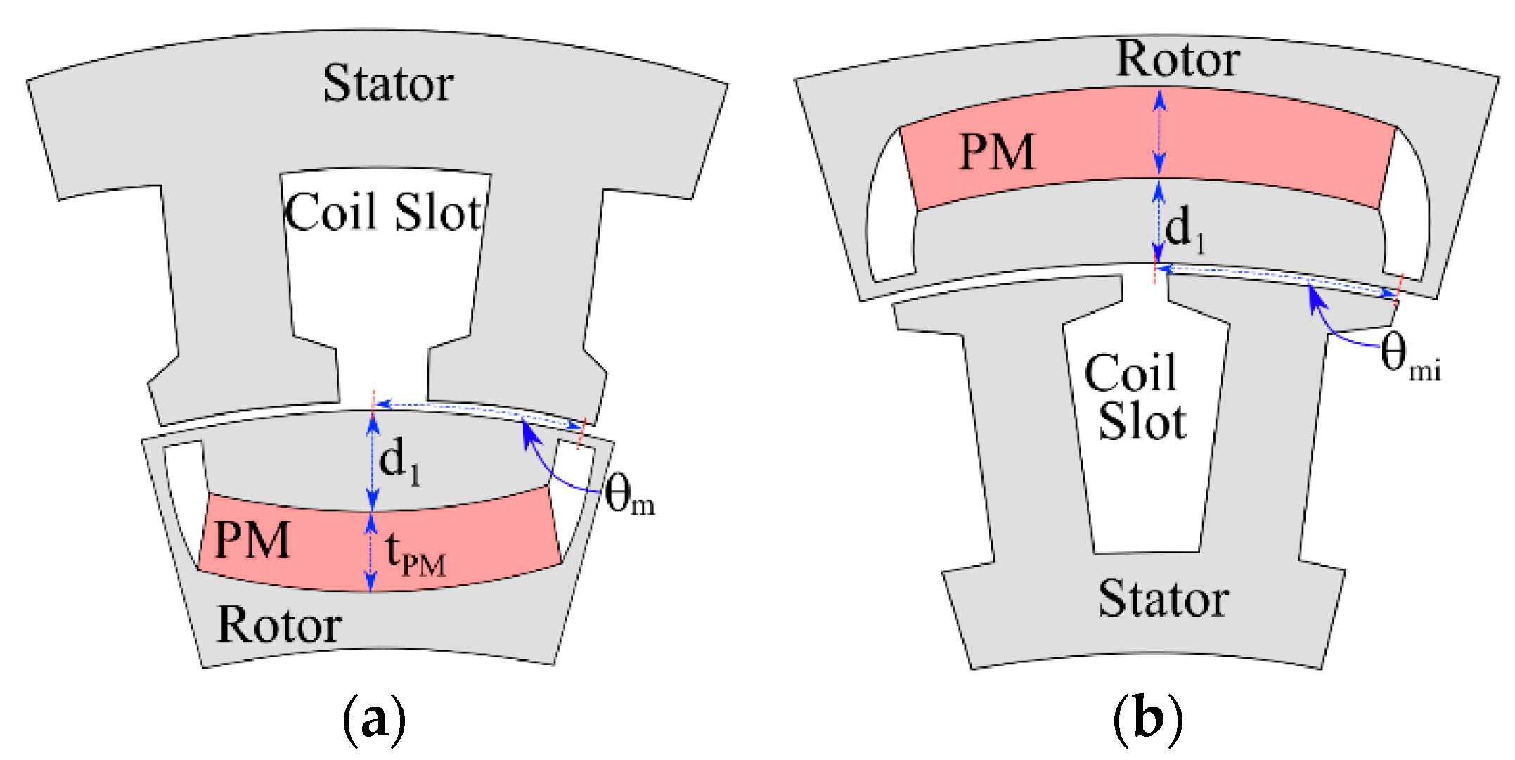
2.2. Demagnetization Concerns with External Rotor Structure

The risk of irreversible demagnetization is a significant concern for any Fe-PM motor. This can be a more significant concern in external rotor Fe-PMaSynRM with higher torque density and increased bore diameter. Figure 2a,b show a single-pole structure of an internal rotor Fe-PMaSynRM and an external rotor Fe-PMaSynRM, respectively.
Both motors are assumed to have the same outer dimensions, arc-shaped Fe-PM with the same angular span, and a single flux barrier per pole. However, the external rotor motor’s bore diameter is higher to obtain higher average torque (D external rotor > D internal rotor). Then the PM-thickness will tend to be smaller in the outer rotor motor. This will impact the operating flux density of the Fe-PM, which can be expressed as:
B m , j = B r e m Δ f r , i   μ t m , i  
where tm,i is the thickness of magnet in the i-th flux barrier, Brem is the magnet remnant flux density, μ is the magnet permeability, Bm,i is magnetic flux density in the i-th flux barrier, and Δfr,i is the rotor magnetic potential difference across i-th flux barrier. Equation (4) applies to both internal and external rotor PMaSynRM. Here, the Brem and μ are constant for a specific magnet at a given temperature. Also, at a specific temperature, the knee point flux density is constant for a specific magnet. Hence, according to (4), the maximum limit of the applied demagnetizing field is directly related to the magnet thickness (tm).
Overall, if the bore diameter (D) is increased in the external rotor motor for high power density, it might have two significant consequences. The first one is the reduction of reluctance torque, and the second one is the increased susceptibility to demagnetization. The reduction of reluctance torque will reduce the benefit of PMaSynRM, while the increased susceptibility to demagnetization will limit the electric overloading capability and fault tolerance. Usually, any motor is designed to withstand certain electric overloading conditions, while the five-phase motors are designed to withstand open-phase fault operation toward generating a specific average torque. Hence, the primary design challenges and design objectives for high power density external rotor five-phase Fe-PMaSynRM are achieving higher average torque with significant reluctance torque portion and ensuring high anti-demagnetization ability. Detailed discussion on the motor configuration, optimal flux barrier shaping, and parameter optimization are presented.

3. Design of Fe-PMaSynRM for High Power Density

This section describes the design procedure of the five-phase external rotor Fe-PMaSynRM for generating high power density. Two primary objectives are considered: (1) achieving higher average torque and (2) ensuring the robustness in terms of anti-demagnetizing ability. The flux barrier design, slot-pole configuration, and design parameters optimization will be discussed. Figure 3 shows the design parameters of a five-phase external rotor Fe-PMaSynRM mapped on a single pole.

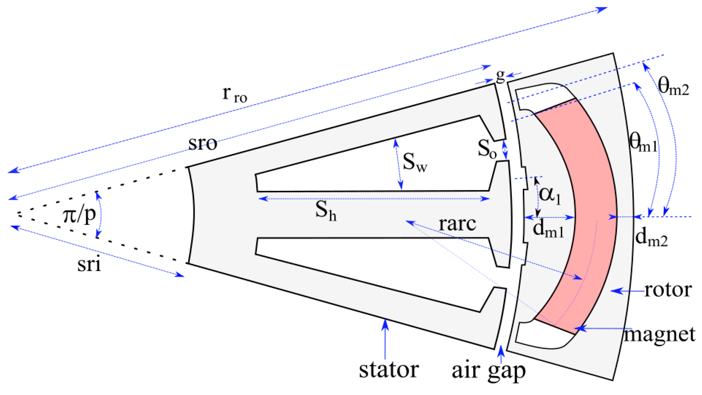
3.1. The Designs of Flux Barrier

The rotor of external rotor PMaSynRM resembles a thick-walled hollow cylinder where each pole is an arc of angle 180/p degree (shown in Figure 3) and thickness (rro-g-sro). The U-shaped flux barrier with an arc-shaped magnet will be a suitable selection for this type of pole piece [31]. The flux barrier shape and thickness will influence the PM-surface area and reluctance profile. It has been shown that the PM-surface area and reluctance profile will determine the fundamental air-gap flux density due to PM (BPM1), and developed torque due to permanent magnet [32]. For an arc-shaped magnet in the U-shaped flux barrier, the surface area of the magnet can be expressed as:
A P M , i = L   r a r c , i   θ a r c , i = 2   L   r a r c , i   s i n 1 ( D / 2 r a r c , i   s i n θ m , i 2   )  
where θmi is the PM angle on the center (shown in Figure 3), θarc,i is the PM angle on the center of PM-arc, rarc,i is the radius of the PM-arc (shown in Figure 4).

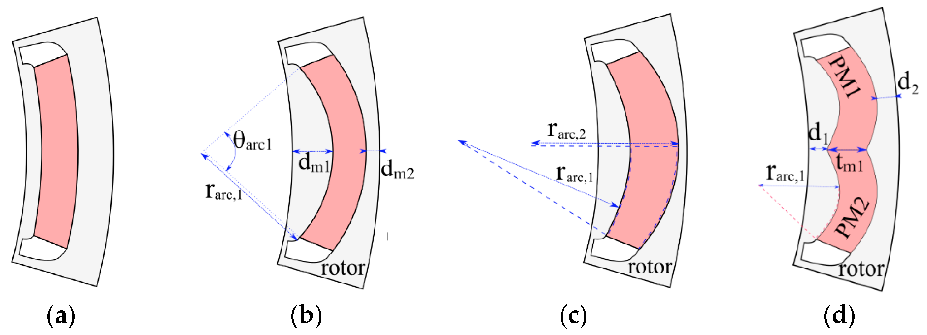
3.1.1. Varying Degree of Curvature Arc-shaped PM

If the degree of curvature of the PM is varied then its effective surface area will vary according to (5). Figure 4 shows several arc-shaped PM-based flux barrier designs. For the design in Figure 4a, the PM-surfaces are parallel to the rotor surfaces. In this design, the PM-surface will be minimum (mi). The design in Figure 4b shows uniformly thick PM with a low PM-arc radius. It can be shown that for the variation of the curvature degree represented by rarci equal (D/2 + d1) to mi/2, the PM-surface will increase up to π/2 times. The design in Figure 4c shows tapered PM, which effectively eliminates partial demagnetization in the middle of the arc-shaped PM. Figure 4d shows two different arc-shaped are used in one flux barrier to increasing the PM-surface area. This design also reduces the flux barrier’s radial span, effectively reducing the outer rotor diameter for the same average torque.

3.1.2. Variation Developed Torque and Anti-Demagnetization Ability with PM-Shape

The curvature (rarc) degree will influence the motor’s average torque. To show the effect of rarc on the developed torque and anti-demagnetization ability, an FEA model of the proposed motor specified in Table 2 has been taken as the base model. Then rarc is varied in a certain rage to record the average torque (Tavg) and maximum allowable q-axis current (iq,irr). Figure 5a shows the variation of average torque with changes of rarc. With the decrease of the radius of the magnet surface (rarc), the surface area of the magnet increases for the same magnet span (θm) and magnet depth from the rotor surface (dm), which will increase the average torque Tavg. Simultaneously, the allowable maximum q-axis without irreversible demagnetization will be impacted due to a change in rarc. Figure 5b shows the changes in allowable maximum q-axis circuit current (Iq,irr) vs. degree of curvature of the PM, rarc. Overall, with the higher degree of curvature of the magnet (lower rarc), average torque reduces, and maximum allowable q-axis current (Iq,irr) increases.

3.2. Magnetic Equivalent Circuit-Based Analytical Model

A lumped-parameter model (LPM) has been developed to analytically calculate the electromagnetic performance of the external rotor Fe-PMaSynRM. The LPM uses the d- and q-axis equivalent magnetic circuit (EMC) components to calculate d- and q-axis inductances. The EMC components of the external rotor Fe-PMaSynRM are shown in Figure 6. The q-axis EMC is mapped on the simplified rotor architecture of three-flux barrier per pole design in Figure 6. The d- and q-axis EMC for single-flux barrier per pole structure is shown in Figure 7a,b, respectively. Table 1 depicts the EMC parameters, which have been utilized to develop d- and q-axis circuits shown in Figure 6 and Figure 7. It has been shown that the saturation effect needs to be in the d-axis EMC and can be ignored in q-axis EMC [32]. The dimensional parameters in Figure 3 can be used to obtain the reluctances in d- and q-axis EMC [33].

3.3. Optimization Algorithm

A multi-objective optimization algorithm has been adopted to extract an optimal external rotor PMaSynRM design with a high power density and low torque ripple. It has been shown that the differential evolution (DE) algorithm can be applied to solve the multi-objective motor design optimization with a finite number of constraints [27]. In this study, Equation (6) is the multi-objective optimization function that has been utilized to obtain the optimal external rotor PMaSynRM design with a high power density and low torque ripple.
O F = k 1   η 2 + k 2   T e m 2 + k 3   ( 1 / T r ) 2  
k1, k2, and k3 are the weighting factors set to obtain optimal design with respect to high efficiency, average torque, and low torque ripple. k1 is set to 0.3, k2 is set to 0.4, and k3 set to 0.4. The objectives and constraints considered during design optimization are as follows:
(1)
maximum torque > 18 Nm
(2)
minimum torque ripple < 5%
(3)
input current < 15 A rms
(4)
Eloss < 5% of input power
(5)
rotor outer diameter = 190 mm
(6)
rotor speed = 1800 rpm
(7)
ratio of maximum reluctance torque to total torque > 0.3
A set of 50 candidate solutions are populated in each iteration of the DE algorithm. Computation effort is one of the crucial factors in the DE optimization procedure. 20 iterations have been carried out in 136 min to generate the 50 final optimal solutions, which solve the multi-objective optimization function. Among the 50 optimal solutions, only one of the designs is selected based on the manufacturing feasibility. The flow diagram to obtain the final design proposed in this study is shown in Figure 8. The following subsections discuss the final optimal solution.

3.4. Optimal Design Variables

The converged values of the design variables are shown in Table 2. The design variables include the slot/pole combination, split ratio, and several other dimensional parameters. The optimal value of the split ratio was found to be 0.82 for the proposed model. The selection of optimal slots/pole combination is another critical step toward designing a high power density motor. The slot/pole combination is related to the MMF harmonics components generated by the windings and defines whether the winding is of distributed or concentrated type. The differential evolution algorithm generates different random designs with different slot/pole combination. The LPM tool calculates the motor performance by finding saliency ratio, torque, and losses while the obtained optimal winding configuration is a distributed winding with coil span 2 which has 25 slots and 12 poles, as given in Table 2. Although, for in-wheel applications, the concentrated windings are more suitable owing to the very low space required for their end winding, they offer lower saliency ratio and higher copper loss. Hence, the distributed winding has been found as an optimal one due to their higher salient torque, lower torque ripple, and lower overall loss compared to the concentrated winding configurations. In fact, the coil span is comparatively lower than the conventional distributed winding machines which ensures less space taken by the end winding and less coil overlapping. Considering the MMF harmonics for different slot/pole configuration, the differential evolution algorithm-based design optimization saves the best design and discards the poor ones.

3.5. Multi-Physics Analysis

Multi-physics simulations are conducted to ensure acceptable electromagnetic performance, thermal and structural sustainability. The optimal model with the optimization mentioned in the above process has been exported to the FEA tools for thorough electromagnetic, thermal, and structural analysis. The results and corresponding design changes are discussed in the following sub-subsections.

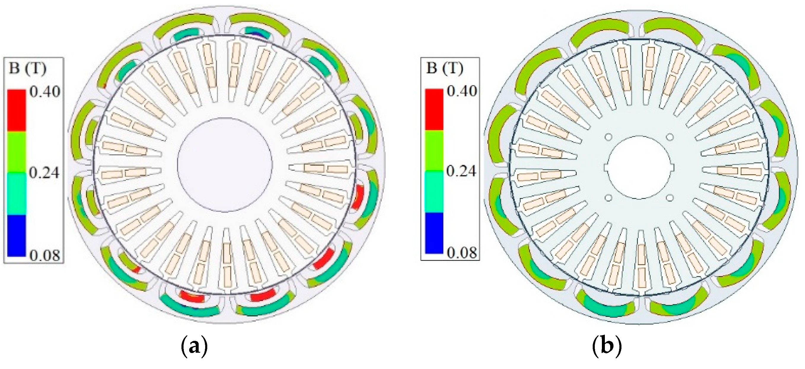
3.5.1. Flux Density under No-Load and Rated Load

At first, the optimal motor’s FEA model is simulated for different current loadings. The flux density levels in the rotor and stator components are observed to determine the core saturation. If the core’s flux density levels are significantly high at the rotor and stator yokes, stator teeth, and air-gap, then the design is discarded to avoid higher core losses and poor performance. The simulation results of flux density in the core underrated current excitation for the optimal two and single flux barrier design are shown in Figure 9a,b, respectively. Both designs show an acceptable level of saturation under rated excitations.

3.5.2. Flux Density under Demagnetizing Field

The q-axis circuit (Iq) current is associated with the demagnetization. The motor is simulated for different Iq currents to observe irreversible demagnetization, and magnet-flux densities are observed. Optimizing the number of mesh and number of points in the magnet for demagnetization observation is very important for estimating and calculating time. For the proposed motor, the calculation accuracy was obtained for maximum mesh size 1 mm inside the magnet, 1.5 mm inside the core, and 1 mm on the stator’s inner surface. A total of 200 uniformly distributed points were considered in the magnet to observe flux density levels and identify whether the partial demagnetization has occurred or not. The magnets’ flux density levels were observed at 2.5 times rated RMS current flown through the q-axis circuit. If any PM’s flux density reduces below the knee point, then the design is considered weaker against demagnetization, and the optimal model is discarded. Figure 10a shows the magnet-flux densities in two flux barrier designs, and Figure 10b shows the magnet-flux densities in the single flux barrier design. The simulation results show the magnets in both upper and lower flux barriers of the two flux barrier design will be partially demagnetized. In contrast, the single flux barrier design was demagnetization proof under the above mentioned worst demagnetizing criteria.

3.5.3. The Decision on Rotor Configuration Based on Electromagnetic Analysis

The multi-physics analysis results have been considered. The flux barriers create the rotor saliency as well as house the Fe-PM. As discussed before, the flux barrier thickness and their numbers in each pole influence the average torque and the demagnetization characteristics. The thickness of the flux barriers (tm), angular span (θm1), and magnet span (θm2) have been optimized using the LPM and DE, as shown in Table 3 Initially, several design variables such as flux barrier number, shape, and dimensions are considered during the optimization. The DE algorithm and multi-physics analysis combined helped narrow the flux barrier number to two, which is subjected to the constraints and multi-objective cost function. The FEA simulation is then conducted on the optimal model to ensure proper saturation in the core and robustness against demagnetization. Based on the FEA results, specified torque were obtained, however, the demagnetization characteristics were not satisfied as the magnets were getting partially demagnetized at 2.5 times rated RMS current flown through the q-axis circuit. Therefore, the LPM model was modified for two flux-barrier-based design and DE optimization has been conducted to find the optimal model. The single flux barrier design met the demagnetization criteria of withstanding 2.5 times of rated current flown through the q-axis circuit. The LPM model has been modified for the single flux barrier design and optimized. The multi-physics simulation of the single flux barrier design shows that it can withstand the maximum demagnetizing field of 2.5 times the rated current.

4. Finite Element Simulations

Extensive finite element simulations have been carried out to evaluate the performance of the proposed external rotor Fe-PMaSynRM. This section shows whether the proposed motor meets the key challenges such as the specified torque, reluctance torque proportion, and anti-demagnetization ability. The results have been compared with the corresponding results from the external rotor RE-PMaSynRM.

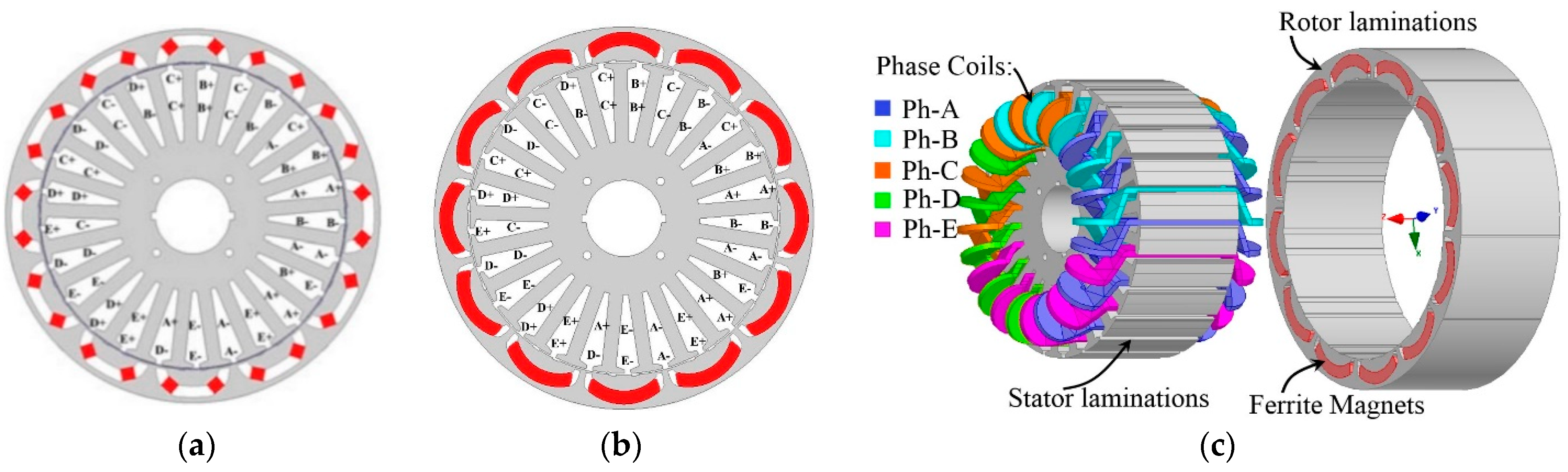
4.1. FEA Models of the Optimal Designs

The FEA models of the optimal designs are given in Figure 10. The benchmark five-phase external rotor RE-PMaSynRM is presented in Figure 11a, optimized for higher efficiency and low torque ripple to fit in-vehicle applications [30].
The 2D cross-section of the proposed external rotor Fe-PMaSynRM is shown in Figure 11b. Its 3D exploded view is shown in Figure 11c. The specifications of both machines are provided in Table 3.

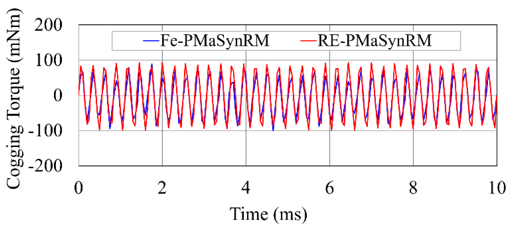
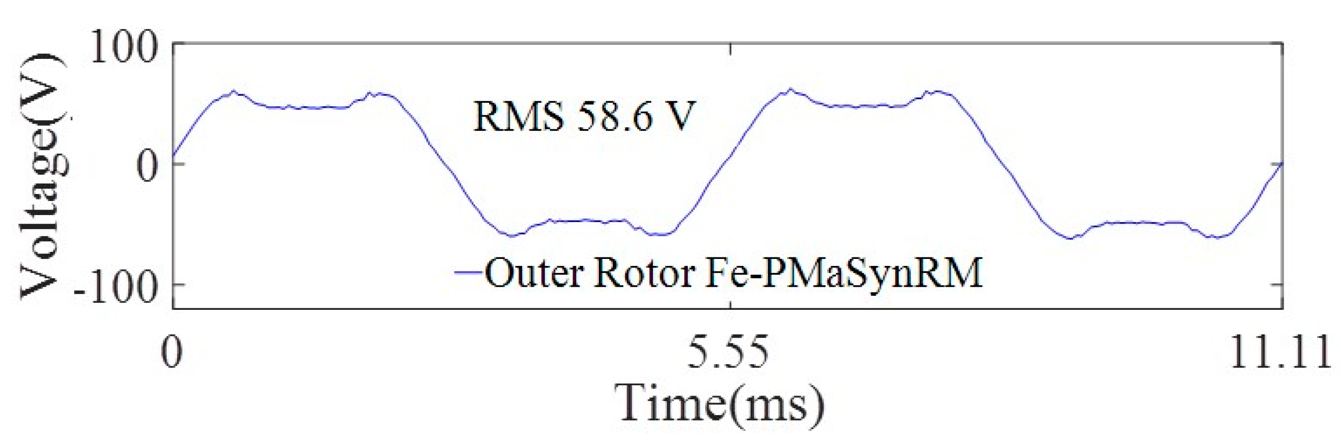
4.2. Cogging Torque and Back-EMF under No-Load

The developed cogging torques in the proposed ferrite PM-based external rotor motor and rare-earth PM-based motor are shown in Figure 12. The result shows that under no load and at 1800 rpm rotor speed, the peak-to-peak cogging torque developed in the proposed Fe-PMaSynRM design is around 0.2 Nm, which is nearly the same in the RE-PMaSynRM. Therefore, both motors will develop comparable torque pulsation at no load, which is nearly 1% (peak-to-peak) of the average torque.
The back-emfs of the proposed rare-earth free and rare-earth-based external rotor PMaSynRM are shown in Figure 13. The result shows the developed induced voltage in phase-A winding at 1800 rpm rotor speed. The RMS values of the phase back-EMFs in ferrite and neodymium-based external rotor PMaSynRMs are 63.7 and 47 V, respectively. The differences between the back-EMFs are significant differences in the remnant flux density and flux barrier shapes of Fe and Nd-based motors.

4.3. Developed Torque under Rated-Load

The machine has been simulated for different current ratings and the developed torque has been recorded. Figure 14 shows the developed torque in both external rotor RE-PMaSynRM and Fe-PMaSynRM machines under rated current and rated speed. The average value of the rated torque is 19.2 Nm in the proposed Fe-PMaSynRM, which is slightly higher (19.7 Nm) in the RE-PMaSynRM. The torque ripple in the proposed external rotor motor is 5% which is nearly same as the benchmark rare-earth magnet-based motor.

4.4. Anti-Demagnetization Ability Observation

FEA simulations have evaluated the ability of the motor to withstand a higher demagnetizing field. The results are provided in Figure 15, where the flux density levels are shown for different current loading conditions. Figure 15a shows magnet flux densities under no-load, and Figure 15b shows magnet flux densities under rated-load. In both cases, PM-flux density levels are well above the proposed ferrite magnet’s knee point flux density. The q-axis current component is responsible for creating the demagnetizing field across the magnets, and hence, the flux densities in the magnets for different values of q-axis current excitations are shown in Figure 15c,d. The magnetic flux density for q-axis current at two and three times the rated current is shown in Figure 15c,d, respectively. Figure 15d shows, under a q-axis current at three times the rated current, the flux density level in a PM is below the threshold level, which will cause permanent partial demagnetization of the magnet. This overloading condition will partially demagnetize all the ferrite magnets in the motor. The load and demagnetization curves are presented in Figure 15e. It shows the magnetization loss under demagnetizing Iq, (q-axis current) up to three times the rated current.

4.5. Summary of Design Comparisons

The performance comparison of the rare-earth-free and rare-earth-based PMaSynRMs has been summarized in Table 4.
The traction motors are often optimized to perform efficiently in several different drive-cycles [34]. These drive-cycles can be conveniently represented by several operating points during traction motor design and performance analysis [34]. The proposed five-phase external rotor Fe-PMaSynRM has been simulated at several operating points covering the motoring and generating regions. The FEA results consisting of losses and efficiencies are presented in Table 5.

5. Experimental Results

The proposed 3.7 kW five-phase external rotor Fe-PMaSynRM has been fabricated and tested to validate the torque generation and back-emf simulation results. The fabricated five-phase Fe-PMaSynRM is shown in Figure 16 where the stator laminations are shown in Figure 16a, rotor laminations are in Figure 16b. The stator has 25 slots, and the stator coils are distributed with a span of 2 slots. The rotor has 12 poles that are distinguishable by the arc-shaped Y32H-2 grade Fe magnets. Both stator and rotor cores contain 50PN600 steel to support the high torque density objective and to avoid the saturation. The weight of active materials of the initial model and optimal prototype Fe-PMaSynRM model have been shown in Table 6.
The fabricated Fe-PMaSynRM has been mounted on a 5 HP dynamo testbed to validate the design properties and support the high power density operation shown in Figure 17. The dynamo is built with a DC machine as the prime mover and a digital electronic load. The test setup is shown in Figure 17a and the controller block diagram to drive the motor is shown in Figure 17b An indirect field-oriented control method has been adopted. An in-house five-phase inverter has been developed. The control algorithm is developed and implemented in the digital signal processor (TI DSP F28335). As shown in Figure 17b the five-phase currents are sensed to transform it to 2D vector quantities namely d-q axes components. Conventional PI regulators were designed to perform the closed-loop control of d-q currents followed by inverse park-transformation and generation five-phase voltages at the output terminals of the voltage source inverter. Field-oriented control utilizing MTPA and FW strategies were chosen to conduct the tests.
First, no-load tests of the prototype are performed to observe the back-EMF and cogging torque. The back-EMF curve at 1800 rpm rotor speed has been shown in Figure 18. It is observed that the back-emf of the proposed Fe-PMaSynRM has a peak voltage of 62.75 V and an RMS voltage of 58.6 V, which nearly matches the FEA results shown in Figure 13. The cogging torque of the external rotor Fe-PMaSynRM is shown in Figure 19. To measure this quantity the Fe-PMaSynRM was connected to an induction machine which acted as the prime mover. The prime mover was spun at a speed of 2.5 Hz. A torque transducer was used on the shaft of the motor to capture the torque. It is observed that the peak-to-peak cogging torque of the proposed five-phase external rotor Fe-PMaSynRM is only 0.024 Nm, which was predicted to be 0.19 Nm as per FEA results. Although, the difference is significant, both values are reasonably small. The difference might have occurred from a reasonably small error in measured torque data of the dyno setup.
Second, experimental test for full excitation is also carried out on the fabricated prototype to compare the generated torque under load. During this test, the prime mover was running at rated speed of 1800. A vector control using MTPA algorithm was implemented to generate the maximum torque with minimum current. The torque was captured using torque transducer. A position sensor was utilized to get the rotor information utilizing an incremental encoder. Before the test, the optimal angle offset was calculated to ensure MTPA method. Figure 20a shows the output torque of the five-phase external rotor Fe-PMaSynRM. The test result shows the average torque developed under rated excitation by the five-phase external rotor Fe-PMaSynRM is 19.4 Nm. The predicted torque from the FEA data was 19.2 Nm which is very close to the test data.

6. Conclusions

Economical rare-earth-free Fe-PMaSynRM designs can be optimally designed to better the performance of traction motor designs. In this study, the optimal design of a rare-earth-free five-phase external rotor ferrite permanent magnet-assisted synchronous reluctance motor (Fe-PMaSynRM) has been presented. The anti-demagnetization ability has been a major focus during the design process during selecting the slot-pole configuration, flux barrier design to achieve low torque ripple, higher efficiency, and high average torque. Proposed 3.7 kW five-phase outer rotor Fe-PMaSynRM has shown competitive torque density to a rare-earth counterpart while withstanding 2.5 times of rated current without any signs of demagnetization. Optimal design has been fabricated and tested to validate the simulation results. Overall, the Fe-PMaSynRM proposed in this study can be considered as a rare-earth-free competitive design to the rare-earth-based traction motor designs.

Author Contributions

The literature review and manuscript preparation, as well as the simulations, were carried out by M.Z.I., S.S.R.B., and S.C. Experimental testing was conducted by A.A., and final review of manuscript corrections was done by M.E.E. and J.B. All authors have read and agreed to the published version of the manuscript.

Funding

This research was partially funded by the National Science Foundation Innovation Corps (I-Corps) Teams Program (Award Number: 1518968) for 1st and 2nd author. Also, this research was partially funded by grant (21RTRP-B146050-04) from Railroad Technology Research Program (RTRP) funded by Ministry of Land, Infrastructure and Transport of the Korean government for 3rd author.

Conflicts of Interest

The authors declare no conflict of interest.

References

  1. Lee, D.-K.; Ro, J.-S. Analysis and Design of a High-Performance Traction Motor for Heavy-Duty Vehicles. Energies 2020, 13, 3150. [Google Scholar] [CrossRef]
  2. Reddy, P.B.; El-Refaie, A.M.; Huh, K.K.; Tangudu, J.K.; Jahns, T.M. Comparison of interior and surface pm machines equipped with fractional-slot concentrated windings for hybrid traction applications. IEEE Trans. Ind. Electron. 2012, 27, 593–602. [Google Scholar] [CrossRef]
  3. Sarlioglu, B.; Morris, C.T.; Han, D.; Li, S. Driving Toward Accessibility: A Review of Technological Improvements for Electric Machines, Power Electronics, and Batteries for Electric and Hybrid Vehicles. IEEE Ind. Appl. Mag. 2017, 23, 14–25. [Google Scholar] [CrossRef]
  4. Jahns, T. Getting Rare-Earth Magnets Out of EV Traction Machines: A review of the many approaches being pursued to minimize or eliminate rare-earth magnets from future EV drivetrains. IEEE Electrif. Mag. 2017, 5, 6–18. [Google Scholar] [CrossRef]
  5. Boldea, I.; Tutelea, L.N.; Parsa, L.; Dorrell, D. Automotive Electric Propulsion Systems with Reduced or No Permanent Magnets: An Overview. IEEE Trans. Ind. Electron. 2014, 61, 5696–5711. [Google Scholar] [CrossRef]
  6. Yoon, K.-Y.; Baek, S.-W. Performance Improvement of Concentrated-Flux Type IPM PMSM Motor with Flared-Shape Magnet Arrangement. Appl. Sci. 2020, 10, 6061. [Google Scholar] [CrossRef]
  7. Chan, C.C.; Jiang, J.Z.; Chen, G.H.; Wang, X.Y.; Chau, K.T. A novel polyphase multipole square-wave permanent magnet motor drive for electric vehicles. IEEE Trans. Ind. Appl. 1994, 30, 1258–1266. [Google Scholar] [CrossRef]
  8. Boazzo, B.; Vagati, A.; Pellegrino, G.; Armando, E.; Guglielmi, P. Multipolar Ferrite-Assisted Synchronous Reluctance Machines: A General Design Approach. IEEE Trans. Ind. Electron. 2014, 62, 832–845. [Google Scholar] [CrossRef]
  9. Bostanci, E.; Moallem, M.; Parsapour, A.; Fahimi, B. Opportunities and Challenges of Switched Reluctance Motor Drives for Electric Propulsion: A Comparative Study. IEEE Trans. Transp. Electrif. 2017, 3, 58–75. [Google Scholar] [CrossRef]
  10. Lee, C.H.T.; Chau, K.T.; Liu, C.; Wu, D.; Gao, S. Quantitative Comparison and Analysis of Magnetless Machines With Reluctance Topologies. IEEE Trans. Magn. 2013, 49, 3969–3972. [Google Scholar] [CrossRef] [Green Version]
  11. Yang, Y.; Castano, S.M.; Yang, R.; Kasprzak, M.; Bilgin, B.; Sathyan, A.; Dadkhah, H.; Emadi, A. Design and Comparison of Interior Permanent Magnet Motor Topologies for Traction Applications. IEEE Trans. Transp. Electrif. 2016, 3, 86–97. [Google Scholar] [CrossRef]
  12. Tessarolo, A.; Mezzarobba, M.; Menis, R. Modeling, Analysis, and Testing of a Novel Spoke-Type Interior Permanent Magnet Motor With Improved Flux Weakening Capability. IEEE Trans. Magn. 2015, 51, 1–10. [Google Scholar] [CrossRef]
  13. Cai, H.; Guan, B.; Xu, L. Low-Cost Ferrite PM-Assisted Synchronous Reluctance Machine for Electric Vehicles. IEEE Trans. Ind. Electron. 2014, 61, 5741–5748. [Google Scholar] [CrossRef]
  14. Ooi, S.; Morimoto, S.; Sanada, M.; Inoue, Y. Performance evaluation of a high-power-density pmasynrm with ferrite magnets. IEEE Trans. Ind. Appl. 2013, 49, 1308–1315. [Google Scholar] [CrossRef]
  15. Morimoto, S.; Sanada, M.; Takeda, Y. Performance of PM-assisted synchronous reluctance motor for high-efficiency and wide constant-power operation. IEEE Trans. Ind. Appl. 2001, 37, 1234–1240. [Google Scholar] [CrossRef]
  16. Zhao, W.; Chen, D.; Lipo, T.A.; Kwon, B.I. Performance improvement of ferrite-assisted synchronous reluctance machines using asymmetrical rotor configurations. IEEE Trans. Magn. 2015, 51, 1–4. [Google Scholar]
  17. Wang, Y.; Bacco, G.; Bianchi, N. Geometry analysis and optimization of pm-assisted reluctance motors. IEEE Trans. Ind. Appl. 2017, 53, 4338–4347. [Google Scholar] [CrossRef]
  18. Vagati, A.; Boazzo, B.; Guglielmi, P.; Pellegrino, G.-M.L. Design of Ferrite-Assisted Synchronous Reluctance Machines Robust Toward Demagnetization. IEEE Trans. Ind. Appl. 2014, 50, 1768–1779. [Google Scholar] [CrossRef] [Green Version]
  19. Tovar-Barranco, A.; Briz, F.; Lopez-De-Heredia, A.; Villar, I. Comparison of permanent magnet synchronous machines with concentrated windings and different rotor configurations. In Proceedings of the 2017 19th European Conference on Power Electronics and Applications (EPE’17 ECCE Europe) IEEE, Warsaw, Poland, 11–14 September 2017; pp. 1–8. [Google Scholar]
  20. Shen, Y.; Zhu, Z.Q. Analytical Prediction of Optimal Split Ratio for Fractional-Slot External Rotor PM Brushless Machines. IEEE Trans. Magn. 2011, 47, 4187–4190. [Google Scholar] [CrossRef]
  21. Xue, X.D.; Cheng, K.W.E.; Ng, T.W.; Cheung, N.C. Multi-Objective Optimization Design of In-Wheel Switched Reluctance Motors in Electric Vehicles. IEEE Trans. Ind. Electron. 2010, 57, 2980–2987. [Google Scholar] [CrossRef]
  22. Yu, D.; Huang, X.; Zhang, X.; Zhang, J.; Lu, Q.; Fang, Y. Optimal Design of Outer Rotor Interior Permanent Magnet Synchronous Machine With Hybrid Permanent Magnet. IEEE Trans. Appl. Supercond. 2019, 29, 1–5. [Google Scholar] [CrossRef]
  23. Yang, Y.; Rahman, M.M.; Lambert, T.; Bilgin, B.; Emadi, A. Development of an External Rotor V-Shape Permanent Magnet Machine for E-Bike Application. IEEE Trans. Energy Convers. 2018, 33, 1650–1658. [Google Scholar] [CrossRef]
  24. Dhawan, R.K. Multi-phase multi-pole electric machine. U.S. Patent 9774290 B2, September 2017. [Google Scholar]
  25. Watts, A.; Vallance, A.; Fraser, A.; Whitehead, A.; Hilton, C.; Monkhouse, H.; Barrie-Smith, J.; George, S.; Ellims, M. Integrating In-Wheel Motors into Vehicles - Real-World Experiences. SAE Int. J. Altern. Powertrains 2012, 1, 289–307. [Google Scholar] [CrossRef]
  26. Deshpande, Y.; Toliyat, H.A. Design of an outer rotor ferrite assisted synchronous reluctance machine (fa-synrm) for electric two wheeler application. IEEE Energy Convers. Congr. Expo. 2014, 3147–3154. [Google Scholar] [CrossRef]
  27. Islam, M.Z.; Choi, S. Design of rare-earth free five-phase outer-rotor ipm motor drive for electric bicycle. IEEE Applied Power Electron. Conf. Expo. 2016, 631–637. [Google Scholar] [CrossRef]
  28. Bonthu, S.S.R.; Choi, S.; Baek, J. Design optimization with multi-physics analysis on external rotor permanent magnet assisted synchronous reluctance motors. IEEE Trans. Energy Convers. 2017, 33, 290–298. [Google Scholar]
  29. Bonthu, S.S.R.; Arafat, A.; Choi, S. Comparisons of Rare-Earth and Rare-Earth-Free External Rotor Permanent Magnet Assisted Synchronous Reluctance Motors. IEEE Trans. Ind. Electron. 2017, 64, 9729–9738. [Google Scholar] [CrossRef]
  30. Baek, J.; Bonthu, S.S.R.; Choi, S. Design of five-phase permanent magnet assisted synchronous reluctance moto for low output torque ripple applications. IET Electric Power Appl. 2016, 10, 339–346. [Google Scholar] [CrossRef]
  31. Raj, M.A.; Kavitha, A. Effect of Rotor Geometry on Peak and Average Torque of External-Rotor Synchronous Reluctance Motor in Comparison With Switched Reluctance Motor for Low-Speed Direct-Drive Domestic Application. IEEE Trans. Magn. 2017, 53, 1–8. [Google Scholar] [CrossRef]
  32. Bianchi, N.; Jahns, T. Design, analysis and control of interior pm synchronous machines. Tutor. IEEE Course Note 2004, 4, 10.1–10.20. [Google Scholar]
  33. Lovelace, E.; Jahns, T.; Lang, J. A saturating lumped parameter model for an interior PM synchronous machine. IEEE Int. Electric Mach. Drives Conf. 2003, 38, 645–650. [Google Scholar] [CrossRef] [Green Version]
  34. Momen, F.; Rahman, K.; Son, Y. Electrical Propulsion System Design of Chevrolet Bolt Battery Electric Vehicle. IEEE Trans. Ind. Appl. 2019, 55, 376–384. [Google Scholar] [CrossRef]
Figure 1. 2D cross-section of (a) an internal rotor PMaSynRM and (b) an external rotor PMaSynRM.
Applsci 11 03102 g001
Figure 2. (a) Single-pole piece of an internal rotor PMaSynRM and (b) external rotor PMaSynRM.
Applsci 11 03102 g002
Figure 3. A single pole of ab external rotor PMaSynRM with design parameters.
Applsci 11 03102 g003
Figure 4. PM-shape of the external rotor Fe-PMaSynRM, (a) PM is uniformly thick with a surface to the rotor surface, (b) PM-shape with a higher degree of curvature than the rotor wall, (c) the PM is tapered, (d) two uniformly thick PM in one flux barrier with their higher degree of curvature.
Applsci 11 03102 g004
Figure 5. (a) Variation of average torque with the degree of curvature and (b) maximum allowable q-axis current vs. degree of curvature.
Applsci 11 03102 g005
Figure 6. The q-axis equivalent magnetic circuit (EMC) mapped on the simplified rotor architecture for three flux barriers per pole.
Applsci 11 03102 g006
Figure 7. (a) d-axis EMC for single flux barrier per pole, and (b) q-axis EMC for single flux barrier per pole.
Applsci 11 03102 g007
Figure 8. Workflow diagram to obtain the optimal Fe-PMaSynRM model.
Applsci 11 03102 g008
Figure 9. Rotor and stator lux density in the underrated current (a) two-flux barrier design, (b) single flux barrier design.
Applsci 11 03102 g009
Figure 10. Flux density in magnets under 2.5 times of rated current for (a) two-flux barrier design, (b) single flux barrier design.
Applsci 11 03102 g010
Figure 11. (a) 2D FEA model of the benchmark five-phase internal rotor RE-PMaSynRM, (b) proposed five-phase external rotor Fe-PMaSynRM, and (c) exploded view of the Fe-PMaSynRM.
Applsci 11 03102 g011
Figure 12. Comparison of cogging torque developed in the proposed external rotor Fe-PMaSynRM and benchmark RE-PMaSynRM.
Applsci 11 03102 g012
Figure 13. Back-emf of the proposed external rotor Fe-PMaSynRM and benchmark RE-PMaSynRM.
Applsci 11 03102 g013
Figure 14. Comparison of the developed electromagnetic torques under the rated current for the proposed external rotor Fe-PMaSynRM and benchmark internal rotor RE-PMaSynRM.
Applsci 11 03102 g014
Figure 15. For the proposed five-phase external rotor PMaSynRM, (a) The PM-flux densities under no-load, (b) PM-flux densities under rated-load, (c) PM-flux densities for Iq current at two times of rated current (d) PM-flux densities for Iq current at three times of rated current, and (e) demagnetization curve and load curve.
Applsci 11 03102 g015
Figure 16. For the proposed five-phase external rotor Fe-PMaSynRM (a) stator laminations, (b) rotor laminations, and (c) assembled rotor – stator.
Applsci 11 03102 g016
Figure 17. The experimental setup to test the external rotor Fe-PMaSynRM prototype.
Applsci 11 03102 g017
Figure 18. The back-emf of the proposed motor and the benchmark motor.
Applsci 11 03102 g018
Figure 19. Cogging torque of the proposed Fe-PMaSynRM.
Applsci 11 03102 g019
Figure 20. Proposed motor results (a) developed electromagnetic torque (b) phase A currents.
Applsci 11 03102 g020
Table 1. Equivalent circuit parameters.
ParameterExplanation
RgiAir gap reluctance corresponding to the i-th iron segment
RstiStator tooth reluctance corresponding to the i-th iron segment
RryiRotor yoke reluctance corresponding the i-th iron segment
RbiThe reluctance of the i-th flux barrier
ΦgiAir gap flux flowing from rotor to stator through Rgi
ΦmiFlux through magnet in the i-th flux barrier
ΦbiFlux through the flux barrier in the i-th flux barrier
fdsiStator magnetic potentials corresponding the i-th iron-segment in d-axis MEC
fqsiStator magnetic potentials difference across to the i-th flux barrier in q-axis EMC
friRotor magnetic potentials on the i-th flux barrier in q-axis EMC
Δfr,ifri - fr(i+1)
Table 2. Optimal values of design variables.
Design ParameterMinMaxConverged
Back iron depth of stator (mm)52519.42
No. of poles43012
No. of slots106025
rri/rro0.50.90.82
(dm1 + dm2)/(rri − rro)0.30.90.62
dm1/(dm1 + dm2)0.30.90.76
Sh/Sw0.53.53.11
θm1 (electrical degree)608572
θm2 (electrical degree)609077
Table 3. Specifications of motors.
NameBenchmark
RE-PMaSynRM
Proposed
Fe-PMaSynRM
Rated power (kW)3.83.7
Rated speed (rpm)18001800
Slot/Pole25/1225/12
Rated Current (A)910.5
Stator outer diameter (mm)190190
Magnet MaterialNdFeB, Nd35Ferrite, Y30H-2
Total Volume of Magnet (L)0.0650.19
Stack length (mm)6565
Air-gap length (mm)0.70.7
Table 4. Comparison of the FE-free and RE-based PMaSynRMs.
ParameterProposed Fe-PMaSynRMBenchmark RE-PMaSynRM
Avg. Torque (Nm)19.219.7
Torque ripple (%)4.84.9
Cogging Torque (pk-to-pk) (Nm) 0.20.2
Back-EMF (per phase rms) (V)4763.7
Rated rms current (A)10.59
Table 5. FEA data of motor losses and efficiencies of the proposed Fe-PMaSynRM at several operating points in motoring and generating region.
SpeedTorqueCore Loss [W]Copper Loss [W]Efficiency [%]
180019.297.9154.6394.64
1800642.320.2395.26
1800−64420.2394.85
1800−19.2109.8157.9393.85
25001.554.41.4289.9
45001.5123.523.9683.7
55003365157.9479.5
Table 6. Comparison of active materials mass of initial model and optimal model of Fe-PMaSynRM.
ItemInitial ModelOptimal Model
Stator steel mass [kg]5.465.37
Rotor steel mass [kg]2.782.85
Winding copper mass [kg]3.323.20
Ferrite PM [kg]1.030.93
Publisher’s Note: MDPI stays neutral with regard to jurisdictional claims in published maps and institutional affiliations.

