
Design and Analysis of the 45kW-Class Magnetic Geared Permanent Magnet Synchronous Motor for Traction of Tram Vehicles


Abstract
:1. Introduction
2. Derivation of 45kW-Class MG-PMSM Basic Design Model
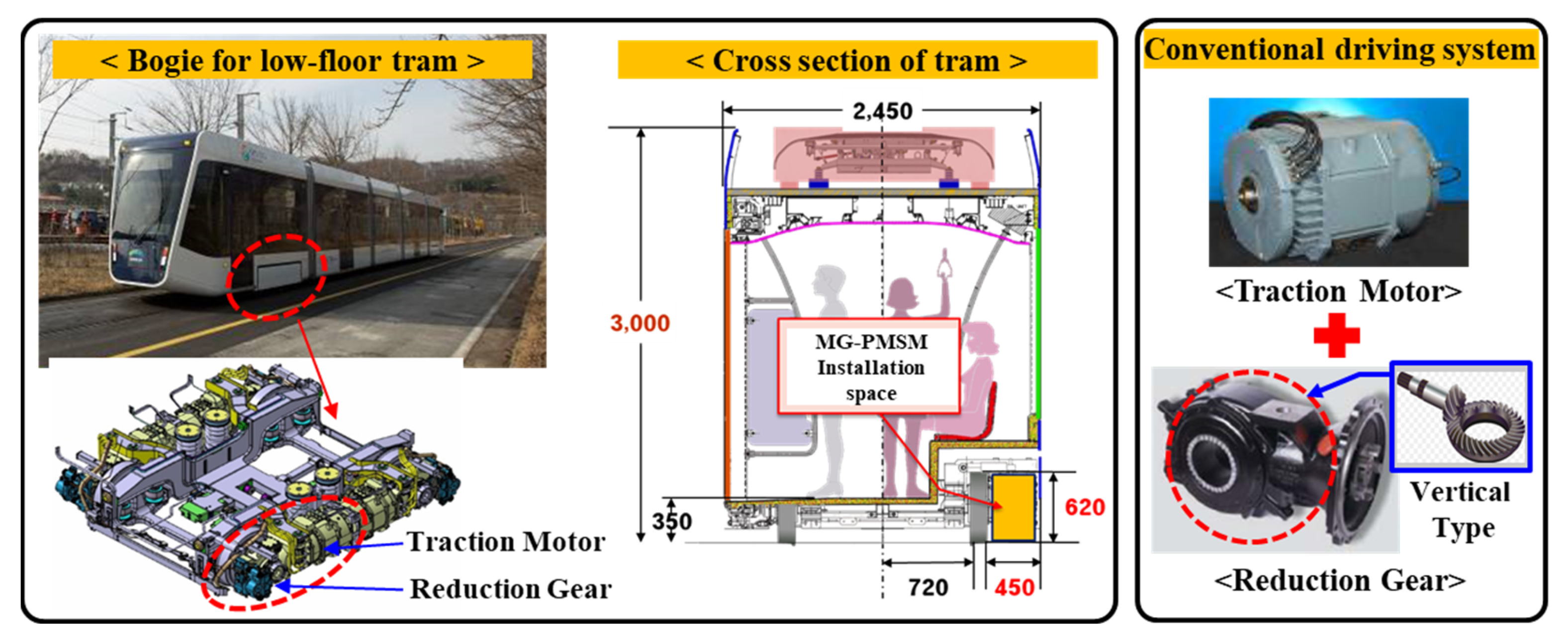
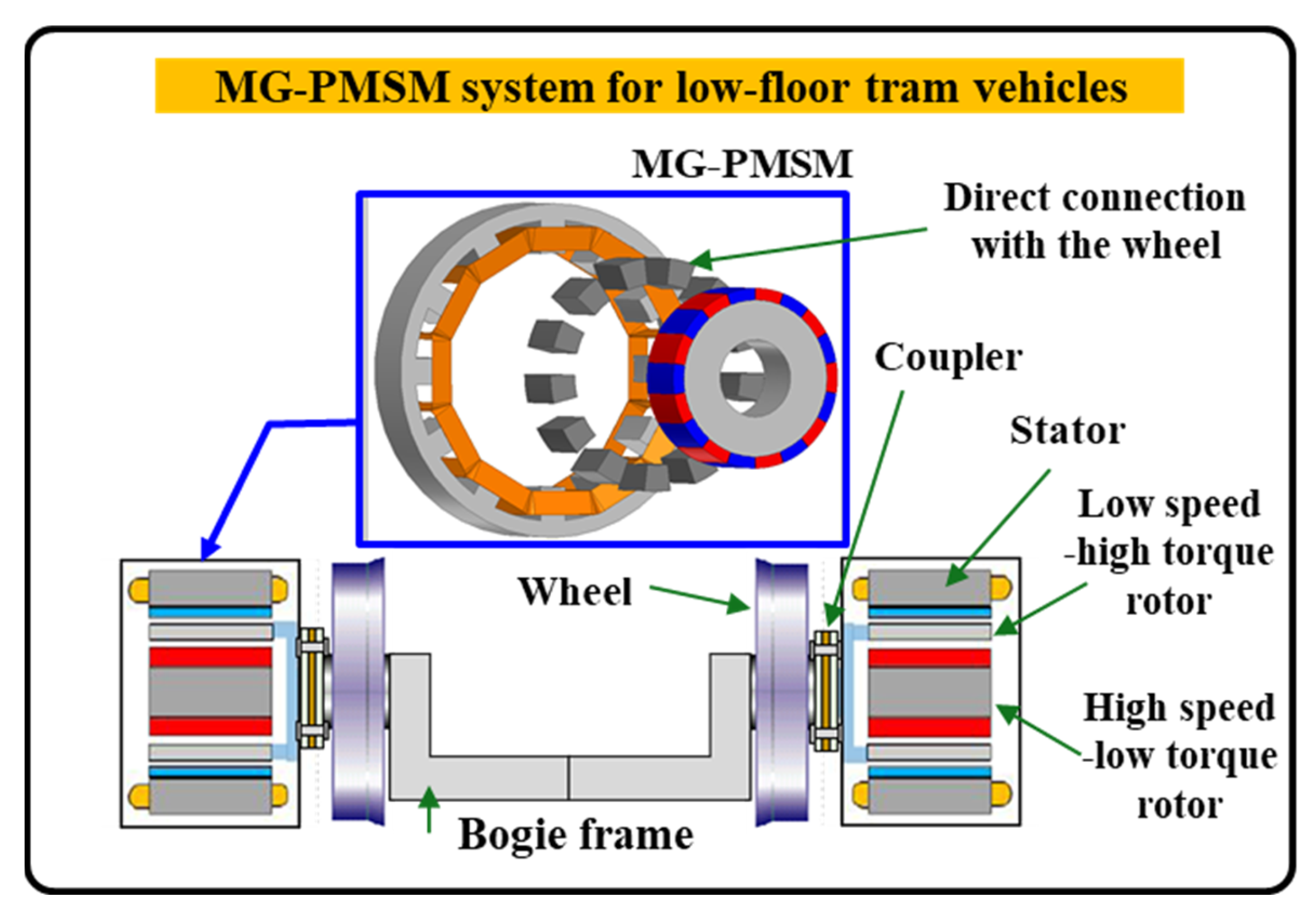
2.1. Structure of the Conventional Tram Vehicle and Design Target Specification of MG-PMSM
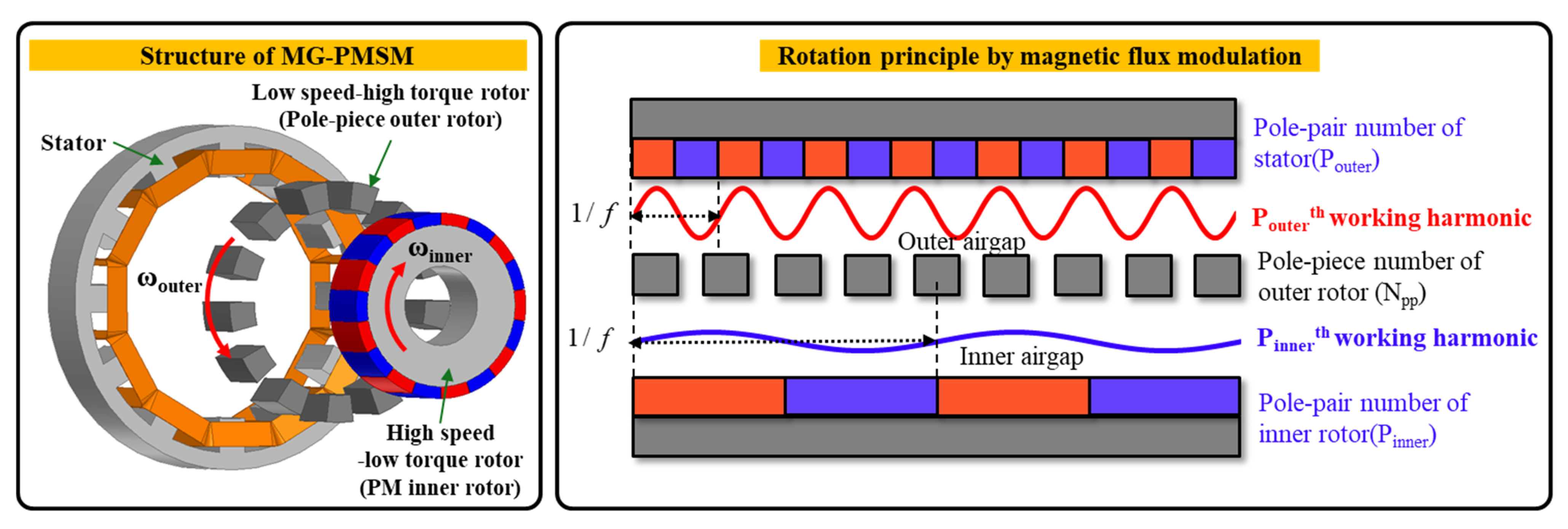
2.2. Derivation of MG-PMSM Design Model with Distributed Winding and Limits of Application for Tram Vehicle
3. Detailed Design Study for 45kW-Class MG-PMSM with Concentrated Winding
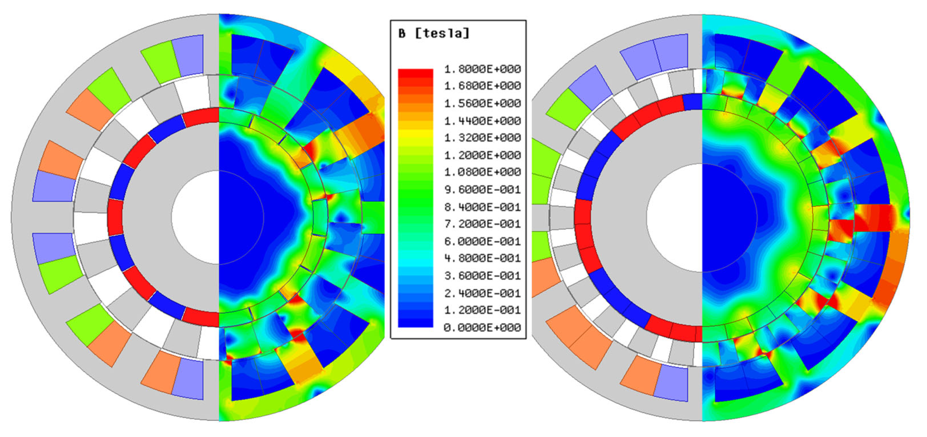
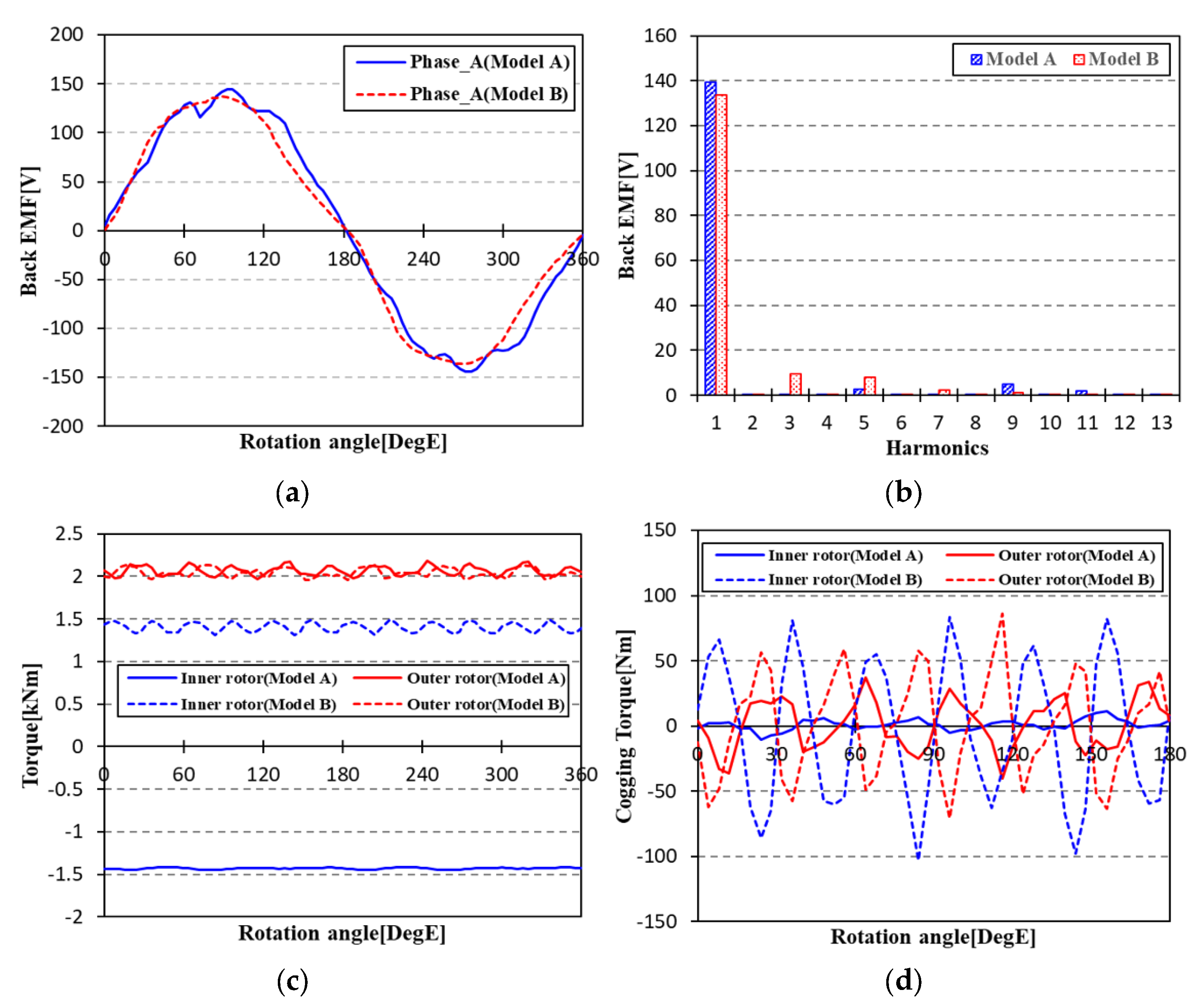
3.1. Design Topology Study for MG-PMSM with Concentrated Winding
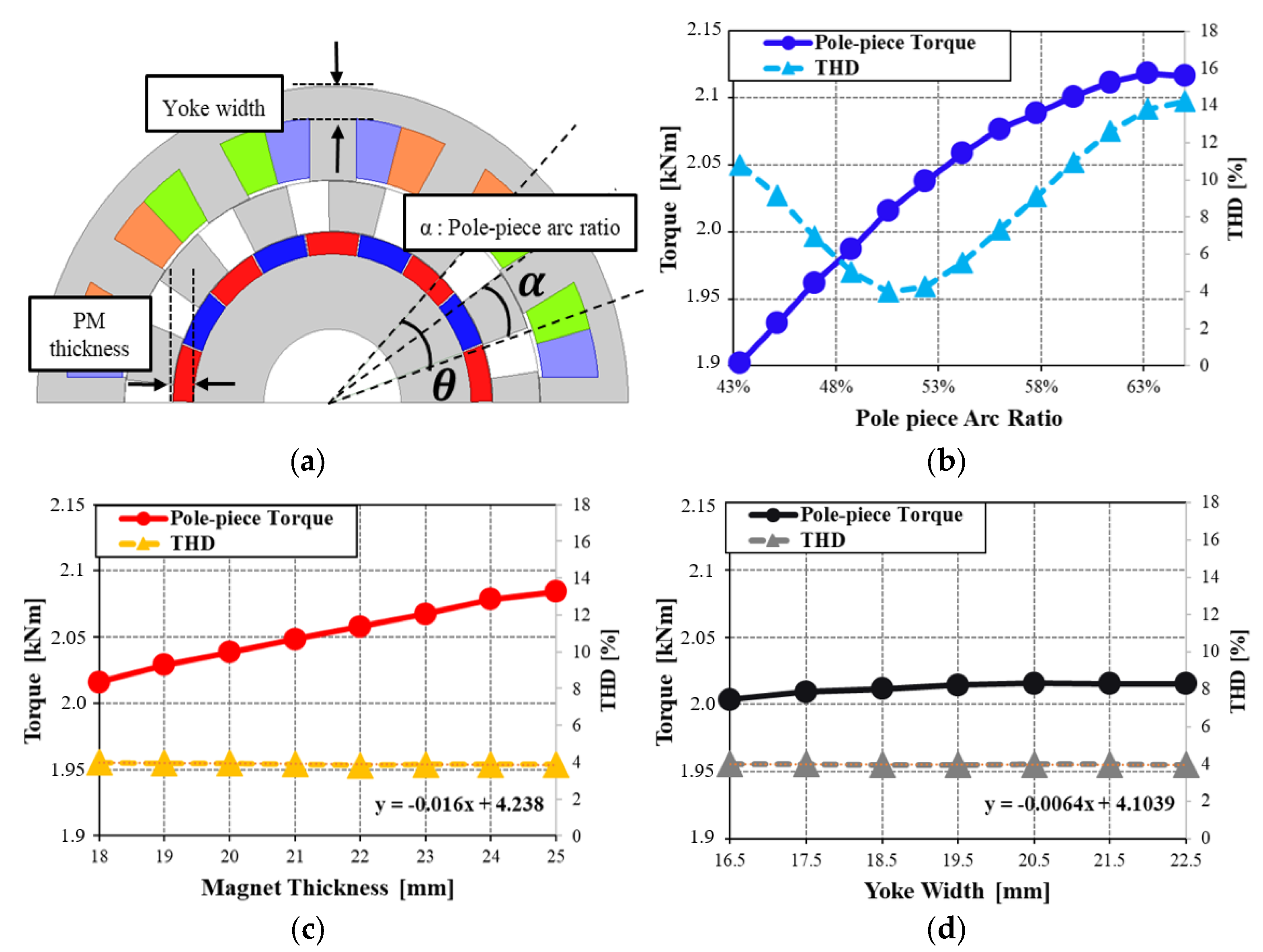
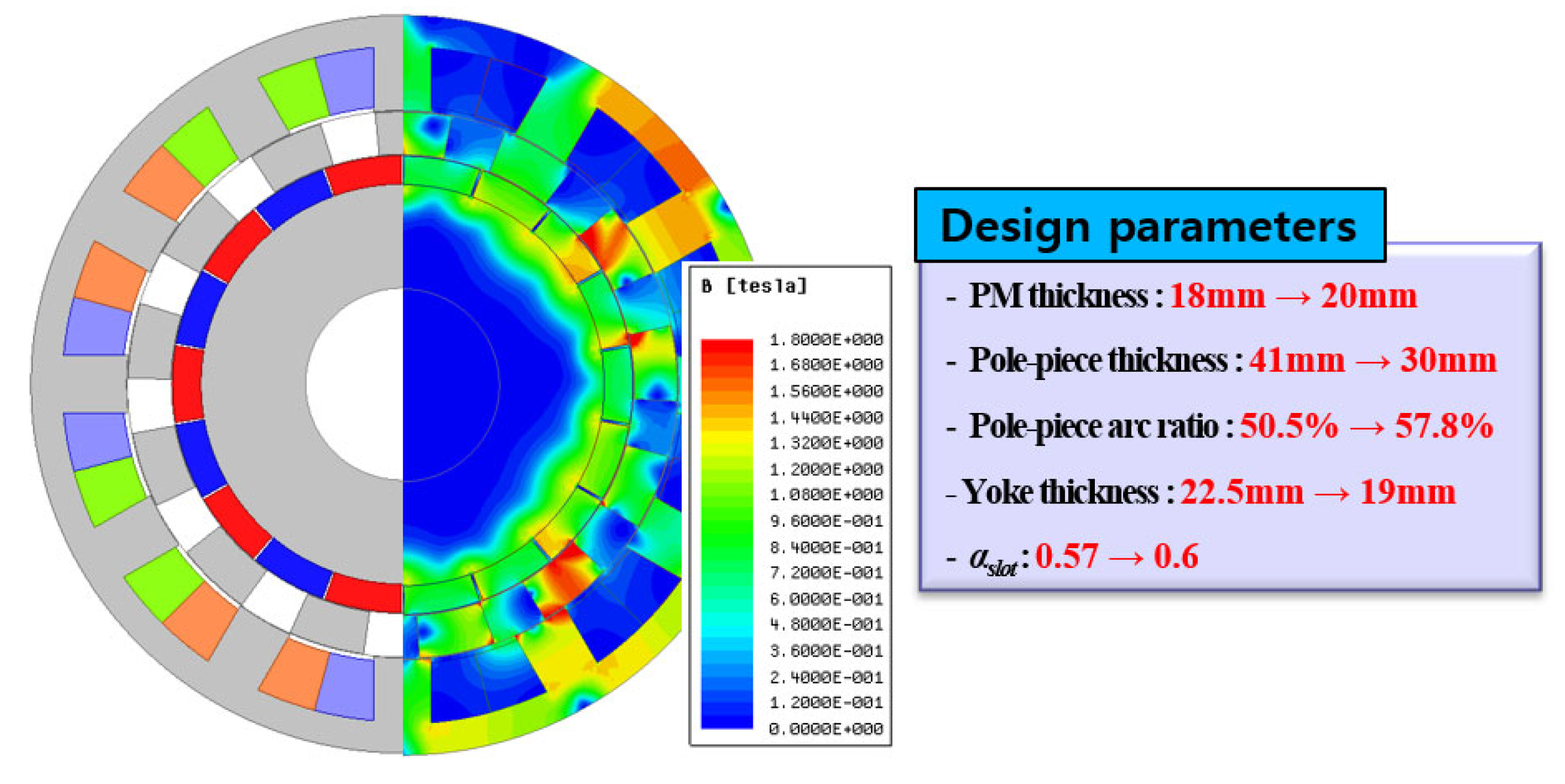
3.2. Derivation of the Detailed Design Model for 45kW-Class MG-PMSM with Concentrated Winding
4. Verification of Design Method Using a Small-Scaled MG-PMSM Prototype
4.1. Derivation of the Design Model for 4.5kW-Class Small-Scaled MG-PMSM
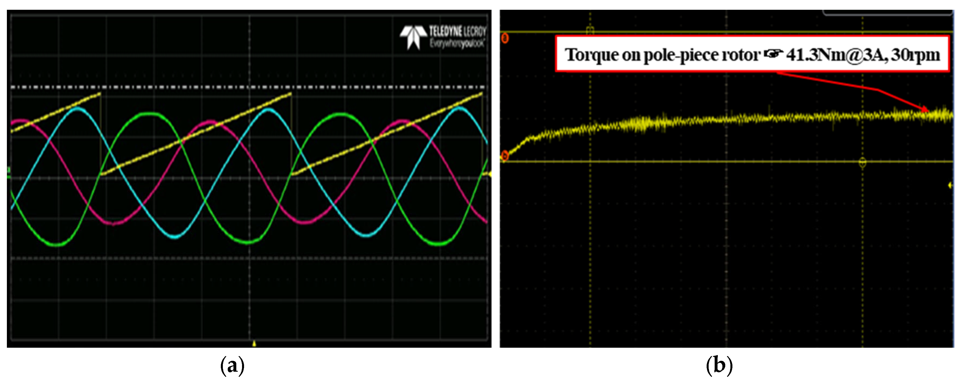
4.2. Verification of Design Method through Performance Test of the 4.5kW-Class Small-Scaled MG-PMSM Prototype
5. Conclusions
Author Contributions
Funding
Institutional Review Board Statement
Informed Consent Statement
Data Availability Statement
Conflicts of Interest
References
- Zhang, X.; Huang, Y.H. Influence of anti-kink system on curve negotiation performance of low-floor tram. Urban Rail Transit Res. 2018, 21, 111–116. [Google Scholar]
- Hondius, H. The development of low-flow trams. J. Adv. Transp. 1993, 27, 79–102. [Google Scholar] [CrossRef]
- Atallah, K.; Calverley, S.D.; Howe, D. Design, analysis and realization of a high-performance magnetic gear. IEE Proc. Electr. Power Appl. 2004, 151, 135–143. [Google Scholar] [CrossRef]
- Park, C.B.; Jeong, G. Performance verification of DR-PMSM for traction system according to permanent magnet shape. AIP Adv. 2020, 10, 025105. [Google Scholar] [CrossRef]
- McGilton, B.; Crozier, R.; McDonald, A.; Mueller, M. Review of magnetic gear technologies and their applications in marine energy. IET Renew. Power Gener. 2018, 12, 174–181. [Google Scholar] [CrossRef]
- Sun, L.; Cheng, M.; Jia, H. Analysis of a novel magnetic-geared dual-rotor motor with complementary structure. IEEE Trans. Ind. Electron. 2015, 62, 6737–6747. [Google Scholar] [CrossRef]
- Sun, L.; Cheng, M.; Zhang, J.; Song, L. Analysis and control of complementary magnetic-geared dual-rotor motor. IEEE Trans. Ind. Electron. 2016, 63, 6715–6725. [Google Scholar] [CrossRef]
- Sun, L.; Cheng, M. Key Issues in Design and Manufacture of Magnetic-Geared Dual-Rotor Motor for Hybrid Vehicles. IEEE Trans. Energy Convers. 2017, 32, 1492–1501. [Google Scholar] [CrossRef]
- Sun, L.; Cheng, M.; Wen, H.; Song, L. Motion Control and Performance Evaluation of a Magnetic-Geared Dual-Rotor Motor in Hybrid Powertrain. IEEE Trans. Ind. Electron. 2016, 64, 1863–1872. [Google Scholar] [CrossRef]
- Zhao, H.; Liu, C.; Song, Z.; Liu, S. A Consequent-Pole PM Magnetic-Geared Double-Rotor Machine with Flux-Weakening Ability for Hybrid Electric Vehicle Application. IEEE Trans. Magn. 2019, 55, 7. [Google Scholar] [CrossRef]
- Shin, K.H.; Cho, H.W.; Kim, K.H.; Hong, K.; Choi, J.Y. Analytical Investigation of the On-Load Electromagnetic Performance of Magnetic-Geared Permanent-Magnet Machines. IEEE Trans. Magn. 2018, 54, 11. [Google Scholar] [CrossRef]
- Shin, H.; Chang, J. Comparison of radial force at modulating pieces in coaxial magnetic gear and magnetic geared machine. IEEE Trans. Magn. 2018, 54, 3. [Google Scholar] [CrossRef]
- Chau, K.T.; Zhang, D.; Jiang, J.Z.; Liu, C.; Zhang, Y. Design of a Dual-rotor outer-rotor permanent-magnet brushless motor for electric vehicles. IEEE Trans. Magn. 2007, 43, 2504–2506. [Google Scholar] [CrossRef] [Green Version]
- Niguchi, N.; Hirata, K. Torque-speed characteristics analysis of a magnetic-geared motor using finite element method coupled with vector control. IEEE Trans. Magn. 2013, 49, 2401–2404. [Google Scholar] [CrossRef]
- Niguchi, N.; Hirata, K. Cogging torque characteristics of magnetic geared motor. In Proceedings of the XV International Symposium on Electromagnetic Fields in Mechatronics, Electrical and Electronic Engineering (ISEF2011), Funchal, Portugal, 1–3 September 2011. [Google Scholar]
- Morimoto, E.; Niguchi, N.; Hirata, K. Magnetic-geared motor with a continuously variable transmission gear ratio and its control method. Electron. Commun. JPN 2018, 101, 16–26. [Google Scholar] [CrossRef]
- Park, C.B.; Jung, D.H.; Jeong, G. Wireless tram propulsion system specification analysis and magnetic gear design strategy. J. Korean Soc. Railw. 2020, 23, 784–793. [Google Scholar] [CrossRef]
- Korea Railroad Research Institute. Development of system technology for wireless low-floor tram. In Land, Infrastructure and Transportation R&D Report; KRRI: Uiwan-si, Korea, 2013. [Google Scholar]
- Park, C.B.; Jeong, G. Design and Analysis of Dual-rotor Permanent Magnet Synchronous Motor for Driving Electric Vehicles. In Proceedings of the ICEMS 2017 Conferences, Sydney, Australia, 11–14 August 2017. [Google Scholar]
- Lee, J.J.; Kim, W.H.; Yu, J.S.; Yun, S.Y.; Kim, S.M.; Lee, J.J.; Lee, J. Comparison between concentrated and distributed winding in IPMSM for traction application. In Proceedings of the 2010 International Conference on Electrical Machines and Systems, Incheon, Korea, 10–13 October 2010. [Google Scholar]
- Munoz, A.R.; Liang, F.; Degner, M.W. Evaluation of Interior PM and Surface PM Synchronous Machines with Distributed and Concentrated Winding, Industrial Eletronics, 2008. In Proceedings of the IECON 2008—34th Annual Conference of IEEE, Orlando, FL, USA, 10–13 November 2008; pp. 1189–1193. [Google Scholar]


| Contents | Design Criteria |
|---|---|
| MG-PMSM installation space | Max. Dia. 620 mm/Depth 450 mm |
| Required size of MG-PMSM | Max. Dia. 520 mm/Depth 400 mm (Based on the stator out dia.) |
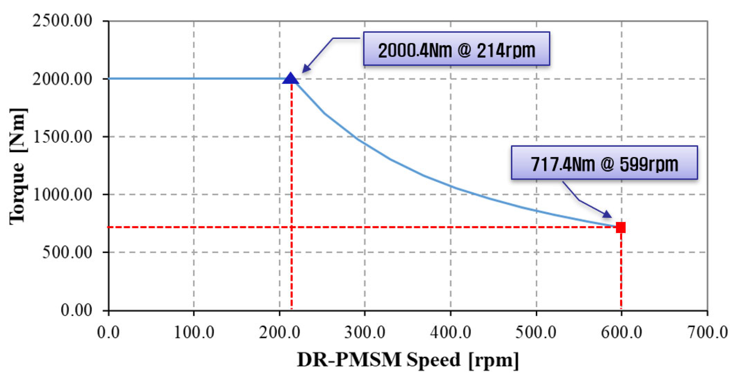
| Required torque | 2 kNm@214 rpm/0.71 Nm@599 rpm |
| Efficiency | 92% |
| Contents | Model 1 (30 Slots) | Model 2 (30 Slots) | Model 3 (42 Slots) | Model 4 (42 Slots) |
|---|---|---|---|---|
| Stator poles | 10 | 4 | 14 | 4 |
| Pole pieces | 7 | 7 | 9 | 9 |
| Rotor poles | 4 | 10 | 4 | 14 |
| Rated torque (kNm) | 2.04 | 2.16 | 1.89 | 2.05 |
| Torque ripple (%) | 13.8 | 3.8 | 17.5 | 7.4 |
| Efficiency (%) | 76.4 | 75.9 | 85.3 | 92.5 |
| Contents | Value |
|---|---|
| Stator slots/Stator poles/Pole pieces/Rotor poles | 42/4/9/14 |
| Gear ratio 1 (Pole pieces/Stator pole pairs) | 4.5 |
| Gear ratio 2 (Rotor pole pairs/Stator pole pairs) | 3.5 |
| Gear ratio 3 (Pole pieces/Rotor pole pairs) | 0.643 |
| Outer Dia. Of stator/Stack length/Axial length with end turns | 508/267/480 mm |
| DC link voltage/IPhase @ Rated speed | 750 Vdc /115 Arms |
| Tave._rated/Torque ripple @ Rated speed | 2096.5 Nm/8.8% |
| Tave._max./Torque ripple @ Max. speed | 758.1 Nm/15% |
| THD (No-load/Full-load) @ Rated speed | 4.1/6.1% |
| RPhase @ 20 °C/Back-EMFPhase-fund.@ Max. speed | 0.094 Ω/249.6 V |
| Copper loss/Iron loss/Eddy current loss in PM/Efficiency @ Rated speed | 1,243.3/133.2/64 W/94.6% |
| Core/Magnet material grade | 30PNF1600/NdFeB(38UH) |
| Contents | Model (Topology) A | Model (Topology) B |
|---|---|---|
| Method of deriving the no. of pole piece | ||
| Gear ratio | ||
| Speed-torque |
| Contents | Value | |
|---|---|---|
| Model (Topology) A | Model (Topology) B | |
| Stator slots/Stator poles/Pole pieces/Rotor poles | 12/8/13/18 | 12/10/22/10 |
| Gear ratio 1 (Pole pieces/Stator pole pairs) | 3.25 | 4.4 |
| Gear ratio 2 (Rotor pole pairs/Stator pole pairs) | 2.25 | 1 |
| Gear ratio 3 (Pole pieces/Rotor pole pairs) | 0.722 | 4.4 |
| Outer Dia. Of stator/Stack length/Axial length with end turns | 520/180/210 mm (Volume 45% ▼) | 520/265/305 mm |
| IPhase @ Rated speed | 258 Arms | 581 Arms |
| Tave._rated/Torque ripple @ Rated speed | 2068 Nm/10.7% | 2045 Nm/9.1% |
| THD of Back-EMF (No-load/Full-load) @ Rated speed | 4.5/4.7% | 12.0/9.3% |
| Back-EMFPhase-fund. @ Max. speed | 390 V | 374 V |
| Copper loss/Iron loss/Eddy current loss in PM @ Rated speed | 1325/101/415 W | 1034/177/1359 W |
| Efficiency @ Rated speed | 96.7% (2.98% ▲) | 93.9% |
| Contents | Value |
|---|---|
| Outer Dia. Of stator/Stack length/Axial length with end turns | 520/160/190 mm |
| DC link voltage/IPhase @ Rated speed | 750 Vdc/199 Arms |
| Tave._rated/Torque ripple @ Rated speed | 2083 Nm/6.8% |
| THD of Back-EMF (No-load/Full-load) @ Rated speed | 4.0/4.2% |
| Back-EMFPhase-fund.@ Max. speed | 385 V |
| Copper loss/Iron loss/Eddy current loss in PM @ Rated speed | 883/85/524 W |
| Efficiency @ Rated speed | 96.9% |
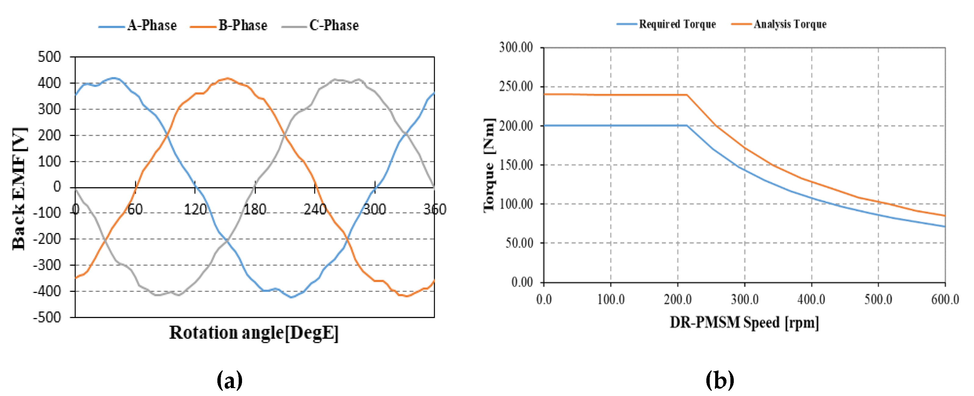
| Design Model and Magnetic Flux Density Distribution | Contents | Value |
|---|---|---|
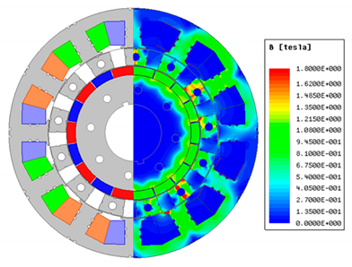 | Outer Dia. of stator | 260 mm |
| Stack length of stator | 210 mm | |
| Gear ratio 1/2 | 4.5/3.5 | |
| IPhase @ Rated speed | 16 Arms | |
| Tave._rated @ Rated/Max. speed | 236.2/78.6 Nm | |
| Tripple @ Rated/Max. speed | 5.4/21.5% | |
| Phase resistance @ 20 °C | 0.77 Ω | |
| Back-EMFPhase-fund.@ Max. speed | 422.1 V @ Full-load | |
| Efficiency @ Rated speed | 96.1% |
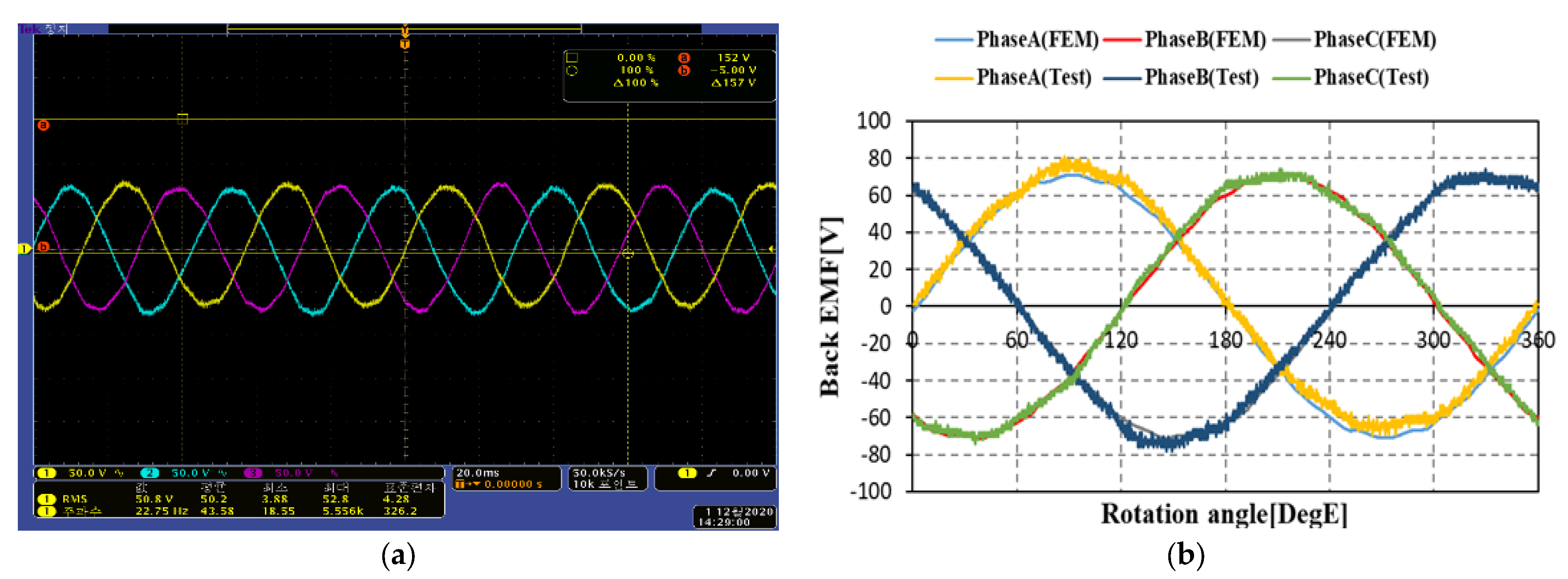
| Contents | Calculation | Measurement | Difference Rate |
|---|---|---|---|
| Back-EMFPhase-rms | 50.0 V | 50.2 V | 0.4% |
| Back-EMFPhase-fund.-peak | 72.3 V | 68.6 V | 5.1% |
| Frequency | 23.18 Hz | 22.75 Hz | 1.9% |
Publisher’s Note: MDPI stays neutral with regard to jurisdictional claims in published maps and institutional affiliations. |
© 2021 by the authors. Licensee MDPI, Basel, Switzerland. This article is an open access article distributed under the terms and conditions of the Creative Commons Attribution (CC BY) license (https://creativecommons.org/licenses/by/4.0/).
Share and Cite
Lim, J.-H.; Jeong, G.; Lee, H.-W.; Lee, J.-B.; Lim, J.-S.; Park, C.-B. Design and Analysis of the 45kW-Class Magnetic Geared Permanent Magnet Synchronous Motor for Traction of Tram Vehicles. Appl. Sci. 2021, 11, 6360. https://doi.org/10.3390/app11146360
Lim J-H, Jeong G, Lee H-W, Lee J-B, Lim J-S, Park C-B. Design and Analysis of the 45kW-Class Magnetic Geared Permanent Magnet Synchronous Motor for Traction of Tram Vehicles. Applied Sciences. 2021; 11(14):6360. https://doi.org/10.3390/app11146360
Chicago/Turabian StyleLim, Jae-Hyeon, Geochul Jeong, Hyung-Woo Lee, Jae-Bum Lee, Jong-Seok Lim, and Chan-Bae Park. 2021. "Design and Analysis of the 45kW-Class Magnetic Geared Permanent Magnet Synchronous Motor for Traction of Tram Vehicles" Applied Sciences 11, no. 14: 6360. https://doi.org/10.3390/app11146360
APA StyleLim, J.-H., Jeong, G., Lee, H.-W., Lee, J.-B., Lim, J.-S., & Park, C.-B. (2021). Design and Analysis of the 45kW-Class Magnetic Geared Permanent Magnet Synchronous Motor for Traction of Tram Vehicles. Applied Sciences, 11(14), 6360. https://doi.org/10.3390/app11146360