Article

Experimental Study on the Pullout Resistance of Smooth Steel Strip Reinforcement with Transverse Members

1
School of Civil and Environmental Engineering, Urban Design and Studies, Chung-Ang University, Seoul 06974, Korea
2
Department of Intelligent Energy and Industry, Chung-Ang University, Seoul 06974, Korea
3
Department of Infrastructure Safety Research, Korea Institute of Civil Engineering and Building Technology, Goyang-si 10223, Korea
4
Department of Civil and Disaster Prevention Engineering, Halla University, Wonju-si 26404, Korea
5
Incheon Disaster Prevention Research Center, Incheon National University, Incheon 22012, Korea
*
Authors to whom correspondence should be addressed.
Appl. Sci. 2021, 11(6), 2776; https://doi.org/10.3390/app11062776
Submission received: 23 February 2021 / Revised: 15 March 2021 / Accepted: 16 March 2021 / Published: 19 March 2021
(This article belongs to the Special Issue Advances in Geotechnical Engineering Ⅱ)

Abstract

:
This paper presents an experimental study on the pullout resistance of a newly improved reinforcement. The applied reinforcement was a smooth steel strip reinforcement with transverse members used to improve the pullout-resistance problems of the smooth steel strip reinforcement. The pullout and bearing resistance of the improved reinforcement were evaluated using results of large-scale pullout tests. The evaluation result confirmed that the bearing resistance of the improved reinforcement was about 33–66% of the total pullout resistance, and it had an evenly distributed friction and bearing resistance. The bearing bond coefficient, considering the interference effect, gradually converged when normal stress was higher than a certain value. This result confirmed that the increment of interference effect is caused by the increment of the transverse member and normal stress. In the pullout-resistance evaluation of the improved reinforcement, a number of transverse members can be predicted using the relationship between bearing-resistance stress and the bearing bond coefficient due to normal stress, which can be applied as a reasonable prediction method.

1. Introduction

Reinforcements are used to improve the stability of abutments, embankments, slopes, and walls [1,2,3,4,5,6,7]. Various reinforcements have been developed and applied since the introduction of the reinforced earth wall consisting of inextensible and extensible reinforcements according to material characteristics. Inextensible reinforcement includes smooth steel strip and ribbed steel strip types and welded steel grids. Extensible reinforcements include geogrid, geotextile, and geosynthetic strip types. In these reinforcements, pullout resistance is very important as an evaluation factor for the stability of the reinforced earth wall. Generally, the pullout resistance of reinforcements can be classified into two resistance characteristics; that is, total pullout resistance can be explained as the summation of friction resistance due to longitudinal members and bearing resistance due to transverse members [8]. Friction-resistance reinforcements include smooth steel strips and geotextile and geosynthetic strips. Reinforcements in which friction resistance is synchronized with bearing resistance are the ribbed steel strip, welded steel grid, and geogrid types. In friction-resistance reinforcements, various problems occur due to the type of backfill material used because total pullout resistance takes effect only due to friction resistance. However, grid-type reinforcements, including two types of resistance, namely, the combination of friction and bearing resistance, are more structurally stable than friction-resistance reinforcements are. Most pullout resistance in inextensible mesh-type reinforcements is caused by bearing resistance, and the rigidity of transverse members has a significant effect on bearing resistance [9,10]. That is, the deformation of transverse members can adversely affect the stability of reinforced earth walls. Therefore, if steel strip reinforcement friction resistance that has a primary pullout resistance can be added to the transverse members in the resistant zone, the problem of the existing steel grid is improved. This reinforcement can be the improved type considering the anchor retaining effect because the number of transverse members can be selectively applied in resistant zones.
In the early stages of the introduction of the reinforced earth wall in Korea, smooth steel strip reinforcement was mostly used, and ribbed steel strip reinforcement was then applied to increase friction resistance between reinforcement and backfill material. However, the reduction in durability due to the corrosion of the steel reinforcement led to a rapid decrease in its application. The use of the geogrid-reinforced earth wall has greatly increased since the late 1990s [11], and about 6.5 million m2 of geogrid was applied to reinforced earth walls in 2005 [12]. A large effective site is required due to Korea’s mountainous topographical feature. Therefore, the number of cases of the application of reinforced earth walls that have a wall height of 10–15 m is increasing to support heavier surcharge load. For this reason, reinforced earth walls need reinforcement to improve soil strength. The application of backfill materials has material criteria to increase the pullout resistance of the geogrid and prevent damage due to compaction. The maximal particle size of backfill soil should be less than 19 mm [12]. However, weathered granite soil, which is more than 19 mm, is sometimes applied to backfill material because it is difficult to obtain fine soil due to the field conditions. Furthermore, strength-reduction factors considering the extensibility of the geogrid that is excessively applied in a reinforced earth wall needs to be in sufficient control for wall displacement. Therefore, it is necessary to study inextensible reinforcements since most corrosion problems are solved by developing and applying an anticorrosion technique. In addition, the application of inextensible reinforcement that has considerable pullout resistance has increased.
In this study, inextensible reinforcement is improved, which resolves the problem of the existing smooth strip reinforcement. The form of the improved reinforcement is smooth steel strip reinforcement with transverse members. In other words, transverse members are combined with a punched smooth steel strip to increase total pullout resistance due to bearing resistance. Transverse members can be installed on the punched smooth steel strip reinforcement according to the required pullout resistance in the resistant zone of the reinforced soil mass. Bearing resistance is, therefore, due to transverse members being similar to the anchor retaining effect. Pullout tests of the improved reinforcement should be conducted to analyze the pullout mechanism.
Therefore, large-scale pullout tests for improved types of reinforcements were conducted to analyze the pullout characteristics of the improved reinforcement. First, its pullout behavior was evaluated by the analytical results of the pullout tests, and bearing resistance was evaluated to analyze the effect of transverse members in total pullout resistance. Second, the bearing bond coefficient was evaluated considering the interference effect of transverse members, and the predicted method of transverse members is suggested by design case.

2. Theoretical Background on Pullout Resistance

2.1. Pullout Resistance of Reinforcement

The internal stability of a reinforced earth wall should be evaluated on the basis of the stability of tensile failure and pullout failure. Inextensible reinforcement has significantly higher stability of tensile failure because its tensile strength is greater than that of extensible reinforcement. However, the stability of pullout failure differs from the evaluation factor of pullout resistance according to whether a transverse member is installed. Therefore, the mechanisms of the longitudinal and transverse members depend on resistance type. If transverse members do not exist, only friction resistance is considered; otherwise, friction resistance due to the longitudinal member and the bearing resistance due to the transverse member should be considered [9,13]. Therefore, the pullout resistance of reinforcement should be evaluated from pullout test results. Over the last few years, many experimental tests and theoretical studies were carried out to follow up on the pullout mechanism of reinforcement [10,14,15,16,17,18,19,20,21,22,23]. Jewell et al. [8] and Peterson and Anderson [21] proposed theoretical equations on friction resistance and bearing resistance. Bergado et al. [9,14,24] and Matsui et al. [25,26] evaluated the pullout behavior and bearing resistance of transverse members on a steel grid. The total pullout resistance of reinforcement ( P p ) can be expressed as follows [13]:
P p = 2   L r   W r   σ v   f b   t a n ,
where f b is the bond coefficient; σ v is the effective normal stress in the soil to the reinforcement surface; L r and W r are the length and width of the reinforcement providing bond (i.e., being pulled out), respectively; and is the internal friction angle of the soil.
Total pullout resistance can be divided into friction P p ( f r ) and bearing resistance P p ( b r ) , and these are expressed in Equations (2) and (3), respectively [13].
P p ( f r ) = 2   α s   L r W r   σ v   t a n δ ,
where α s is the fraction of the reinforcement plan area; A r =   L r W r , which is solid (i.e., the plane reinforcement surface area); and δ is the friction angle between soil and reinforcement.
P p ( b r ) = ( L r S )   W r   α b   B   σ b ,
where α b is the fraction of each bearing surface area W r   B , available for bearing (loss of area due to connections), B is the thickness of transverse members, L r / S is the number of bearing surfaces, and σ b is the bearing resistance stress of the transverse member. From Equations (1)–(3), the general expression for the bond coefficient is [13].
f b = α s   ( t a n δ t a n ) +   ( α b   B S )   ( σ b σ v )   1 2   tan .
Generally, the inter-relation between the pullout resistance strength and maximal pullout force of reinforcement can be calculated in order to evaluate the pullout parameters as follows:
P r = 2   τ p   W r L r ,
where P r is maximal pullout force and τ p is pullout strength.
The pullout-resistance mechanism of the improved reinforcement can be explained as follows. First, the connection pin (transverse member), of which the number of transverse members ranges from 1 to 3, is inserted into the punched smooth steel strip. Second, longitudinal members have friction resistance with the existing smooth steel strip reinforcement. Bearing resistance between soil and reinforcement is also increased because the inserted transverse members have an anchor effect in the soil. Therefore, pullout-resistance characteristics should be analyzed for two resistance types.

2.2. Bearing Resistance of Transverse Members

The bearing resistance of transverse members is related to the cohesion, friction angle, and bearing-capacity factors in the Terzaghi–Buisman bearing-capacity equation, which was modified into the following form [21]:
σ b   =   c · N c   +   σ v · N q ,
where c is soil cohesion, σ v is the effective normal stress of the soil to the reinforcement surface, σ v and N q are bearing capacity factors, and N q is the failure mechanism factor. The bearing resistance stress ( σ b ) of transverse members can be expressed as follows [24]:
P p ( b r ) = n · w · d · σ b ,
where n is the number of transverse members, w is the width of the transverse members, and d is the diameter of transverse members. The bearing resistance of transverse members is expressed by the assumed failure mechanism, such as general shear failure [24] and punching shear failure [8]. The value for N q can be calculated according to the failure mechanism as shown in Equations (8) and (9). The value for N c of the two failure mechanisms is taken as shown in Equation (10).
N q   =   e ( π   tan ) tan 2 ( 45 ° +   2 )
N q   =   e ( π 2   +   )   tan tan ( 45 ° +   2 )
N c   =   ( N q   1 )   cot

2.3. Interference Effect

Interference between transverse members has a considerable effect on the bond coefficient, as was confirmed by [19]. Determining the distance between transverse members is particularly important because if the distance between transverse members increases to reduce the interference effect, total pullout resistance is decreased due to reduced bearing resistance. Therefore, the interference effect between transverse members was proposed to evaluate the degree of interference, as follows [19]:
D I   =   1     ( P p n P o ) ,
where DI is the degree of interference, P p is the maximal pullout force for the reinforcement with   n transverse members, and P o is the maximal pullout force for an isolated transverse member of the same reinforcement. The bearing bond coefficient can be calculated considering the bond coefficient proposed by [8], as follows [19]:
f b ( b e a r i n g ) = ( 1 D I )   ( α b   B S )   ( σ b σ v )   1 2   tan

3. Experiment Overview

Large-scale pullout tests were carried out to evaluate pullout resistance in the reinforcement by a combination of smooth steel strips and transverse members.

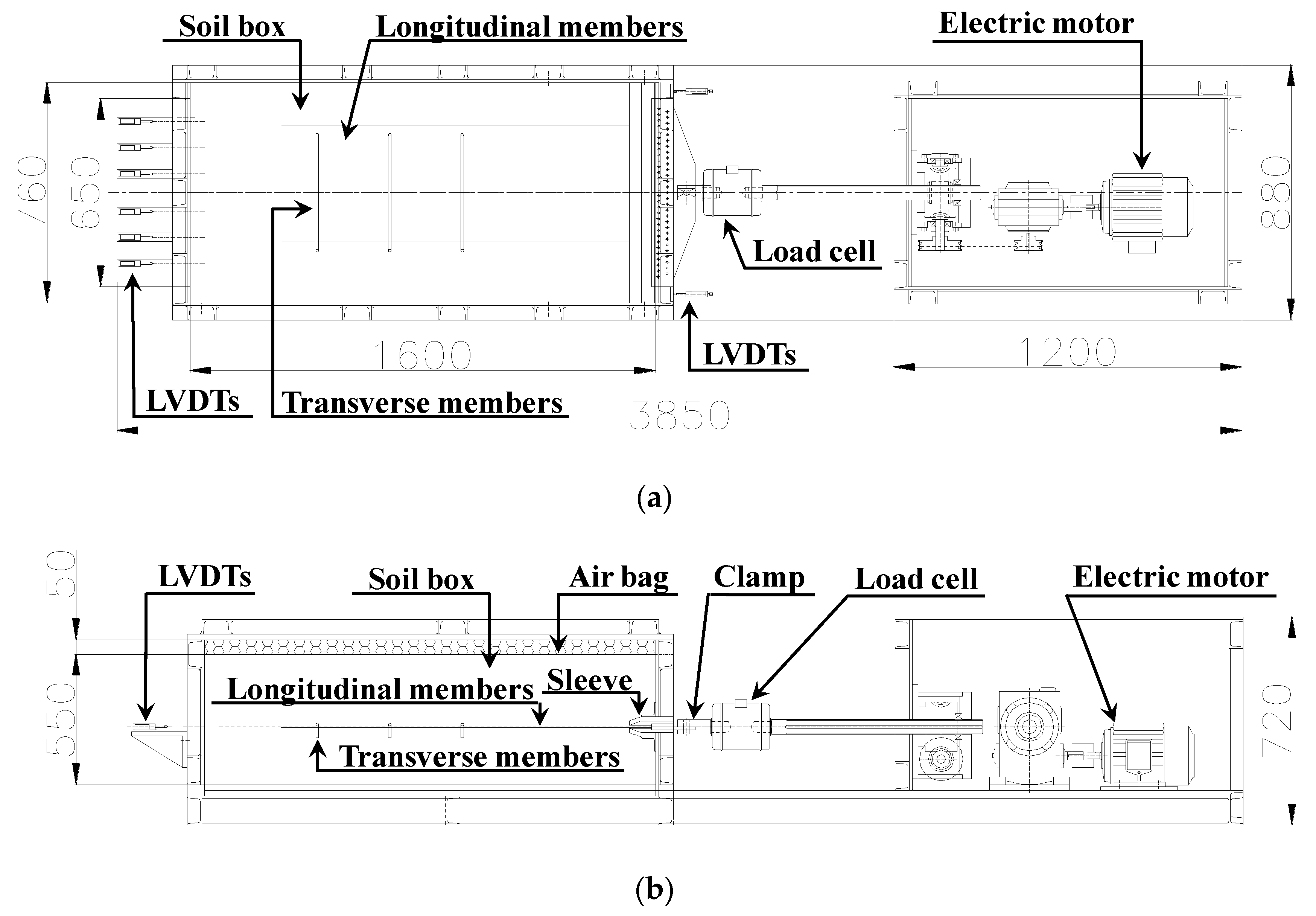
3.1. Large-Scale Pullout Testing Apparatus

The large-scale pullout testing apparatus used in this study was manufactured by Iljin ENG (Incheon, South Korea), and it consisted of a rigid (soil) box, load (normal and pullout) device, and control box, as shown in Figure 1. The dimensions of the used rigid box (1600 mm length, 760 mm width, and 550 mm height) exceeded the recommended minimal dimensions given by ASTM (American Society for Testing and Materials) [27]. The rigid box can endure a pressure of 700 kPa. Normal stress could be applied up to 500 kPa by using an air bag, which provided a uniform surcharge load that was considered for the field condition. The pullout load was adopted for displacement control method using an electric motor that has control capacity for the displacement rate of 0.5–30 mm/min, and maximal pullout force was controlled up to 200 kN.

3.2. Material Characteristics

3.2.1. Soil Properties

Large-scale pullout tests were conducted using nonplastic soil that was classified as SW according to the Unified Soil Classification System (USCS) and had a percentage passing of 4.07%. The optimal water content and maximal dry unit weight obtained from compaction tests were 14.1% and 18.82 kN/m2, respectively. Direct shear tests were conducted to determine shear strength, and the cohesion and internal friction angle of the soil were 8.7 kPa and 35.6°, respectively, which corresponds to typical weathered granite soil [28,29]. Soil characteristics are shown in Table 1.

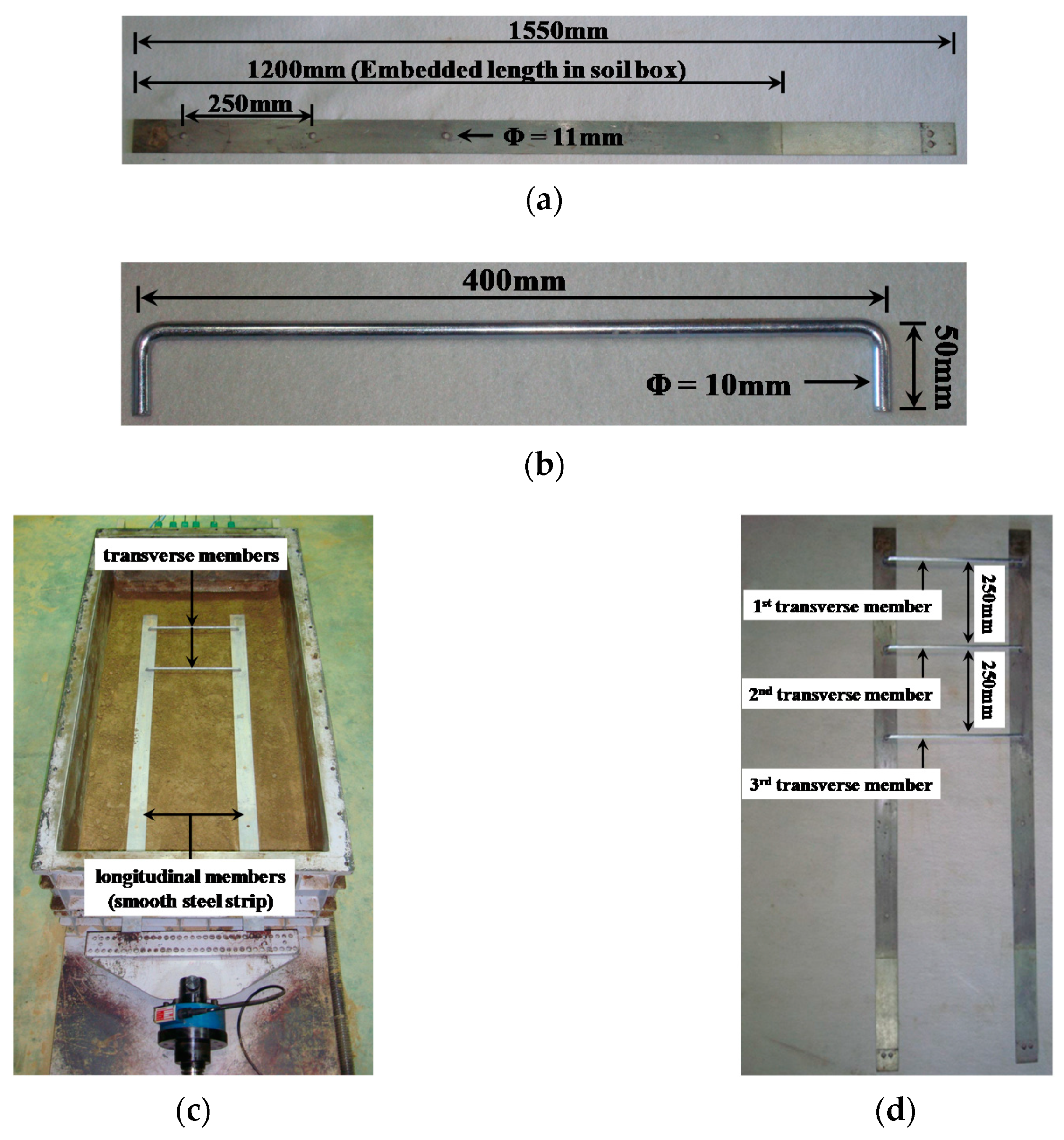
3.2.2. Reinforcement

Large-scale pullout tests were performed on the two types of inextensible reinforcement. One was the existing smooth steel strip (Type A), and the other was the newly improved reinforcement (Type B), produced by pinning together a combination of punched smooth steel strips and transverse members, as shown in Figure 2. The size of Type A and B reinforcements for longitudinal members was 1200 mm effective length for insertion into the test box, 65 mm width, and 5 mm thickness. The dimensions of the transverse member were of 10 mm diameter, 400 mm length, and 50 mm height with an ∩ shape. The longitudinal members of Type B had 11 mm of punching diameter to allow for easy insertion into the transverse members; the installed reinforcement in the soil box is shown in Figure 2c. The first transverse member was installed at 100 mm from the end of the longitudinal member. The other transverse members were located for an anchor effect at intervals of 250 mm as shown in Figure 2d.

3.3. Testing Program and Procedure

As mentioned above, the pullout tests were carried out according to the recommended method in ASTM [27] to evaluate the resistance effect of transverse members using Types A and B. The testing program and test classifications are listed in Table 2. The numbers of transverse members were applied in the cases of none and 1 to 3 members, which confirmed the effect on pullout resistance due to transverse members and normal stress. Tests were conducted four times to confirm the bearing-resistance effect due to the installation location of the transverse member. Soil conditions were similar in all tests.
The soil, which had a lower and upper ground in the test box, comprised three layers compacted using a rammer (impact force, 14 kN; impacts per min, 640–680) onto each ground. The compaction ratio of each layer was applied to exceed 95%. Transverse members were inserted to maximize bearing resistance in the soil. Normal stresses varied from 25 to 200 kPa considering compacted soil and backfill height. Friction between the soil and box was reduced using an oiled wrap, and a displacement rate of 1 mm/1 min was equally applied. Front displacement using linear variable differential transformers (LVDTs) was measured as follows: (1) in the case of nontransverse members (Type A), the pullout force was measured until convergence, and (2) in the case of the existing transverse members (Type B), the front displacement was measured up to 160 mm.

4. Test Results and Discussion
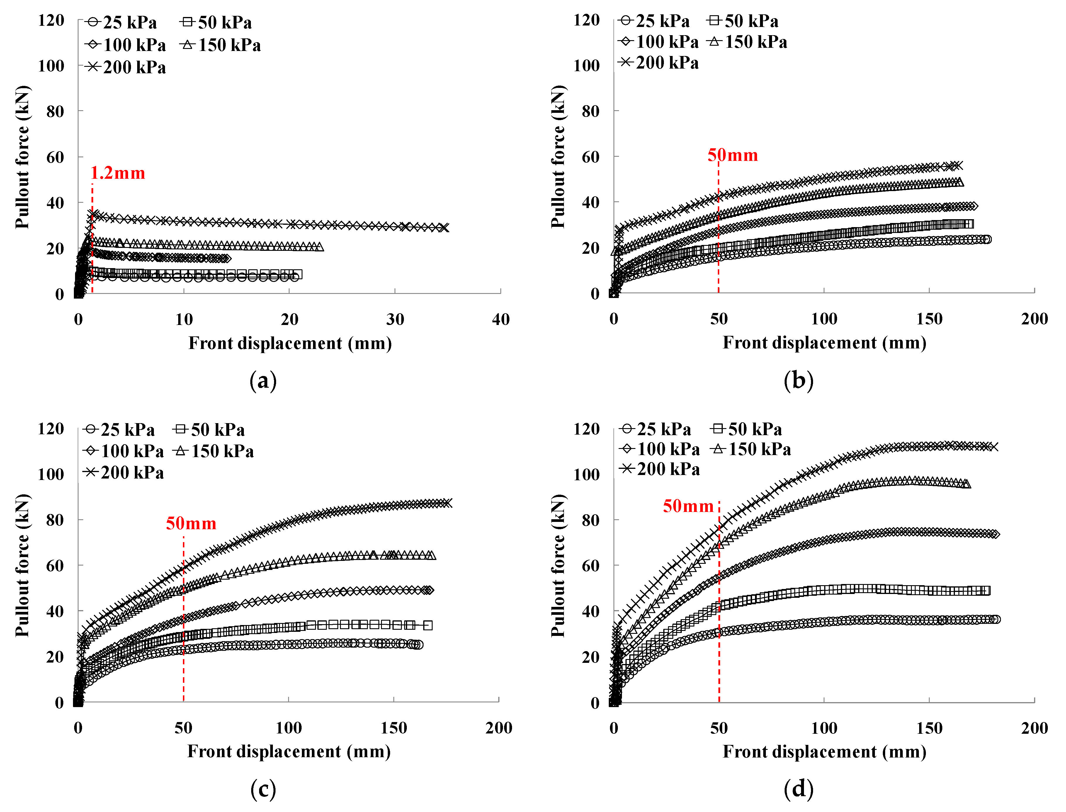
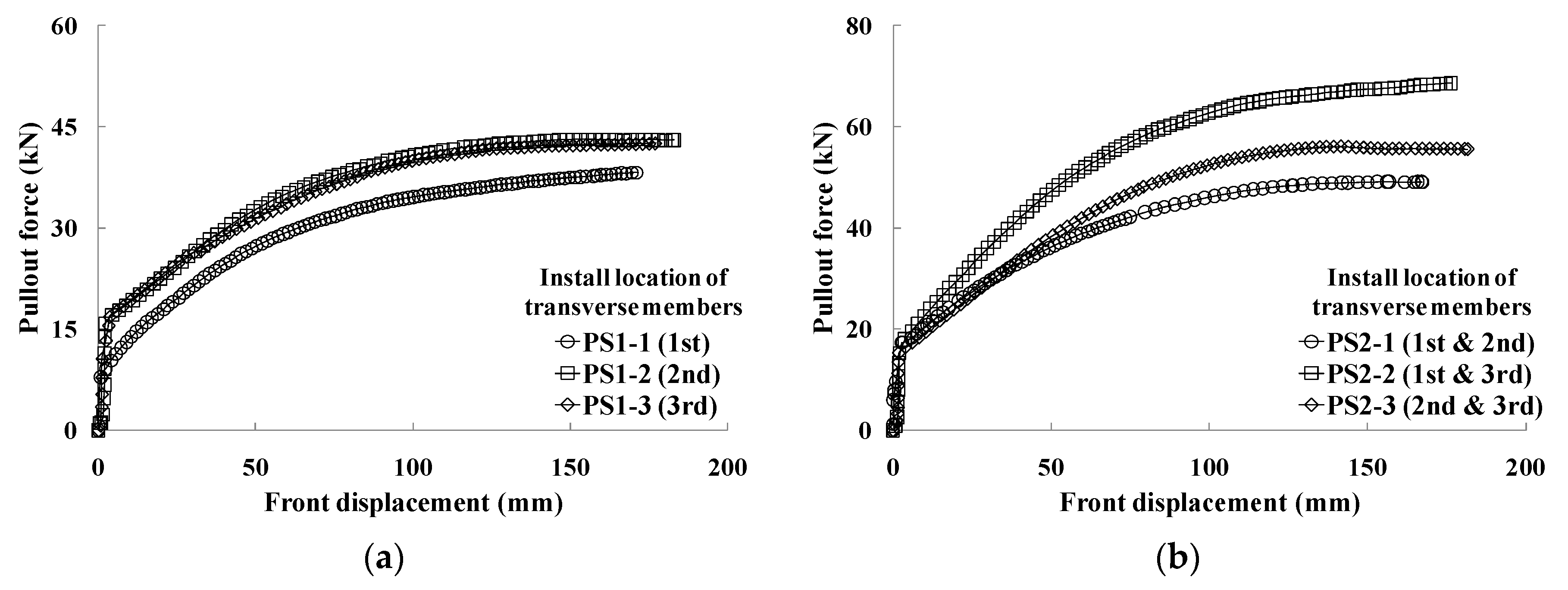
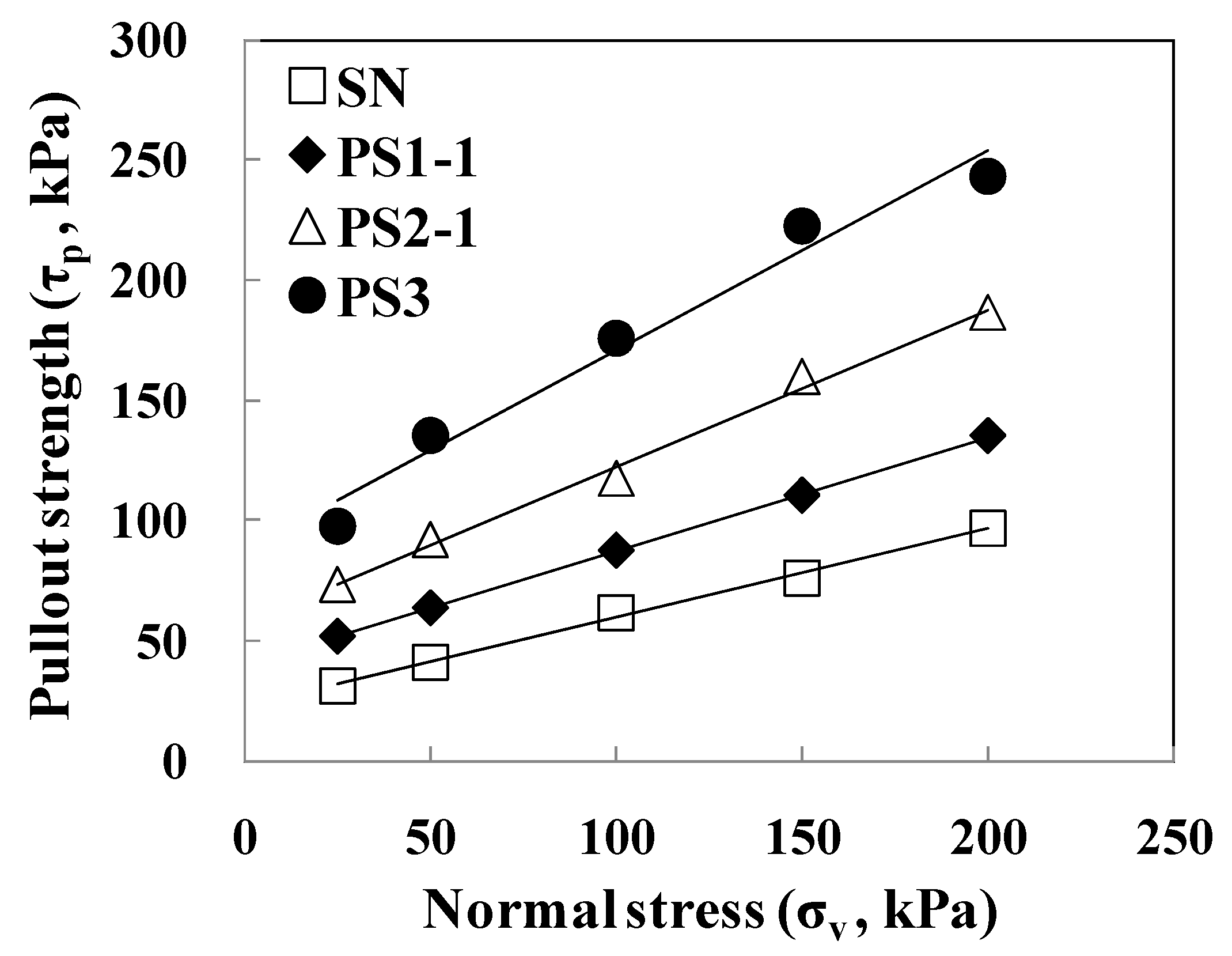
4.1. Test Results

Figure 3 shows the pullout test results of both types of reinforcement. The pullout force of case SN showed a marked peak value regardless of normal stress conditions when the front displacement was within 1.2 mm; pullout force then gradually decreased (Figure 3a). The pullout forces of PS1-1, PS2-1, and PS3 rapidly increased when front displacement was within 4 mm, and they continuously increased according to the increment of the front displacement. A number of transverse members increased, and the increment ratio of pullout force increasingly grew (Figure 3b–d). However, there were no effects with stress less than 100 kPa when transverse members were more than 2. This means that pullout resistance initially (within 4 mm) appeared only as friction resistance due to longitudinal members. Therefore, bearing resistance due to transverse members has a significant effect when front displacement and normal stress are more than 4 mm and 100 kPa, respectively.
Figure 4 shows the test results for Type B in which a location change in transverse members was installed in the same condition of normal stress (100 kPa). PS1-2 and PS1-3, in which one transverse member was installed, had a similar trend in the relationship between pullout force and pullout displacement, as shown in Figure 4a. However, the transferred bearing resistance due to pullout force on PS1-1 was less than that of other cases because the transverse member was installed at a long distance from the front wall, which is affected by wall friction. In the case of two transverse members, PS2-2, where transverse members were installed in the first and third locations, there was a large pullout force compared with that in other cases (PS2-1 and PS2-3). This means that interference was affected by the distance between transverse members when a number of transverse members were installed over two locations.

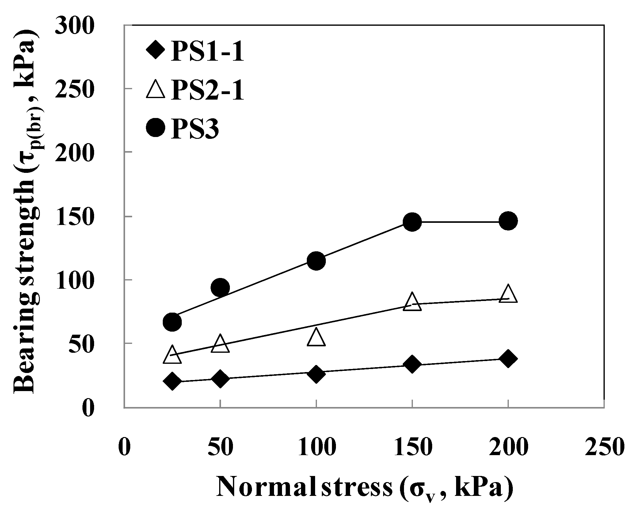
4.2. Evaluation of Pullout Strength

The pullout-resistance characteristic of inextensible reinforcement could be determined by the front displacement range as follows: (1) smooth strip, 1.2 mm, and (2) bar mats and welded wire meshes, 12–50 mm [30]. The pullout strength ( τ p ) of Types A (SN) and B (PS1-1, PS2-1, and PS3) could be calculated by using the determined displacement range. Figure 5 shows the calculated pullout strength and evaluated pullout parameters as listed in Table 3. The pullout strength of all cases had a linear increment as the increment of normal stress; the increment of normal stress and the transverse member caused greater increment. This means that the incremental effect of pullout resistance was due to the bearing resistance of transverse members. Friction strength ( τ p ( fr ) ) due to longitudinal members (SN) was subtracted from total pullout strength ( τ p ) in order to evaluate the bearing strength ( τ p ( br ) ) of transverse members in the cases of PS1-1, PS2-1, and PS3. Figure 6 shows the relationship between normal stress and bearing strength. The effect of bearing strength is increased in total pullout strength because of the increment of normal stress and transverse member. However, the incremental effect of bearing strength becomes almost constant if the normal stress is over a certain value, even though bearing strength increases as an increment of transverse members, because the bearing strength has not subsequently increased.

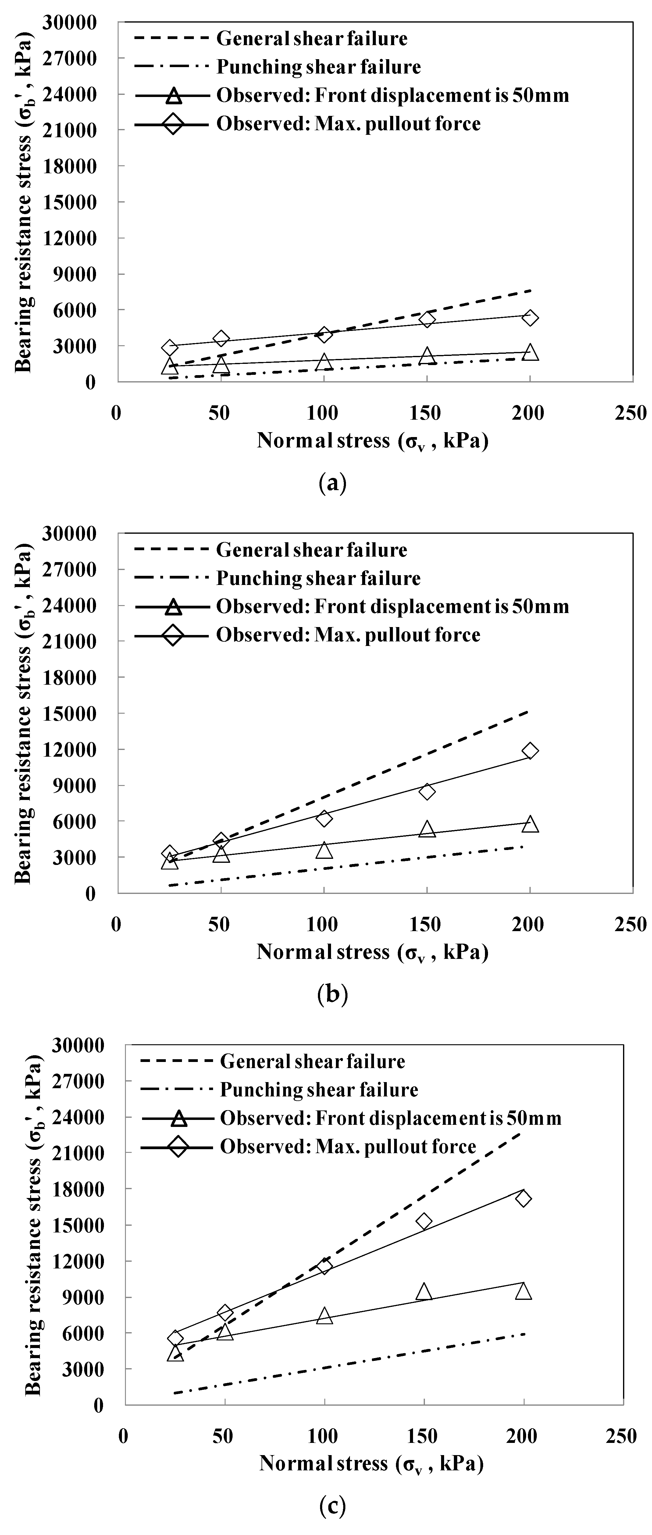
4.3. Prediction of Bearing Resistance

Figure 7 shows a comparison between the predicted values and observed results of bearing-resistance stress according to the number of transverse members. The predicted bearing resistance used in soil strength parameters is calculated from the general shear failure [19] and punching shear failure [8]. Pullout force based on the design guidelines specified by the Federal Highway Administration (FHWA) [30] was applied in order to calculate bearing-resistance stress using test results, of which the value at the front displacement was 50 mm. Pullout force was also applied to the maximal pullout force regardless of pullout force and pullout displacement, which calculate bearing-resistance stress at that point due to the transverse member.
Bearing-resistance stress in all cases, which had applied pullout force at 50 mm front displacement, was close to the general shear failure in the lower normal stress condition. However, it was close to the punching shear failure if normal stress increased because there were considerable gaps between the pullout force at 50 mm front displacement and maximal pullout force, as seen in Section 4.1. Bearing-resistance stress closed from punching shear failure to general shear failure according to the increment of the transverse member due to the small interference effect between transverse members. The interference effect showed the same results according to the set installation location of transverse members as those for the pullout force of PS2-1, which was lower than that in the other cases (see Figure 4b). On the other hand, bearing-resistance stress applied with maximal pullout force was close to general shear failure regardless of the normal stress condition or number of transverse members, as the maximal pullout force appeared when soil mass was close to shear failure.
The observed bearing-resistance stress of all cases was plotted between the lower and upper boundaries, with similar results to those of existing studies [9,24,27,31,32,33]. Existing studies are applied to reinforcements such as welded steel grids and geogrids, and the bearing resistance of these types has about 70–80% total pullout resistance [25]. However, the bearing resistance of the reinforcement used in this study had about 33%–66% in total pullout resistance according to the number of transverse members, meaning that friction and bearing resistance were evenly distributed. Therefore, the reinforcement used in this study can solve problems of existing reinforcement, such as those in the welding of welded steel grids and geogrid junctions after construction.
In the case of more than two transverse members, pullout resistance was affected by the distance between transverse members, as mentioned in Section 2.3. Figure 8 shows the relationship between bearing bond coefficient and normal stress for PS1-1, PS2-1, and PS3 considering the interference effect, which is calculated using Equation (12), and pullout force at 50 mm front displacement. The bearing bond coefficient was greatly reduced with a decrease in the number of transverse members in lower normal stress conditions. However, the reduction ratio of the bearing bond coefficient had little effect in any of the cases when the number of transverse members was decreased according to the increment of normal stress. This means that the interference effect was affected by the number of transverse members. The bearing bond coefficient was rapidly decreased within normal stress of 25–100 kPa in all cases. Subsequently, these became gradually constant, which was similar to the trend of bearing strength with a stress of over 150 kPa (Section 4.1). The reduction ratio of the bearing bond coefficient in PS3 was larger than that in the other cases because the interference effect was increased according to the increment of the transverse member, as mentioned above. This means that the increment of the interference effect was caused by the increase in the number of transverse members and normal stress.

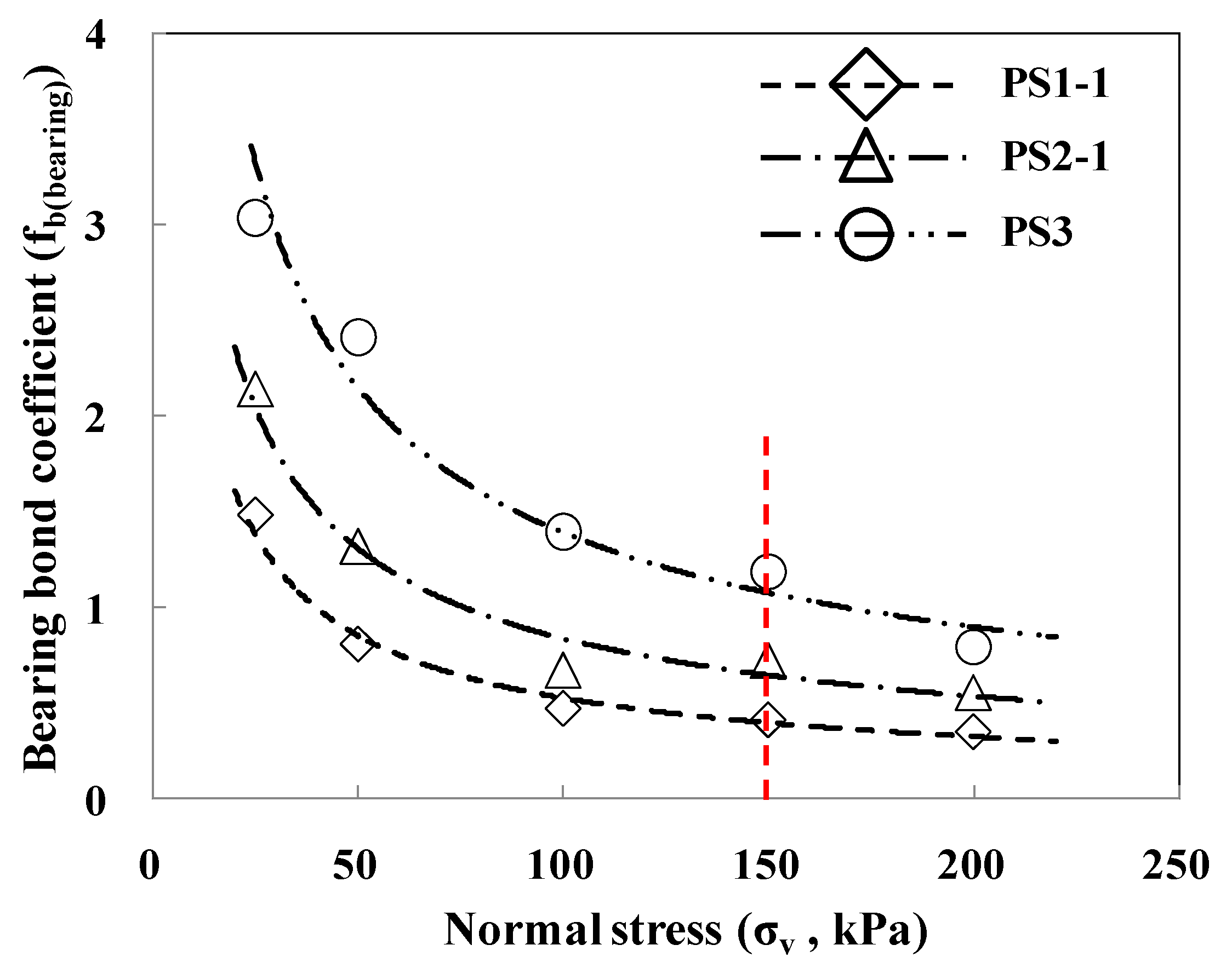
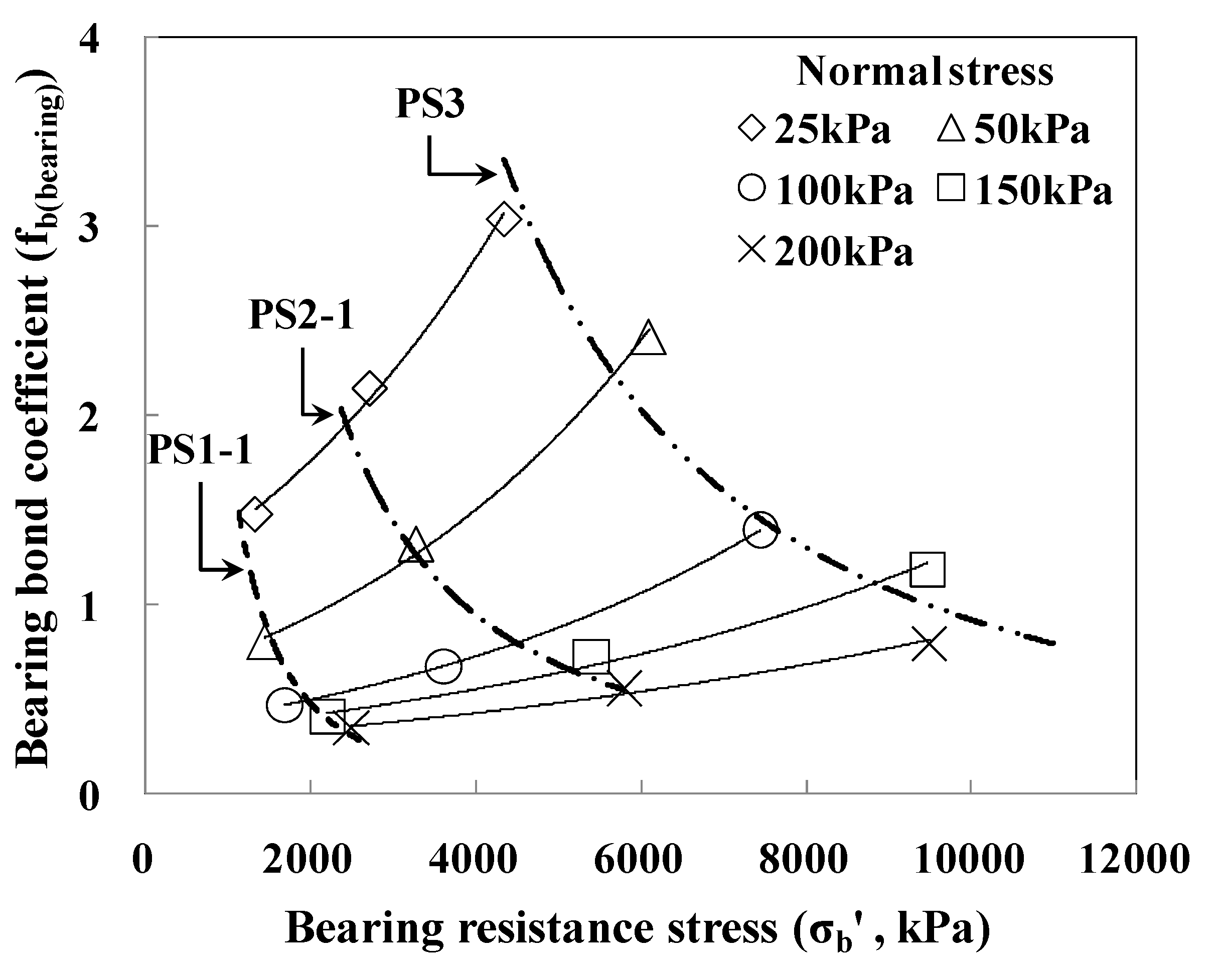
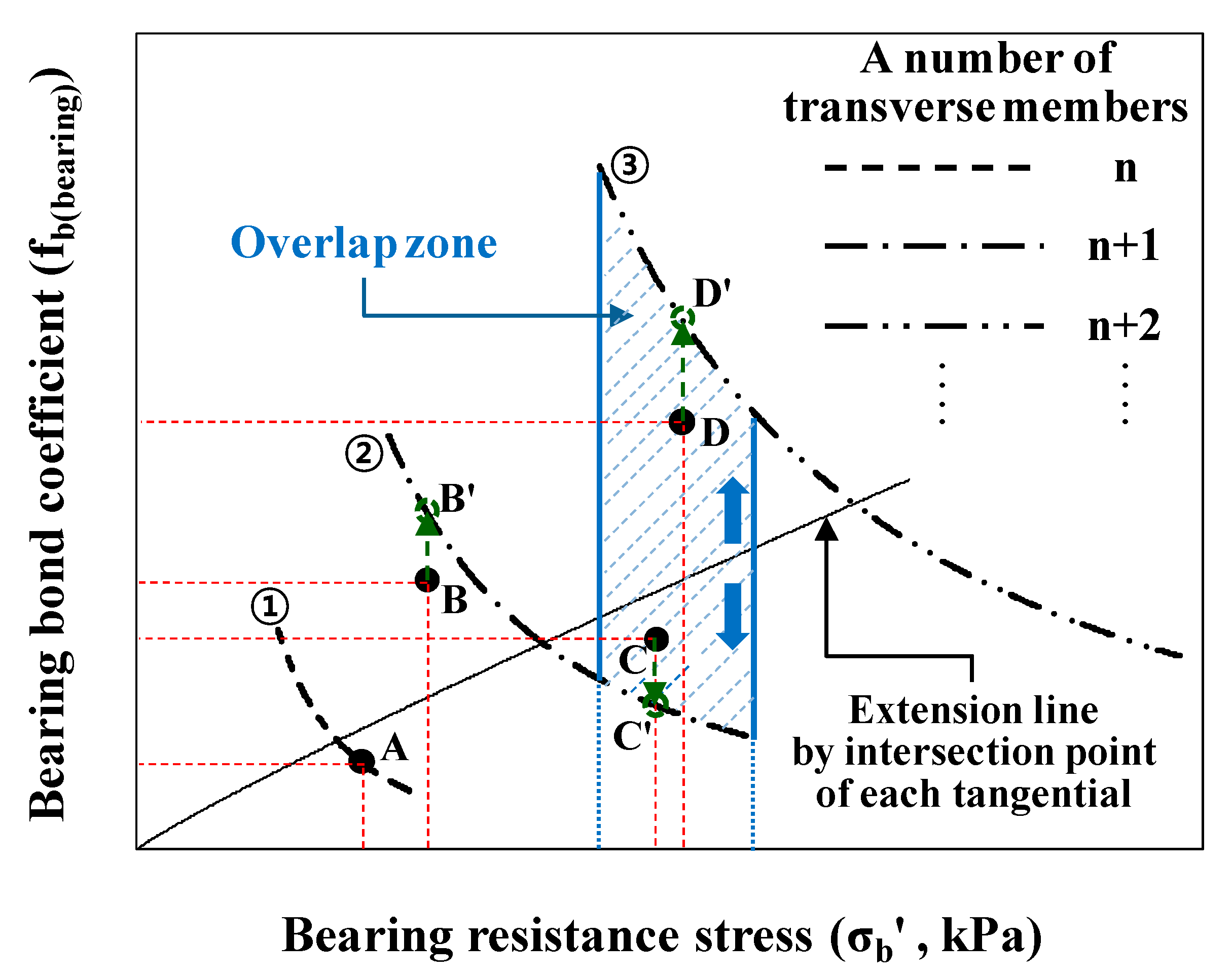
4.4. Prediction on Number of Transverse Members Considered Bearing Bond Coefficients

The relationship between bearing-resistance stress and bearing bond coefficient with the number of transverse members and normal stress is shown in Figure 9. The bearing bond coefficient was decreased according to the increment of bearing-resistance stress with the number of transverse members. Bearing-resistance stress did not increase in PS2-1 and PS3 when normal stress was above a certain value. This means that if normal stress is more than a certain level, the bearing bond coefficient and bearing-resistance stress should be considered in the application of the number of transverse members. Therefore, for transverse members, bearing-resistance stress and bearing bond coefficient due to normal stress can be found as follows.
If normal stress is higher than a certain level, bearing-resistance stress has a high value, but a number of transverse members have little effect on the bearing bond coefficient. However, the result differs for cases of lower normal stress. Meanwhile, the occurrence range of bearing-resistance stress widely varied with the increment of normal stress, but the incremental ratio of the bearing bond coefficient gradually decreased. Therefore, when predicting the number of transverse members, bearing-resistance stress and bearing bond coefficient should be considered.
In order to predict the number of transverse members needed to satisfy the required bearing resistance, a prediction method is proposed as shown in Figure 10.
The prediction method is as follows:
First, the calculated bearing-resistance stress and bearing bond coefficient, which have the same soil condition, can be plotted as shown in lines ①–③. Second, the intersectional point of each tangent line on the two sides, of which minimal and maximal normal stress is applied in lines ①–③, is extended and connected. The incremental ratio of bearing strength was decreased. Lastly, the prediction of a number of transverse members can be used to obtain the crossing point of the tangential line on the plotted line of bearing-resistance stress and bearing bond coefficient.
For example, if Points A–D for bearing-resistance stress and bearing bond coefficient are as shown in Figure 10, each point is presented as follows:
In cases marked on the plotted line (Point A) and unmarked on the plotted line or in the nonoverlap zone (Point B), a number of transverse members are selected from the plotted line and that of shift point B to B’, considering stabilization.
In the cases within the unmarked area on the plotted line and in the marked area on the overlap zone (C and D), evaluation is classified in the lower and upper zone of the solid line, which uses an extended line by the intersectional point of each tangent line in the overlap zone. That is, if the plotted point is marked on the lower zone, the prediction could be selected after the shift from C to C’; if the plotted point is marked on the upper zone, the selection could be decided after the shift from D to D’.
Therefore, the number of transverse members can easily be predicted in the nonoverlap zone. However, if the selection is within the overlap zone, the above-mentioned rational methods can be used for evaluation. That is, the stability and economic efficiency of a reinforced earth wall used in improved reinforcement can be reasonably predicted.

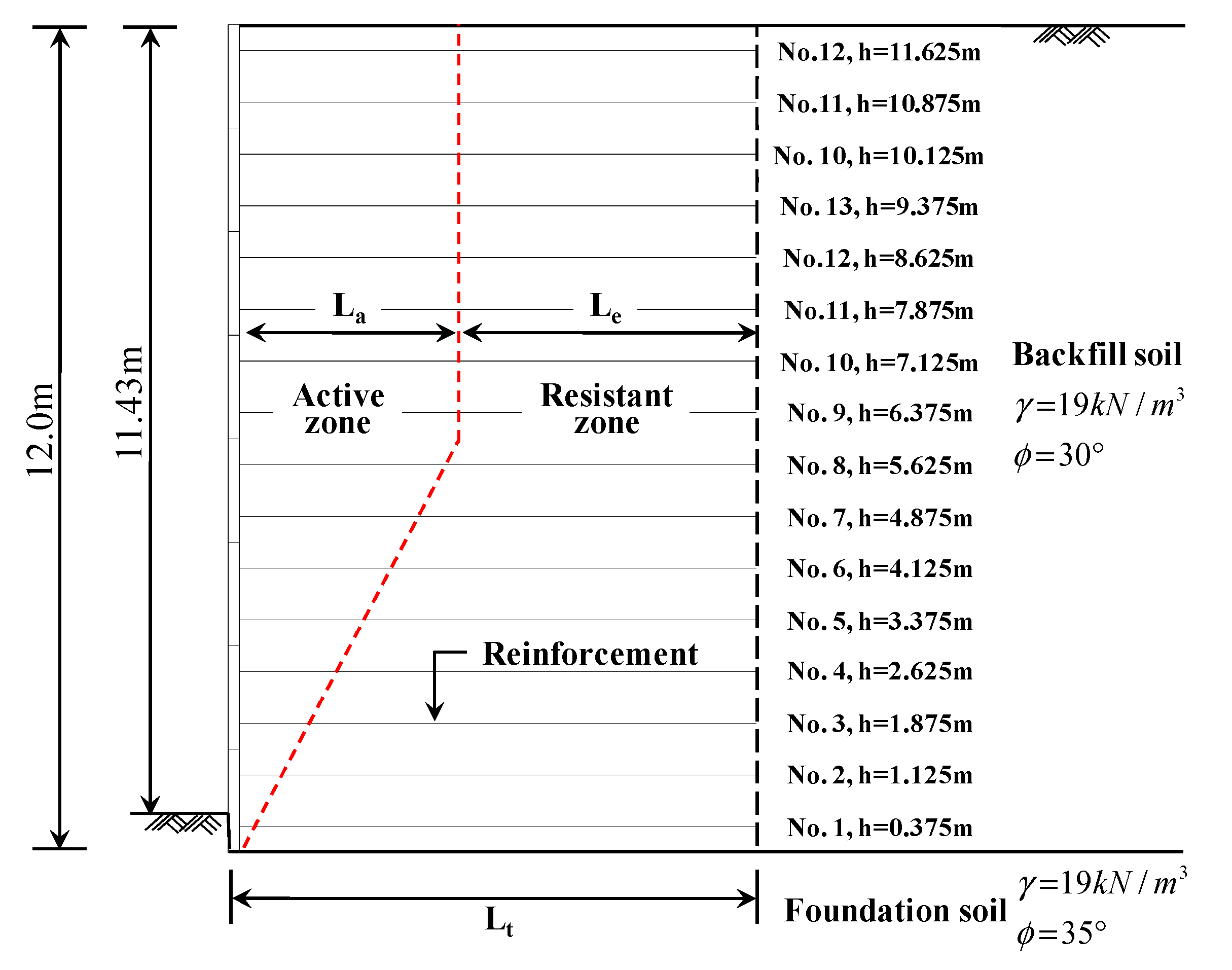
4.5. Design Case Considering Predicted Method on a Number of Transverse Members

The design case was used to verify the rationality of prediction on a number of transverse members. The design was based on design guidelines specified by FHWA [30] and applied to the same conditions. Figure 11 shows the cross-sectional view of a reinforced earth wall. Reinforcement length was 8.4 m (0.7 H), and it was designed to satisfy internal and external stability.
When transverse members were two, the general design result was compared with the design result using the predicted method. Table 4 shows the comparison between general and predicted design, confirming that the design result based on the predicted method could decrease a number of transverse members of 1st, 2nd, 15th, and 16th reinforcement. It satisfied safety factor criteria even though the safety factor was decreased. That is, the prediction for a number of transverse members could apply a bearing bond coefficient according to normal stress, and it had no effect on the stability of the reinforced earth wall. Therefore, the predicted method of transverse members could be applied as a design method of smooth steel strip with transverse members and in field design.

5. Conclusions

This study presented the pullout test results of a reinforcement that improved existing steel reinforcements on the basis of one resistance mechanism in the most pullout resistance. The improved reinforcement has smooth steel strip reinforcement with transverse members, and it had an evenly distributed friction resistance and bearing resistance. The test results obtained in this study led to the following conclusions:
(1)
The bearing-resistance effect of the total pullout resistance was not related to the effective length of reinforcement in the resistance zone because the installed quantity of the transverse member is decided by soil conditions. Therefore, total pullout resistance of the improved reinforcement should be evaluated with friction resistance on the basis of effective length due to longitudinal members and bearing resistance due to transverse members, respectively.
(2)
Bearing strength based on the resistance of transverse members had little incremental effect when the value of normal stress and the quantity of transverse members were higher than certain values because it did not increase further.
(3)
The bearing bond coefficient considering the interference effect was rapidly decreased in initial normal stress, but it gradually converged when normal stress was more than a certain value. Therefore, the increment of the interference effect was caused by the increment of the transverse member and normal stress.
(4)
Therefore, in order to predict the number of transverse members, a prediction method is proposed using the relationship between bearing-resistance stress and bearing bond coefficient due to normal stress. This is a rational method for achieving the stability and economic efficiency of reinforced earth walls using the improved reinforcement.

Author Contributions

Conceptualization, J.-G.H., K.-W.L. and G.H.; methodology, J.-G.H. and G.H.; validation, J.-Y.L., G.H. and J.P.; formal analysis, J.-G.H., G.H. and J.P.; investigation, K.-W.L., J.-Y.L. and J.P.; resources, J.-G.H., K.-W.L. and J.-Y.L.; data curation, J.-G.H., G.H. and J.P.; writing—original-draft preparation, G.H. and J.P.; writing—review and editing, J.-G.H., K.-W.L., J.-Y.L., G.H. and J.P.; visualization, J.-G.H., K.-W.L., G.H. and J.P.; supervision, J.-G.H. and K.-W.L.; project administration, K.-W.L. and J.P. All authors have read and agreed to the published version of the manuscript.

Funding

This research was supported by the MSIT (Ministry of Science and ICT), Korea, under the ITRC (Information Technology Research Center) support program (IITP-2020-2020-0-01655), the MSIT(NRF-2019R1A2C2088962) and the X-mind Corps program (2017H1D8A1030599) from the National Research Foundation (NRF) of Korea, the Human Resources Development (No. 20204030200090) of the Korea Institute of Energy Technology Evaluation and Planning (KETEP) grant funded by the Korean government.

Institutional Review Board Statement

Not applicable.

Informed Consent Statement

Not applicable.

Data Availability Statement

Data presented in this study are available on request from the corresponding author. The data are not publicly available due to data that are also part of an ongoing study.

Conflicts of Interest

The authors declare no conflict of interest.

References

  1. Yoo, C.; Jung, H.Y. Case History of Geosynthetic Reinforced Segmental Retaining Wall Failure. J. Geotech. Geoenviron. Eng. 2006, 132, 1538–1548. [Google Scholar] [CrossRef]
  2. Won, M.S.; Kim, Y.S. Internal deformation behavior of geosynthetic-reinforced soil walls. Geotext. Geomembr. 2007, 25, 10–22. [Google Scholar] [CrossRef]
  3. Bergado, D.T.; Teerawattanasuk, C. 2D and 3D numerical simulations of reinforced embankments on soft ground. Geotext. Geomembr. 2008, 26, 39–55. [Google Scholar] [CrossRef]
  4. Chen, R.H.; Chiu, Y.M. Model tests of geocell retaining structures. Geotext. Geomembr. 2008, 26, 56–57. [Google Scholar] [CrossRef]
  5. Li, A.L.; Rowe, R.K. Effects of viscous behavior of geosynthetic reinforcement and foundation soils on embankment performance. Geotext. Geomembr. 2008, 26, 317–334. [Google Scholar]
  6. Rowe, R.K.; Taechakumthorn, C. Combined effect of PVDs and reinforcement on embankments over rate-sensitive soils. Geotext. Geomembr. 2008, 26, 239–249. [Google Scholar] [CrossRef]
  7. Tatsuoka, F.; Hirakawa, D.; Nojiri, M.; Aizawa, H.; Nishikiori, H.; Soma, R.; Tateyama, M.; Watanabe, K. A new type of integral bridge comprising geosynthetic-reinforced soil walls. Geosynth. Int. 2009, 16, 301–326. [Google Scholar] [CrossRef]
  8. Jewell, R.A.; Milligan, G.W.E.; Sarsby, R.W.; Dubois, D. Interaction between Soil and Geogrids, Symposium on Polymer Grid Reinforcement in Civil Engineering; Thomas Telford Limited: London, UK, 1984; pp. 18–30. [Google Scholar]
  9. Bergado, D.T.; Hardiyatimo, H.C.; Cisneros, C.B.; Chai, C.J.; Alfaro, M.C.; Balasubramaniam, A.S.; Anderson, L.R. Pullout resistance of steel geogrids with weathered clay as backfill material. Geotech. Test. J. 1992, 15, 33–46. [Google Scholar]
  10. Bishop, J.A.; Anderson, L.R. Performance of the Welded Wire Retaining Wall; Report to Hilfiker Co.; Utah State University: Logan, UT, USA, 1979. [Google Scholar]
  11. Cho, S.D.; Shin, E.C. Application of geosynthetics and earth reinforcement technique in Korea. In Proceedings of the Special Volume, 11th ARC on Soil Mechanics and Geotechnical Engineering, Earth Reinforcement Technique in Asia, ISSMGE-TC9, Seoul, Korea, 16–20 August 1999; pp. 43–49. [Google Scholar]
  12. KGS (Korean Geosynthetics Society). Evaluation Method and Application on Geosynthetics Characteristics, Geosynthetics Short-Term Course Series I; KGS: Seoul, Korea, 2006; pp. 341–442. [Google Scholar]
  13. Jewell, R.A. Reinforcement bond capacity. Géotechnique 1990, 40, 513–518. [Google Scholar] [CrossRef]
  14. Bergado, D.T.; Chai, C.J.; Miura, N. Prediction of pullout resistance and pullout force–displacement relationship for inextensible grid reinforcements. Soils Found. 1996, 36, 11–22. [Google Scholar] [CrossRef] [Green Version]
  15. Ingold, T.S. Laboratory pull-out testing of grid reinforcements in sand. Geotech. Test. J. 1983, 6, 101–111. [Google Scholar]
  16. Jewell, R.A. Some Effects of Reinforcement on Soils. Ph.D. Thesis, University of Cambridge, Cambridge, UK, 1980. [Google Scholar]
  17. Juran, I.; Chen, C.L. Soil-geotextile pullout interaction properties: Testing and interpretation. Transp. Res. Rec. 1988, 1188, 37–47. [Google Scholar]
  18. Palmeira, E.M. Bearing force mobilisation in pull-out tests on geogrids. Geotext. Geomembr. 2004, 22, 481–509. [Google Scholar] [CrossRef]
  19. Palmeira, E.M.; Milligan, G.W.E. Scale and other factors affecting the results of pullout tests of grids buried in sand. Géotechnique 1989, 39, 511–524. [Google Scholar] [CrossRef]
  20. Peterson, L.M. Pullout Resistance of Welded Wire Mesh Embedded in Soil. Master’s Thesis, Utah State University, Logan, UT, USA, 1980. [Google Scholar]
  21. Peterson, L.M.; Anderson, L.R. Pullout Resistance of Welded Wire Mats Embedded in Soil; Report to Hilfiker Co.; Utah State University: Logan, UT, USA, 1980. [Google Scholar]
  22. Sugimoto, M.; Alagiyawanna, A.M.N.; Kadoguchi, K. Influence of rigid and flexible face on geogrid pullout tests. Geotext. Geomembr. 2001, 19, 257–278. [Google Scholar] [CrossRef]
  23. Teixeira, S.H.C.; Bueno, B.S.; Zornberg, J.G. Pullout resistance of individual longitudinal and transverse geogrid ribs. J. Geotech. Geoenviron. Eng. 2007, 133, 37–50. [Google Scholar] [CrossRef] [Green Version]
  24. Bergado, D.T.; Lo, K.H.; Chai, C.J.; Shivashankar, R.; Alfaro, M.C.; Balasubramaniam, A.S. Pullout tests using steel grids reinforcement with low-quality backfill. J. Geotech. Eng. 1992, 118, 1047–1063. [Google Scholar] [CrossRef]
  25. Matsui, T.; Nabeshima, Y.; Uchihata, K.; Han, J.G. Tensile strength of jointed reinforcements in the steel grid reinforced earth. In Proceedings of the International Conference on Ground Improvement Techniques, Macau, China, 6–8 May 1997; pp. 355–362. [Google Scholar]
  26. Matsui, T.; San, K.C.; Nabeshima, Y.; Amin, N.U. Ultimate pullout loads of steel mesh in sand. In Reports of the Osaka University; Osaka University: Osaka, Japan, 1996; Volume 46, pp. 61–73. [Google Scholar]
  27. ASTM. Standard Test Method for Measuring Geosynthetic Pullout Resistance in Soil; ASTM Book of Standards; ASTM D6706-01; ASTM: West Conshohocken, PA, USA, 2003. [Google Scholar]
  28. Kim, S.K.; Lee, E.S. Application of weathered granite soils as backfill material of reinforced earth structure. J. Korean Geotech. Soc. 1996, 12, 63–71. [Google Scholar]
  29. Kim, Y.S. Development of the Method to Determine the Weathering Degree of Decomposed Granite Soil for the Evaluation of the Engineering Properties. Ph.D. Thesis, Chung-Ang University, Seoul, Korea, 2002. [Google Scholar]
  30. Elias, V.; Christopher, B.R.; Berg, R.R. Mechanically Stabilized Earth Walls and Reinforced Soil Slopes Design and Construction Guidelines; FHWA-NHI-00-043; FHWA (Federal Highway Administration): Washington, DC, USA, 2001. [Google Scholar]
  31. Bergado, D.T.; Macatol, K.C.; Amin, N.U.; Chai, J.C.; Alfaro, M.C.; Anderson, L.R. Interaction of lateritic soil and steel grid reinforcement. Can. Geotech. J. 1993, 30, 376–384. [Google Scholar] [CrossRef]
  32. Bergado, D.T.; Shivashankar, R.; Alfaro, M.C.; Chai, J.C.; Balasubramaniam, A.S. Interaction behaviour of steel grid reinforcements in a clayey sand. Géotechnique 1993, 43, 589–603. [Google Scholar] [CrossRef]
  33. Nielsen, M.R.; Anderson, L.R. Pullout Resistance of Wire Mats Embedded in Soil; Report to Hilfiker Co.; Utah State University: Logan, UT, USA, 1984. [Google Scholar]
Figure 1. Schematic view of large-scale pullout test apparatus: (a) plan view and (b) cross-sectional view (dimensions in millimeters).
Applsci 11 02776 g001
Figure 2. Reinforcements used in this study: (a) longitudinal member, (b) transverse member, (c) reinforcement installed in test box, and (d) installation location of transverse members.
Applsci 11 02776 g002
Figure 3. Results of pullout tests: (a) SN, (b) PS1-1, (c) PS2-1, and (d) PS3.
Applsci 11 02776 g003
Figure 4. Results of pullout tests by change in installation location of transverse members (normal stress, 100 kPa): (a) number of transverse members—1 and (b) number of transverse members—2.
Applsci 11 02776 g004
Figure 5. Relationship between normal stress and pullout strength.
Applsci 11 02776 g005
Figure 6. Relationship between normal stress and bearing strength.
Applsci 11 02776 g006
Figure 7. Comparison of predicted and observed bearing-resistance stress according to number of transverse members: (a) PS1-1, (b) PS2-1, and (c) PS3.
Applsci 11 02776 g007
Figure 8. Relationship between normal stress and bearing bond coefficient.
Applsci 11 02776 g008
Figure 9. Relationship between bearing-resistance stress and bearing bond coefficient.
Applsci 11 02776 g009
Figure 10. Prediction method for number of transverse members.
Applsci 11 02776 g010
Figure 11. Cross-sectional view of design case.
Applsci 11 02776 g011
Table 1. Soil characteristics.
PropertySoil
Specific gravity, GS2.67
Plastic limit, wP (%)Nonplastic (NP)
Maximal dry unit weight, γd,max (kN/m3)18.8
Optimal water content, wop (%)14.1
Friction angle, Φ (°)35.5
Cohesion, c (kPa)8.7
Unified Soil Classification System (USCS)Well-graded sand (SW)
Table 2. Pullout testing program.
Reinforcement Type Normal Stress ( σ v ,   kPa ) Transverse-Member TypeTest Classification
Number of Transverse MembersLocation of Transverse Member
Smooth steel strip 25, 50, 100, 150, 200None-SN
Pinning jointed smooth steel strip25, 50, 100, 150, 20011stPS1-1
1002ndPS1-2
3rdPS1-3
25, 50, 100, 150, 20021st, 2ndPS2-1
1001st, 3rdPS2-2
2nd, 3rdPS2-3
25, 50, 100, 150, 20031st, 2nd, 3rdPS3
Note: test classification = longitudinal member type, a number of transverse member–location of transverse member (e.g., PS 2-1 = pinning jointed smooth steel strip, 2 (number of transverse member)–1 (1st and 2nd location of transverse member)).
Table 3. Soil characteristics.
Test ClassificationPullout Parameter
Adhesion of Soil Reinforcement
( c p ,   kPa )
Interface Friction Angle of Soil Reinforcement
(δ, °)
SN22.820.3
PS1-139.725.5
PS2-156.933.2
PS388.239.6
Table 4. Design results on pullout resistance according to predicted method.
Common Design ConditionGeneral DesignDesign Using Predicted Method
Reinforcement No.Embeded Height (m)La (m)Le (m)Safety Factor CriteriaNumber of Transverse MembersSafety Factor (FSpo)Number of Transverse MembersSafety Factor (FSpo)
10.3750.2258.175FSpo ≥ 1.521.9311.56
21.1250.6757.7251.9011.51
31.8751.1257.2751.8821.88
42.6251.5756.8251.831.83
53.3752.0256.3751.791.79
64.1252.4755.9251.751.75
74.8752.9255.4751.711.71
85.6253.3755.0251.691.69
96.3753.64.81.671.67
107.1251.671.67
117.8751.681.68
128.6251.741.74
139.3751.861.86
1410.1252.132.13
1510.8752.8111.64
Publisher’s Note: MDPI stays neutral with regard to jurisdictional claims in published maps and institutional affiliations.

