Article

A Sliding Surface for Controlling a Semi-Bridgeless Boost Converter with Power Factor Correction and Adaptive Hysteresis Band

by
José Robinson Ortiz-Castrillón
1,
Gabriel Eduardo Mejía-Ruiz
2,
Nicolás Muñoz-Galeano
1,
Jesús María López-Lezama
1,* and
Juan Bernardo Cano-Quintero
1
1
Research Group for Efficient Energy Management (GIMEL), Universidad de Antioquia (UdeA), Medellín 050010, Colombia
2
Research Group I2, Corporación Universitaria Minuto de Dios—UNIMINUTO, Bello 760101, Colombia
*
Author to whom correspondence should be addressed.
Appl. Sci. 2021, 11(4), 1873; https://doi.org/10.3390/app11041873
Submission received: 19 January 2021 / Revised: 3 February 2021 / Accepted: 16 February 2021 / Published: 20 February 2021
(This article belongs to the Special Issue Advances in Control of Power Electronic Converters)

Abstract

:
This paper proposes a new sliding surface for controlling a Semi-Bridgeless Boost Converter (SBBC) which simultaneously performs Power Factor Correction (PFC) and DC bus regulation. The proposed sliding surface is composed of three terms: First, a normalized DC voltage error term controls the DC bus and rejects DC voltage disturbances. In this case, the normalization was performed for increasing system robustness during start-up and large disturbances. Second, an AC current error term implements a PFC scheme and guarantees fast current stabilization during disturbances. Third, an integral of the AC current error term increases stability of the overall system. In addition, an Adaptive Hysteresis Band (AHB) is implemented for keeping the switching frequency constant and reducing the distortion in zero crossings. Previous papers usually include the first and/or the second terms of the proposed sliding surface, and none consider the AHB. To be best of the author’s knowledge, the proposed Sliding Mode Control (SMC) is the first control strategy for SBBCs that does not require a cascade PI or a hybrid PI-Sliding Mode Control (PI-SMC) for simultaneously controlling AC voltage and DC current, which gives the best dynamic behavior removing DC overvoltages and responding fast to DC voltage changes or DC load current perturbations. Several simulations were carried out to compare the performance of the proposed surface with a cascade PI control, a hybrid PI-SMC and the proposed SMC. Furthermore, a stability analysis of the proposed surface in start-up and under large perturbations was performed. Experimental results for PI-SMC and SMC implemented in a SBBC prototype are also presented.

1. Introduction

Many electrical devices such as motors, computers and household appliances use passive rectifiers for supplying energy to DC loads. The rectifying action usually injects lower order harmonics which increase the Total Harmonic Distortion ( T H D i ) of the current, reduces the Power Factor (PF) and worsens the energy quality of electrical grids [1,2,3]. Active rectifiers have become an attractive alternative for overcoming these problems [4,5]. They are current-controlled rectifiers used to control the current in the AC side and provide a regulated DC voltage to load, their controllers are usually designed for keeping PF and T H D i within admissible ranges (PF > 0.9 and T H D i < 5 % ) according to IEEE Std. 519 and IEC/EN 61000-3-2 [6,7].
Several active rectifiers with PFC-based on boost converter have been proposed to replace passive rectifiers [8,9,10]. Among these, SBBC is a promising topology since it stands out by reducing the number of diodes in the current path from source to load, decreasing conduction power losses and improving overall efficiency. In addition, SBBC topology has two clamped diodes that connect the source to the circuit ground, decreasing common mode noise and electromagnetic interference [8,11,12]. Due to the aforementioned reasons, the SBBC topology was selected as the topology under study of this paper.
SBBC controllers are usually based on classic cascade PI or linear controllers which feature an external voltage loop and an inner current loop that use Pulse Width Modulation (PWM) for generating the required control signals and activating power switches. However, this kind of controllers present start-up overvoltages causing instability and affecting sensitive loads [10,13,14,15,16,17]. Particularly, Kim et al. [17] made a comparative analysis for PFC of several high efficiency AC/DC boost topologies. They showed that linear controllers allow obtaining high PFs and low T H D i s; however, there are some issues to highlight: (1) DC voltage response has over peaks; (2) AC current stabilization time has a delay of several cycles in face of disturbances and load changes; and (3) the AC current waveform near zero crossing presents distortions [9,11,14]. In general terms, linear PI controllers are designed around an operating point which reduces the dynamic response in presence of large disturbances; furthermore, the dynamic performance of the controller is degraded when the operation region of the converter moves away from the equilibrium point used in the design [8,11,13]. In addition, large disturbances and extensive changes in the operation point supremely affect sensitive loads [18]. To improve the response of power systems, the use of non-linear controllers with fast response under disturbances and high working range is desirable.
SMC is a non-linear control strategy that represents a good alternative for controlling variable structure systems, as SBBCs. SMC improves the robustness against large and fast disturbances and reduces the sensitivity of the system to the variation of parameters. Furthermore, SMC deals with uncertainty in modeling parameters. Moreover, it can directly provide the switching signals of power switches by means of hysteresis modulation. Consequently, the dynamic response in closed loop is the fastest possible [19,20,21,22,23,24].
The most relevant and recently published papers related to SBBC controllers, along with their main contributions and some drawbacks, are summarized hereafter.
In [12,25], the authors proposed a hybrid PI-SMC for a SBBC that allows reducing the injection of DC current into the power network. They implemented hysteresis modulation; nonetheless, the hysteresis band amplitude is constant, obtaining a variable switching frequency which increases T H D i . Their sliding surface function consists of reducing the error between voltage and current waveforms, guaranteeing AC current and voltage in phase. SMC ensures current control for PFC when load is increasing up to 140%; however, the DC voltage presents variations of up to 13% around the equilibrium point and a delay of several grid cycles for voltage stabilization is observed. Basically, DC voltage was not considered in the sliding surface design; hence, the controller response is slow for DC bus regulation.
In [26], the authors presented an analysis between integral and double integral SMC for AC current error. Their current sliding surface with an integral component presents low steady state error and high PF; nonetheless, the AC current has high T H D i . The sliding surface with double integral reduces steady state error and T H D i ; however, a DC current component appears. For this sliding surface, DC voltage dynamic was not considered.
Sudalaimani et al. [27], Shieh and Chen [28] implemented a hybrid PI-SMC for current error reduction. In this case, the DC voltage is controlled by the external PI loop and it does not present over peaks when the load or source are disturbed or when the reference voltage is changed. Nevertheless, a slow response with delay of seconds for both AC current and DC voltage is observed.
Kessal and Rahmani [15] implemented an AC/DC converter with hybrid PI-SMC for PFC. In this case, a genetic algorithm (GA) for obtaining the sliding coefficients was developed. AC current and DC voltage errors were considered in the sliding surface design; however, the DC voltage response presents oscillations and high overvoltages in the presence of load disturbances since the SMC response was limited by the linear controller. In addition, T H D i increases due to the significant distortion produced in the AC current near zero crossing.
Mallik et al. [23] implemented an AC/DC converter based on totem-pole topology with a hybrid PI-SMC controller. AC current and DC voltage errors were considered in the sliding surface design. An integral surface of AC current and DC voltage errors were also included, reducing the steady state errors. In this case, fast responses were reached when AC current changes were incorporated; nevertheless, an external limiter for protection of power switches was required. In addition, the DC voltage presented over peaks due to the linear component of the controller.
Mohanty and Panda [18] presented an AC/DC converter with a hybrid PI-SMC controller and a PWM modulation for fixing switching frequency. The AC current and DC voltage with their corresponding integrative errors were considered. The DC voltage presented oscillations with over peaks of up to 11%, which were mitigated in several cycles of the source when the load changed, so that linear controller response was slower. Table 1 summarizes the key point of the literature review.
According to the reviewed literature, the knowledge gap consists of developing a SMC controller for SBBC that simultaneously performs Power Factor Correction (PFC) and DC bus regulation without using cascade PI or PI-SMC controllers to achieve the best dynamic behavior that removes DC overvoltages and responds fast to DC voltage changes or DC load current perturbations. For this, we propose the use of SMC with a new sliding surface with three terms that improves the following aspects: (1) A normalized DC voltage error term removes DC voltage instability in start-up and large disturbances, since the controller gives priority to the current controller component increasing robustness [29]. (2) An AC current error term implements a PFC scheme and guarantees fast current stabilization during disturbances. (3) An integral sliding term for the AC current error increases the overall system stability and reduces the stable-state error in presence of load or source disturbances. It is worth mentioning that this paper presents a rigorous deduction of the sliding mode conditions giving specific details and explaining the phenomenon of current waveform distortion that is presented in zero crossings.
Another contribution of the paper is the implementation of an Adaptive Hysteresis Band (AHB) to fix the switching frequency according to the system dynamic, which improves current waveform in zero crossing and reduces T H D i . The proposed AHB does not need PWM signals; hence, the SMC response is fast without compromising robustness.
This paper is organized as follows. Section 2 corresponds to the SMC design which includes transversality, existence and equivalent control conditions. Section 3 describes the controllers implemented in this paper: PI control, PI-SMC and SMC. Additionally, the AHB is described for PI-SMC and SMC. Section 4 presents the simulation results, including a comparative analysis of the control schemes and a detailed analysis of the proposed sliding surface illustrating its effectiveness. Section 5 presents the experimental results that demonstrate the effectiveness of the proposed SMC. Finally, conclusions are presented in Section 6.

2. Sliding Mode Control Design

In this section, the mathematical procedure for the SMC design is detailed through a five-step procedure: The first step consists of obtaining the SBBC mathematical model. The second step corresponds to the description of the proposed sliding surface for DC voltage regulation and PFC. The third step consists of the validation of the transversality condition. The fourth step is the validation of existence conditions. The fifth step is the validation of the equivalent control condition to evaluate SBBC under ideal control conditions. According to the authors of [30,31], transversality, existence and equivalent control conditions are sufficient for guaranteeing stability and convergence of the SMC.
The control objectives are as follows: (1) control the waveform of AC current, keeping it sinusoidal and in phase with AC voltage for PFC; (2) control the amplitude of the AC current ripple near zero crossing in order to reduce T H D i ; and (3) regulate the DC voltage according to load requirements.

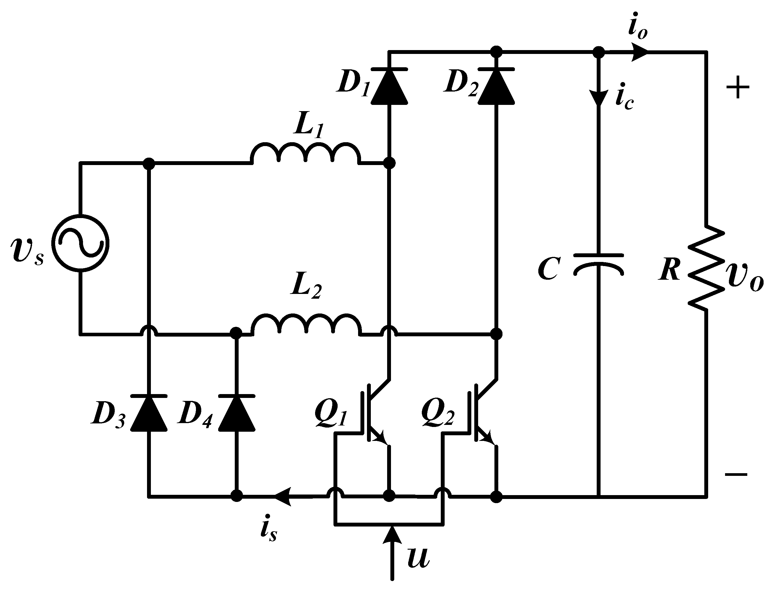
2.1. First Step: SBBC Mathematical Modeling

Figure 1 corresponds to the SBBC topology with clamped diodes. This topology has two inductors L 1 and L 2 (it is assumed that L 1 = L 2 = L ); four diodes D 1 , D 2 , D 3 and D 4 ; two power switches Q 1 and Q 2 ; and a capacitor C. The AC source is denoted by ( v s = V s s i n ( w t ) ) , while the DC load is the resistor R. L 1 , Q 1 and D 1 operate in the positive semi-cycle, while L 2 , Q 2 and D 2 operate in the negative semi-cycle. SBBC can be modeled as a boost converter for each semi-cycle and switches actuate with the control signal ( u ) ( u = 1 for closed switches and u = 0 for open switches). The mathematical model (Equations (1) and (2)) is obtained using Kirchhoff laws for both switching states. Equation (1) represents output voltage ( v o ) dynamic (DC voltage) and Equation (2) describes the dynamic behavior of the AC current ( i s ) . For a detailed description concerning the operation principle, deduction of equations and non-minimum phase issues, the work of Mejía-Ruiz et al. [32] can be consulted.
d v o d t = v o R C + ( 1 u ) i s C
d i s d t = v s L ( 1 u ) v o L

2.2. Second Step: Sliding Surface Proposal

The sliding surface ( S ) proposed in this paper is composed of the terms S 1 , S 2 and S 3 as indicated in (3). Their respective sliding coefficients are α 1 , α 2 and α 3 . S 1 corresponds to the normalized DC voltage error where V r e f is the DC voltage established as a requirement in the design process [29]. S 2 corresponds to the AC current error, where the reference current ( i r e f ) is a rectified sinusoidal signal being I r e f its amplitude, as indicated by (4). I r e f is obtained through the power balance between SBBC input and output ( P = v s i r e f = V r e f i o ) . S 3 corresponds to the integral of the AC current error used to increase system stability. This integral reduces the amplitude of oscillations in start-up for input current or in face of large disturbances.
S = α 1 v o V r e f 1 S 1 α 2 ( i s i r e f ) S 2 α 3 ( i s i r e f ) d t S 3
i r e f = 2 V r e f v o R V s I r e f | s i n ( w t ) |
Equations (1)–(3) are conveniently expressed using x 1 = ( v o / V r e f 1 ) and x 2 = i s i r e f as follows:
d x 1 d t = ( 1 u ) ( x 2 + i r e f ) C V r e f ( x 1 + 1 ) R C
d x 2 d t = v s L V r e f ( 1 u ) ( x 1 + 1 ) L d i r e f d t
S = α 1 x 1 α 2 x 2 α 3 x 2 d t
Equation (8) represents the reference current time derivative ( d i r e f / d t ) where coefficients γ 1 and γ 2 are defined as auxiliary variables. Equations (6) and (8) can be combined for deducing the dynamics of current error in (9).
d i r e f d t = 2 V r e f 2 R V s | s i n ( w t ) | γ 1 d x 1 d t 2 w V r e f 2 R V s c o s ( w t ) s i g n [ s i n ( w t ) ] γ 2 ( x 1 + 1 )
d x 2 d t = v s L + γ 1 R C γ 2 ( 1 u ) V r e f L ( x 1 + 1 ) γ 1 ( 1 u ) C V r e f ( x 2 + i r e f )

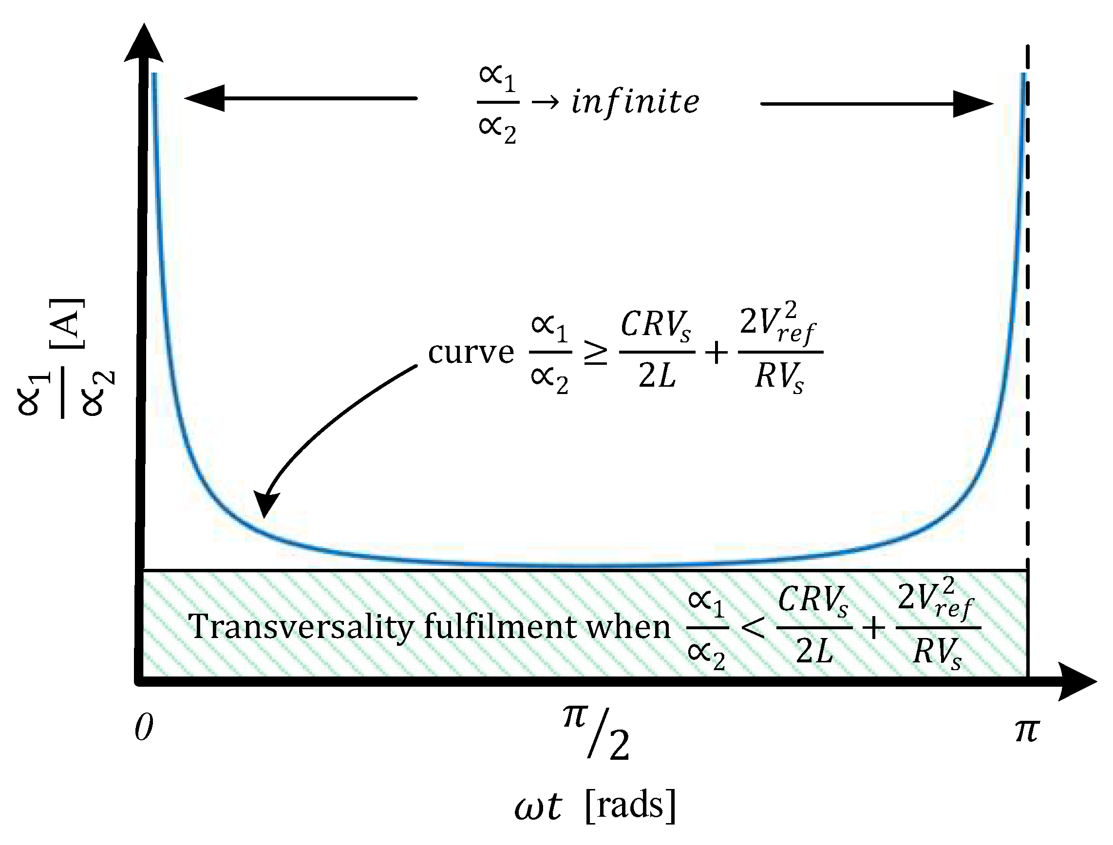
2.3. Third Step: Validation of Transversality Condition

Transversality condition allows evaluating if the SBBC can be controlled by using the control signal u according to (10). Equation (11) represents S ˙ that was obtained by deriving (7). The solution for the transversality condition is expressed by (12); this equation gives the first condition for sliding coefficients ( α 1 / α 2 ) (see (13)).
d d u d S d t 0
d S d t = S ˙ = α 1 d x 1 d t α 2 d x 2 d t α 3 x 2
d d u d S d t = α 1 C V r e f ( x 2 + i r e f ) α 2 V r e f L ( x 1 + 1 ) + γ 1 C V r e f ( x 2 + i r e f ) 0
α 1 α 2 C V r e f 2 L ( x 1 + 1 ) ( x 2 + i r e f ) + γ 1
Figure 2 is the representation of the right side of (13) (blue curve). Note that the maximum values tend to infinite when w t = 0 and w t = π , while the minimum value is presented with w t = π /2. Fulfilment of the transversality condition in the complete range of operation is given when the α 1 / α 2 ratio is less than the minimum value of the curve (see (14)). According to Figure 2, (14) better expresses the condition of (13).
α 1 α 2 < C R V s 2 L + 2 V r e f 2 R V s

2.4. Fourth Step: Validation of Existence Condition

This condition ensures the existence of a sliding mode around S = 0 , such that SBBC must remain within the sliding surface when S 0 (see (15)), guaranteeing not only S = 0 but also x 1 = x 2 = 0 . Under these conditions, the system remains controlled around the equilibrium point.
lim S = 0 + d S d t | u = 1 < 0 and lim S = 0 d S d t | u = 0 > 0
Equation (16) presents the first existence condition when the system operates over the sliding surface and the control signal ( u = 1 ) is applied for following the dynamic trajectories towards S = 0 .
lim S = 0 + d S d t | u = 1 = α 1 α 2 1 R C + γ 2 γ 1 R C ( x 1 + 1 ) α 3 α 2 x 2 v s L < 0
Figure 3a is the representation of (16), while Figure 3b is the zoom in at the extremes ( w t = 0 and w t = π ) which correspond to zero crossings. Note that d S / d t is lower than zero for almost the entire operating range, while d S / d t is greater than zero around zero crossings. Thus, for the entire operating range, regions near zero crossings correspond to unstable points and the SBBC cannot be controlled. In a strict sense of sliding mode theory, this condition is not fulfilled and sliding mode control should not be implemented. However, in practical terms, the instability of the system is produced in a short period of time, and basically this is the reason AC current deforms at zero crossing. Zero crossing deformation is not exclusive to the theory of sliding modes; this phenomenon also occurs when other control techniques are implemented [9,11,14]. In general terms, sliding mode theory allows explaining the phenomenon of zero crossing deformation. To mitigate the deformation at zero crossings, an adaptive hysteresis band based on current geometry is proposed, as described in Section 3.
Equation (17) provides the second condition for α 1 / α 2 which was obtained by evaluating (16) in system boundaries and in steady state. This condition is more restrictive than the transversality one.
α 1 α 2 < 2 w C V r e f 2 V s
Equation (18) presents the second existence condition when the system operates under the sliding surface, and the open control signal ( u = 0 ) is applied to follow the dynamic trajectories towards S = 0 . Figure 4 shows that d S / d t is greater than zero for the entire operating range. This condition is obtained considering (17).
lim S = 0 d S d t | u = 0 = α 1 α 2 γ 1 ( x 1 + 1 ) R C ( x 2 + i r e f ) C V r e f + V r e f L + γ 2 ( x 1 + 1 ) V s L α 3 α 2 x 2 > 0
Another condition that is usually verified in SMC is the hitting condition. This one is related to the existence condition and can be satisfied if the switching function is appropriately chosen [33,34]. Equation (19) corresponds to the switching function proposed in this paper. Satisfying this condition assures that, regardless of the initial condition, dynamic trajectories of the system are always towards the sliding surface. The suitable selection of the logic states of the switching function and its application in the SM control law allow changing the dynamic behavior of the system. As a consequence, for the design of the hitting condition, it is sufficient to consider state variables x 1 and x 2 , during the reaching phase. If the measured magnitude of i s is less than i r e f and v o is less than v r e f , then S is positive. In this condition, the necessary switching action required to force the system trajectories towards the sliding surface S = 0 is u = 1 , causing S ˙ < 0 . When the power switch is ON, the inductor L stores the energy supplied by the source, increasing the magnitude of i s until S = 0 . Otherwise, when the power switch is OFF, the induced voltage across L is added to v s , supplying power to the capacitor and reducing the magnitude of i s with respect to i r e f . Accordingly, the hitting condition is closely related to the way in which the switching states and hysteresis band are selected, as exhibited in (19).
u ( S ) = 1 2 ( 1 + s i g n ( S ) ) = 1 w h e n S > 0 a n d S ˙ < 0 0 w h e n S < 0 a n d S ˙ > 0

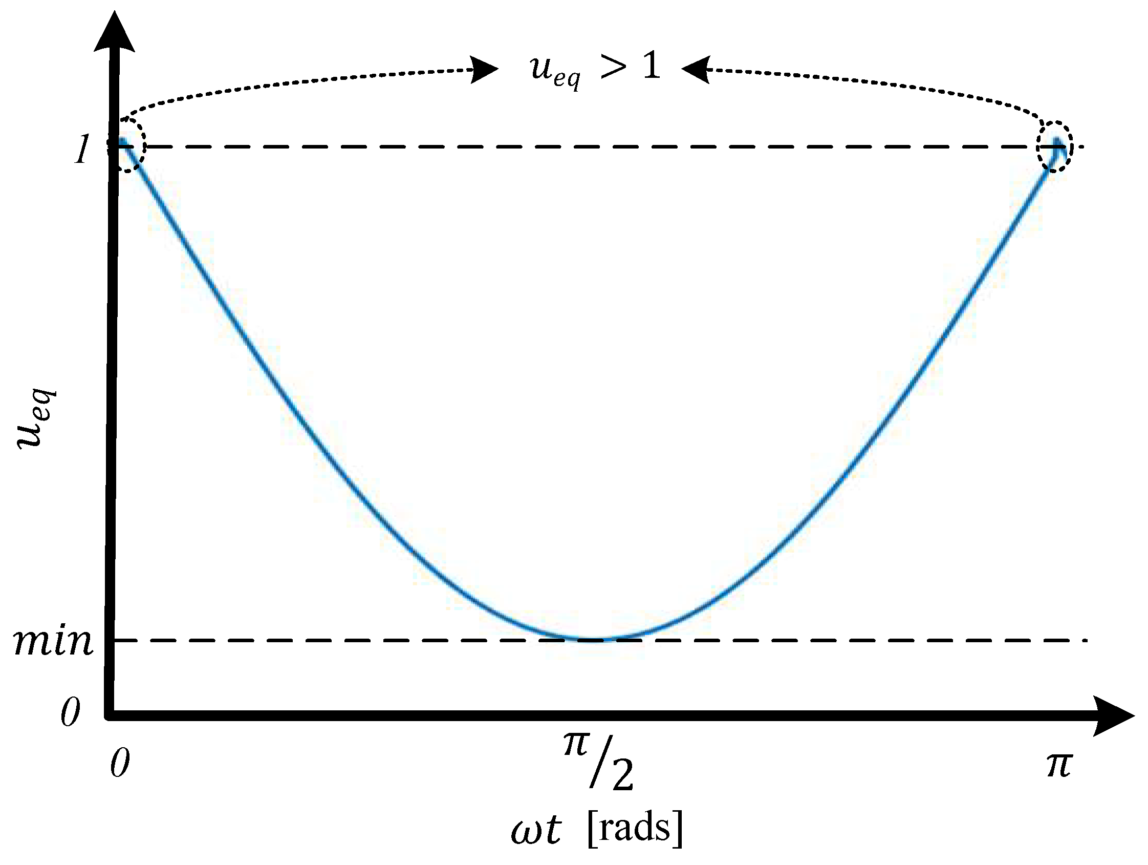
2.5. Fifth Step: Validation of Equivalent Control
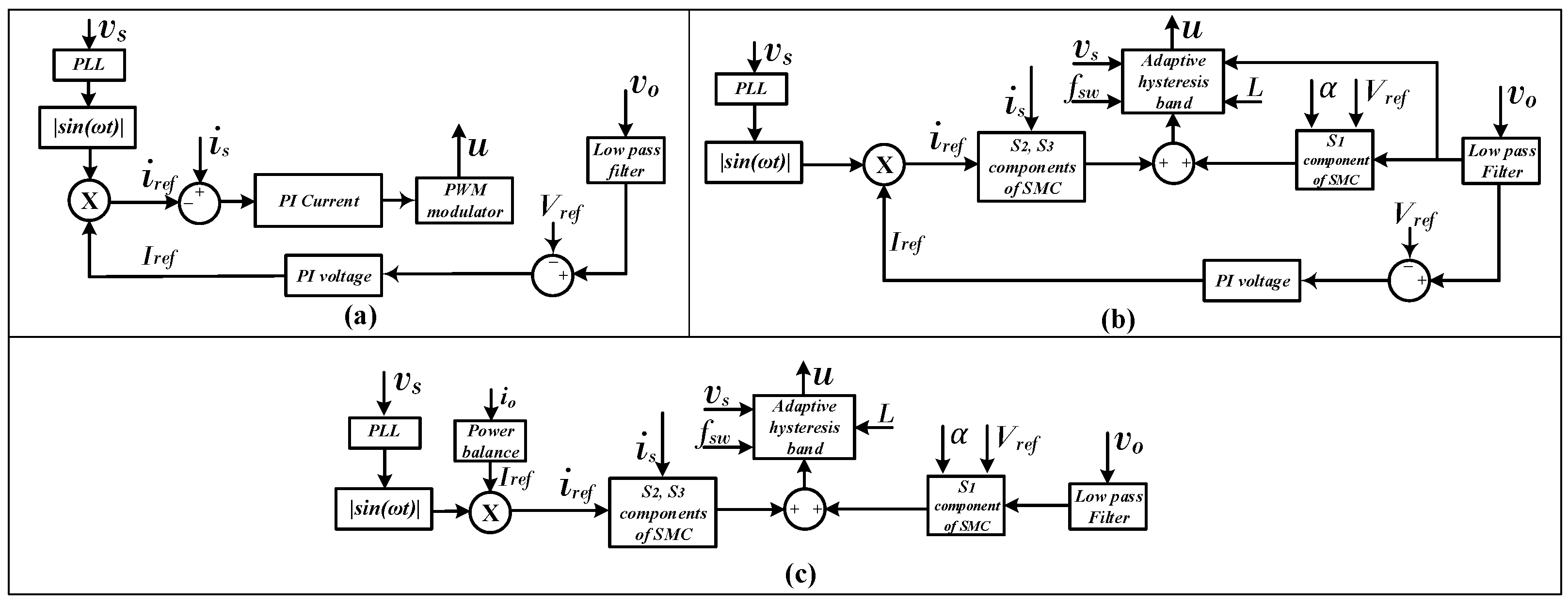
The equivalent control evaluates the system dynamics under ideal operation conditions ( x 1 = x 2 = 0 ) , assuming an infinite switching frequency and disregarding the time variation of the sliding surface ( S ˙ = 0 ). Equation (20) presents the equivalent control condition ( u e q ) obtained from (5), (9) and (11). The condition for ensuring the equivalent control ( 0 < u e q < 1 ) is presented in (21) and corresponds to the third condition for ( α 1 / α 2 ) evaluated at the system boundaries. In this case, this condition corresponds to the existence constraint found in (17), which also ensures that 0 < u e q , < 1 for the entire range of operation, except in zero crossings, as indicated in Figure 5.
u e q = 1 α 1 α 2 + R C γ 2 γ 1 ( x 1 + 1 ) R C α 3 α 2 x 2 v s L α 1 α 2 γ 1 ( x 2 + i r e f ) C V r e f V r e f L ( x 1 + 1 ) u e q ,
α 1 α 2 < 2 w C V r e f 2 V s

3. Control Schemes

Figure 6 presents the SBBC control system. The voltage waveform for obtaining the reference waveform of AC current is taken from the electrical grid by means of Phase-Locked Loop (PLL). The control system requires the measurement of v s , i s , v o and i o signals. v o and i o are filtered to remove high frequency noise. Finally, the controller calculates the control actions and generates the u signal to trigger power switches Q 1 and Q 2 .
Three control strategies are evaluated: PI, hybrid PI-SMC and the proposed SMC (see Figure 7). A classical cascade PI controller is shown in Figure 7a. The external voltage loop gives the AC current amplitude reference to internal current loop and current controller actuates by means of PWM generator. The control Scheme of the hybrid PI-SMC is depicted in Figure 7b; in this case, there is an external PI control loop for DC voltage regulation that gives the reference AC current amplitude for the internal SMC; the voltage error is considered by the SMC and an AHB is used instead of a PWM generator. The proposed SBBC control with SMC is presented in Figure 7c. This system allows controlling both DC voltage and AC current; the reference current is obtained from the power balance and the adaptive hysteresis band gives the control signal. The proposed sliding surface is used in both hybrid PI-SMC and SMC controllers in order to analyze their advantages and limitations.
The AHB is designed based on current ripple geometry according to Mejía-Ruiz et al. [35]. It has two functions: (1) smooth the current zero crossing in order to decrease T H D i ; and (2) modify the switching time according to SBBC operation point in order to fix the switching frequency. Equation (22) presents the AHB as function of v o , v s , L and f s w , while its implementation is depicted in Figure 8. The AHB calculated for each point is compared with the sliding surface. Finally, the control signal is given by a RS flip-flop. The AHB does not require PWM signals for actuating over power switches; thus, sliding mode control does not have any delay in its AC current response.
A H B = v s ( v o v s ) 2 L f s w v o

4. Simulation Results

The proposed sliding surface and its control were performed in PSIM computer simulation software. The comparative analysis for PI, hybrid SMC-PI and the proposed SMC control strategies is presented in Section 4.1, while the surface dynamic behavior at start-up is discussed in Section 4.2. The values of the system parameters are given in Table 2. The PI control parameters used in simulations are K p = 0.2 and K i = 0.2 for the voltage loop and K p = 104 and K i = 0 for the current loop. The stability analysis and control tuning were performed in sisotool (MATLAB R2020a) by means of root locus analysis together with the “Robust Response Time” tuning method. The tuning steps and criteria such as voltage overshot lower than 10% and delay between internal and external loops can be consulted in [32]. In addition, the coefficient for SMC is α = 150 , which is in the stable admissible range.

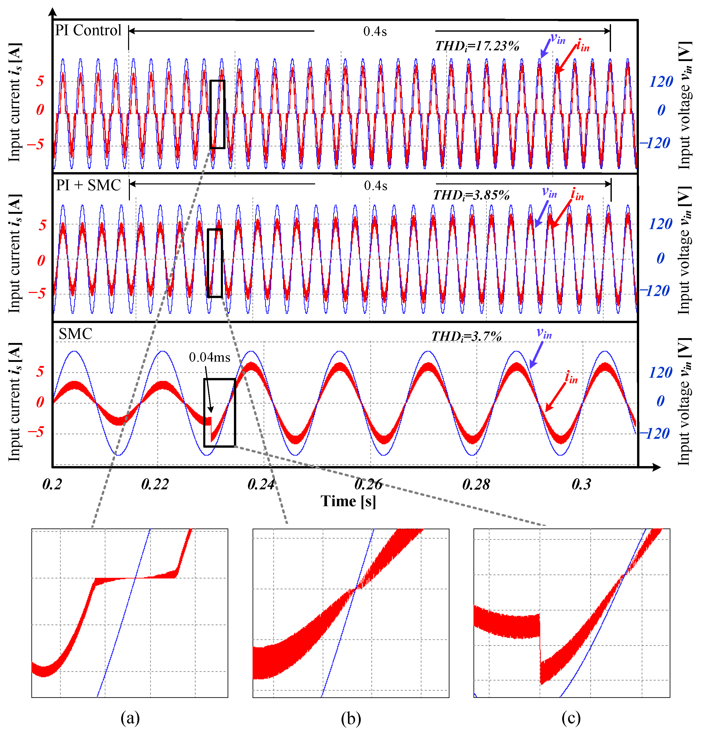
4.1. Comparative Analysis for PI, PI-SMC and SMC

The effect of load increase on SBBC performance with PI, PI-SMC and the proposed SMC controllers is analyzed. In this simulation, the DC power of the load was increased from 375 to 500 W for PI and PI-SMC controllers. In addition, to better show the performance of the SMC controller, the load was increased from 250 to 500 W. Figure 9 compares the AC current stabilization time for the three controllers. The AC current with PI controller exhibits a stabilization time of 0.4 s. This control system presents a delay between measurement and switching signal significantly degrading the waveform near zero crossing and presenting a T H D i of 17.23% (Figure 9a). For PI-SMC, the hysteresis modulation strategy improves the waveform near zero crossing of current, reducing T H D i to 3.85% (Figure 9b); nevertheless, the current stabilization (amplitude) is reached after 24 cycles, the same time as the PI controller. Finally, The proposed SMC allows regulating the AC current, rapidly responding to operation changes in only 0.04 ms. In this case, it can be observed that the current response is the fastest (Figure 9c). It can be concluded that SMC and the use of an ABH allow decreasing the T H D i to 3.7% and SMC presents the fastest response under perturbations.
Figure 10 shows the DC voltage response. The power converter with PI control (Figure 10a) takes 395.7 ms to regulate the DC voltage and presents an overvoltage of 12.75%. In comparison, PI-SMC allows reducing the overvoltage to 3.75%, maintaining the same stabilization time of the PI control (Figure 10b). This result evidences the delay caused by the PI control when it is used as external loop, limiting the transient response of the closed loop system. On the other hand, the DC voltage stabilizes in 30 ms, when the SMC strategy is used and the response exhibits a low overvoltage of 0.1% (Figure 10c). This evidences that SMC responds rapidly, protecting sensitive DC loads against overvoltages.

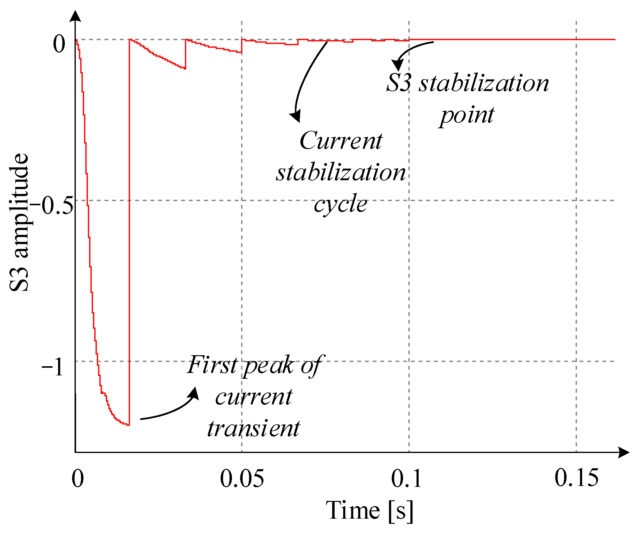
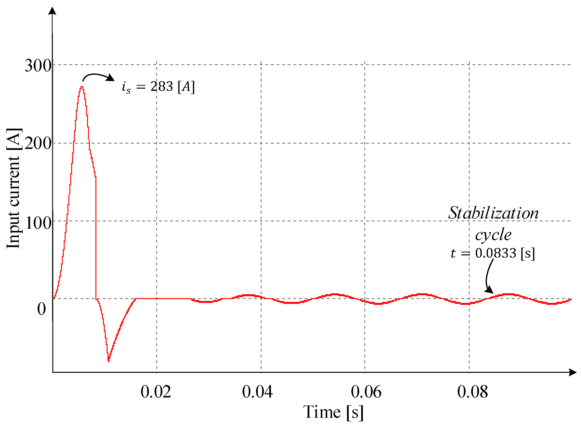
4.2. Sliding Mode Control Behavior

This section presents the stability of SMC, forcing the system to work in adverse conditions consisting on the start-up without a pre-charge of the DC bus or under large perturbations.
The response of the DC voltage in SBBC start-up is presented in Figure 11. Figure 11a shows the DC voltage without DC-bus pre-charge. Note that v o does not present instability or over peaks and it increases until reaching the stabilization point ( 400 V) in 1.52 s. The stabilization time can be modified by means of the sliding coefficient depending on the desired priority order, increasing or decreasing the response time for DC voltage or AC current. Figure 11b presents the behavior of the normalized DC voltage error ( S 1 ); initially, voltage error is bounded by its minimum value ( 1 ) . Therefore, S 1 at start-up according to the sliding coefficient value. Then, S 1 rapidly reaches the convergence point (stabilization point) and keeps sliding around S 1 = 0 . Normalization of output voltage error allows reducing the output voltage impact during large disturbances, giving priority to current control and avoiding non-minimum phase behavior [29].
The behavior of AC current in SBBC in start-up is presented in Figure 12. In Figure 12a, a transient with an over peak near 15 times the desired value is observed; nevertheless, the over peak is only presented for the first half cycle of the wave and the AC current rapidly stabilizes in a sinusoidal wave in the second grid cycle while zero crossing deformation is gradually reduced in four cycles. Figure 12b presents the behavior of AC current error ( S 2 ). Initially, S 2 also has a couple of large transient oscillations, and then the magnitude of oscillations is significantly reduced, being only evident for the first zero crossings. S 2 reaches the convergence zone oscillating near the equilibrium point in the adaptive hysteresis band. The main function of S 2 consists on properly following the AC current reference according to load requirements which permits avoiding the non-minimum phase behavior; in addition, another function of S 2 consists on performing PFC.
The behavior of S 3 in start-up is presented in Figure 13. S 3 is reset each electric grid cycle to set the cumulative error as zero. S 3 begins in zero and immediately decreases near −1.2 for the first peak; then, it increases again and reaches the convergence zone around S 3 = 0 . S 3 provides robustness under disturbances; its effect is more evident during start-up reducing oscillations before reaching the steady state.
To illustrate the impact of S 3 during start-up, Figure 14 shows the input current without using S 3 . Comparing Figure 12a and Figure 14, it can be seen that current overshoot and stabilization time are reduced when S 3 is included in the sliding surface. The stabilization of DC voltage and AC current and the convergence to zero of their errors (including integral) in SBBC start-up demonstrate the stability of the proposed sliding surface outside the operation zone (hitting condition and Lyapunov criteria).
The sliding surface dynamic behavior when a disturbance appears is shown in Figure 15. The disturbance corresponds to an increase to twice the DC load current. Figure 15 presents the sliding surface limited by the AHB in half-cycle of the AC voltage. In this case, the system is forced to be above the upper AHB, and the SMC response immediately conducts the system within the AHB, which validates the hitting condition that is observed. Concerning the existence condition, the AHB limits the speed of the response, fixing the switching frequency at 40 kHz and forcing the system to be sliding around S = 0 .
In addition, at the beginning and end of each half-cycle during zero crossings, the system is also out of the AHB; however, the SMC reacts and rapidly brings the system back into the AHB, which significantly reduces the T H D i produced in zero crossings.
Figure 16 depicts the frequency spectrum of AC current, using the proposed SMC. The energy is concentrated near the fundamental frequency (60 Hz) and the switching frequency (40 kHz). In this case, T H D i is 3.7%.

5. Experimental Results

This section presents the experimental results when the hybrid PI-SMC (Section 5.1) and the proposed SMC (Section 5.2) controllers are implemented in a SBBC. Cascade PI control was not considered since it is presented in numerous previous works and the simulations show that this controller has the worst performance. Section 5.3 shows a zero crossing comparison between PI-SMC and SMC.
The SBBC implementation is presented in Figure 17. This prototype is mainly composed of: (1) the AC supply terminals and protection system; (2) Microcontroller Printed Circuit Board (PCB) used for signal processing and control (TMS 329F28335ZJZA); (3) measurement PCBs (ACS714 and ADUM5010) for measuring AC voltage, AC current and DC voltage; (4) EMI filter for improving electromagnetic compatibility; (5) inductors L 1 and L 2 for coupling AC and DC systems; (6) power switching PCB with power switches (IGBTs) and diodes (G4PC50UD); and (7) DC bus for regulating DC voltage. SBBC Requirements and characteristics are the same as those used in the simulation results section (Table 2). A Digital scope GW Instek GDS-2204A was used (200 MHz Bandwidth, 4 Input Channel, 2 GSa/s Real-time Sampling Rate, 2 Mp Record Length) for collecting the experimental results.
The project was completely developed in C and its coding developed in Code Composer Studio (CCS) software. The control algorithm runs in two main stages: (1) i s , v s , i 0 and v 0 are sampled with 12 bits of resolution, using the Analog-to-Digital Conversion (ADC) peripheral, the computation of the sliding surface according to Equation (3) and the generation of the trigger signal u. The execution time of these control routines is regulated based on an interruption of the CPU timer of the DSP F28335 every 1 μ s. (2) The PLL algorithm is executed, the hysteresis band computation according to Equation (22) is completed, the output voltage filtering is executed to reduce the 120 Hz ripple using a notch filter and i r e f is computed based on Equation (4). When the hybrid controller is run, the PI control is also computed in this routine.

5.1. Results for PI-SMC Controller

Figure 18 presents the results when the set point of the DC voltage is changed. Initially, it was set in 400 V and a change of 20 V was made, reducing DC voltage from 400 to 380 V, as shown in Figure 18a. Then, the DC voltage set point was increased from 380 to 400 V (Figure 18b). In both cases, the DC voltage presents a stabilization time of 1.3 s with overvoltage around the stabilization point. In addition, the current amplitude slightly changes. Nonetheless, the controller keeps the AC current and voltage in phase, ensuring a P F close to 1.
Figure 19 shows the results when a load disturbance is caused. Figure 19a presents results when load decreases 25 % . In this case, an overvoltage of 22 V and a DC voltage stabilization time of 2.9 s are observed. Figure 19b depicts the results when the load increases 25 % ; SBBC presents a maximum oscillation of 18 V and the DC bus stabilizes at 1.53 s. In both tests, the AC current presents a delay of several grid cycles before reaching the stabilization point.

5.2. Results for the Proposed SMC Controller

Similar to the previous section, Figure 20 presents the results when the set point of the DC voltage is changed. Initially, it was set in 400 V and a change of 20 V was made, reducing the DC voltage from 400 to 380 V, as shown in Figure 20a. Then, the set point was increased from 380 to 400 V (Figure 20b). In both cases, the DC voltage presents a stabilization time of 1.55. In this case, it does not have any overvoltage and the P F is ensured to be close to 1. In addition, the AC current amplitude is reached in only half a cycle after the set point change; in contrast, with the PI-SMC control, the AC current amplitude is reached after several cycles.
The violet waveform in Figure 20 corresponds to v o . This result confirms that the SM controller effectively works and quickly reaches the new steady-state conditions in the presence of a significant change in operating conditions. This measure confirms the stability and robustness of the control technique proposed in this paper.
Figure 21 depicts the results for load perturbations; particularly, Figure 21a presents the results when load decreases 50 % , while Figure 21b corresponds to a load increment of 50 % . In this case, the DC voltage does not present any overvoltage or oscillations around its set point. In addition, the SBBC instantaneously responds to load changes and the current amplitude is reached in the next half-cycle. The proposed SMC control presents the fastest response among the control strategies implemented, even when the load disturbance is twice as large as the load disturbance of PI-SMC control.

5.3. Zero Crossing Comparison

A zoom for AC current results is shown in Figure 22 for the following two cases: (a) the PI-SMC with fixed hysteresis band; and (b) the SMC with the proposed AHB. In Figure 22a, ripple increments are observed just before and after the zero crossing obtaining a T H D i = 4.83 % . In Figure 22b, the zero crossing is softer than the one with fixed hysteresis band. This approach represents a better performance during zero crossing and a reduction of T H D i of 2.67 % .

5.4. Experimental vs. Simulation Results

Table 3 presents some comparisons between simulation and experimental results when load increases: (1) for Hybrid SMC-PI, the load is increased 25%; and (2) for the proposed SMC, the load is increased 50%. The stabilization time and undervoltage for v o , the cycles to reach steady state for i s and its corresponding T H D i were compared. It can be observed that there are small differences for both cases.

6. Conclusions

This paper proposes a new sliding surface for controlling a SBBC which simultaneously incorporates PFC and DC bus regulation. The proposed sliding surface contains: (1) a normalized DC voltage error term; (2) an AC current error term; and (3) an integral of the AC current error term. The surface was validated using sliding mode conditions, simulations and experimental tests. The surface was implemented for PI-SMC and SMC, and an AHB was used for fixing the switching frequency and reducing T H D i .
Simulations were performed to compare the three controllers Cascade PI, PI-SMC and SMC in terms of their dynamic behavior. When applied a DC power change of 250 W ( 50 % ), it was found that SMC presented the best performance, since the DC voltage presents the lowest stabilization time (30 ms) and practically does not present overvoltage ( 0.1 % ) which guarantees the protection of sensitive loads. In addition, the AC current has the fastest time response ( 0.04 ms) and presents the best behavior in zero crossings which reduces T H D i ( 3.7 % ).
Several simulations were also carried out concerning the behavior of the proposed sliding surface using SMC in start-up and without a pre-charge of the DC bus, forcing the system to work in adverse conditions. In this situation, the SMC responded adequately limiting DC overvoltages and stabilizing the AC current within the first half cycle despite the large start-up over current. In these simulations, the stability of the SBBC was evidenced when the SMC was implemented.
Experiments were implemented for PI-SMC and SMC considering changes in the DC voltage set-point and in the DC load current. It was found that the SBBC responds better under changes and perturbations, even though the perturbations of the SMC were more severe than the ones of the PI-SMC. Finally, zero crossing comparison showed a better behavior for SMC working with AHB, which demonstrates the rapid response of SMC under instantaneous sign changes of the sliding surface.

Author Contributions

Conceptualization, J.R.O.-C., G.E.M.-R., N.M.-G. and J.B.C.-Q.; Data curation, J.R.O.-C.; Formal analysis, J.R.O.-C., G.E.M.-R., N.M.-G. and J.B.C.-Q.; Funding acquisition, N.M.-G. and J.M.L.-L.; Investigation, J.R.O.-C., G.E.M.-R. and N.M.-G.; Methodology, J.R.O.-C., G.E.M.-R., N.M.-G. and J.B.C.-Q.; Project administration, N.M.-G.; Resources, J.R.O.-C. and G.E.M.-R.; Software, J.R.O.-C. and G.E.M.-R.; Supervision, N.M.-G. and J.M.L.-L.; Validation, J.R.O.-C. and G.E.M.-R.; Visualization, J.R.O.-C., N.M.-G. and J.M.L.-L.; Writing—original draft, J.R.O.-C.; and Writing—review and editing, G.E.M.-R., N.M.-G., J.M.L.-L. and J.B.C.-Q. All authors have read and agreed to the published version of the manuscript.

Funding

This research was funded by the Colombia Scientific Program within the framework of the so-called Ecosistema Científico (Contract No. FP44842-218-2018).

Institutional Review Board Statement

Not applicable.

Informed Consent Statement

Not applicable.

Data Availability Statement

The data presented in this study are openly available in Github repository (https://github.com/joseroca1989/appendix-paper-SMC, accessed on 19 January 2021).

Acknowledgments

The authors thank to Corporacion Universitaria Minuto de Dios—UNIMINUTO for the support received in this research. The authors also acknowledge the support from the Colombia Scientific Program within the framework of the call Ecosistema Científico (Contract No. FP44842-218-2018).

Conflicts of Interest

The authors declare that they have no conflict of interest.

References

  1. Baek, J.; Kim, J.; Lee, J.; Park, M.; Moon, G. A New Standby Structure Integrated With Boost PFC Converter for Server Power Supply. IEEE Trans. Power Electron. 2019, 34, 5283–5293. [Google Scholar] [CrossRef]
  2. Xu, H.; Chen, D.; Xue, F.; Li, X. Optimal Design Method of Interleaved Boost PFC for Improving Efficiency from Switching Frequency, Boost Inductor, and Output Voltage. IEEE Trans. Power Electron. 2019, 34, 6088–6107. [Google Scholar] [CrossRef]
  3. Bist, V.; Singh, B. An Adjustable-Speed PFC Bridgeless Buck–Boost Converter-Fed BLDC Motor Drive. IEEE Trans. Ind. Electron. 2014, 61, 2665–2677. [Google Scholar] [CrossRef]
  4. Cho, K.S.; Lee, B.K.; Kim, J.S. CRM PFC Converter with New Valley Detection Method for Improving Power System Quality. Electronics 2020, 9, 38. [Google Scholar] [CrossRef] [Green Version]
  5. Zhang, R.; Ma, W.; Wang, L.; Hu, M.; Cao, L.; Zhou, H.; Zhang, Y. Line Frequency Instability of One-Cycle-Controlled Boost Power Factor Correction Converter. Electronics 2018, 7, 203. [Google Scholar] [CrossRef] [Green Version]
  6. IEEE. Recommended Practice and Requirements for Harmonic Control in Electric Power Systems (IEEE Std 519-2014 (Revision of IEEE Std 519-1992)); IEEE: Piscataway, NJ, USA, 2014; pp. 1–29. [Google Scholar]
  7. IEEE. IEEE Recommended Practice—Adoption of IEC 61000-4-15:2010, Electromagnetic Compatibility (EMC)—Testing and Measurement Techniques—Flickermeter-Functional and Design Specifications (IEEE Std 1453-2011); IEEE: Piscataway, NJ, USA, 2011; pp. 1–58. [Google Scholar]
  8. Huang, Q.; Huang, A.Q. Review of GaN totem-pole bridgeless PFC. CPSS Trans. Power Electron. Appl. 2017, 2, 187–196. [Google Scholar] [CrossRef]
  9. Huber, L.; Jang, Y.; Jovanovic, M.M. Performance Evaluation of Bridgeless PFC Boost Rectifiers. IEEE Trans. Power Electron. 2008, 23, 1381–1390. [Google Scholar] [CrossRef]
  10. Musavi, F.; Edington, M.; Eberle, W.; Dunford, W.G. Evaluation and Efficiency Comparison of Front End AC-DC Plug-in Hybrid Charger Topologies. IEEE Trans. Smart Grid 2012, 3, 413–421. [Google Scholar] [CrossRef]
  11. Alam, M.; Eberle, W.; Gautam, D.S.; Botting, C. A Soft-Switching Bridgeless AC–DC Power Factor Correction Converter. IEEE Trans. Power Electron. 2017, 32, 7716–7726. [Google Scholar] [CrossRef]
  12. Marcos-Pastor, A.; Vidal-Idiarte, E.; Cid-Pastor, A.; Martínez-Salamero, L. Loss-Free Resistor-Based Power Factor Correction Using a Semi-Bridgeless Boost Rectifier in Sliding-Mode Control. IEEE Trans. Power Electron. 2015, 30, 5842–5853. [Google Scholar] [CrossRef] [Green Version]
  13. Tan, F.D.; Ramshaw, R.S. Instabilities of a boost converter system under large parameter variations. IEEE Trans. Power Electron. 1989, 4, 442–449. [Google Scholar] [CrossRef]
  14. Fan, J.W.; Yeung, R.S.; Chung, H.S. Optimized Hybrid PWM Scheme for Mitigating Zero-Crossing Distortion in Totem-Pole Bridgeless PFC. IEEE Trans. Power Electron. 2019, 34, 928–942. [Google Scholar] [CrossRef]
  15. Kessal, A.; Rahmani, L. Ga-Optimized Parameters of Sliding-Mode Controller Based on Both Output voltage and Input Current With an Application in the PFC of AC/DC Converters. IEEE Trans. Power Electron. 2014, 29, 3159–3165. [Google Scholar] [CrossRef]
  16. Musavi, F.; Eberle, W.; Dunford, W.G. A Phase-Shifted Gating Technique With Simplified Current Sensing for the Semi-Bridgeless AC–DC Converter. IEEE Trans. Veh. Technol. 2013, 62, 1568–1576. [Google Scholar] [CrossRef]
  17. Kim, Y.; Sung, W.; Lee, B. Comparative Performance Analysis of High Density and Efficiency PFC Topologies. IEEE Trans. Power Electron. 2014, 29, 2666–2679. [Google Scholar] [CrossRef]
  18. Mohanty, P.R.; Panda, A.K. Fixed-Frequency Sliding-Mode Control Scheme Based on Current Control Manifold for Improved Dynamic Performance of Boost PFC Converter. IEEE J. Emerg. Sel. Top. Power Electron. 2017, 5, 576–586. [Google Scholar] [CrossRef]
  19. Alsmadi, Y.M.; Utkin, V.; Haj-ahmed, M.A.; Xu, L. Sliding mode control of power converters: DC/DC converters. Int. J. Control 2018, 91, 2472–2493. [Google Scholar] [CrossRef]
  20. Montoya, D.G.; Ramos-Paja, C.A.; Giral, R. Maximum power point tracking of photovoltaic systems based on the sliding mode control of the module admittance. Electr. Power Syst. Res. 2016, 136, 125–134. [Google Scholar] [CrossRef]
  21. Sira-Ramirez, H. Nonlinear variable structure systems in sliding mode: the general case. IEEE Trans. Autom. Control 1989, 34, 1186–1188. [Google Scholar] [CrossRef]
  22. Utkin, V. Variable structure systems with sliding modes. IEEE Trans. Autom. Control 1977, 22, 212–222. [Google Scholar] [CrossRef]
  23. Mallik, A.; Lu, J.; Khaligh, A. Sliding Mode Control of Single-Phase Interleaved Totem-Pole PFC for Electric Vehicle Onboard Chargers. IEEE Trans. Veh. Technol. 2018, 67, 8100–8109. [Google Scholar] [CrossRef]
  24. El Aroudi, A.; Martínez-Treviño, B.A.; Vidal-Idiarte, E.; Cid-Pastor, A. Fixed Switching Frequency Digital Sliding-Mode Control of DC-DC Power Supplies Loaded by Constant Power Loads with Inrush Current Limitation Capability. Energies 2019, 12, 1055. [Google Scholar] [CrossRef] [Green Version]
  25. Rathore, N.; Fulwani, D.; Rathore, A.K.; Gautam, A.R. Adaptive Sliding Mode Based Loss-Free Resistor for Power-Factor Correction Application. IEEE Trans. Ind. Appl. 2019, 55, 4332–4343. [Google Scholar] [CrossRef]
  26. Harirchi, F.; Rahmati, A.; Abrishamifar, A. Boost PFC converters with integral and double integral sliding mode control. In Proceedings of the 2011 19th Iranian Conference on Electrical Engineering, Tehran, Iran, 17–19 May 2011; pp. 1–6. [Google Scholar]
  27. Sudalaimani, M.; Revathi, L.V.; Senthilkumar, N. Direct Power based Sliding Mode Control of AC-DC Converter with Reduced THD. Tehnički Vjesnik 2018, 25, 72–79. [Google Scholar]
  28. Shieh, H.J.; Chen, Y.Z. A Sliding Surface-Regulated Current-Mode Pulse-Width Modulation Controller for a Digital Signal Processor-Based Single Ended Primary Inductor Converter-Type Power Factor Correction Rectifier. Energies 2017, 10, 1175. [Google Scholar] [CrossRef] [Green Version]
  29. Chincholkar, S.H.; Jiang, W.; Chan, C. A Normalized Output Error-Based Sliding-Mode Controller for the DC–DC Cascade Boost Converter. IEEE Trans. Circuits Syst. II Express Briefs 2020, 67, 92–96. [Google Scholar] [CrossRef]
  30. Sira-Ramirez, H. Sliding motions in bilinear switched networks. IEEE Trans. Circuits Syst. 1987, 34, 919–933. [Google Scholar] [CrossRef]
  31. Sira-Ramirez, H.; Rios-Bolivar, M. Sliding mode control of DC-to-DC power converters via extended linearization. IEEE Trans. Circuits Syst. I Fundam. Theory Appl. 1994, 41, 652–661. [Google Scholar] [CrossRef]
  32. Mejía-Ruiz, G.E.; Muñoz-Galeano, N.; López-Lezama, J.M. Modeling and development of a bridgeless PFC Boost rectifier. Rev. Fac. Ing. Univ. Antioq. 2017, 82, 9–21. [Google Scholar] [CrossRef] [Green Version]
  33. Tan, S.; Lai, Y.M.; Tse, C.K.; Martinez-Salamero, L.; Wu, C. A Fast-Response Sliding-Mode Controller for Boost-Type Converters With a Wide Range of Operating Conditions. IEEE Trans. Ind. Electron. 2007, 54, 3276–3286. [Google Scholar] [CrossRef] [Green Version]
  34. Siew-Chong Tan. ; Lai, Y.M.; Tse, C.K. A unified approach to the design of PWM-based sliding-mode voltage controllers for basic DC-DC converters in continuous conduction mode. IEEE Trans. Circuits Syst. I Regul. Pap. 2006, 53, 1816–1827. [Google Scholar] [CrossRef]
  35. Mejía-Ruiz, G.E.; Muñoz-Galeano, N.; Ortiz-Castrillón, J.R. Banda de Histéresis Adaptativa para un Convertidor AC-DC Elevador sin Puente, con Correccion del Factor de Potencia y Control por Modos Deslizantes. Inf. Tecnol. 2019, 30, 283–292. [Google Scholar] [CrossRef] [Green Version]
Figure 1. Topology SBBC with clamped diodes.
Applsci 11 01873 g001
Figure 2. Graphical representation of transversality condition.
Applsci 11 01873 g002
Figure 3. d S / d t for existence condition when u = 1 . (a) Representation in the range of w t = [ 0 , π ] ; (b) Zoom in at w t = 0 and w t = π .
Applsci 11 01873 g003
Figure 4. d S / d t for existence condition when u = 0 .
Applsci 11 01873 g004
Figure 5. u e q for half cycle of electrical grid.
Applsci 11 01873 g005
Figure 6. Control system for SBBC.
Applsci 11 01873 g006
Figure 7. Block diagram of the control system: (a) classical cascade PI controller; (b) hybrid PI-SMC; and (c) proposed SMC.
Applsci 11 01873 g007
Figure 8. Adaptative hysteresis band modulator.
Applsci 11 01873 g008
Figure 9. AC current performance of: (a) PI control; (b) PI-SMC; and (c) the proposed SMC.
Applsci 11 01873 g009
Figure 10. DC voltage transient response when load increases from 250 W to 500 W, comparing the performance of (a) PI control; (b) PI-SMC; and (c) SMC.
Applsci 11 01873 g010
Figure 11. DC voltage behavior in start-up: (a) DC voltage; and (b) DC voltage error S 1 .
Applsci 11 01873 g011
Figure 12. AC current behavior in start-up: (a) AC current; and (b) AC current error S 2 .
Applsci 11 01873 g012
Figure 13. Integral of current error in start-up.
Applsci 11 01873 g013
Figure 14. Input current behavior without integral of current error in start-up.
Applsci 11 01873 g014
Figure 15. Sliding surface response for load increase.
Applsci 11 01873 g015
Figure 16. Frequency spectrum of the AC current using the adaptive hysteresis band.
Applsci 11 01873 g016
Figure 17. Semi-bridgeless boost converter for experimental tests.
Applsci 11 01873 g017
Figure 18. Experimental results with PI-SMC control for voltage set point changes: (a) DC voltage increases 20 V; and (b) DC voltage decreases 20 V.
Applsci 11 01873 g018
Figure 19. Experimental results with PI-SMC control for load changes: (a) load decreases 25 % ; and (b) load increases 25 % .
Applsci 11 01873 g019
Figure 20. Experimental results with SMC for voltage set point changes: (a) DC voltage increases 20 V; and (b) DC voltage decreases 20 V.
Applsci 11 01873 g020
Figure 21. Experimental results with SMC for load changes: (a) load increases to 50 % ; and (b) load decreases to 50 % .
Applsci 11 01873 g021
Figure 22. Zero crossing of AC current: (a) PI-SMC control; and (b) SMC control.
Applsci 11 01873 g022
Table 1. Key points of the literature review.
Ref.ContributionsDrawbacks
[12,25]Hybrid PI-SMC with constant hysteresis band.1. Variable switching frequency.
2. DC voltage not considered in the SS.
[15]GA hybrid PI-SMC1. DC voltage oscillations.
2. High DC overvoltages.
3. High T H D i near zero crossings.
[18]Hybrid PI-SMC controller (fixed frequency).1. DC voltage oscillations.
2. Slow linear control.
[23]Hybrid PI-SMC controller (Totem-pole topology).1. Protection external limiter required.
2. DC voltage over peaks.
[26]Integral and double integral SMC.1. Integral: high T H D i
2. Doble integral: DC current components.
3. DC voltage not considered in the SS.
4. DC voltage control was not implemented.
[27,28]Hybrid PI-SMC for current error reduction.1. AC-current and DC-voltage slow responses.
Table 2. Simulation parameters.
ParameterValue
Grid voltage ( v s = v i n ) 120 Vrms
Grid frequency ( f ) 60 Hz
DC bus capacitor ( C ) 2.2 mF
DC bus voltage ( V o = V r e f ) 400 V
Inductors ( L 1 = L 2 = L ) 2.2 mH
Switching frequency ( f s w ) 40 kHz
Rated power ( P o ) 500 W
Rated Load ( R ) 320 Ω
Table 3. Experimental vs. simulation: test with load increase.
CriteriaHybrid SMC-PI (Load 25%)Proposed SMC (Load 50%)
SimulationExperimentalSimulationExperimental
v o Stabilization time1.6 s1.53 s0.03 s0 s
v o Undervoltage15.5 v18 v0.4 v0 v
i s Cycles to reach steady state2427less than 1less than to 1
T H D i 4.25%4.82%3.7%2.67%
Publisher’s Note: MDPI stays neutral with regard to jurisdictional claims in published maps and institutional affiliations.

