Abstract
Increasing demand for water and energy has emphasized the significance of energy-efficient anaerobic wastewater treatment; however, anaerobic effluents still containing a large portion of the total CH4 production are discharged to the environment without being utilized as a valuable energy source. Recently, gas–liquid membrane contactors have been considered as a promising technology to recover such dissolved methane from the effluent due to their attractive characteristics such as high specific mass transfer area, no flooding at high flow rates, and low energy requirement. Nevertheless, the development and further application of membrane contactors were still not fulfilled due to their inherent issues such as membrane wetting and fouling, which lower the CH4 recovery efficiency and thus net energy production. In this perspective, the topics in membrane contactors for dissolved CH4 recovery are discussed in the following order: (1) operational principle, (2) potential as waste-to-energy conversion system, and (3) technical challenges and recent efforts to address them. Then, future efforts that should be devoted to advancing gas–liquid membrane contactors are suggested as concluding remarks.
1. Introduction
Waste-to-energy conversion technologies have been extensively studied and developed in recent decades as a sustainable waste management solution while producing additional energy. With this regard, the anaerobic digestion of wastewater has received much attention owing to its compelling advantages such as potential energy recovery in the form of biogas and low operation cost [1,2,3,4]. Of all benefits, methane (CH4) can be recognized as the valuable energy source component in the biogas, having a heating value of 55 MJ kg−1 that can be convertible to thermal and electrical energy [5]. Nevertheless, the dissolution of the produced CH4 in the liquid effluent drives the anaerobic digestion of wastewater to be less appealing than expected [6,7]. The theoretical estimation based on the Henry’s Law revealed that around 45% of the produced CH4 can be dissolved in the liquid effluent, even at 30 °C, and the portion in liquid further increases with decreasing temperature [7,8,9]. The supersaturation of biogas in the liquid, which is often observed when a mixing is not applied in the reactor, worsens this situation, causing a huge economic loss as well as a safety concern. It was reported that the supersaturation values in up flow anaerobic sludge blanket (UASB) reactors can be ranged in 1.3–6.9. However, in anaerobic membrane bioreactors (AnMBR) that are operated under proper mixing, the CH4 concentrations in the liquid are approximately at the saturation [8].
Apart from theses energy and economic losses, releasing of gaseous CH4 to the environment upon discharging the liquid effluent creates critical environment complications such as global warming. Noticeably, around 9% of global environmental CH4 emissions arises from the wastewater treatments and their related activities, which should be seriously taken into account while discharging anaerobically treated liquid effluents [6]. Moreover, the explosive nature of CH4 (lower and upper explosive limits are 4.6 and 15.8 vol % in air, respectively) necessitates the safe handling of anaerobically treated wastewater effluent in enclosed environments [10]. In general, the anaerobically treated wastewater effluent contains 10–25 mg L−1 of dissolved CH4 (D-CH4), whereas to avoid explosions in closed environments, the D-CH4 concentration should be lower than 0.14 mg L−1 [8,11]. Hence, downstream processing of anaerobically treated wastewater effluent to recover the D-CH4 is of utmost importance for phasing out the potential environmental and safety hazards while exploiting the economic gains in turn, thereby accomplishing a sustainable anaerobic wastewater treatment process.
In this respect, harvesting CH4 from both gas and liquid phases is necessary to make the process more attractive and efficient [7,9,12]. For instance, Crone et al. demonstrated the potential feasibility of self-sustaining anaerobic processes based on the recovery of the produced CH4 from both the headspace (gas phase) of the reactor and the D-CH4 in effluents [8]. Previously, we also proposed a conceptual system of energy self-sufficient anaerobic wastewater process enabled by employing a membrane contactor (MC), as shown in Figure 1 [13]. The rationale behind Figure 1 is to maximize the recovery of produced CH4 in the gaseous form at the head space as well as dissolved form in the liquid effluent (i.e., recovery of D-CH4 using an MC) followed by the conversion of CH4 to electricity using a micro turbine. The techno-economic feasibility of MC for CH4 recovery from anaerobic liquid effluents is yet to be finely investigated, since to date, no sufficient studies have been conducted at an industrial scale.
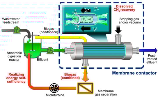
Figure 1.
Conceptual image of self-sufficient anaerobic digestion of wastewater coupled with membrane contactor (MC) technology. Adapted from [13].
Herein, we critically investigate the recent advances in gas–liquid (G-L) MCs for D-CH4 recovery from anaerobic effluents. The present report covers general operational principles of G-L MC, technical challenges, and recent progress with focus on the efforts to address the technical challenges. Finally, future prospects are presented as concluding remarks.
2. Membrane Contactors for the Recovery of D-CH4 from Anaerobic Effluents
2.1. Comparison of MC with Conventional Gas–Liquid Separation Devices
Several gas–liquid contacting processes including aeration, gas stripping, and membrane technology have been proposed for the removal of D-CH4 from effluents. The aeration (i.e., bubble columns) and gas stripping (i.e., spray tower, packed tower, tray tower, etc.) devices exploit the concept of direct contact mass transfer between liquid and gas phases. In bubble columns, the stripping gas is bubbled through the liquid-filled column, where the size and formation rate of bubbles govern the mass transfer. A high D-CH4 recovery efficiency ranging from 90 to 100% was reported by Lindberg et al. in bubble columns; however, foaming and difficulty in handling the liquids with solids were the major drawbacks [14,15]. Meanwhile, in spray towers, the nozzles at the top of the chamber generate liquid droplets from the feed, which are then directly contacted with air. The droplet size, falling height, velocity, and the type of nozzle used determine the mass transfer rate of the process [16,17]. Gloria et al. reported over 60% of D-CH4 recovery efficiency in their study with a spray tower after optimizing operation parameters [16,17]. The back mixing of recovered gas with the liquid was found to be a major issue lowering the mass transfer in the spray tower [18]. Furthermore, a high pressure is required for the formation of fine liquid droplets, leading to a high energy penalty [19]. On the contrary to spray towers, a packed tower is filled with packing materials that facilitate the mass transfer by increasing the effective mass transfer area. The liquid is supplied through spray nozzles from the top of the column, ensuring a uniform distribution over the cross-section. Flooding, channeling, and wall flow are the major drawbacks in this type of mass transfer devices, limiting the operation ranges of liquid and gas flows [20,21]. Scherer et al. reported over 90% of D-CH4 removal efficiency in a packed tower fed with groundwater [22].
As compared to the aforementioned conventional G-L separation devices, the MC technology has recently attracted much attention due to its alluring features such as high mass transfer area, safe operation (no foaming, flooding, channeling, and wall flow), independent control of gas and liquid flows, and compact design [23,24]. In an MC device, the membrane acts as a physical barrier, providing a nondispersive contact between the gas and liquid phases for mass transfer [25]. Here, the mass transfer area is well-defined at the G-L interface, and it is maintained stably compared with conventional mass transfer devices. In general, the separation effectiveness of conventional mass transfer devices is determined by the height of transfer units (HTU). As the kx/y.a (i.e., kx/y: overall mass transfer coefficient based on liquid or gas phase, a: mass transfer area per unit volume) increases, the HTU deceases, resulting in the increase of separation effectiveness [26]. Typically, for MC devices, the mass transfer area available per unit device volume ranges between 500 and 1000 ft−1, whereas those for conventional tray or packed columns are in the range of 10–100 ft−1. Hence, a significant improvement in separation efficiency can be achieved even though the overall mass transfer coefficient is almost the same or slightly lower than those of conventional G-L separation devices [23,27]. Indeed, in the CO2 absorption process, a representative application of MC, the gas absorption flux per unit device volume of MC was reported to be 2.7 times higher than that of the packed tower [28,29,30]. In addition, an economic analysis conducted by Herzog et al. revealed that by switching the CO2 capturing technology from a conventional process to a membrane absorption, 30–40% of installation and operational cost could be saved [30]. Thus, these examples imply that MC is a promising technology in both economic and energy viewpoints. Table 1 summarizes the advantages and disadvantages of MC over conventional technologies, which were discussed above.

Table 1.
Advantages and disadvantages of membrane contactor (MC) over conventional separation devices [18,19,23,24,27,31,32,33,34,35,36].
2.2. Influensive Parameters of Hollow Fiber MCs for D-CH4 Recovery
In the operation of a hollow fiber MC, many parameters such as module configuration, operational parameters, and membrane properties should be optimized. First of all, different flow geometries (i.e., liquid in lumen or liquid in shell) are known to give a significant impact on the mass transfer in MC. However, in D-CH4 recovery, the residual pollutants such as suspended solids and organics in the feed solution should also be considered together during the selection of the flow configuration. For example, Cookney et al., Henares et al., and Rongwong et al. supplied the liquid to the shell side for the high organic content anaerobic effluents such as UASB and vice versa for low organic-containing effluents such as AnMBR [13,37,38,39]. Even though the lumen side operational mode offers the better CH4 recovery efficiency, a higher risk of membrane clogging limits such operation mode. To avoid the membrane clogging issue, Sethunga et al. adopted the lumen side operation with a prefiltered UASB effluent by a filter cloth, thus achieving a higher recovery efficiency [40]. Similarly, Sanchis-Perucho et al. filtered an AnMBR effluent with a ultrafiltration membrane prior to feeding to a commercial hollow fiber MC module [41].
The conditions in the gas phase (Figure 2) are known to affect the purity of the recovered gas stream. In the studies of Henares et al. and Cookney et al., the vacuum mode (Figure 2a) promoted a greater driving force across membrane contactors, thus enhancing the overall mass transfer coefficient [11,38,39] while acquiring the product with a high CH4 concentration. However, when the MC comprises a microporous structure, a gradual decline of overall mass transfer coefficient might be anticipated due to the infiltration of water during prolonged MC operation under vacuum conditions. On the contrary, air stripping mode (Figure 2b) has been proposed to save the energy for MC operation as well as to mitigate membrane wetting. The idea is based on the fact that the biomethane recovered is burnt in the presence of air in the power generation process. Hence, if biomethane is consumed to produce electricity without a long-distance transport, this strategy would be highly beneficial. Indeed, Rongwong et al. employed a combined mild vacuum and air-stripping to maximize net energy recovery [42].
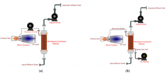
Figure 2.
(a) Vacuum mode and (b) Gas stripping mode for D-CH4 recovery and energy production. Reproduced with permission from ref [43]. Copyright 2020 Elsevier.
The most common findings in D-CH4 recovery by hollow fiber MCs are a gradual increase in overall mass transfer coefficient with an increase in liquid flowrate (L) and a negligible impact of gas flowrate (G) on the mass transfer. This is due to the dominant effect of liquid phase resistance on the overall mass transfer [44]. Nevertheless, Mc Leod et al. showed that when the G/L ratio is below a certain value, the gas phase mass transfer can play the major role in overall mass transfer [45]. The same observation was confirmed by a theoretical investigation by Sethunga et al., and they further revealed that the maximum outlet gas purity can be obtained with a lower G/L ratio reached by adjusting L rather than G [43]. Apart from the G/L ratio, it was found that the membrane inner diameter, which can change the linear velocity at a fixed G/L ratio, gives a direct impact on the CH4 transport when the liquid is fed to the lumen side [46]. When the membrane inner diameter becomes smaller, the D-CH4 recovery flux can be increased due to an increase of liquid velocity. However, a smaller membrane diameter not only causes a higher pumping energy requirement but also increases the liquid pressure, which in turn causes a larger pressure drop along the membrane. Therefore, the MC designer should wisely select the membrane diameters and recommend the operating G and L.
The membrane mass transfer coefficient is closely related to membrane morphology (i.e., porous, dense, or thin film composite) and the type of fluid inside the pores (i.e., gas or liquid). Even though porous membranes can minimize the mass transfer resistance, dense or composite membranes can also be utilized in MC applications with an aim of restricting membrane wetting and/or fouling. The mass transfer correlations for all three membrane morphologies are summarized in Table 2. However, it should be noted that these correlations may be modified based on the flow geometry and the module design [47,48].
Table 2.
Individual mass transfer correlations for counter-current flow [11,49,50].
The gas transport mechanism in a porous MC membrane is either Knudsen diffusion or viscous diffusion. Such classification is based on the dimensionless Knudsen number (Kn), which is the ratio between the mean pore radius (rp) of the membrane and the mean free path () of the gas molecule. When Kn < 1 (i.e., > rp), the gas transport mechanism is Knudsen diffusion or viscous if otherwise [51]. Meanwhile, in a dense membrane, the mass transport mechanism is governed by the solution–diffusion model, such that the permeability coefficient becomes dominant in the mass transfer coefficient calculation. The mass transfer properties of both dense and porous membranes must be considered together for composite membranes. In particular, Cookney et al. and Henares et al. investigated the applicability of dense and porous membranes for D-CH4 recovery from anaerobic reactor effluents. They ended up with the same conclusions: (1) the performance of a microporous membrane in terms of CH4 flux and recovery is better than that of a dense membrane, (2) the pore wetting limits the operation of a microporous membrane, and (3) the membrane mass transfer coefficient dominates the overall mass transfer in a dense membrane whereas the liquid phase mass transfer coefficient is dominant in microporous membranes [39,52]. Later, Cookney et al. also compared the performance of polydimethylsiloxane (PDMS) and microporous polypropylene (PP) membranes in D-CH4 recovery [39]. The rates of recovery were recorded as 92.6% and 98.9% for the nonporous and microporous membranes, respectively. In a subsequent study, Henares et al. demonstrated the limitation of the microporous membranes due to membrane fouling and wetting during a prolonged operation and thus recommended intermittent cleaning [37]. Accordingly, several studies have proposed the membrane post treatments or surface modifications to whittle down the wetting and fouling [40]. A key in the surface modification is to maintain the porosity of the membrane to keep a high CH4 flux while improving its wetting and fouling resistances. The details are discussed in the next section.
3. Technical Challenges and Recent Efforts to Address Them
Despite their great potential aforementioned, MC devices have their inherent constraints, such as membrane wetting and fouling, which limits their applicability in practical operations. More importantly, although membrane wetting and fouling seem to be two separate issues that can be possibly dealt with one by one, those two are mostly related to each other. For example, highly hydrophobic membranes that are capable of preventing pore wetting are generally vulnerable to membrane fouling [13]. Thus, many researchers have studied to mitigate or eliminate such problems to increase the overall productivity in MCs for the biomethane recovery. In this section, we enumerate recent progress on anti-wetting and anti-fouling modifications on the hollow fiber MCs.
3.1. Membrane Wetting
Membrane wetting is one of the most crucial challenges related to MC operation. Liquid intrusion into membrane pores causes pore wetting in microporous membranes. Membrane wetting, which may be either a partial or full liquid penetration, drastically affects the mass transport property in MCs. In fact, the intruded liquid forms a stagnant layer, a passive boundary inside the membrane pores, resulting in additional mass transfer resistance between the liquid and gas phases. Wang et al. reported that a 20% increase in the overall mass transfer resistance could be induced merely by 5% of pore wetting [53]. In general, membrane wetting can be triggered by a liquid pressure exceeding the critical entry pressure of a membrane (Figure 3a) and/or the capillary condensation (Figure 3b).
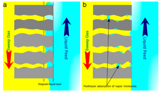
Figure 3.
Membrane wetting due to (a) a pressure above the critical entry pressure of a membrane and (b) the capillary condensation.
The Laplace–Young equation in Equation (1) adequately describes the wettability of a membrane [54]. According to this equation, the liquid entry pressure (LEP; ΔP) is influenced by the liquid surface tension (γ), the membrane pore radius (r), and the contact angle (θ). Thus, the factors that foster membrane wetting are membrane-related (i.e., hydrophobicity, membrane pore size, pore geometry, and microstructure), liquid-related (i.e., surface tension), or operation-related (i.e., liquid flow rate, vacuum pressure). Hence, one should be very careful in controlling those factors to prevent the pore wetting while operating MC systems. Several strategies have been proposed and investigated to mitigate pore wetting by improving membrane-related factors.
Several researchers have tried to make superhydrophobic membrane surfaces using fluorinated inorganic nanomaterials such as SiO2 [55,56,57,58,59,60,61,62], TiO2 [55,63,64,65], Al2O3, and ZrO2 [65]. For instance, Wongchitphimon et al. successfully fabricated a highly hydrophobic Matrimid®-fluorinated silica composite membranes exhibiting high water contact angles (WCA) ranging in 122–124°, leading to an enhanced wetting resistance [59]. The field emission scanning electron microscope (FESEM) images of the membrane surface before and after modification are shown in Figure 4a,b, respectively. The fluorinated silica nanoparticles located on the outer surface of the membrane are clearly visible. The composite membranes demonstrated a stable D-CH4 recovery flux over 300 h along with a very high CH4 flux as compared to that of a commercial PP degassing membrane. The surface modification of PVDF-HFP (Poly(vinylidene fluoride-co-hexafluoropropylene)) hollow fiber membrane with a mixture solution comprising perfluoropolyether (Fluorolink S10) and tetraethoxysilane (TEOS) was also reported [62]. The PVDF-HFP surface was firstly treated by an alkaline solution for dehydrofluorination, after which the hydroxyl groups (-OH) newly formed on the membrane surface react with TEOS and Fluorolink S10. After the surface modification, the WCA of the membrane increased from 95.5° to 127.8° with a slight decrease in pore size. In a following study, the hydrophobic modification parameters were further optimized [66]. The CH4 flux of the resulting PVDF membrane was found to be two times greater than that of the commercial PP membrane. In addition, PVDF membranes displayed a stable performance for 8 days under a test with a real anaerobic effluent owing to its excellent resistance to pore wetting.
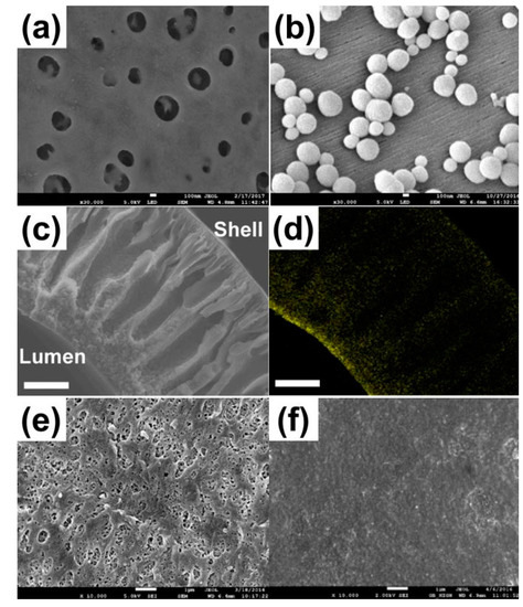
Figure 4.
Surface SEM images of (a) Matrimid® hollow fiber substrates and (b) Matrimid®-fluorinated silica composite hollow fiber membranes. Reproduced with permission from ref [46,59,63]. Copyright 2017 Elsevier. (c) Cross-sectional SEM images of polydimethylsiloxane (PDMS)-coated polyvinylidene fluoride (PVDF) membranes and (d) Si elemental mapping of PDMS-coated PVDF membranes. Reproduced with permission from ref [46,59,63]. Copyright 2019 Elsevier. FESEM images of the surfaces of (e) PVDF and (f) PVDF-fluorinated TiO2 composite hollow fiber membranes. Reproduced with permission from ref [46,59,63]. Copyright 2018 Elsevier.
On the other hand, the hydrophobic modification via chemical grafting and spray-coating on a surface of polymeric membranes has been reported as viable chemical approaches to enhance the wetting resistance. For instance, Zhang et al. reported the chemical hydrophobic modification of polymeric hollow fiber membranes, which have imide groups [67]. The ring-opening of imide groups in poly(amideimide) followed by the reaction with octadecylamine could create hydrophobic side chains, which inhibit the liquid entrance to membrane pores. The similar strategy was used to poly(etherimide), allowing the increases in both WCA and LEPw. For the case of PVDF membranes, Zhang et al. modified the membrane by a dip-coating of amorphous perfluoropolymer (Hyflon AD) on the surface [68]. Hyflon AD/PVDF composite membranes exhibited a significantly enhanced wetting resistance, along with an increased WCA. Meanwhile, polydimethylsiloxane (PDMS) has been employed as a coating material because of its hydrophobic property as well as high gas permeability. Sethunga et al. prepared two types of PDMS-coated PVDF membranes, namely lumen-modified and bulk-modified membranes and evaluated the D-CH4 recovery performance of them [69]. Lumen modified PDMS-PVDF (Figure 4c,d) membranes exhibited two times higher CH4 recovery flux than that of a commercial PP degassing membrane. According to the mass transfer analysis, the membrane resistance was only about 15% of total mass transfer resistance due to the highly porous nature of the PVDF substrate. Similarly, Li et al. modified a hydrophobic polytetrafluoroethylene (PTFE) membrane with silica nanoparticle and PDMS by a spray deposition [70]. The PDMS/silica-coated PTFE membrane exhibited a strong pore wetting resistance together with a high WCA of 158.4°. Furthermore, the PDMS/silica skin layer on the surface did not increase the mass transfer resistance significantly, owing to the high gas permeability of PDMS material.
3.2. Membrane Fouling
Membrane fouling, which is the deposition of unwanted particles, colloids, and various macromolecules on the membrane surface or inside the pores of a membrane [71], creates an additional mass transfer barrier on the membrane surface, thus lowering the CH4 permeation flux. For instance, Henare et al. observed severe membrane fouling and consequent CH4 recovery flux decline of 40% after 175-h operation of a PDMS membrane module [38]. Rongwong et al. analyzed the fouling layers deposited on hydrophobically modified PVDF membrane surfaces after the operation of MC with two types of anaerobic effluents, namely AnMBR and UASB [72]. The overall mass transfer coefficient gradually decreased with time due to membrane fouling, with UASB effluent causing more severe fouling than AnMBR effluent (Figure 5a). The fouling layer analysis revealed that the soluble microbial products such as proteins and polysaccharides form the cake layer on the membrane surface (Figure 5b), which is also typically found in the operation of MBRs. When the fouling progresses, the cake layer becomes thickened and eventually blocks the pore mouths, resulting in a gradual decrease in the overall mass transfer.
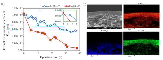
Figure 5.
(a) FESEM and energy dispersive X-ray spectroscopy (EDS) images of the cross-sectional morphology of the fouled membrane with N, F, and O elemental mappings. (b) Mass transfer analyses showing overall mass transfer coefficient (KOV) with respect to the operation time of the membrane contactor for the recovery of dissolved CH4. Reproduced with permission from ref [72]. Copyright 2019 Elsevier.
Although the fouling is an important issue that must be resolved for the practical application of MC in D-CH4 recovery, only a limited number of studies have been conducted to mitigate membrane fouling involving organic-, inorganic-, and biofouling. Nevertheless, the most common approach utilized so far is developing anti-fouling membranes. Herein, we report several recent progresses on the anti-fouling modifications of membranes that can mitigate the fouling effects during the long-term operation of G-L MC.
Introducing hydrophilicity on the membrane surface can reduce membrane fouling by decreasing an adhesion force of hydrophobic organic particles on the membrane surface. To this end, developing composite membranes coated with a thin hydrophilic layer on top of a hydrophobic membrane substrate was suggested by Rongwong et al. [13]. In their review, the possible candidates proposed for the hydrophilic layer were poly(2-hydroxyethyl methacrylate) and poly(ether block amide) [73,74]. Later, the same group successfully realized this idea by creating an anti-fouling layer on PDMS–PVDF composite membrane [40]. Prior to the surface modification, the WCA and surface streaming potential, which can be utilized as essential implications for anticipating biofouling propensity [75,76], were 120.4° and –12.8 mV respectively for the PDMS-PVDF membrane. However, after the coating with a PDMS-based amphiphilic copolymer comprising polyethylene glycol (PEG)-like segments, those values were determined as 14° and −4.1 mV [40]. Interestingly, the surface-modified membrane showed better performance during MC operation in terms of both fouling resistance and D-CH4 recovery efficiency probably due to a lower steric hindrance from the short-chain PDMS-based copolymer compared to that of the original PDMS. Consequently, the post-treatment using the amphiphilic copolymer tremendously improved the anti-fouling property of the PDMS–PVDF membrane as evidenced by the successive 7-day operation while maintaining a stable CH4 recovery flux. A similar observation was also reported by Soteropulos et al. when the membrane surface was modified with a short-chain PEG [77].
Introducing various patterns on the surface of membranes is also an effective method to prevent membrane fouling by creating turbulent hydrodynamics that imposes a high shear stress near the liquid–membrane surface [13]. Although this strategy has not yet been implemented in MC for D-CH4 recovery, herein, we want to introduce some recent examples from relevant membrane technology. The primary advantage of patterning on the membrane surface is that the fouling resistance is created without introducing additional layers on top of the membrane surface [78]. Ding et al. showed that surface patterning using nanoimprint lithography (NIL) on flat-sheet ultrafiltration (UF), microfiltration (MF), and thin-film composite membranes could induce antifouling characteristics on the membranes [79]. By comparing both patterned and unpatterned membranes, it was confirmed that the presence of the surface patterning increased shear stress at the membrane surface, thus mitigating the accumulation of colloids and protein-like macromolecules. Furthermore, Xie et al. found that fabricating a line-shape nanostructure on the surface of the membrane not only minimized the water flux decline but also reduced the deposition of foulants in membrane distillation (MD) [80]. Comprehensive analysis revealed that the patterned membrane exhibited a much lower adhesion force between the membrane surface and protein foulants as compared to the pristine membrane. Won et al. also suggested that mitigating fouling propensity can be achieved by introducing patterned morphology on the membrane surface [81]. The patterned morphology such as prism and pyramid on a cross-flow MF system enhanced hydraulic resistance on the membrane surface, inducing a local turbulence that inhibits biofouling on the membrane surfaces.
Apart from all these efforts to fabricate anti-fouling membranes, the low fouling could also be achieved by designing novel MC systems. As shown in Figure 6, Li et al. proposed a novel approach to recover D-CH4 from a model anaerobic effluent by using an omniphobic membrane [82]. Unlike conventional membrane contactor systems, a non-polar (highly methane soluble), non-volatile organic solvent was utilized instead of sweeping gas or vacuum to create the driving force for MC operation. The difference of methane solubility in between the feed solution and the solvent drives the transport D-CH4 from the feed, achieving over 90% of methane recovery at a temperature range of 15–35 °C. In the later work, AnMBR effluent was used as the feed solution to evaluate D-CH4 recovery performance of the solvent-based membrane contactor (SMC) under realistic conditions [83]. The solvent-derived transfer of methane via the omniphobic membrane contactor showed over 90% methane recovery during the 24-h operation. More importantly, the absence of water flux across the membrane could prevent any accumulation of organic foulants on the membrane surface.
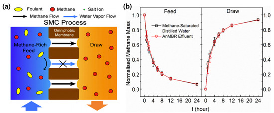
Figure 6.
(a) Schematic illustrations of the solvent-based membrane contactor (SMC) process for methane extraction and (b) time traces of normalized methane mass in the feed and draw solutions at 25 °C for SMC experiments. Reproduced with permission from ref [83]. Copyright 2020 Elsevier.
Once a membrane is fouled, despite all the efforts for anti-fouling, the cleaning should be conducted to restore the original membrane performance. Although the most primitive and effective method of removing membrane fouling is chemical cleaning, it should be considered as the last option, since the cleaning chemicals can alter the membrane surface properties. However, physical cleaning such as back washing or flushing with water can be recommended. The physical cleaning is known to be most effective when the foulants are weakly bound to the membrane surface. To this end, the aforementioned hydrophilic anti-fouling coating on the membrane surface is once again a very effective strategy in controlling membrane fouling. Indeed, Sethunga et al. demonstrated that the membrane coated with a hydrophilic anti-fouling layer could be readily cleaned by a flushing with tap water, after which the D-CH4 flux was returned back to the original flux of fresh membrane [40].
It is worth noting that all membranes have a certain lifetime after which a replacement with a new one is inevitable. Owing to the growing concern on the generation of solid waste from used membranes, biodegradable membranes have also been developed in recent years. Such membranes were successfully fabricated by utilizing cellulose nanofiber composite [84], chitosan [85], and polycaprolactone [86]. Accordingly, in the future, membrane contactors with high performance and sufficient biodegradability should be targeted for the sustainable management of the overall system.
4. Net Energy Production in MCs
Maximizing the biomethane recovery from anaerobic effluents and thus harvesting the useful energy is the major goal of utilizing membrane contactors. As mentioned in the previous sections, the biomethane recovery efficiency heavily depends on both membrane inherent parameters and operating parameters. A number of studies have reported the methane recovery efficiencies of hollow fiber MCs to demonstrate the potential benefits of the processes. More importantly, economic analysis in terms of net energy production has also been conducted in some studies by considering the cost and energy required for the operation of MCs. For example, Rongwong et al. conducted economic analysis based on the modelling data of a MC comprising hydrophobic hollow fiber membranes [42]. They predicted positive net energy production values (ENET), which can be further increased by optimizing the operation conditions. Later, Sethunga et al. analyzed the percent methane recoveries from AnMBR and UASB effluents for a MC employing a surface-modified PDMS–PVDF membrane [40]. The membrane performance was maintained for 7 days with a mild fouling propensity when the liquid velocity was fixed at 0.06 m s−1 under vacuum operation. In addition to the methane recovery efficiency, they also carried out the economic analysis and provide ENET values as summarized in Table 3. Although the methane recovery performance of the PDMS-only membrane was found to be the greatest among the four candidates, the recovery efficiency of the PDMS-only membrane was significantly degraded due to the membrane fouling after 3 days. Eventually, the membrane with anti-fouling layer (PDMS-co-P1) could extract 3% more energy than the PDMS-only membrane, implying that the control of membrane fouling is highly important to secure the net energy production. It is noteworthy that such difference in net energy production would become greater and more evident during the long-term operations.
Table 3.
Comparison of the membranes tested.
5. Future Directions
Even though the G-L MC system is a promising technology to recover D-CH4 from anaerobic effluents and thus produce useful energy from wastes, technical challenges have limited its large-scale practical applications. To capitalize the potential benefits of MC systems in practical applications, the following aspects should be investigated and improved in future studies.
- The development of anti-wetting and anti-fouling membranes is an essential component of the utilization and application of membrane contactors. Membrane contactors without fouling and wetting resistances require frequent membrane cleaning and membrane replacements, which eventually lower the economic feasibility of the process. Thus far, many studies have been carried out by using commercially available MC membranes such as PP and PDMS membranes, and the membrane fouling was not the major focus in most of studies. Noticeably, the biofouling that occurred in the D-CH4 recovery process would be hard to tackle, as microorganisms in anaerobic effluents can even foul the surface of the hydrophilic layer at a prolonged operation [13]. In addition, the anti-wetting property of the membrane should be addressed properly, considering the realistic conditions, including the fouling effect. For example, the surface property of the membrane can be altered by the deposition of a fouling layer, although a hydrophobic membrane surface was successfully created. Accordingly, it is recommended to develop high-performance membranes possessing both anti-wetting and anti-fouling properties together.
- Switching lab-scale to large-scale testing is needed to acquire more reliable data. Both membrane and operation parameters should be optimized together to maximize the net energy production in large-scale MC operation. Especially, the membrane module should be effectively designed in such a way that both liquid and gas streams are uniformly distributed inside the module, since ineffective flow stream often limits the overall performance of large-scale hollow fiber module. It is worth noting that a success in a lab-scale test using a few pieces of lab-made hollow fibers cannot guarantee the success in a large-scale practical operation. The operation parameters that are effective in a large-scale system would also be different from those found in a lab-scale system.
- More rigorous economic analysis is required based on data from large-scale operations under realistic conditions to provide more convincing evidence to potential users. In such analysis, practical parameters that must be involved in a long-term operation at real conditions, such as any pretreatments required for membrane fouling control, periodic membrane cleaning, and membrane replacement, must be taken into account.
Author Contributions
Conceptualization, T.-H.B.; methodology, Y.L. and K.H.Y.; validation, D.S.; investigation, Y.L. and K.H.Y.; writing—original draft preparation, Y.L. and K.H.Y.; writing—review and editing, D.S. and T.-H.B.; supervision, T.-H.B.; project administration, T.-H.B.; funding acquisition, T.-H.B. All authors have read and agreed to the published version of the manuscript.
Funding
This work was supported by the Materials & Components Technology Development Program (Project number: 20011128) funded by the Ministry of Trade, Industry & Energy (MOTIE, Korea).
Institutional Review Board Statement
Not Applicable.
Informed Consent Statement
Not applicable.
Data Availability Statement
Not Applicable.
Conflicts of Interest
The authors declare no conflict of interest.
References
- Lofrano, G.; Brown, J. Wastewater management through the ages: A history of mankind. Sci. Total Environ. 2010, 408, 5254–5264. [Google Scholar] [CrossRef] [PubMed]
- Puyol, D.; Batstone, D.J.; Hülsen, T.; Astals, S.; Peces, M.; Krömer, J.O. Resource recovery from wastewater by biological technologies: Opportunities, challenges, and prospects. Front. Microbiol. 2017, 7, 2106. [Google Scholar] [CrossRef] [PubMed]
- Chan, Y.J.; Chong, M.F.; Law, C.L.; Hassell, D. A review on anaerobic–aerobic treatment of industrial and municipal wastewater. Chem. Eng. J. 2009, 155, 1–18. [Google Scholar] [CrossRef]
- Cakir, F.; Stenstrom, M. Greenhouse gas production: A comparison between aerobic and anaerobic wastewater treatment technology. Water Res. 2005, 39, 4197–4203. [Google Scholar] [CrossRef] [PubMed]
- Noor, M.; Wandel, A.P.; Yusaf, T. Design and development of mild combustion burner. J. Mech. Eng. Sci. 2013, 5, 662–676. [Google Scholar] [CrossRef]
- Velasco, P.; Jegatheesan, V.; Othman, M. Recovery of dissolved methane from anaerobic membrane bioreactor using degassing membrane contactors. Front. Environ. Sci. 2018, 6, 151. [Google Scholar] [CrossRef]
- Liu, Z.-H.; Yin, H.; Dang, Z.; Liu, Y. Dissolved methane: A hurdle for anaerobic treatment of municipal wastewater. ACS Publ. 2014. [Google Scholar] [CrossRef]
- Crone, B.C.; Garland, J.L.; Sorial, G.A.; Vane, L.M. Significance of dissolved methane in effluents of anaerobically treated low strength wastewater and potential for recovery as an energy product: A review. Water Res. 2016, 104, 520–531. [Google Scholar] [CrossRef]
- Souza, C.; Chernicharo, C.; Aquino, S. Quantification of dissolved methane in UASB reactors treating domestic wastewater under different operating conditions. Water Sci. Technol. 2011, 64, 2259–2264. [Google Scholar] [CrossRef]
- Kundu, S.; Zanganeh, J.; Moghtaderi, B. A review on understanding explosions from methane–air mixture. J. Loss. Prev. Process. Ind. 2016, 40, 507–523. [Google Scholar] [CrossRef]
- Cookney, J.; Cartmell, E.; Jefferson, B.; McAdam, E. Recovery of methane from anaerobic process effluent using poly-di-methyl-siloxane membrane contactors. Water Sci. Technol. 2012, 65, 604–610. [Google Scholar] [CrossRef] [PubMed]
- Bandara, W.M.; Satoh, H.; Sasakawa, M.; Nakahara, Y.; Takahashi, M.; Okabe, S. Removal of residual dissolved methane gas in an upflow anaerobic sludge blanket reactor treating low-strength wastewater at low temperature with degassing membrane. Water Res. 2011, 45, 3533–3540. [Google Scholar] [CrossRef] [PubMed]
- Rongwong, W.; Lee, J.; Goh, K.; Karahan, H.E.; Bae, T.-H. Membrane-based technologies for post-treatment of anaerobic effluents. NPJ Clean Water 2018, 1, 1–11. [Google Scholar] [CrossRef]
- Mena, P.; Ferreira, A.; Teixeira, J.; Rocha, F. Effect of some solid properties on gas–liquid mass transfer in a bubble column. Chem. Eng. Process. Process Intensif. 2011, 50, 181–188. [Google Scholar] [CrossRef]
- Lindberg, A.; Rasmuson, Å.C. Selective desorption of carbon dioxide from sewage sludge for in situ methane enrichment—part I: Pilot—Plant experiments. Biotechnol. Bioeng. 2006, 95, 794–803. [Google Scholar] [CrossRef] [PubMed]
- Glória, R.; Motta, T.; Silva, P.; Costa, P.d.; Brandt, E.; Souza, C.; Chernicharo, C. Stripping and dissipation techniques for the removal of dissolved gases from anaerobic effluents. Braz. J. Chem. Eng. 2016, 33, 713–721. [Google Scholar] [CrossRef]
- Glória, R.; Souza, C.; Chernicharo, C.; do Carmo, M.; Silva, P. Effectiveness of a desorption chamber for the removal of dissolved gases from anaerobic effluents. In Proceedings of the 13th IWA Specialised Conference on Small Water and Wastewater Systems, Athens, Greece, 14–16 October 2016; pp. 14–16. [Google Scholar]
- Brown, N.W. Methane Dissolved in Wastewater Exiting UASB Reactors: Concentration Measurement and Methods for Neutralisation. Master’s Thesis, Royal Institute of Technology, Stockholm, Sweden, 2006. [Google Scholar]
- Heile, S.; Chernicharo, C.; Brandt, E.; McAdam, E.J. Dissolved gas separation for engineered anaerobic wastewater systems. Sep. Purif. Technol. 2017, 189, 405–418. [Google Scholar] [CrossRef]
- Kvamsdal, H.M.; Jakobsen, J.P.; Hoff, K.A. Dynamic modeling and simulation of a CO2 absorber column for post-combustion CO2 capture. Chem. Eng. Process. Process Intensif. 2009, 48, 135–144. [Google Scholar] [CrossRef]
- Hanusch, F.; Rehfeldt, S.; Klein, H. Liquid Maldistribution in random--Packed columns: Experimental investigation of influencing factors. Chem. Eng. Technol. 2018, 41, 2241–2249. [Google Scholar] [CrossRef]
- Scherer, E.; Wichmann, K. Treatment of groundwater containing methane–Combination of the processing stages desorption and filtration. Acta Hydrochim. Hydrobiol. 2000, 28, 145–154. [Google Scholar] [CrossRef]
- Gabelman, A.; Hwang, S.-T. Hollow fiber membrane contactors. J. Membr. Sci. 1999, 159, 61–106. [Google Scholar] [CrossRef]
- Xu, Y.; Goh, K.; Wang, R.; Bae, T.-H. A review on polymer-based membranes for gas-liquid membrane contacting processes: Current challenges and future direction. Sep. Purif. Technol. 2019, 229, 115791. [Google Scholar] [CrossRef]
- Lee, K.-H.; Yeon, S.-H.; Sea, B.; Park, Y.-I. Hollow fiber membrane contactor hybrid system for CO2 recovery. Stud. Surf. Sci. Catal. 2004, 153, 423–428. [Google Scholar]
- Yu, C.-H.; Huang, C.-H.; Tan, C.-S. A review of CO2 capture by absorption and adsorption. Aerosol. Air Qual. Res. 2012, 12, 745–769. [Google Scholar] [CrossRef]
- Drioli, E.; Curcio, E.; Di Profio, G. State of the art and recent progresses in membrane contactors. Chem. Eng. Res. Des. 2005, 83, 223–233. [Google Scholar] [CrossRef]
- Yeon, S.-H.; Lee, K.-S.; Sea, B.; Park, Y.-I.; Lee, K.-H. Application of pilot-scale membrane contactor hybrid system for removal of carbon dioxide from flue gas. J. Membr. Sci. 2005, 257, 156–160. [Google Scholar] [CrossRef]
- Hoff, K.A.; Svendsen, H.F. CO2 absorption with membrane contactors vs. packed absorbers-Challenges and opportunities in post combustion capture and natural gas sweetening. Energy Proc. 2013, 37, 952–960. [Google Scholar] [CrossRef][Green Version]
- Herzog, H.; Falk-Pedersen, O. The Kvaerner membrane contactor: Lessons from a case study in how to reduce capture costs. In Proceedings of the Fifth International Conference on Greenhouse Gas Control Technologies, Cairns, Australia, 13–16 August 2000. [Google Scholar]
- Duranceau, S.J.; Trupiano, V.M.; Lowenstine, M.; Whidden, S.; Hopp, J. Innovative hydrogen sulfide treatment methods: Moving beyond packed tower aeration. Fla. Water Resour. J. 2010, 7, 4–14. [Google Scholar]
- El-Behlil, M.A.; El-Gezawi Sead, M.; Sabri, A. Volatile organic chemicals removal from contaminated water using air stripping low profile sieve tray towers. In Proceedings of the Sixteenth International Water Technology Conference, Istanbul, Turkey, 7–10 May 2012. [Google Scholar]
- Muzenda, E. A critical discussion of volatile organic compounds recovery techniques. Int. J. Biol. Ecol. Environ. Sci. 2013, 2, 2277–4394. [Google Scholar]
- Mosse, W. Literature Review of Technology for the Recovery of Methane from Wastewater. Project 10TR1 Advanced Methane Extraction; Smart Water Fund: Docklands, Australia, 2013. [Google Scholar]
- Klaassen, R.; Feron, P.; van der Vaart, R.; Jansen, A. Industrial applications and opportunities for membrane contactors. In Membrane Science and Technology; Elsevier: Amsterdam, The Netherlands, 2003; Volume 8, pp. 125–145. [Google Scholar]
- Gugliuzza, A.; Basile, A. Membrane contactors: Fundamentals, membrane materials and key operations. In Handbook of Membrane Reactors; Elsevier: Amsterdam, The Netherlands, 2013; pp. 54–106. [Google Scholar]
- Henares, M.; Ferrero, P.; San-Valero, P.; Martinez-Soria, V.; Izquierdo, M. Performance of a polypropylene membrane contactor for the recovery of dissolved methane from anaerobic effluents: Mass transfer evaluation, long-term operation and cleaning strategies. J. Membr. Sci. 2018, 563, 926–937. [Google Scholar] [CrossRef]
- Henares, M.; Izquierdo, M.; Marzal, P.; Martínez-Soria, V. Demethanization of aqueous anaerobic effluents using a polydimethylsiloxane membrane module: Mass transfer, fouling and energy analysis. Sep. Purif. Technol. 2017, 186, 10–19. [Google Scholar] [CrossRef]
- Cookney, J.; Mcleod, A.; Mathioudakis, V.; Ncube, P.; Soares, A.; Jefferson, B.; McAdam, E.J. Dissolved methane recovery from anaerobic effluents using hollow fibre membrane contactors. J. Membr. Sci. 2016, 502, 141–150. [Google Scholar] [CrossRef]
- Sethunga, G.S.M.D.P.; Karahan, H.E.; Wang, R.; Bae, T.-H. Wetting-and fouling-resistant hollow fiber membranes for dissolved methane recovery from anaerobic wastewater treatment effluents. J. Membr. Sci. 2021, 617, 118621. [Google Scholar] [CrossRef]
- Sanchis-Perucho, P.; Robles, Á.; Durán, F.; Ferrer, J.; Seco, A. PDMS membranes for feasible recovery of dissolved methane from AnMBR effluents. J. Membr. Sci. 2020, 604, 118070. [Google Scholar] [CrossRef]
- Rongwong, W.; Goh, K.; Bae, T.-H. Energy analysis and optimization of hollow fiber membrane contactors for recovery of dissolve methane from anaerobic membrane bioreactor effluent. J. Membr. Sci. 2018, 554, 184–194. [Google Scholar] [CrossRef]
- Rongwong, W.; Wongchitphimon, S.; Goh, K.; Wang, R.; Bae, T.-H. Transport properties of CO2 and CH4 in hollow fiber membrane contactor for the recovery of biogas from anaerobic membrane bioreactor effluent. J. Membr. Sci. 2017, 541, 62–72. [Google Scholar] [CrossRef]
- McLeod, A.; Jefferson, B.; McAdam, E.J. Toward gas-phase controlled mass transfer in micro-porous membrane contactors for recovery and concentration of dissolved methane in the gas phase. J. Membr. Sci. 2016, 510, 466–471. [Google Scholar] [CrossRef]
- Sethunga, G.S.M.D.P.; Lee, J.; Wang, R.; Bae, T.-H. Influences of operating parameters and membrane characteristics on the net energy production in dense, porous, and composite hollow fiber membrane contactors for dissolved biomethane recovery. J. Membr. Sci. 2020, 610, 118301. [Google Scholar] [CrossRef]
- Sethunga, G.S.M.D.P.; Lee, J.; Wang, R.; Bae, T.-H. Influence of membrane characteristics and operating parameters on transport properties of dissolved methane in a hollow fiber membrane contactor for biogas recovery from anaerobic effluents. J. Membr. Sci. 2019, 589, 117263. [Google Scholar] [CrossRef]
- Wickramasinghe, S.; Semmens, M.J.; Cussler, E. Mass transfer in various hollow fiber geometries. J. Membr. Sci. 1992, 69, 235–250. [Google Scholar] [CrossRef]
- Wang, K.L.; Cussler, E. Baffled membrane modules made with hollow fiber fabric. J. Membr. Sci. 1993, 85, 265–278. [Google Scholar] [CrossRef]
- Drioli, E.; Criscuoli, A.; Curcio, E. Membrane contactors: Fundamentals, Applications and Potentialities; Elsevier: Amsterdam, The Netherlands, 2011. [Google Scholar]
- Henares, M.; Izquierdo, M.; Penya-Roja, J.; Martínez-Soria, V. Comparative study of degassing membrane modules for the removal of methane from Expanded Granular Sludge Bed anaerobic reactor effluent. Sep. Purif. Technol. 2016, 170, 22–29. [Google Scholar] [CrossRef]
- Álvarez, E.; Gómez-Díaz, D.; Navaza, J.; Sanjurjo, B. Continuous removal of carbon dioxide by absorption employing a bubble column. Chem. Eng. J. 2008, 137, 251–256. [Google Scholar] [CrossRef]
- Stanley, T.J.; Quinn, J.A. Phase-transfer catalysis in a membrane reactor. Chem. Eng. Sci. 1987, 42, 2313–2324. [Google Scholar] [CrossRef]
- Wang, R.; Zhang, H.; Feron, P.; Liang, D. Influence of membrane wetting on CO2 capture in microporous hollow fiber membrane contactors. Sep. Purif. Technol. 2005, 46, 33–40. [Google Scholar] [CrossRef]
- Lu, J.-G.; Zheng, Y.-F.; Cheng, M.-D. Wetting mechanism in mass transfer process of hydrophobic membrane gas absorption. J. Membr. Sci. 2008, 308, 180–190. [Google Scholar] [CrossRef]
- Xu, Y.; Lin, Y.; Lee, M.; Malde, C.; Wang, R. Development of low mass-transfer-resistance fluorinated TiO2-SiO2/PVDF composite hollow fiber membrane used for biogas upgrading in gas-liquid membrane contactor. J. Membr. Sci. 2018, 552, 253–264. [Google Scholar] [CrossRef]
- Zhang, Y.; Wang, R. Novel method for incorporating hydrophobic silica nanoparticles on polyetherimide hollow fiber membranes for CO2 absorption in a gas–liquid membrane contactor. J. Membr. Sci. 2014, 452, 379–389. [Google Scholar] [CrossRef]
- Lin, S.; Nejati, S.; Boo, C.; Hu, Y.; Osuji, C.O.; Elimelech, M. Omniphobic membrane for robust membrane distillation. Environ. Sci. Technol. Lett. 2014, 1, 443–447. [Google Scholar] [CrossRef]
- Zhang, Y.; Wang, R. Fabrication of novel polyetherimide-fluorinated silica organic–inorganic composite hollow fiber membranes intended for membrane contactor application. J. Membr. Sci. 2013, 443, 170–180. [Google Scholar] [CrossRef]
- Wongchitphimon, S.; Rongwong, W.; Chuah, C.Y.; Wang, R.; Bae, T.-H. Polymer-fluorinated silica composite hollow fiber membranes for the recovery of biogas dissolved in anaerobic effluent. J. Membr. Sci. 2017, 540, 146–154. [Google Scholar] [CrossRef]
- Boo, C.; Lee, J.; Elimelech, M. Omniphobic polyvinylidene fluoride (PVDF) membrane for desalination of shale gas produced water by membrane distillation. Environ. Sci. Technol. 2016, 50, 12275–12282. [Google Scholar] [CrossRef] [PubMed]
- Zhang, Y.; Wang, R.; Yi, S.; Setiawan, L.; Hu, X.; Fane, A.G. Novel chemical surface modification to enhance hydrophobicity of polyamide-imide (PAI) hollow fiber membranes. J. Membr. Sci. 2011, 380, 241–250. [Google Scholar] [CrossRef]
- Wongchitphimon, S.; Wang, R.; Jiraratananon, R. Surface modification of polyvinylidene fluoride-co-hexafluoropropylene (PVDF–HFP) hollow fiber membrane for membrane gas absorption. J. Membr. Sci. 2011, 381, 183–191. [Google Scholar] [CrossRef]
- Lin, Y.; Xu, Y.; Loh, C.H.; Wang, R. Development of robust fluorinated TiO2/PVDF composite hollow fiber membrane for CO2 capture in gas-liquid membrane contactor. Appl. Surf. Sci. 2018, 436, 670–681. [Google Scholar] [CrossRef]
- Razmjou, A.; Arifin, E.; Dong, G.; Mansouri, J.; Chen, V. Superhydrophobic modification of TiO2 nanocomposite PVDF membranes for applications in membrane distillation. J. Membr. Sci. 2012, 415, 850–863. [Google Scholar] [CrossRef]
- Kujawa, J.; Kujawski, W.; Koter, S.; Rozicka, A.; Cerneaux, S.; Persin, M.; Larbot, A. Efficiency of grafting of Al2O3, TiO2 and ZrO2 powders by perfluoroalkylsilanes. Colloids Surf. A 2013, 420, 64–73. [Google Scholar] [CrossRef]
- Sethunga, G.S.M.D.P.; Rongwong, W.; Wang, R.; Bae, T.H. Optimization of hydrophobic modification parameters of microporous polyvinylidene fluoride hollow-fiber membrane for biogas recovery from anaerobic membrane bioreactor effluent. J. Membr. Sci. 2018, 548, 510–518. [Google Scholar] [CrossRef]
- Zhang, Y.; Wang, R.; Zhang, L.Z.; Fane, A.G. Novel single-step hydrophobic modification of polymeric hollow fiber membranes containing imide groups: Its potential for membrane contactor application. Sep. Purif. Technol. 2012, 101, 76–84. [Google Scholar] [CrossRef]
- Zhang, Y.X.; Wang, X.Z.; Cui, Z.L.; Drioli, E.; Wang, Z.H.; Zhao, S.F. Enhancing wetting resistance of poly (vinylidene fluoride) membranes for vacuum membrane distillation. Desalination 2017, 415, 58–66. [Google Scholar] [CrossRef]
- Sethunga, G.S.M.D.P.; Karahan, H.E.; Wang, R.; Bae, T.H. PDMS-coated porous PVDF hollow fiber membranes for efficient recovery of dissolved biomethane from anaerobic effluents. J. Membr. Sci. 2019, 584, 333–342. [Google Scholar] [CrossRef]
- Li, Y.F.; Wang, L.A.; Hu, X.Y.; Jin, P.R.; Song, X. Surface modification to produce superhydrophobic hollow fiber membrane contactor to avoid membrane wetting for biogas purification under pressurized conditions. Sep. Purif. Technol. 2018, 194, 222–230. [Google Scholar] [CrossRef]
- Rana, D.; Matsuura, T. Surface modifications for antifouling membranes. Chem. Rev. 2010, 110, 2448–2471. [Google Scholar] [CrossRef]
- Rongwong, W.; Goh, K.; Sethunga, G.S.M.D.P.; Bae, T.-H. Fouling formation in membrane contactors for methane recovery from anaerobic effluents. J. Membr. Sci. 2019, 573, 534–543. [Google Scholar] [CrossRef]
- An, Q.; Chen, J.-T.; De Guzman, M.; Hung, W.-S.; Lee, K.-R.; Lai, J.-Y. Multilayered poly (vinylidene fluoride) composite membranes with improved interfacial compatibility: Correlating pervaporation performance with free volume properties. Langmuir 2011, 27, 11062–11070. [Google Scholar] [CrossRef] [PubMed]
- Aburabie, J.; Peinemann, K.-V. Crosslinked poly (ether block amide) composite membranes for organic solvent nanofiltration applications. J. Membr. Sci. 2017, 523, 264–272. [Google Scholar] [CrossRef]
- Yang, Y.-F.; Li, Y.; Li, Q.-L.; Wan, L.-S.; Xu, Z.-K. Surface hydrophilization of microporous polypropylene membrane by grafting zwitterionic polymer for anti-biofouling. J. Membr. Sci. 2010, 362, 255–264. [Google Scholar] [CrossRef]
- Fu, W.; Hua, L.; Zhang, W. Experimental and modeling assessment of the roles of hydrophobicity and zeta potential in chemically modified poly (ether sulfone) membrane fouling kinetics. Ind. Eng. Chem. Res. 2017, 56, 8580–8589. [Google Scholar] [CrossRef]
- Soteropulos, C.E.; Zurick, K.M.; Bernards, M.T.; Hunt, H.K. Tailoring the protein adsorption properties of whispering gallery mode optical biosensors. Langmuir 2012, 28, 15743–15750. [Google Scholar] [CrossRef]
- Li, J.-L.; Chen, B.-H. Review of CO2 absorption using chemical solvents in hollow fiber membrane contactors. Sep. Purif. Technol. 2005, 41, 109–122. [Google Scholar] [CrossRef]
- Ding, Y.; Maruf, S.; Aghajani, M.; Greenberg, A.R. Surface patterning of polymeric membranes and its effect on antifouling characteristics. Sep. Sci. Technol. 2017, 52, 240–257. [Google Scholar] [CrossRef]
- Xie, M.; Luo, W.; Gray, S.R. Surface pattern by nanoimprint for membrane fouling mitigation: Design, performance and mechanisms. Water Res. 2017, 124, 238–243. [Google Scholar] [CrossRef] [PubMed]
- Won, Y.-J.; Lee, J.; Choi, D.-C.; Chae, H.R.; Kim, I.; Lee, C.-H.; Kim, I.-C. Preparation and application of patterned membranes for wastewater treatment. Environ. Sci. Technol. 2012, 46, 11021–11027. [Google Scholar] [CrossRef] [PubMed]
- Li, X.; Dutta, A.; Dong, Q.; Rollings-Scattergood, S.; Lee, J. Dissolved methane harvesting using omniphobic membranes for anaerobically treated wastewaters. Environ. Sci. Technol. Lett. 2019, 6, 228–234. [Google Scholar] [CrossRef]
- Li, X.; Dutta, A.; Saha, S.; Lee, H.-S.; Lee, J. Recovery of dissolved methane from anaerobically treated food waste leachate using solvent-based membrane contactor. Water Res. 2020, 175, 115693. [Google Scholar] [CrossRef] [PubMed]
- Varanasi, S.; Low, Z.-X.; Batchelor, W. Cellulose nanofibre composite membranes–biodegradable and recyclable UF membranes. Chem. Eng. J. 2015, 265, 138–146. [Google Scholar] [CrossRef]
- Cao, Y.; Zhang, Y.; Zhang, Y.; Wang, L.; Lv, L.; Ma, X.; Zeng, S.; Wang, H. Biodegradable functional chitosan membrane for enhancement of artemisinin purification. Carbohydr. Polym. 2020, 246, 116590. [Google Scholar] [CrossRef]
- Nivedita, S.; Joseph, S. Optimization of process parameters using response surface methodology for PCL based biodegradable composite membrane for water purification. Arab. J. Sci. Eng. 2020, 45, 7347–7360. [Google Scholar] [CrossRef]
Publisher’s Note: MDPI stays neutral with regard to jurisdictional claims in published maps and institutional affiliations. |
© 2021 by the authors. Licensee MDPI, Basel, Switzerland. This article is an open access article distributed under the terms and conditions of the Creative Commons Attribution (CC BY) license (http://creativecommons.org/licenses/by/4.0/).