Article

Robust Optimal Tracking Control of a Full-Bridge DC-AC Converter

Department of Electrical Engineering, I-Shou University, No. 1, Sec. 1, Syuecheng Rd., Dashu District, Kaohsiung City 84001, Taiwan
*
Author to whom correspondence should be addressed.
Appl. Sci. 2021, 11(3), 1211; https://doi.org/10.3390/app11031211
Submission received: 30 December 2020 / Revised: 24 January 2021 / Accepted: 26 January 2021 / Published: 28 January 2021
(This article belongs to the Special Issue Applications of Intelligent Control Methods in Mechatronic Systems)

Abstract

:
This paper develops a full-bridge DC-AC converter, which uses a robust optimal tracking control strategy to procure a high-quality sine output waveshape even in the presence of unpredictable intermissions. The proposed strategy brings out the advantages of non-singular fast convergent terminal attractor (NFCTA) and chaos particle swarm optimization (CPSO). Compared with a typical TA, the NFCTA affords fast convergence within a limited time to the steady-state situation, and keeps away from the possibility of singularity through its sliding surface design. It is worth noting that once the NFCTA-controlled DC-AC converter encounters drastic changes in internal parameters or the influence of external non-linear loads, the trembling with low-control precision will occur and the aggravation of transient and steady-state performance yields. Although the traditional PSO algorithm has the characteristics of simple implementation and fast convergence, the search process lacks diversity and converges prematurely. So, it is impossible to deviate from the local extreme value, resulting in poor solution quality or search stagnation. Thereby, an improved version of traditional PSO called CPSO is used to discover global optimal NFCTA parameters, which can preclude precocious convergence to local solutions, mitigating the tremor as well as enhancing DC-AC converter performance. By using the proposed stable closed-loop full-bridge DC-AC converter with a hybrid strategy integrating NFCTA and CPSO, low total harmonic distortion (THD) output-voltage and fast dynamic load response are generated under nonlinear rectifier-type load situations and during sudden load changes, respectively. Simulation results are done by the Matlab/Simulink environment, and experimental results of a digital signal processor (DSP) controlled full-bridge DC-AC converter prototype confirm the usefulness of the proposed strategy.

1. Introduction

Full-bridge DC-AC converters have been widely used in mechatronic energy systems, such as high concentration photovoltaic (PV) systems, vertical axis wind turbine (VAWT) systems, and hybrid electric vehicles [1,2,3,4]. It is critical for the reliable and efficient operation of these systems and their interconnection with the future power grid to ensure global welfare and sustainability. The requirements for high performance DC-AC converter systems are usually based on the following criteria: (1) Output voltage waveform with low total harmonic distortion (THD). (2) Fast transient response in case of sudden load change. (3) Steady-state errors should be as small as possible. Take the example of PV systems, the essential task of the full-bridge DC-AC converter allows the conversion amidst DC (direct current) power input produced by the PV array and a sinusoidal AC (alternating current) power output with controllable magnitude and frequency. A single-stage DC-AC converter converts DC to AC without the need for an intermediate stage. A two-stage DC-AC converter is structured by a DC-DC converter plus a DC-AC converter. The first-stage DC-DC converter supplies the maximum power processed by the maximum power point tracking (MPPT) algorithm to the second-stage DC-AC converter, and also regulates the DC bus voltage. Whether it is a type of the single-stage or two-stage DC-AC converter, the closed-loop control technology must be employed to construct a high-quality DC-AC converter output-voltage, even under non-linear loads. The robust repetitive method has been proposed for voltage control of the power inverter. This methodology is effective in ameliorating the dynamic behavior of the system, but steady-state errors may still occur in the presence of uncertain interruption conditions [5]. A bang-bang control strategy based on the adaptive concept is proposed to establish a good micro-grid steady-state response. However, its algorithm requires time-consuming calculations and complicated models [6]. In order to produce satisfactory transient and steady-state responses, the iterative learning closed-loop control technique is used for the design of uninterruptible power supply (UPS) inverters. This technique demands exceedingly precise system parameters and modeling [7]. The high stability of the boost converter is insured by the H-Infinity control, which has been recommended. It adopts dual control loops to achieve superior command tracking while subjected to load perturbations, but such an algorithm exposes the difficulty and complexity of the implementation [8]. A mu-synthesis scheme with reduced-order characteristic and decreased cost is developed to enhance the performance of a boost converter controlled by an H-infinity controller. Although the boost output exhibits good dynamics features in the presence of input-voltage variations and sudden load changes, the problem of steady-state errors needs to be improved [9].
Robust design has been clarified by various researchers, and a worthy reference in the literature [10] has also compared and studied robust design optimization techniques. Dr. Genichi Taguchi first introduced robust design methods to some leading industries in the United States, thus reforming the procedure design quality of production and manufacture. Although Taguchi’s method is easy to use, it can only acquire related consequences, and cannot accurately explain what parameters have the greatest impact on the eigenvalues of the performance [11]. Regarding robust design, while diverse researchers have employed varying representations, the implication is alike. The mutual feature in these expressions shows that it is not sensitive to changes in the robust design and such notion has been embraced by the engineering fields. Technologies of robust design have been evolved using established design principles, as the following three types. The first type is the above-mentioned Taguchi method, which is based on the concept of minimizing the impact of change on production quality, rather than manipulating the source of change [12]. The second type is axiomatic design, which incorporates the independent and the informational axioms. The independent axiom facilitates the manufacturer to produce successful design options through the consideration of the relations amongst functions and productions [13]. The third type is robust optimization (for example, sliding mode control [14,15,16] or other nonlinear methods [17,18,19,20]) which takes the idea of robustness and applies it to traditional optimization. The goal function and restraints are reframed in terms of a robustness index. Currently, sliding mode control (SMC) has been well recognized that the assurance of insensitive trajectory can be achieved under model parameter variations and exogenous perturbations [21,22,23,24,25]. The application of SMC has been developed to handle many significant non-linear systems [26,27,28,29,30]. Thanks to the intellectualized SMC scheme, a low-priced microcontroller has been proposed to mitigate the trembling, but the load suffers from steady errors when dealing with abrupt intermissions [31]. A better smart approach has been developed for PWM (pulse width modulation)-sliding-mode boost regulators connected to the power grid. Though there is a respectable inverter dynamics in the transience stage, the performance of the steady-state is contorted remarkably [32]. A linguistic recognition-based SMC yields improved converter steady-state response in case of load uncertainties; however, there is a practical issue of trembling in the control signal [33]. The knowledge base form associated with the SMC provides good response behavior for the converter; nevertheless, it discloses the complex algorithm with long execution time [34]. Among the existing SMC families, the non-singular fast convergent terminal attractor (NFCTA) is more worthy of attention. Using the NFCTA instead of the exponentially-convergent SMC brings the advantages of faster limited-time convergence of the system state and no singularities, thereby leading to its application in many different domains [35,36,37,38]. Although NFCTA still retains the robustness of usual SMC and converges the system state to the equilibrium point in a fixed period of time, there is always tremor, which needs to be considered. The trembling effect conduces to high-frequency vibration of the control output and impairs switching transistors-based power electronic converters. Realistically, there are certain difficulties in the measurement of varied parameters, non-modeled dynamics, and external intermissions. If the range of uncertainty in the system is too great or petty, then trembling and steady-state errors will occur. The invariance property and the presence of a sliding mode cannot be conserved. Former researchers have tried to use the high amplification feedback to the intermission induced by uncertain bounds; it is easy to show the steady-state error at large gain values [39,40]. Some improvements were also made in the relevant power converter systems using adaptive and observer techniques to assess the extent of system uncertainty. Although the amount of the tremor is indeed reduced, there is a long-term convergence condition that appears in the system state [41,42,43,44,45,46,47,48,49,50,51,52,53].
Particle swarm optimization (PSO) is simple and highly efficient, and has been widely used in practical engineering to obtain global optimization [54,55,56]. However, many studies have shown that PSO does not guarantee global convergence for nonlinear complex system problems, and may easily converge prematurely or cause the convergence rate to be too slow [57,58,59]. Other global optimization algorithms have also been suggested for the application of nonlinear systems, such as genetic algorithm (GA), differential evolution (DE), simulated annealing (SA), and ant colony optimization (ACO) [60,61,62,63,64,65,66,67]. However, these methods still have hidden shortcomings, for example, they are prone to premature convergence to the local optimum. In recent years, under the trend of rapid development of artificial intelligence, an improved version of PSO, that is the chaos PSO (CPSO) intelligent technology has been successful used in many different scientific occasions [68,69,70,71,72,73]. It not only achieves high-quality global solutions in a short calculation time, but also does not prematurely converge to a local extreme. As a result, the CPSO can find optimal values for NFCTA control parameters, thereby significantly improving control performance and avoiding complicated testing and trial-and-error adjustments of parameters. Compared to a typical TA or SMC without optimization algorithms or intelligent solutions, the proposed strategy can provide DC-AC converter control designers with another reference choice and constructive advice. Although the definitive steady-state tracking response of the improved closed-loop system is not the best in the latest THD percentage results of the previous work, the proposed strategy successfully strengthens the TA approach and helps to determine the optimal adjustment of controller parameters. Combining the proposed NFCTA and CPSO prevents the system state from falling into local optimization untimely, and improves the global search capability. Therefore, the proposed strategy generates a high-performance full-bridge DC-AC converter system with lower THD percentage under rectifier loads and faster response under step load changes. Simulation results obtained using the MATLAB/Simulink environment for the proposed algorithm have been performed for the DC-AC converter, and experimental results based on the implementation of a digital signal processor (DSP) also verify the usability of the proposed strategy. It is worth mentioning that the proposed strategy is a single-objective optimization in this paper. It aims at establishing a high-quality AC output for a full-bridge DC-AC converter in the face of parametric changes and load interferences. In contrast to this paper, the publications [74,75] provide a good reference for future PV system applications. They adopt the DC-DC converter with optimal algorithm to achieve solar cells operating at maximum power point, even when the PV array is partially shaded and then its power-voltage curve appears under multi-peak condition. The notable contributions to this paper include: The proposed circuit only uses a voltage feedback with the NFCTA, to achieve the uncomplicated precisely trajectory-tracking and the smallest possible THD. By employing CPSO, the design difficulty of NFCTA parameters and the trembling effect can be mitigated simultaneously. The proposed strategy develops advanced SMC technology, namely the NFCTA and CPSO, for efficient tracking error reduction of full-bridge DC-AC converter when confronted with transient and steady-state interferences. This paper is organized as follows: The dynamic modeling of the full-bridge DC-AC converter is illustrated in Section 2. Section 3 is devoted to the design of NFCTA and CPSO in order to reduce the trembling and optimize the system performance. Simulated and experimental results are furnished to authenticate this proposed strategy in Section 4. Afterward, the paper is concluded in Section 5.

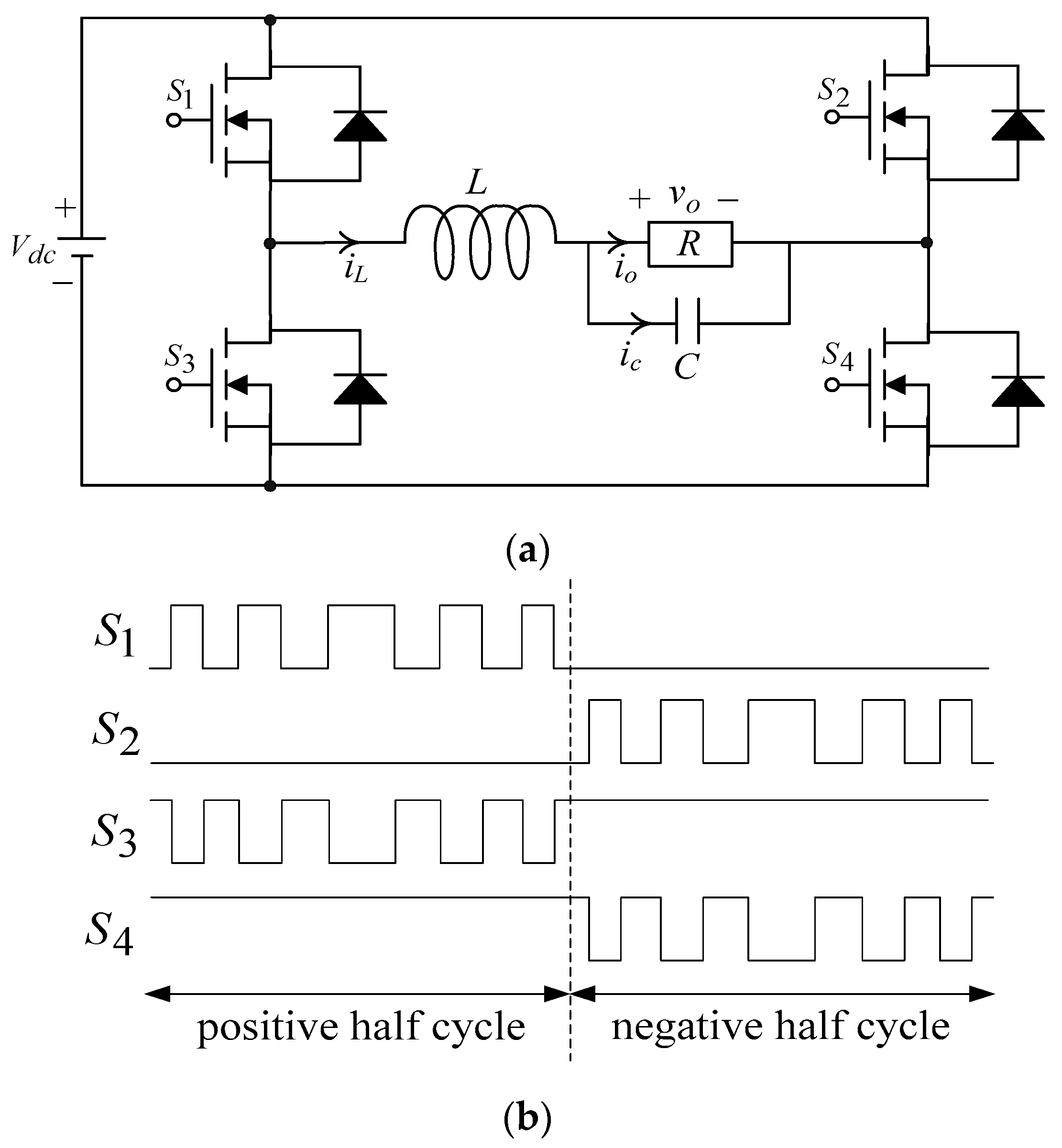
2. Modeling Description of Full-Bridge DC-AC Converter

Figure 1a depicts the full-bridge DC-AC converter, which is composed of three important units, namely the transistor switching elements, an inductor-capacitor low-pass filter, and a connected load; Figure 1b shows the gate control signals produced by the comparison of a reference sine waveshape and a high-frequency triangular carrier waveshape, which corresponds to DC-AC converter switches. Then, the DC bus voltage is defined as V d c , the R implies the resistive load, the output voltage, and current can be expressed as v o and i o , respectively. Analyzing the voltage and current in Figure 1a using Kirchhoff’s law and making the state variables x 1 = v o and x 2 = v ˙ o , then the state behavior of the full-bridge DC-AC converter can be expressed as:
{ x 1 = x ˙ 2 x ˙ 2 = 1 L C x 1 1 R C x 2 + 1 L C u ,
where the control signal u equals d · V d c , here d is duty ratio of switching limited amidst −1 and 1.
The design problem with the full-bridge DC-AC converter is a typical tracking control problem. Because the output voltage of the full-bridge DC-AC converter is a sinusoidal AC waveform, it must track the required reference AC waveform v r a c = 2 · V r m s · sin ( ω t ) , where V r m s denotes the root-mean-square value and ω is the angular frequency. Therefore, based on the relationship amidst (1) and v r a c , the error state variables can be defined as:
{ e 1 = x 1 v r a c   e 2 = x 2 v ˙ r a c .
Then, using the (1) and (2), the error state equation for the full-bridge DC-AC converter can be written as follows:
{ e ˙ 1 = x ˙ 1 v ˙ r a c   = e 2 e ˙ 2 = x ¨ 1 v ¨ r a c = x ˙ 2 v ¨ r a c = 1 L C e 1 1 R C e 2 + 1 L C u 1 L C v r a c 1 R C v ˙ r a c v ¨ r a c .
The error dynamics of the (3) reveals that the control signal u needs to be carefully and well designed. In this way, the system states e 1 and e 2 will quickly reach and converge to the equilibrium point within a limited period of time. It is worth noting that in the path tracking control design, once the NFCTA establishes a fast limited-time closed-loop convergence, the system response exhibits strong insensitivity and eternal stability. The NFCTA is used in the control of full-bridge DC-AC converters not only to allow faster dynamic response, but also to afford more precise control of the steady state. In actual implementation, there is the possibility of drastic changes in the internal parameters of the plant, severe interference from external loads, and highly nonlinear uncertainties, thereby leading to system trembling or great steady-state errors. The CPSO has been considered as a useful methodology to overcome the problems of trembling and steady-state errors in practical non-linear system applications. Based on chaotic mapping, the CPSO makes implementation easier and will not converge untimely, so the system can avoid falling into the dilemma of local optimization. With the smart combination of NFCTA and CPSO, the controller parameters of the NFCTA can be optimized globally and produce a full-bridge DC-AC converter with higher performance.

3. Proposed Control Strategy

For ease of analysis, the second-order uncertain nonlinear error state system of the (3) can be reformulated as:
{ e ˙ 1 = e 2 e ˙ 2 = f + w ˜ + b u v ¨ r a c ,
where f = 1 L C e 1 1 R C e 2 , b = 1 L C u , u connotes the control input, and w ˜ = 1 L C v r a c 1 R C v ˙ r a c implies the internal parameter changes of the plant, the disturbances of external load, and the uncertainties of nonlinearity. The w ˜ is expressed as the limitation of an inequality w ˜ ϕ , where ϕ is positive constant. Aiming at the error state Equation (3), the sliding surface of the NFCTA can be designed as follows to ensure faster convergence without singularities and to track the reference sine wave more accurately:
σ = e 1 + g | e 1 | m 1 s i g n ( e 1 ) + h | e 2 | m 2 s i g n ( e 2 ) ,
where g ,   h > 0 , m 1 > 1 , and s i g n ( · ) is approximated by tanh ( · ) . 1 < m 2 < 2 . The (5) implies that the state is insensitive to changes in system parameters and external loading interferences during sliding mode action (sliding phase). Nevertheless, when the state trajectory is forced towards the sliding surface (reaching phase), the fast limited-time convergence and robustness is not always guaranteed; Gao and Hung first proposed a new concept of sliding-mode reaching law to solve this dilemma [76], and many researchers have improved classic sliding-mode reaching law for various applications [77,78,79,80,81].
Based on the principle in the [76] and [77], we reconstruct a power reaching law-based sliding mode as follows:
σ ˙ = γ 1 | σ | p 1 s i g n ( σ ) γ 2 | σ | p 2 s i g n ( σ ) γ 3 | σ | p 3 σ ,
where γ 1 ,   γ 2 ,   γ 3 > 0 , 0 < p 1 < 1 , p 2 > 1 , p 3 > 0 , and s i g n ( · ) is approximated by tanh ( · ) .
After the mathematical operation from the (4) to (6), the resultant NFCTA control law u generates:
u ( t ) = b 1 [ f + ( | e 2 | 2 m 2 / h m 2 s i g n ( e 2 ) ) · ( 1 + g m 1 | e 1 | m 1 1 )                     + γ 3 | σ | p 3 σ + γ 1 | σ | p 1 s i g n ( σ ) + γ 2 | σ | p 2 s i g n ( σ ) + γ 3 | σ | p 3 σ + v ¨ r a c ] .
Theorem 1.
In case the (7) is applied to system dynamics (4) and the sliding surface σ as well as a power reaching law-based sliding mode (6) are employed, the system behavior will be satisfied with the fast convergence to equilibrium state within a limited time.
Proof. 
Suppose the following Lyapunov function candidate:
V = 0.5 × σ 2 .
The time derivative of V can be derived while following trajectory behavior (4) with control laws (7):
V ˙ = σ σ ˙ = σ ( e ˙ 1 + g m 1 | e 1 | m 1 1 s i g n ( e 1 ) e ˙ 1 + h m 2 | e 2 | m 2 1 s i g n ( e 2 ) e ˙ 2 ) h m 2 | e 2 | m 2 1 ( γ 1 | σ | p 1 + 1 s i g n ( σ ) + γ 2 | σ | p 2 + 1 s i g n ( σ ) + γ 3 | σ | p 3 + 2 ϕ | σ | ) .
□.
When implemented in a digital signal processor, the continue-time derivatives in the (4)–(9) can be approximated by Euler’s methodology: e ˙ e ( k + 1 ) e ( k ) / T , where T = t k + 1 t k (the sample interval in seconds), t k = k T (for a constant sample interval), k represents an integer, e ( k ) stands for the value of e at t k , and e ( k + 1 ) indicates the value of e at t k + 1 . Such approximation can be employed in place of all derivatives that appear in the NFCTA differential Equations (4)–(9) to yield corresponding discrete-time functions. Thereby, it can be known from (9) that σ and e 2 are not equal to zero, so V ˙ will be less than zero, which is consistent with Lyapunov’s stability theorem. The strong and insensitive SMC feedback system will converge to the equilibrium zone in a fast limited time. When an internal acutese plant parametric changes or external nonlinear load intermission is connected to the full-bridge DC-AC converter, it eternally induces high frequency trembling or steady-state errors, and may lead to inaccurate tracking trajectory in transient and steady-state conditions. As a result, the adjustment of SMC parameters exposes difficult decisions and time-consuming computations, causing the descent of system adaptability and the crisis of untimely convergence. The CPSO with population diversity and untimely convergence avoidance can really relieve the effects of tremor and steady-state errors. It can adaptively tune and determine strong NFCTA control parameters, therefore obtaining the global optimal solution and eluding untimely falling into the local extreme value. The tradition PSO utilized the (10) and (11) to indicate a model of particle evolution, which can then update the velocity and position of each particle as it flies towards its destination:
V ( t + 1 ) = Ω V ( t ) + ς 1 · r a n · ( X p b e s t ( t ) X ( t ) )   + ς 2 · r a m · ( X g b e s t X ( t ) ) ,
X ( t + 1 ) = X ( t ) + V ( t + 1 ) ,
where V ( t + 1 ) represents present flying speed, X ( t ) indicates present position, X p b e s t shows individual best position, X g b e s t stands for global best position, ς 1 and ς 2 signify learning factor, ran and ram are random number amidst 0 and 1, and Ω = Ω max Γ · [ ( Ω max Ω min ) / Γ max ] denote inertia weight, here the Γ denotes the present generations number and Γ max symbols total number of generations. While the velocity of certain particle approaches zero, other particles conducted by X p b e s t and X g b e s t rapidly enter the zone near the stagnant particles’ location. Due to the stochastic nature of particles during initialization and evolution, updates are seemingly purposeless. Once X g b e s t falls into a local extreme, then the entire swarm will show precocious convergence, reducing search performance. Owing to the non-repeatability of chaos, the CPSO can explore according to probability at a higher speed than random and traversal investigations.
Therefore, a typical Logistic mapping adopted for chaos can be defined as:
χ ( t + 1 ) = β · χ ( k ) · ( 1 χ ( t ) ) ,
where the symbol β represents the control coefficient, which is usually set to 4 [58,59,60]. The speed update equation of the CPSO can be expressed as:
V ( t + 1 ) = Ω V ( t ) + ς 1 · χ · ( X p b e s t ( t ) X ( t ) )   + ς 2 · χ · ( X g b e s t X ( t ) ) ,
where χ is a function based on the result of logistic mapping, and its value is amidst 0 and 1 [58,59,60]. Since this algorithm can achieve the ability to escape from the best solution in the local region, there is not much randomness and therefore, the solution changes within the present solution range. The χ ( t ) can be set to be generated randomly amidst 0 and 0.1, thus allowing the particles to escape from the extreme value of the local region without too much randomness and difficulty in convergence. The process of the algorithm is represented in the following, and its Matlab code can refer to the literature [82]. Step 1: The initialization of position, velocity, and inertia weight is executed by the chaotic operation. The best individual position X p b e s t as well as the best global position X g b e s t are computed. An integrated absolute error ( IAE = 0 | e 1 ( τ ) | d τ ) is use as the objective function. Step 2: According to the (10) and (11), the particle’s velocity and position can be updated. Step 3: Compute the adaptive value, and in case it is better than the adaptive value of X p b e s t , the present position with the X p b e s t is renewed; if it is preferable to the adaptive value of X g b e s t , renovate the present position with the X p b e s t . Step 4: Determine whether the termination condition is satisfactory or not. If the answer is yes, perform step 7 forthright, otherwise fulfill step 5. Step 5: Determine whether the algorithm is sluggish or not. If the answer is yes, accomplish step 6 immediately, otherwise carry out Step 2 and Step3. Step 6: Depending on the difference surrounded by the adaptive value of the particles, regulate the position of the particles to perform Step 2 and Step3. Step 7: Output relative information with the X g b e s t and then stop this algorithm. The comparison between CPSO and different optimization algorithms for searching steps in objective space is shown in Figure 2.
Additionally, three commonly used optimization algorithms, such as genetic algorithm (GA), differential evolution (DE), and simulated annealing (SA) can be compared and analyzed [60,61,62,63,64,65]. For the genetic algorithm (GA), the solution is graded through the adaptation value. The parental choices are based on probability and are more appropriate for the individual. The crossover operation generates a descendant, which is taken from the parent, and the solution may be similar to the parent. The GA has a tendency to generate solutions that may be aggregated around some good solutions in the aggregate. The diversity of GA is entered into the solution by introducing different mutation operations, and its solution time will increase non-linearly with the augmentation of the population. The generation mechanism of DE new solution is similar to that of traditional PSO, and its population search ability is about the same as that of traditional PSO. The diversity is preferable because the best solution in the population has no effect on other solutions, but the mutation vector is usually a solution that comes from the non-primitive population. The number of iterations in the traditional PSO is less, and the performance of traditional PSO far exceeds that of SA. The SA requires a particularly large number of iterations to achieve the same results as traditional PSO, however the time of each iteration in the traditional PSO is much longer than that of SA.

4. Simulation and Experimental Results

The commercial optimization software, for example HEEDS-MDO, can be used to design the optimization of engineering problems. However, based on the current funding considerations and the currently available software resources, the MATLAB/Simulink is used to simulate the full-bridge DC-AC converter controlled by the proposed strategy and a typical TA. Figure 3 displays the simulated block diagram of the full-bridge DC-AC converter with the control strategy. Likewise, the circuitry of the proposed full-bridge DC-AC converter has been implemented using a dSPACE DS1102 controller board (dSPACE GmbH, Paderborn, Germany) based on a Texas Instruments digital signal processor, substantiating the applicability of the proposed strategy. The photo of the experimental setup is displayed in Figure 4. The system parameters of the full-bridge DC-AC converter are listed in Table 1. It should be noted that the component values can be selected as proposed in [83,84,85] below. (i) Pick the switching frequency [84,85]: In order to reduce the size of the filter, it is necessary to elect a sufficiently high switching frequency, and in the case of metal-oxide-semiconductor field-effect transistor switches, it is often elected amidst 20 and 40 kHz. (ii) Pick a coefficient related to the cutoff frequency of the LC filter [83]: When the factor is small, the switching frequency and the fundamental frequency have large attenuation and small amplification, respectively. The minimum value of the factor can be calculated, and the modulation value is preferably 0.95 or less. (iii) Pick a factor related to both switching frequency and inductance ripple current [83]: The ripple current of the inductance is preferably in the range of 20% to 40%. Then, both L and C component values are calculated from the picked coefficients of (8), (20), (25), and (26) of [83].
The simulated output-waveshapes of the full-bridge DC-AC converters shown in Figure 5 and Figure 6 are respectively divided into the proposed strategy and the typical TA under TRIAC (triode for alternating current)-controlled loads (at 90/270 firing angles, changing from no load to full load of 12 ohm). The proposed strategy displays a smaller voltage dip and speedier recovery time than the typical TA. For the sake of examining the performance of the full-bridge DC-AC converter at highly non-linear load situations, Figure 7 depicts the simulated output-waveshape of the full-bridge DC-AC converter at a rectified load ( C d = 200   μ F and R d = 30 ohm) using the proposed strategy. The output-voltage has a good sine form, and its voltage % THD can reach 0.14%, which is less than 5% of the IEEE standard. Figure 8 represents a typical TA subject to the situation of a rectified load ( C d = 200   μ F and R d = 30 ohm), the simulated output-waveshape of the full-bridge DC-AC converter exposures of an unsatisfactory contortion and a quite high voltage %THD of 13.57% yields. Thereby, the proposed strategy completely enhances the steady-state performance of the full-bridge DC-AC converter, even under severe non-linear loading. Table 2 gives the simulated output-voltage dip and %THD for TRIAC-controlled loads and rectified loads, respectively. Based on the above response under different load conditions, we can further understand that the output LC filter tends to cause current stress in the full-bridge DC-AC converter under transient conditions, and the load current may also increase current stress. When there is a high inductive load, the design of the filter ratio has been proposed in the (20) of the literature [84], and it is suggested that the middle range between the upper and lower boundaries can be used for inductive loads. In addition, if the converter is connected to an inductive load, the power factor and efficiency of the output sine voltage are unsatisfactory. Earlier works have shown the behavioral response of the full-bridge DC-AC converter to inductive loads and have also revealed that power factor and efficiency can be improved by using a capacitor [86]. Figure 9 and Figure 10 show the experimental output-waveshapes of the full-bridge DC-AC converter controlled by the proposed strategy and the typical TA under resistive full-load conditions, respectively. The output voltage is both distortion-free and presents a beautiful sine wave; this means that under the condition of pure resistance linear load, the full-bridge DC-AC converter is difficult to be affected by its interference. Figure 11 illustrates the experimental output-waveshape of the full-bridge DC-AC converter under the proposed strategy with a step change in load (trigger angle of 90, changing from no load to 12 ohm at full load). In line with the simulation result, a small immediate voltage drop appears and then quickly returns to the reference voltage level. Figure 12 exhibits the experimental output-waveshape of a typical TA-controlled full-bridge DC-AC converter with a step change in load (90 trigger angle from no load to full load of 12 ohm). This tells us that the descent of the controller’s compensation capability is due to bad transient tracking response, large voltage dip, and slow retrieval time. Figure 13 and Figure 14 reveal the experimental output-waveshapes of the full-bridge DC-AC converters with the proposed strategy as well as a typical TA in the presence of LC parameter variations, where the output-voltage of the proposed full-bridge DC-AC converter (output voltage of 0.08% THD) is closer to a sinusoidal waveshape and less prone to deformation than a typical TA full-bridge DC-AC converter (output voltage of 12.91% THD). From the comparison amidst the proposed strategy and a typical TA, the proposed full-bridge DC-AC converter has better transience and steady-state tracking behavior than the typical TA-controlled full-bridge DC-AC converter under various load tests. Table 3 provides the experimental output-voltage dip and %THD under step-load changes and LC variations.

5. Conclusions

In this paper, a CPSO-optimized NFCTA strategy is proposed and then applied to a full-bridge DC-AC converter that can provide low THD and fast dynamic tracking response. The NFCTA has the ability to quickly converge to the equilibrium region within a limited time, and also infers the absence of singularities. Because system uncertainties may be overestimated or underestimated, there are still concerns about trembling and steady-state errors surrounding the sliding surface of the NFCTA. The immoderate conservativeness of the NFCTA design can be mitigated by using the CPSO to estimate the upper limits of the plant’s internal parameter changes and external load intermission. If such an immoderately cautious sliding-mode switching amplitude value is therefore lessened, there will be no tremor generated by the NFCTA, which greatly achieves the advancement of the full-bridge DC-AC converter dynamics and steady state behaviors. The proposed strategy adopts Lyapunov’s theorem to interpret and authenticate the stability of the feedback system, the attainability of the sliding-mode manifold within a limited-time area and the quick convergence of trajectory tracking. Numerical simulation results and the experimental results of the prototype full-bridge DC-AC converter point to the efficacy of the proposed strategy. In future research, the full-bridge DC-AC converter can be connected to the network, but the DC-AC converter and the grid must be synchronized. In other words, both of them must have the same amplitude, frequency, and phase angle; in order to achieve this requirement, a simple phase locked loop (PLL) structure is usually considered.

Author Contributions

E.-C.C., conceived and investigated the algorithm, designed the circuit, and developed the methodology; C.-A.C. and R.-C.W., prepared software resources, set up simulation software; E.-C.C., performed control system simulations; E.-C.C., carried out experiments, analyzed the results, wrote the paper and revised it for submission. All authors have read and agreed to the published version of the manuscript.

Funding

This research was funded by the 2021 ISU Research Project, under contract number ISU-110-01-02A. This research was also funded by the Ministry of Science and Technology (MOST) of Taiwan, under contract numbers MOST 109-3116-F-006-020-CC1 and MOST 107-2221-E-214-006.

Acknowledgments

The authors would like to thank the 2021 ISU Research Project (ISU-110-01-02A) and the research projects (MOST 109-3116-F-006-020-CC1 and MOST 107-2221-E-214-006) of Ministry of Science and Technology (MOST), Taiwan for their support of experimental materials and equipment.

Conflicts of Interest

The authors declare no conflict of interest.

References

  1. Batarseh, I.; Harb, A. Power Electronics: Circuit Analysis and Design; Springer International Publishing: Cham, Switzerland, 2018. [Google Scholar]
  2. Sozański, K. Digital Signal Processing in Power Electronics Control Circuits; Springer International Publishing: London, UK, 2017. [Google Scholar]
  3. Simões, M.G.; Farret, F.A. Modeling Power Electronics and Interfacing Energy Conversion Systems; John Wiley & Sons: Hoboken, NJ, USA; IEEE Press: Piscataway, NJ, USA, 2017. [Google Scholar]
  4. Abad, G. Power Electronics and Electric Drives for Traction Applications; John Wiley & Sons: Chichester, UK, 2017. [Google Scholar]
  5. Ramos, G.A.; Ruget, R.I.; Costa-Castelló, R. Robust Repetitive Control of Power Inverters for Standalone Operation in DG Systems. IEEE Trans. Energy Convers. 2020, 35, 237–247. [Google Scholar] [CrossRef]
  6. Li, J.; Wen, B.Y.; Wang, H.Y. Adaptive Virtual Inertia Control Strategy of VSG for Micro-Grid Based on Improved Bang-Bang Control Strategy. IEEE Access 2019, 7, 39509–39514. [Google Scholar] [CrossRef]
  7. Singh, S.K.; Choudhuri, S.G. Hybrid iterative learning control strategy for single-phase UPS inverter using inductor current active damping. J. Eng. 2018, 2018, 230–238. [Google Scholar] [CrossRef]
  8. Hammoudi, M.Y.; Saadi, R.; Cardoso, A.J.M.; Benbouzid, M.E.H.; Sahraoui, M. Practical implementation of H-infinity control for fuel cell-interleaved boost converter. Int. J. Model. Simul. 2018, 1, 44–61. [Google Scholar] [CrossRef]
  9. Alharbi, B.; Alhomim, M.; McCann, R. Robust Control of DC-DC Boost Converter by using µ-Synthesis Approach. IFAC Pap. 2019, 52, 200–205. [Google Scholar] [CrossRef]
  10. Orosz, T.; Rassõlkin, A.; Kallaste, A.; Arsénio, P.; Pánek, D.; Kaska, J.; Karban, P. Robust Design Optimization and Emerging Technologies for Electrical Machines: Challenges and Open Problems. Appl. Sci. 2020, 10, 6653. [Google Scholar] [CrossRef]
  11. Taguchi, G.; Phadke, M.S. Quality engineering through design optimization. In Quality Control, Robust Design, and the Taguchi Method; Springer: Boston, MA, USA, 1989; pp. 77–96. [Google Scholar]
  12. Souza, G.F.M.; Melo, I.S.; Michalski, M.A.C. Applying Mahalanobis-Taguchi method to detect faults in rotating machinery. In Safety and Reliability–Safe Societies in a Changing World; Taylor & Francis Group: London, UK, 2018; pp. 1115–1123. [Google Scholar]
  13. Suh, N.P. Axiomatic Design Theory for Systems. Res. Eng. Des. 1998, 10, 189–209. [Google Scholar] [CrossRef]
  14. Garraoui, R.; Hamed, M.B.; Sbita, L. A robust optimization technique based on first order sliding mode approach for photovoltaic power systems. Int. J. Autom. Comput. 2015, 12, 620–629. [Google Scholar] [CrossRef] [Green Version]
  15. Lei, G.; Zhu, J.; Guo, Y.; Liu, C.; Ma, B. A Review of Design Optimization Methods for Electrical Machines. Energies 2017, 10, 1962. [Google Scholar] [CrossRef] [Green Version]
  16. Xiao, S.; Li, Y.L.; Rotaru, M.H.; Sykulski, J.K. Six Sigma Quality Approach to Robust Optimization. IEEE Trans. Magn. 2015, 51, 1–4. [Google Scholar] [CrossRef] [Green Version]
  17. Wang, B.F.; Zhang, X.N.; Manandhar, U.; Gooi, H.B.; Liu, Y.T.; Tan, X.J. Bidirectional Three-Level Cascaded Converter With Deadbeat Control for HESS in Solar-Assisted Electric Vehicles. IEEE Trans. Transp. Electrif. 2019, 5, 1190–1201. [Google Scholar] [CrossRef]
  18. Lu, N.J.; Hredzak, B. Current Ripple Reduction for Photovoltaic Powered Single-Phase Buck-Boost Differential Inverter under Nonlinear Loads. In Proceedings of the 2018 7th International Conference on Renewable Energy Research and Applications (ICRERA), Paris, France, 14–17 October 2018; pp. 544–548. [Google Scholar]
  19. Wang, D.N.; Meng, F.W.; Meng, S.G.; Pang, A.P. Design of Stable Controller for Flexible Solar Panel by H Loop-Shaping Method. Complexity 2020, 2020, 1–8. [Google Scholar] [CrossRef]
  20. Pradhan, S.S.; Pradhan, R.; Subudhi, B. Design and Analysis of an H∞ Controller for a Single Phase Grid Connected Photovoltaic System with Parametric Uncertainties. In Proceedings of the 2019 Second International Conference on Advanced Computational and Communication Paradigms (ICACCP), Gangtok, India, 25–28 February 2019; pp. 1–6. [Google Scholar]
  21. Derbel, N.; Ghommam, J.; Zhu, Q. Applications of Sliding Mode Control; Springer International Publishing: Singapore, 2017. [Google Scholar]
  22. Mehta, A.; Naik, B. Sliding Mode Controllers for Power Electronic Converters; Springer International Publishing: Singapore, 2019. [Google Scholar]
  23. Vardan, M.; Ekaterina, A. Sliding Mode in Intellectual Control and Communication: Emerging Research and Opportunities; IGI Global: Hershey, PA, USA, 2017. [Google Scholar]
  24. Sira-Ramirez, H. Sliding Regimes in General Non-Linear Systems: A Relative Degree Approach. Int. J. Control 1989, 50, 1487–1506. [Google Scholar] [CrossRef]
  25. Utkin, V.I. Variable Structure Systems with Sliding Modes. IEEE Trans. Autom. Control 1977, AC-22, 212–222. [Google Scholar] [CrossRef]
  26. Dekka, G.; Gudey, S.K. Robust Controllers for a Single-Stage Boost DC-AC Inverter. In Proceedings of the 2020 IEEE 9th Power India International Conference (PIICON), Sonepat, India, 28 February–1 March 2020; pp. 1–6. [Google Scholar]
  27. Repecho, V.; Biel, D.; Olm, J.M. A simple switching frequency regulated sliding mode controller for a VSI with a full digital implementation. IEEE J. Emerg. Sel. Top. Power Electron. 2020. [CrossRef]
  28. Wang, Y.; Wai, R.J. Design of Discrete-Time Backstepping Sliding- Mode Control for LCL-Type Grid-Connected Inverter. IEEE Access 2020, 8, 95082–95098. [Google Scholar] [CrossRef]
  29. Katir, H.; Abouloifa, A.; Noussi, K.; Lachkar, I. Sliding Mode Based Control of Five Cascaded H-Bridge Inverters. In Proceedings of the 2020 International Conference on Electrical and Information Technologies (ICEIT), Rabat, Morocco, 4–7 March 2020; pp. 1–6. [Google Scholar]
  30. Rafaq, M.S.; Mohammed, S.A.Q.; Choi, H.H.; Jung, J.W. An Improved Sliding Mode Control Technique to Mitigate Mismatched Parameter Uncertainties of Three-Phase Voltage Source Inverters. IEEE Access 2020, 8, 81932–81942. [Google Scholar] [CrossRef]
  31. Guo, L.P.; Hung, J.Y.; Nelms, R.M. Digital Implementation of Sliding Mode Fuzzy Controllers for Boost Converters. In Proceedings of the Twenty-First Annual IEEE Applied Power Electronics Conference and Exposition (APEC), Dallas, TX, USA, 19–23 March 2006; pp. 1424–1429. [Google Scholar]
  32. Gomariz, S.; Alarcon, E.; Guinjoan, F.; Vidal-ldiarte, E.; Martinez-Salamero, L. Piecewise PWM-sliding global control of a boost switching regulator by means of first-order Takagi-Sugeno fuzzy control. In Proceedings of the 2001 IEEE International Symposium on Circuits and Systems (ISCAS), Sydney, NSW, Australia, 6–9 May 2001; pp. 715–718. [Google Scholar]
  33. Medhaffar, H.; Derbel, N. Fuzzy Second-Order Sliding Mode Control Design for a Two-Cell DC-DC Converter. Math. Probl. Eng. 2020, 2020, 1–9. [Google Scholar] [CrossRef]
  34. Shi, Y.; Sen, P.C. Application of variable structure fuzzy logic controller for DC-DC converters. In Proceedings of the 27th Annual Conference of the IEEE Industrial Electronics Society (IECON), Denver, CO, USA, 29 November–2 December 2001; pp. 2026–2031. [Google Scholar]
  35. Laraki, M.H.; Brahmi, B.; Chandra, A.; Agbossou, K.; Cardenasgonzalez, A. A Novel Adaptive Control of Three-Phase Inverter for Standalone Distributed Generation System Using Modified Super-Twisting Algorithm with Time Delay Estimation. In Proceedings of the 2019 IEEE 28th International Symposium on Industrial Electronics (ISIE), Vancouver, BC, Canada, 12–14 June 2019; pp. 740–745. [Google Scholar]
  36. Zhao, Z.H.; Yang, J.; Li, S.H.; Yu, X.H.; Wang, Z. Continuous Output Feedback TSM Control for Uncertain Systems With a DC–AC Inverter Example. IEEE Trans. Circuits Syst. II Express Briefs 2018, 65, 71–75. [Google Scholar] [CrossRef]
  37. Habib, H.U.R.; Wang, S.R.; Elmorshedy, M.F.; Waqar, A. Performance Analysis of Combined Model-Predictive and Slide-Mode Control for Power Converters in Renewable Energy Systems. In Proceedings of the 2019 22nd International Conference on Electrical Machines and Systems (ICEMS), Harbin, China, 11–14 August 2019; pp. 1–5. [Google Scholar]
  38. Wen, J.; Nie, Q.B.; Wang, Y.M.; Xu, Q.Y.; Feng, Y. Non-Singular Terminal Sliding Mode Control of Inverter-Fed PMSM System with Chattering Elimination. In Proceedings of the 2018 IEEE 8th Annual International Conference on CYBER Technology in Automation, Control, and Intelligent Systems (CYBER), Tianjin, China, 19–23 July 2018; pp. 1370–1375. [Google Scholar]
  39. Levaggi, L. High-gain feedback and sliding modes in infinite dimensional systems. Control Cybern. 2004, 33, 33–50. [Google Scholar]
  40. Marino, R. High-gain feedback in non-linear control systems. Int. J. Control 2007, 42, 1369–1385. [Google Scholar] [CrossRef]
  41. Yang, H.T.; Zhang, Y.C.; Huang, P. Improved Predictive Current Control of IM Drives Based on a Sliding Mode Observer. In Proceedings of the 2019 IEEE International Symposium on Predictive Control of Electrical Drives and Power Electronics (PRECEDE), Quanzhou, China, 31 May–2 June 2019; pp. 1–6. [Google Scholar]
  42. Yang, B.; Yu, T.; Shu, H.C.; Yao, W.; Jiang, L. Sliding-mode perturbation observer-based sliding-mode control design for stability enhancement of multi-machine power systems. Trans. Inst. Meas. Control 2018, 41, 1418–1434. [Google Scholar] [CrossRef]
  43. Chaturvedi, S.; Fulwani, D.; Guerrero, J.M. Adaptive-Sliding-Mode-Control based Output Impedance Shaping for Ripple Management in DC Microgrids Affected by Inverter Loads. IEEE Trans. Sustain. Energy 2020. [CrossRef]
  44. Esmaeili, H.; Asadi, M. A Sliding Mode Controller Based on Robust Model Reference Adaptive Proportional-Integral Control for Stand-Alone Three-Phase Inverter. J. Mod. Power Syst. Clean Energy 2020, 65, 1–11. [Google Scholar]
  45. Roy, T.K.; Mahmud, M.A.; Islam, S.N.; Rajasekar, N.; Muttaqi, K.M.; Oo, A.M.T. Robust Adaptive Direct Power Control of Grid-Connected Photovoltaic Systems. In Proceedings of the 2020 IEEE International Conference on Power Electronics, Smart Grid and Renewable Energy (PESGRE2020), Cochin, India, 2–4 January 2020; pp. 1–6. [Google Scholar]
  46. Davari, M.; Aghababa, M.P.; Blaabjerg, F.; Saif, M. A Modular Adaptive Robust Nonlinear Control for Resilient Integration of VSIs into Emerging Modernized Microgrids. IEEE J. Emerg. Sel. Top. Power Electron. 2020. [CrossRef]
  47. Bag, A.; Subudhi, B.; Ray, P.K. An Adaptive Variable Leaky Least Mean Square Control Scheme for Grid Integration of a PV System. IEEE Trans. Sustain. Energy 2020, 11, 1508–1515. [Google Scholar] [CrossRef]
  48. Kumar, N.; Saha, T.K.; Dey, J. Control of Dual Inverter Based PV System through Double-Band Adaptive SMC. In Proceedings of the 2019 IEEE International Conference on Sustainable Energy Technologies and Systems (ICSETS), Bhubaneswar, India, 26 February–1 March 2019; pp. 156–160. [Google Scholar]
  49. Gautam, A.R.; Fulwani, D. Adaptive SMC for the Second-Order Harmonic Ripple Mitigation: A Solution for the Micro-Inverter Applications. IEEE Trans. Power Electron 2019, 34, 8254–8264. [Google Scholar] [CrossRef]
  50. Bag, A.; Subudhi, B.; Ray, P.K. An adaptive sliding mode control scheme for grid integration of a PV system. CPSS Trans. Power Electron. Appl. 2018, 3, 362–371. [Google Scholar] [CrossRef]
  51. Wang, N.; Yu, H.S.; Liu, X.D. DTC of induction motor based on adaptive sliding mode control. In Proceedings of the 2018 Chinese Control and Decision Conference (CCDC), Shenyang, China, 9–11 June 2018; pp. 4030–4034. [Google Scholar]
  52. Kermadi, M.; Salam, Z.; Berkouk, E.M. An adaptive sliding mode control technique applied in grid-connected PV system with reduced chattering effect. In Proceedings of the 2017 IEEE Conference on Energy Conversion (CENCON), Kuala Lumpur, Malaysia, 30–31 October 2017; pp. 180–185. [Google Scholar]
  53. Deng, L.H.; Fei, J.T.; Cai, C.C. The photovoltaic systems based on a sliding mode and adaptive controller. In Proceedings of the 2016 35th Chinese Control Conference (CCC), Chengdu, China, 27–29 July 2016; pp. 8777–8782. [Google Scholar]
  54. Ishaque, K.; Salam, Z. A Deterministic Particle Swarm Optimization Maximum Power Point Tracker for Photovoltaic System under Partial Shading Condition. IEEE Trans. Ind. Electron. 2013, 60, 3195–3206. [Google Scholar] [CrossRef]
  55. Parsopoulos, K.E.; Vrahatis, M.N. Particle Swarm Optimization and Intelligence: Advances and Applications; Information Science Reference: Hershey, PA, USA, 2010. [Google Scholar]
  56. Ruiz-Cruz, R.; Sanchez, E.N.; Ornelas-Tellez, F.; Loukianov, A.G.; Harley, R.G. Particle Swarm Optimization for Discrete-Time Inverse Optimal Control of a Doubly Fed Induction Generator. IEEE Trans. Cybern. 2013, 43, 1698–1709. [Google Scholar] [CrossRef]
  57. Zhao, J.H.; Wen, F.S.; Dong, Z.Y.; Xue, Y.S.; Wong, K.P. Optimal Dispatch of Electric Vehicles and Wind Power Using Enhanced Particle Swarm Optimization. IEEE Trans. Ind. Inform. 2012, 8, 889–899. [Google Scholar] [CrossRef]
  58. Tang, Y.F.; Ju, P.; He, H.B.; Qin, C.; Wu, F. Optimized Control of DFIG-Based Wind Generation Using Sensitivity Analysis and Particle Swarm Optimization. IEEE Trans. Smart Grid 2013, 4, 509–520. [Google Scholar] [CrossRef]
  59. Wang, J.D.; Yang, F. Optimal capacity allocation of standalone wind/solar/battery hybrid power system based on improved particle swarm optimisation algorithm. IET Proc. Renew. Power Gener. 2013, 7, 443–448. [Google Scholar] [CrossRef]
  60. Ali, M.; Iqbal, A.; Anees, M.A.; Khan, M.R.; Rahman, K.; Ayyub, M. Differential evolution-based pulse-width modulation technique for multiphase MC. IET Power Electron. 2019, 12, 2224–2235. [Google Scholar] [CrossRef]
  61. Liu, Z.Q.; Wu, H.B.; Jin, W.; Xu, B.; Ji, Y.; Wu, M. Two-step method for identifying photovoltaic grid-connected inverter controller parameters based on the adaptive differential evolution algorithm. IET Gener. Transm. Distrib. 2017, 11, 4282–4290. [Google Scholar] [CrossRef]
  62. Koch, G.G.; Osório, C.R.D.; Pinheiro, H.; Oliveira, R.C.L.F.; Montagner, V.F. Design Procedure Combining Linear Matrix Inequalities and Genetic Algorithm for Robust Control of Grid-Connected Converters. IEEE Trans. Ind. Appl. 2020, 56, 1896–1906. [Google Scholar] [CrossRef]
  63. Wang, Z.B.; Chinthavali, M.; Campbell, S.L.; Wu, T.; Ozpineci, B. A 50-kW Air-Cooled SiC Inverter With 3-D Printing Enabled Power Module Packaging Structure and Genetic Algorithm Optimized Heatsinks. IEEE Trans. Ind. Appl. 2019, 55, 6256–6265. [Google Scholar] [CrossRef]
  64. Lin, Z.Z.; Wang, J.H.; Fang, Z.J.; Hu, M.L.; Cai, C.S.; Zhang, J.K. Accurate Maximum Power Tracking of Wireless Power Transfer System Based on Simulated Annealing Algorithm. IEEE Access 2018, 6, 60881–60890. [Google Scholar] [CrossRef]
  65. Trovão, J.P.F.; Santos, V.D.N.; Pereirinha, P.G.; Jorge, H.M.; Antunes, C.H. A Simulated Annealing Approach for Optimal Power Source Management in a Small EV. IEEE Trans. Sustain. Energy 2013, 4, 867–876. [Google Scholar] [CrossRef]
  66. Chu, K.C.; Horng, D.J.; Chang, K.C. Numerical Optimization of the Energy Consumption for Wireless Sensor Networks Based on an Improved Ant Colony Algorithm. IEEE Access 2019, 7, 105562–105571. [Google Scholar] [CrossRef]
  67. Yang, S.B.; Wu, M.L.; Yao, X.; Jiang, J.C. Load Modeling and Identification Based on Ant Colony Algorithms for EV Charging Stations. IEEE Trans. Power Syst. 2015, 30, 1997–2003. [Google Scholar] [CrossRef]
  68. Yue, Y.G.; Cao, L.; Hu, J.; Cai, S.T.; Hang, B.; Wu, H. A Novel Hybrid Location Algorithm Based on Chaotic Particle Swarm Optimization for Mobile Position Estimation. IEEE Access 2019, 7, 58541–58552. [Google Scholar] [CrossRef]
  69. Pluhacek, M.; Senkerik, R.; Viktorin, A.; Kadavy, T.; Zelinka, I. Chaos Driven PSO with Attractive Search Space Border Points. In Proceedings of the 2018 IEEE Congress on Evolutionary Computation (CEC), Rio de Janeiro, Brazil, 8–13 July 2018; pp. 1–6. [Google Scholar]
  70. Cao, B.; Bo, M.M.; Pan, J.B.; Liu, Y. Static Voltage Stability Analysis Based on the Combination of Dynamic Continuous Power Flow and Adaptive Chaotic Particle Swarm Optimization. In Proceedings of the 2018 IEEE 3rd Advanced Information Technology, Electronic and Automation Control Conference (IAEAC), Chongqing, China, 12–14 October 2018; pp. 2217–2221. [Google Scholar]
  71. Hu, Q.Q.; Liu, H.Z.; Niu, C.S.; Du, M.Y.; Zhang, Y.A.; Ge, Y. The research and application of chaotic particle swarm optimization algorithm. In Proceedings of the 2017 13th International Conference on Natural Computation, Fuzzy Systems and Knowledge Discovery (ICNC-FSKD), Guilin, China, 29–31 July 2017; pp. 1058–1062. [Google Scholar]
  72. Li, N.; Shan, X.W.; Heng, L.; Ren, Y.P.; Pan, H.W.; Ge, L.J. Optimization of Micro-grid Dispatching Based on Adaptive Chaos Particle Swarm Optimization. In Proceedings of the 2019 IEEE Innovative Smart Grid Technologies–Asia (ISGT Asia), Chengdu, China, 21–24 May 2019; pp. 2445–2449. [Google Scholar]
  73. Vasant, P.M. Handbook of Research on Novel Soft Computing Intelligent Algorithms: Theory and Practical Applications; IGI Global: Hershey, PA, USA, 2013. [Google Scholar]
  74. Hosseinzadeh, M.; Salmasi, F.R. Power management of an isolated hybrid AC/DC micro-grid with fuzzy control of battery banks. IET Renew. Power Gener. 2015, 9, 484–493. [Google Scholar] [CrossRef]
  75. Valenciaga, F.; Puleston, P.F.; Battaiotto, P.E. Power control of a photovoltaic array in a hybrid electric generation system using sliding mode techniques. IEEE Proc. Control Theory Appl. 2001, 148, 448–455. [Google Scholar] [CrossRef]
  76. Gao, W.; Hung, J.C. Variable structure control of nonlinear systems. A new approach. IEEE Trans. Ind. Electron. 1993, 40, 45–55. [Google Scholar]
  77. Wang, Z.P.; Mao, Y.S.; Hu, Z.H.; Xie, Y.X. A Sliding Mode Control Design based on the Reaching Law for Matrix Rectifiers. J. Power Electron. 2016, 18, 1122–1130. [Google Scholar] [CrossRef] [Green Version]
  78. Chen, S.Y.; Liu, W.; Huang, H.X. Nonsingular Fast Terminal Sliding Mode Tracking Control for a Class of Uncertain Nonlinear Systems. J. Control Sci. Eng. 2019, 2019, 1–17. [Google Scholar] [CrossRef]
  79. Wang, T.H.; Zhao, M.Y.; Li, Y.C.; Liu, K.P. Double-power reaching law sliding mode control for spacecraft decline based on radial basis function networks. In Proceedings of the 2017 29th Chinese Control and Decision Conference (CCDC), Chongqing, China, 28–30 May 2017; pp. 5396–5401. [Google Scholar]
  80. Liu, K.; Cao, Y.; Wang, S.; Li, Y. Terminal sliding mode control for landing on asteroids based on double power reaching law. In Proceedings of the 2015 IEEE International Conference on Information and Automation, Lijiang, China, 8–10 August 2015; pp. 2444–2449. [Google Scholar]
  81. Wang, H.; Zhao, X.; Tian, Y. Trajectory tracking control of XY table using sliding mode adaptive control based on fast double power reaching law. Asian J. Control 2016, 18, 2263–2271. [Google Scholar] [CrossRef]
  82. Khare, V.; Nema, S.; Baredar, P. Ocean Energy Modeling and Simulation with Big Data: Computational Intelligence for System Optimization and Grid Integration; Butterworth-Heinemann Elsevier Ltd.: Oxford, UK, 2020; Chapter 8. [Google Scholar]
  83. Ahmad, A.A.; Abrishamifar, A.; Farzi, M. A New Design Procedure for Output LC Filter of Single Phase Inverters. In Proceedings of the 2010 Power Electronics and Intelligent Transportation System (PEITS), Shenzhen, China, 13–14 November 2010; pp. 86–91. [Google Scholar]
  84. Dahono, P.A.; Purwadi, A. An LC filter Design Method for Single-Phase PWM Inverters. In Proceedings of the 1995 Power Electronics and Drive Systems, Singapore, 21–24 February 1995; pp. 571–576. [Google Scholar]
  85. Kim, H.S.; Sul, S.K. A Novel Filter Design for Output LC Filters of PWM Inverters. J. Power Electron. 2011, 11, 74–81. [Google Scholar] [CrossRef] [Green Version]
  86. Williams, B.W. Power Electronics: Devices, Drivers, Applications, and Passive Components; McGraw-Hill: New York, NY, USA, 1992. [Google Scholar]
Figure 1. Common full-bridge DC-AC converter structure (a) Circuit diagram. (b) Switching pulse pattern.
Applsci 11 01211 g001
Figure 2. Comparison between chaos particle swarm optimization (CPSO) and different optimization algorithms for searching steps.
Applsci 11 01211 g002
Figure 3. Simulated block diagram of full-bridge DC-AC converter with the control strategy.
Applsci 11 01211 g003
Figure 4. Photo of the experimental setup.
Applsci 11 01211 g004
Figure 5. Simulated output voltage and current with the proposed strategy under TRIAC (triode for alternating current)-controlled load (vertical: 50 V/division and 15 A/division).
Applsci 11 01211 g005
Figure 6. Simulated output voltage and current with the typical TA (terminal attractor) under TRIAC-controlled load (vertical: 50 V/division and 15 A/division).
Applsci 11 01211 g006
Figure 7. Simulated output voltage and current with the proposed strategy under rectified load (vertical: 50 V/division and 25 A/division).
Applsci 11 01211 g007
Figure 8. Simulated output voltage and current with the typical TA under rectified load (vertical: 50 V/division and 25 A/division).
Applsci 11 01211 g008
Figure 9. Experimental output voltage and current with the proposed strategy at a full load (vertical: 100 V/division and 20 A/division; horizontal: 5 ms/division).
Applsci 11 01211 g009
Figure 10. Experimental output voltage and current with the typical TA at a full load (vertical: 100 V/division and 20 A/division; horizontal: 5 ms/division).
Applsci 11 01211 g010
Figure 11. Experimental output voltage and current with the proposed strategy under step change in load (vertical: 100 V/division and 20 A/division; horizontal: 5 ms/division).
Applsci 11 01211 g011
Figure 12. Experimental output voltage and current with the typical TA under step change in load (vertical: 100 V/division and 20 A/division; horizontal: 5 ms/division).
Applsci 11 01211 g012
Figure 13. Experimental output voltage and current with the proposed strategy under inductor capacitor (LC) parameter variations (vertical: 100 V/division; horizontal: 5 ms/division).
Applsci 11 01211 g013
Figure 14. Experimental output voltage and current with the typical TA under LC parameter variations (vertical: 100 V/division; horizontal: 5 ms/division).
Applsci 11 01211 g014
Table 1. Parameters of the converter with inductor capacitor filter.
ParameterValue
Filter inductor, L 0.1 mH
Filter capacitor, C 20 μF
Resistive load, R 12 ohm
DC-link voltage, V d c 200 V
AC Output voltage, v o 110 Vrms
AC Output-voltage frequency60 Hz
Switching frequency30 kHz
Table 2. Simulations of output-voltage dip and %THD (total harmonic distortion) under TRIAC-controlled load and rectified load.
SimulationsProposed Strategy
TRIAC-controlled load
(Voltage dip)
Rectified load
(%THD)
8.36 Vmax0.14%
Typical TA
TRIAC-controlled load
(Voltage dip)
Rectified load
(%THD)
41.31 Vmax13.57%
Table 3. Experiments of output-voltage dip and %THD under step load change and LC variation.
ExperimentsProposed Strategy
Step load change
(Voltage dip)
LC variation
(%THD)
10.83 Vmax0.08%
Typical TA
Step load change
(Voltage dip)
LC variation
(%THD)
45.56 Vmax12.91%
Publisher’s Note: MDPI stays neutral with regard to jurisdictional claims in published maps and institutional affiliations.

