Quarter Wavelength Fabry–Perot Cavity Antenna with Wideband Low Monostatic Radar Cross Section and Off-Broadside Peak Radiation


Abstract
1. Introduction
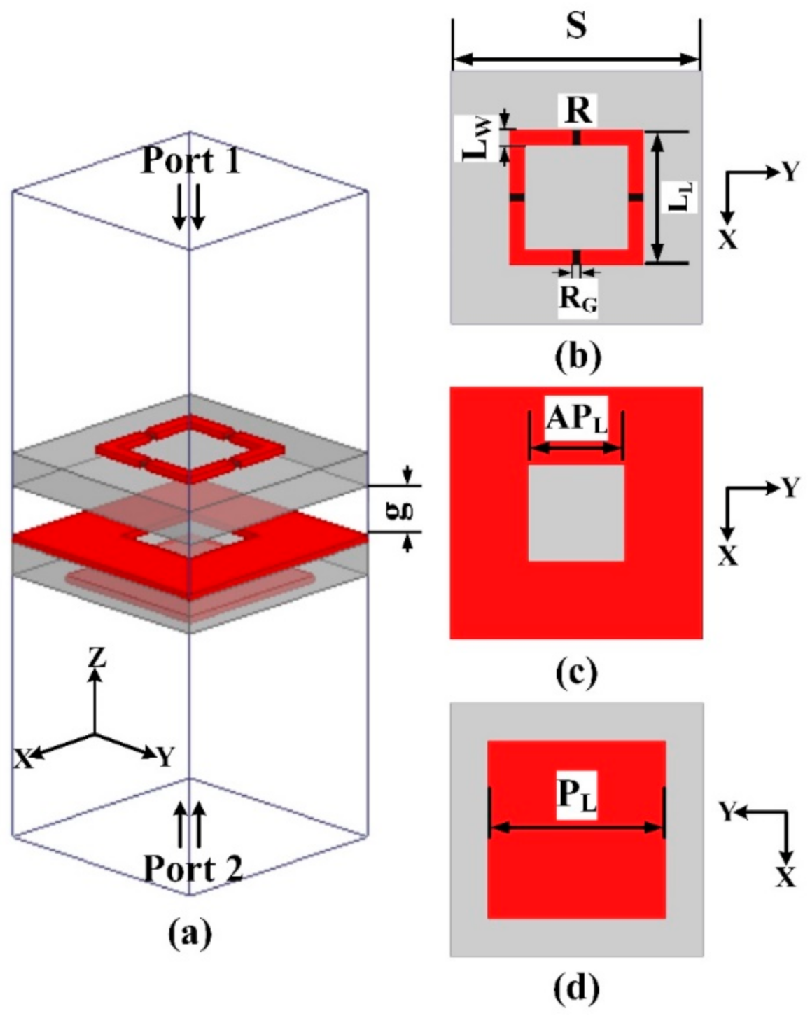
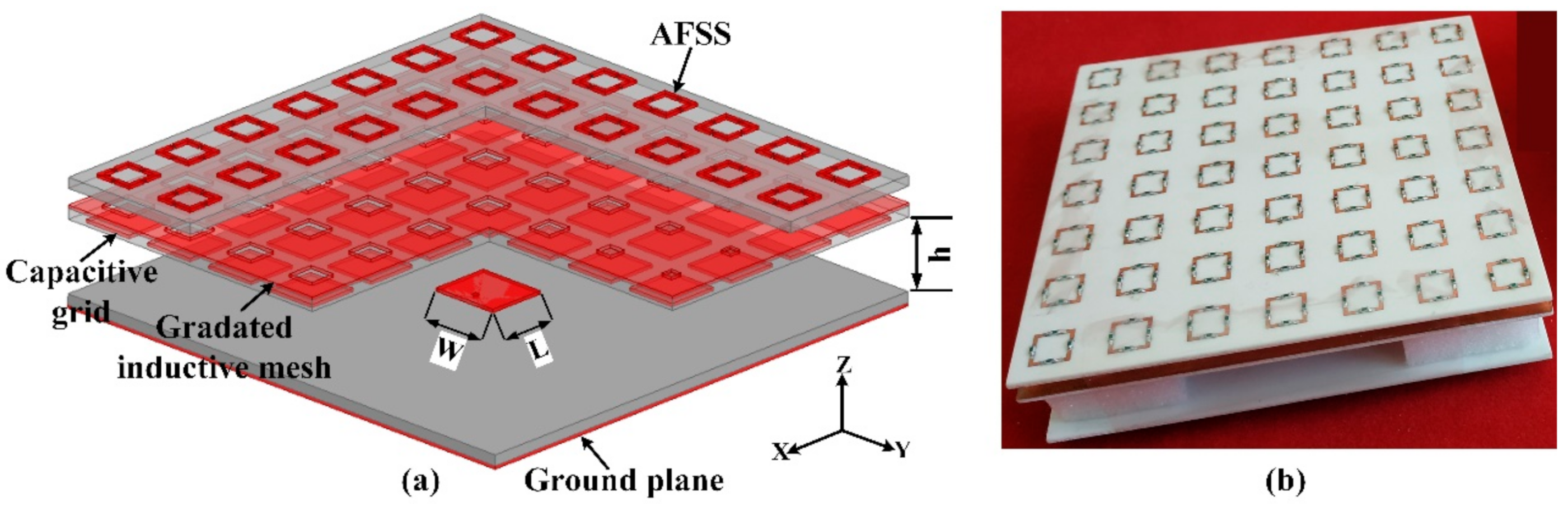
2. Unit Cell Design and Proposed FPC Antenna
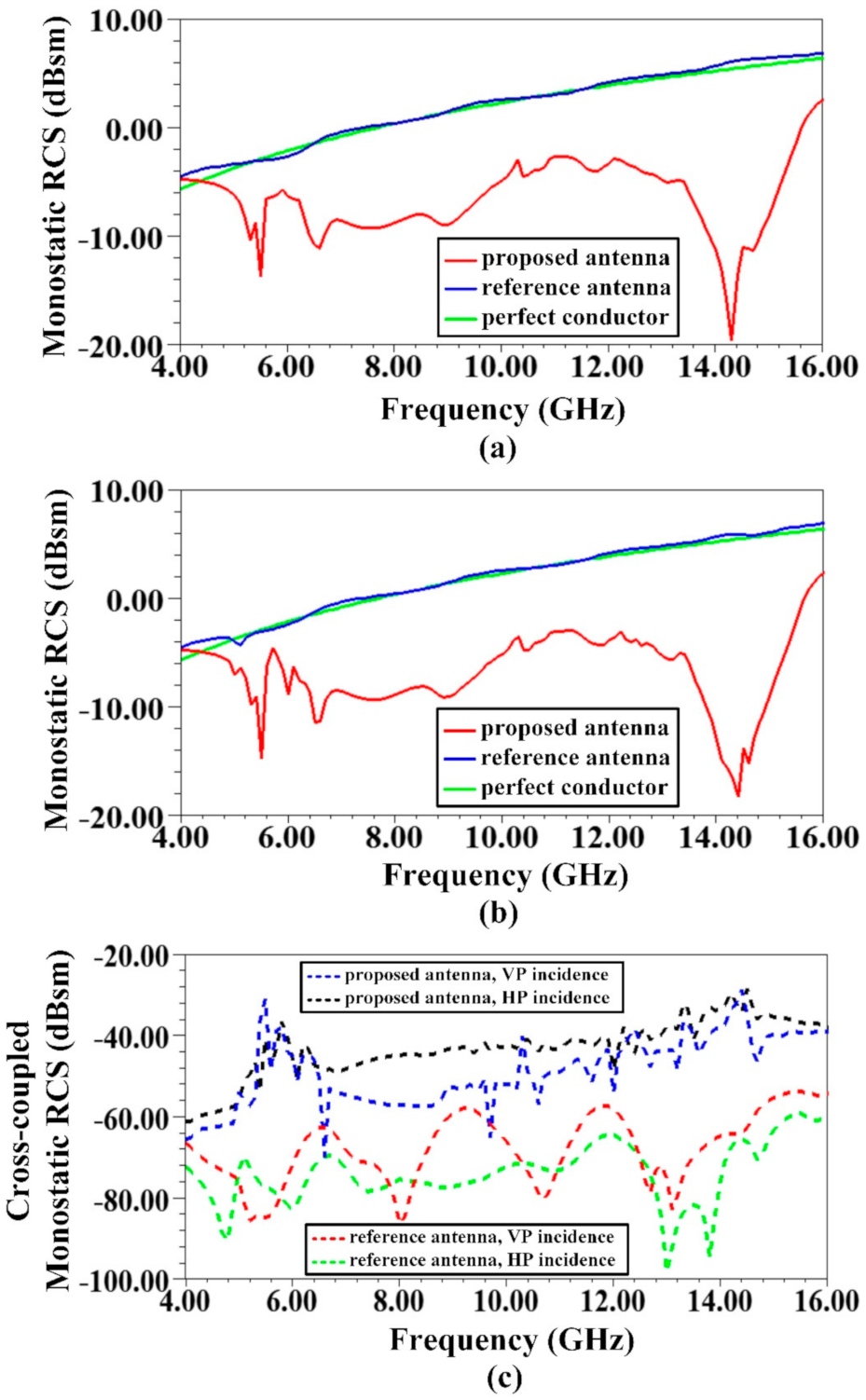
- Wideband monostatic RCS reduction.
- Appropriate gain enhancement.
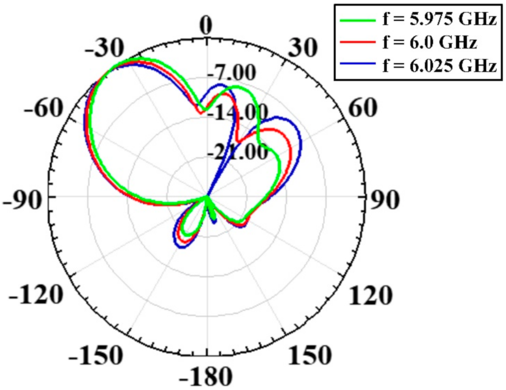
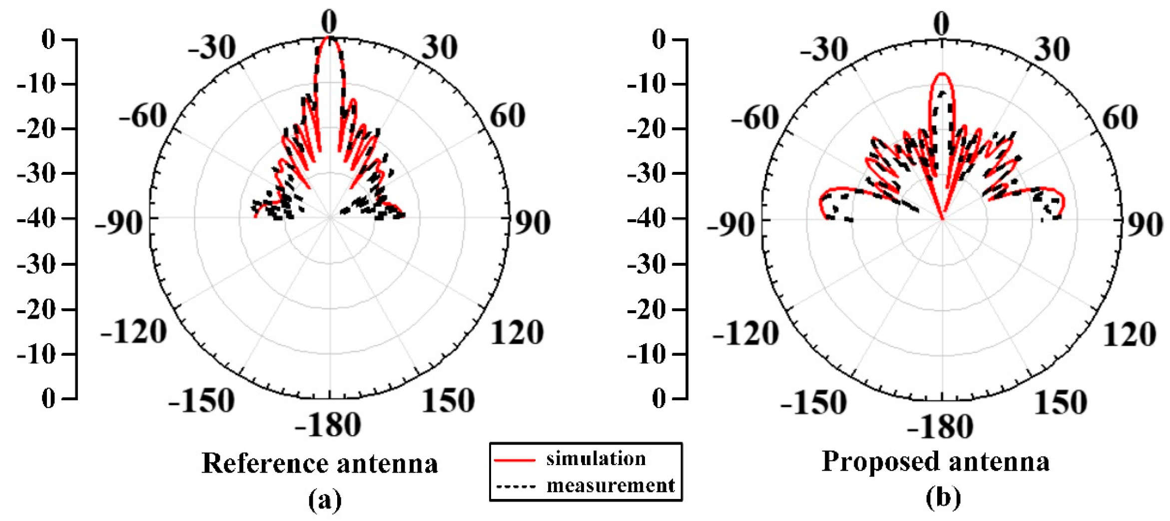
- Off-broadside peak radiation.
- Reduced cavity height (λ/4).
- Symmetric in design, so that wideband RCS reduction can be achieved for both polarizations of the incident radar wave, i.e., transverse electric (TE) and transverse magnetic (TM), and
- It should give 0 reflection phase so that once mounted above patch antenna, the cavity height can be reduced to λ/4.
- The achieved reflection phase gradient was meagre and seemed insufficient to achieve significant beam tilt.
- The reflection phase values were not supportive of reduced cavity height.
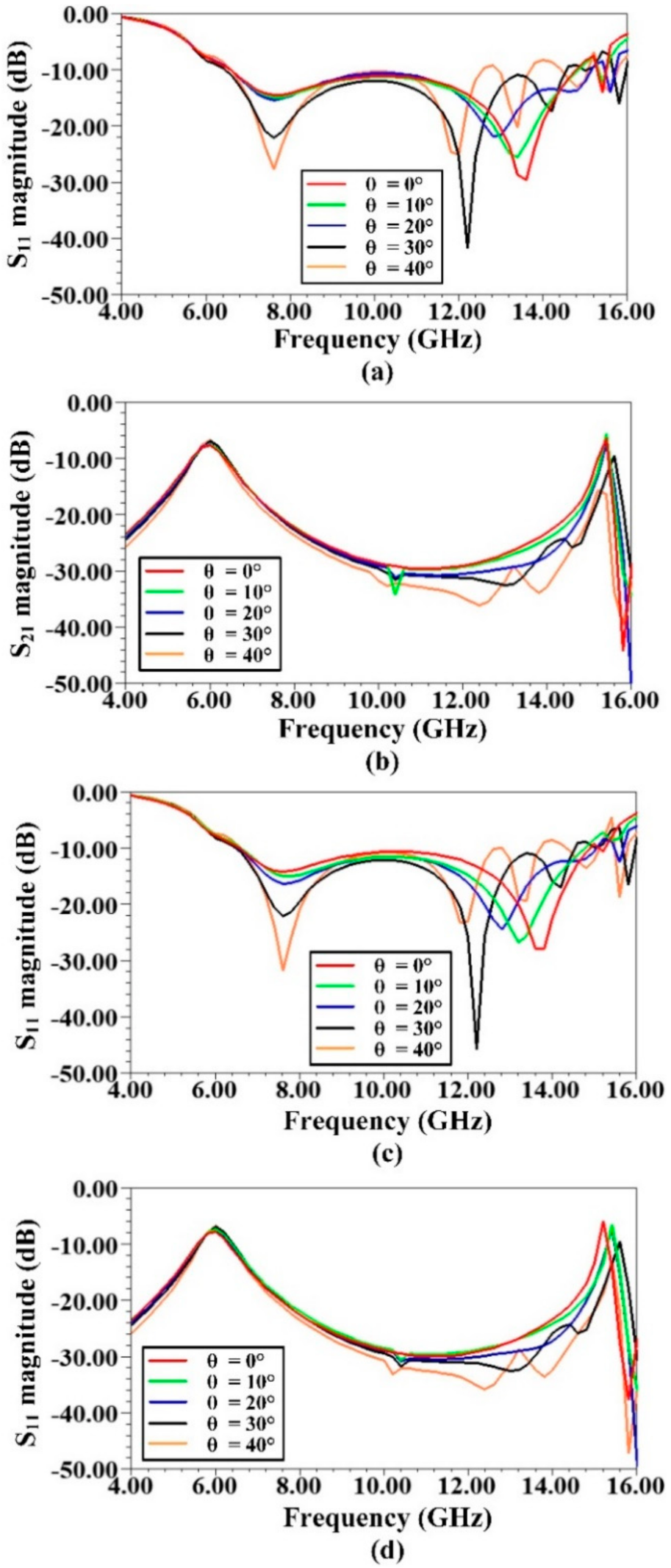
- For incoming wave absorption (port 1 to port 2), reflection (S11) magnitude as well as transmission (S21) magnitude had to be below −10 dB over a wide range of frequencies, to achieve at least 80% of incident wave absorption.
- In the transmission mode (port 2 to port 1), reflection coefficient (S22) had to show high partial reflectivity as well as progressive phase over the gradated apertures, at operating frequency, to achieve high gain as well as off-broadside radiation.
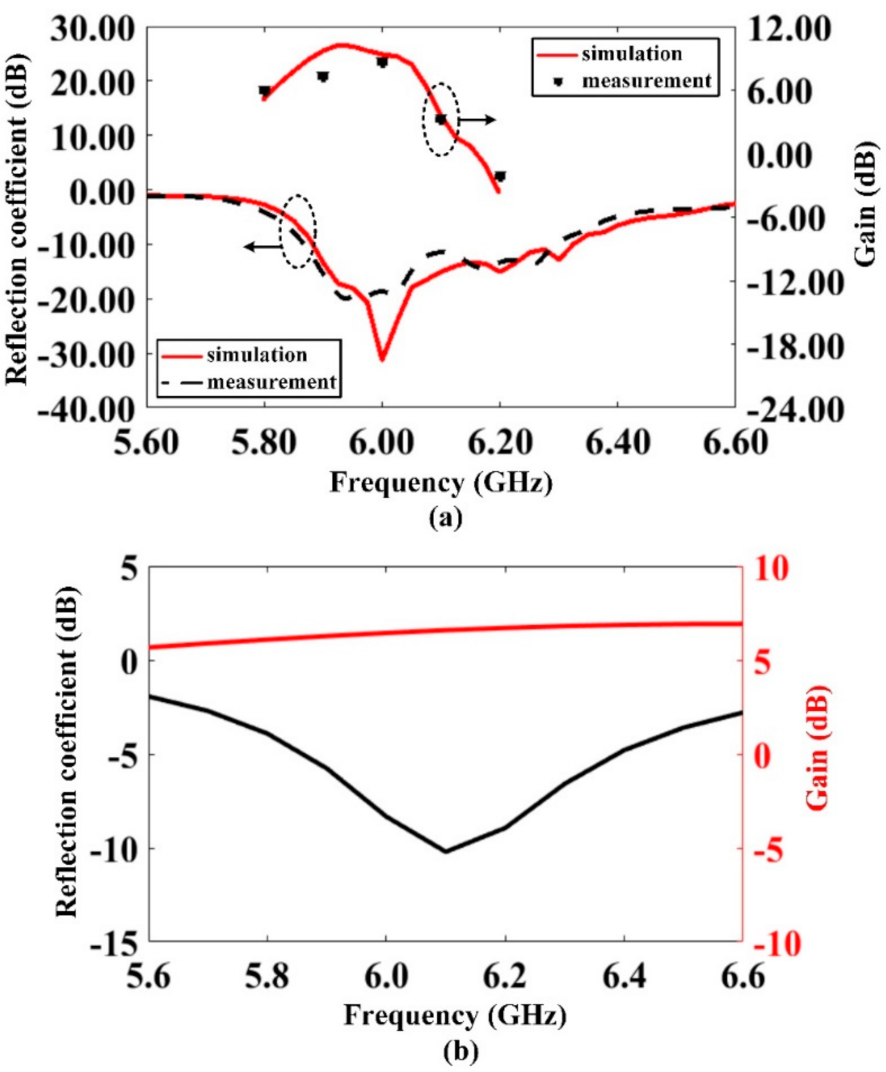
3. Simulation and Experimental Results
4. Discussion
5. Conclusions
Author Contributions
Funding
Institutional Review Board Statement
Informed Consent Statement
Data Availability Statement
Conflicts of Interest
References
- Wiesbeck, W.; Heidrich, E. Influence of antennas on the radar cross section of camouflaged aircraft. In Proceedings of the 92 International Conference on Radar, Brighton, UK, 12–13 October 1992; pp. 122–125. [Google Scholar]
- Wilsen, C.; Davidson, D. The radar cross section reduction of microstrip patches. In Proceedings of the IEEE AFRICON’96, Stellenbosch, South Africa, 27 September 1996; pp. 730–733. [Google Scholar]
- Jia, Y.; Liu, Y.; Gong, S.-X.; Hong, T.; Yu, D. Printed UWB end-fire Vivaldi antenna with low RCS. Prog. Electromagn. Res. 2013, 7, 11–20. [Google Scholar] [CrossRef]
- Jiang, W.; Liu, Y.; Gong, S.; Hong, T. Application of bionics in antenna radar cross section reduction. IEEE Antennas Wirel. Propag. Lett. 2009, 8, 1275–1278. [Google Scholar] [CrossRef]
- Hu, S.; Chen, H.; Law, C.L.; Shen, Z.; Zhu, L.; Zhang, W.; Dou, W. Backscattering cross section of ultrawideband antennas. IEEE Antennas Wirel. Propag. Lett. 2007, 6, 70–73. [Google Scholar] [CrossRef]
- Thakare, Y. Design of fractal patch antenna for size and radar cross-section reduction. IET Microw. Antennas Propag. 2010, 4, 175–181. [Google Scholar] [CrossRef]
- Wang, W.; Gong, S.; Wang, X.; Guan, Y.; Jiang, W. Differential evolution algorithm and method of moments for the design of low-RCS antenna. IEEE Antennas Wirel. Propag. Lett. 2010, 9, 295–298. [Google Scholar] [CrossRef]
- Yang, J.; Shen, Z. A thin and broadband absorber using double-square loops. IEEE Antennas Wirel. Propag. Lett. 2007, 6, 388–391. [Google Scholar] [CrossRef]
- Miao, Z.; Huang, C.; Ma, X.; Pu, M.; Ma, X.; Zhao, Q.; Luo, X. Design of a patch antenna with dual-band radar cross-section reduction. Microw. Opt. Technol. Lett. 2012, 54, 2516–2520. [Google Scholar] [CrossRef]
- Pozar, D.M. RCS reduction for a microstrip antenna using a normally biased ferrite substrate. IEEE Microw. Guided Wave Lett. 1992, 2, 196–198. [Google Scholar] [CrossRef]
- Genovesi, S.; Costa, F.; Monorchio, A. Low-profile array with reduced radar cross section by using hybrid frequency selective surfaces. IEEE Trans. Antennas Propag. 2012, 60, 2327–2335. [Google Scholar] [CrossRef]
- Costa, F.; Genovesi, S.; Monorchio, A. A frequency selective absorbing ground plane for low-RCS microstrip antenna arrays. Prog. Electromagn. Res. 2012, 126, 317–332. [Google Scholar] [CrossRef]
- Costa, F.; Monorchio, A. A frequency selective radome with wideband absorbing properties. IEEE Trans. Antennas Propag. 2012, 60, 2740–2747. [Google Scholar] [CrossRef]
- Chen, H.; Hou, X.; Deng, L. Design of frequency-selective surfaces radome for a planar slotted waveguide antenna. IEEE Antennas Wirel. Propag. Lett. 2009, 8, 1231–1233. [Google Scholar] [CrossRef]
- Li, Y.-Q.; Zhang, H.; Fu, Y.-Q.; Yuan, N.-C. RCS reduction of ridged waveguide slot antenna array using EBG radar absorbing material. IEEE Antennas Wirel. Propag. Lett. 2008, 7, 473–476. [Google Scholar]
- Zhang, J.; Wang, J.; Chen, M.; Zhang, Z. RCS reduction of patch array antenna by electromagnetic band-gap structure. IEEE Antennas Wirel. Propag. Lett. 2012, 11, 1048–1051. [Google Scholar] [CrossRef]
- Gao, Q.; Yin, Y.; Yan, D.-B.; Yuan, N.-C. Application of metamaterials to ultra-thin radar-absorbing material design. Electron. Lett. 2005, 41, 936–937. [Google Scholar] [CrossRef]
- Zheng, Y.; Gao, J.; Cao, X.; Yuan, Z.; Yang, H. Wideband RCS reduction of a microstrip antenna using artificial magnetic conductor structures. IEEE Antennas Wirel. Propag. Lett. 2015, 14, 1582–1585. [Google Scholar] [CrossRef]
- Ren, J.; Gong, S.; Jiang, W. Low-RCS monopolar patch antenna based on a dual-ring metamaterial absorber. IEEE Antennas Wirel. Propag. Lett. 2017, 17, 102–105. [Google Scholar] [CrossRef]
- Gao, J.; Zhao, Y.; Liu, T. A low RCS waveguide slot antenna array with metamaterial absorber. IEEE Trans. Antennas Propag. 2015. [Google Scholar] [CrossRef]
- Liu, Y.; Zhao, X. Perfect absorber metamaterial for designing low-RCS patch antenna. IEEE Antennas Wirel. Propag. Lett. 2014, 13, 1473–1476. [Google Scholar] [CrossRef]
- Liu, T.; Cao, X.; Gao, J.; Zheng, Q.; Li, W.; Yang, H. RCS reduction of waveguide slot antenna with metamaterial absorber. IEEE Trans. Antennas Propag. 2012, 61, 1479–1484. [Google Scholar] [CrossRef]
- Liu, Y.; Li, K.; Jia, Y.; Hao, Y.; Gong, S.; Guo, Y.J. Wideband RCS reduction of a slot array antenna using polarization conversion metasurfaces. IEEE Trans. Antennas Propag. 2015, 64, 326–331. [Google Scholar] [CrossRef]
- Zheng, Q.; Guo, C.; Ding, J. Wideband and low RCS circularly polarized slot antenna based on polarization conversion of metasurface for satellite communication application. Microw. Opt. Technol. Lett. 2018, 60, 679–685. [Google Scholar] [CrossRef]
- Pan, W.; Huang, C.; Chen, P.; Ma, X.; Hu, C.; Luo, X. A low-RCS and high-gain partially reflecting surface antenna. IEEE Trans. Antennas Propag. 2013, 62, 945–949. [Google Scholar] [CrossRef]
- Jiang, H.; Xue, Z.; Li, W.; Ren, W.; Cao, M. Low-RCS high-gain partially reflecting surface antenna with metamaterial ground plane. IEEE Trans. Antennas Propag. 2016, 64, 4127–4132. [Google Scholar]
- Mu, J.; Wang, H.; Wang, H.Q.; Huang, Y. Low-RCS and gain enhancement design of a novel partially reflecting and absorbing surface antenna. IEEE Antennas Wirel. Propag. Lett. 2017, 16, 1903–1906. [Google Scholar] [CrossRef]
- Huang, C.; Pan, W.; Ma, X.; Luo, X. A frequency reconfigurable directive antenna with wideband low-RCS property. IEEE Trans. Antennas Propag. 2016, 64, 1173–1178. [Google Scholar] [CrossRef]
- Jia, Y.; Liu, Y.; Zhang, W.; Wang, J.; Gong, S.; Liao, G. High-Gain Fabry-Perot Antennas with Wideband Low Monostatic RCS Using Phase Gradient Metasurface. IEEE Access 2018, 7, 4816–4824. [Google Scholar] [CrossRef]
- Sumantyo, J.T.S. Design of tilted beam circularly polarized antenna for CP-SAR sensor onboard UAV. In Proceedings of the 2016 International Symposium on Antennas and Propagation (ISAP), Okinawa, Japan, 24–28 October 2016; pp. 658–659. [Google Scholar]
- Lee, C.U.; Noh, G.; Ahn, B.; Yu, J.-W.; Lee, H.L. Tilted-Beam Switched Array Antenna for UAV Mounted Radar Applications with 360° Coverage. Electronics 2019, 8, 1240. [Google Scholar] [CrossRef]
- Hassan, T.; Khan, M.U.; Attia, H.; Sharawi, M.S. An FSS Based Correlation Reduction Technique for MIMO Antennas. IEEE Trans. Antennas Propag. 2018, 66, 4900–4905. [Google Scholar] [CrossRef]
- Thummaluru, S.R.; Kumar, R.; Chaudhary, R.K. Isolation enhancement and radar cross section reduction of MIMO antenna with frequency selective surface. IEEE Trans. Antennas Propag. 2018, 66, 1595–1600. [Google Scholar] [CrossRef]
- Mehmood, A.; Karabey, O.H.; Jakoby, R. Dielectric resonator antenna with tilted beam. IEEE Antennas Wirel. Propag. Lett. 2016, 16, 1119–1122. [Google Scholar] [CrossRef]
- Foroozesh, A.; Shafai, L. Investigation into the effects of the patch-type FSS superstrate on the high-gain cavity resonance antenna design. IEEE Trans. Antennas Propag. 2009, 58, 258–270. [Google Scholar] [CrossRef]
- Costa, F.; Monorchio, A.; Manara, G. Analysis and design of ultra thin electromagnetic absorbers comprising resistively loaded high impedance surfaces. IEEE Trans. Antennas Propag. 2010, 58, 1551–1558. [Google Scholar] [CrossRef]
- Nakano, H.; Mitsui, S.; Yamauchi, J. Tilted-beam high gain antenna system composed of a patch antenna and periodically arrayed loops. IEEE Trans. Antennas Propag. 2014, 62, 2917–2925. [Google Scholar] [CrossRef]
- Ghasemi, A.; Burokur, S.N.; Dhouibi, A.; de Lustrac, A. High beam steering in Fabry–Pérot leaky-wave antennas. IEEE Antennas Wirel. Propag. Lett. 2013, 12, 261–264. [Google Scholar] [CrossRef]
- Ourir, A.; Burokur, S.; de Lustrac, A. Phase-varying metamaterial for compact steerable directive antennas. Electron. Lett. 2007, 43, 493–494. [Google Scholar] [CrossRef]
- Qin, F.; Gao, S.; Mao, C.; Wei, G.; Xu, J.; Li, J. Low-profile high-gain tilted-beam Fabry-Perot antenna. In Proceedings of the 2015 9th European Conference on Antennas and Propagation (EuCAP), Lisbon, Portugal, 13–17 April 2015; pp. 1–5. [Google Scholar]
- Li, W.-Q.; Cao, X.-Y.; Gao, J.; Zhang, Z.; Cong, L.-L. Broadband RCS reduction and gain enhancement microstrip antenna using shared aperture artificial composite material based on quasi-fractal tree. IET Microw. Antennas Propag. 2016, 10, 370–377. [Google Scholar] [CrossRef]
- Mailloux, R.J. Phased Array Antenna Handbook; Artech House: Norwood, MA, USA, 2017. [Google Scholar]
- Zhang, L.; Wan, X.; Liu, S.; Yin, J.Y.; Zhang, Q.; Wu, H.T.; Cui, T.J. Realization of low scattering for a high-gain Fabry–Perot antenna using coding metasurface. IEEE Trans. Antennas Propag. 2017, 65, 3374–3383. [Google Scholar] [CrossRef]


| APL (mm) | 2.4 | 3.5 | 5.1 | 5.5 | 5.8 | 6.2 | 6.6 |
| Reflection Phases | 97.72° | 86.24° | 10.56° | −23.89° | −38.38° | −63.91° | −81.57° |
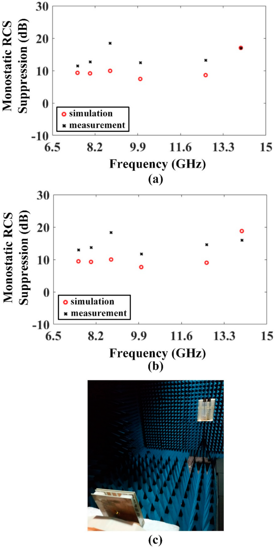
| Ser. | Tested Frequencies (GHz) | RCS Suppression (dB) | |||
|---|---|---|---|---|---|
| VP Incident Wave | HP Incident Wave | ||||
| Simulation | Measurement | Simulation | Measurement | ||
| 1. | 7.5 | 9.32 | 11.49 | 9.44 | 12.92 |
| 2. | 8 | 9.15 | 12.72 | 9.27 | 13.73 |
| 3. | 8.8 | 9.93 | 18.48 | 10 | 18.3 |
| 4. | 10 | 7.43 | 12.5 | 7.66 | 11.71 |
| 5. | 12.6 | 8.61 | 13.16 | 9 | 14.51 |
| 6. | 14 | 17.02 | 16.95 | 18.78 | 16 |
| Mean RCS Suppression (dB) | 10.24 | 14.22 | 10.69 | 14.53 | |
| Ref. | Size | Gain | Operating Frequency | RCS Reduction Band (% BW) | Average RCS Reduction | Beam Deflection |
|---|---|---|---|---|---|---|
| [25] | 2.3 λ × 2.3 λ × 0.58 λ | 13.2 dB | 11.5 GHz | 6–14 GHz (80%) | 10 dB | No |
| [28] | 2.79 λ × 2.79 λ × 0.68 λ | 13.7 dB | 9.05–10 GHz (reconfigurable) | 7–14 GHz (66.67%) | unspecified | No |
| [29] | 3.36 λ × 3.36 λ × 0.7 λ | 17.9 dB | 8.4 GHz | 7–15 GHz (72.73%) | 9.9 dB | No |
| [26] | 3.7 λ × 3.7 λ × 0.73 λ | 18.4 dB | 10 GHz | 8–17 GHz (72%) | 13 dB | No |
| [43] | 3.67 λ × 3.67 λ × 0.62 λ | 19.8 dB | 10 GHz | 8–12 GHz (40%) | 8.76 dB | No |
| This work | 2.1 λ × 2.1 λ × 0.26 λ | 9.4 dB | 6 GHz | 4–16 GHz (120%) | 8.5 dB (VP) 8.8 dB (HP) | Yes (−38°) |
Publisher’s Note: MDPI stays neutral with regard to jurisdictional claims in published maps and institutional affiliations. |
© 2021 by the authors. Licensee MDPI, Basel, Switzerland. This article is an open access article distributed under the terms and conditions of the Creative Commons Attribution (CC BY) license (http://creativecommons.org/licenses/by/4.0/).
Share and Cite
Umair, H.; Latef, T.B.A.; Yamada, Y.; Hassan, T.; Mahadi, W.N.L.B.W.; Othman, M.; Kamardin, K.; Hussein, M.I. Quarter Wavelength Fabry–Perot Cavity Antenna with Wideband Low Monostatic Radar Cross Section and Off-Broadside Peak Radiation. Appl. Sci. 2021, 11, 1053. https://doi.org/10.3390/app11031053
Umair H, Latef TBA, Yamada Y, Hassan T, Mahadi WNLBW, Othman M, Kamardin K, Hussein MI. Quarter Wavelength Fabry–Perot Cavity Antenna with Wideband Low Monostatic Radar Cross Section and Off-Broadside Peak Radiation. Applied Sciences. 2021; 11(3):1053. https://doi.org/10.3390/app11031053
Chicago/Turabian StyleUmair, Hassan, Tarik Bin Abdul Latef, Yoshihide Yamada, Tayyab Hassan, Wan Nor Liza Binti Wan Mahadi, Mohamadariff Othman, Kamilia Kamardin, and Mousa I. Hussein. 2021. "Quarter Wavelength Fabry–Perot Cavity Antenna with Wideband Low Monostatic Radar Cross Section and Off-Broadside Peak Radiation" Applied Sciences 11, no. 3: 1053. https://doi.org/10.3390/app11031053
APA StyleUmair, H., Latef, T. B. A., Yamada, Y., Hassan, T., Mahadi, W. N. L. B. W., Othman, M., Kamardin, K., & Hussein, M. I. (2021). Quarter Wavelength Fabry–Perot Cavity Antenna with Wideband Low Monostatic Radar Cross Section and Off-Broadside Peak Radiation. Applied Sciences, 11(3), 1053. https://doi.org/10.3390/app11031053