1. Introduction
It is essential to implement regenerative braking in all types of electric and hybrid vehicles to extend traveling distance which is hindered by a limited battery capacity [
1,
2]. Mostly, regenerative braking is applied during downhill driving and when speed limitation is needed [
3,
4]. Providing appropriate deceleration or braking in downhill driving, regenerative braking brings both energy regain and safety with its retarding effect [
5]. Extra traveling distance due to regaining of some spent energy back is one of the solutions for “range anxiety” as well as for the total efficiency of an electric power train [
6,
7,
8]. An optimistic guess is to provide 10% to 15% of energy back to the battery by regeneration [
9]. Basically, there are some inherent limitations of regenerative braking such as the braking capability of the vehicle electric powertrain, the battery’s state-of-charge (SoC), ambient temperature, etc. [
10,
11]. Firstly, regenerative braking is not implemented with a fully charged battery and causes heating for some operation schemes. So, there must always be room for extra charging kept in the battery capacity. Vehicle weight distribution while cornering or braking is also a limiting factor for regeneration performance [
12]. Of course, regenerative braking efficiency is highly related to operation regions of electrical machines and their power electronic systems [
13]. Most of all, efficiency is limited at lower speeds due to reduced induced voltage and low power amount. To mitigate those disadvantages and improve the performance of regenerative braking, a number of publications are presented in the literature.
In [
14], a new method for regenerative braking in electric vehicles is presented. The proposed approach is a combined version of single-switch, two-switch, three-switch, and plugging operations in brushless direct current (BLDC) machines and the coordination of them according to their higher performance regions. Those operation regions are verified by means of a criteria consisting of boosting the converter ratio, braking torque, maximum conversion ratio, stopping time, and energy recovery value. In [
13], an integrated fuzzy and PID (proportional-integral-derivative) controller is implemented for braking torque distribution. The proposed method brings a better performance of regenerative braking over conventional control methods related to robustness and efficiency. In addition, for fuzzified input parameters, the battery SoC, speed of vehicle, and brake force are selected. In another publication, a real-time range indicator system is developed and an on-board estimation algorithm for SoC and travel range is implemented according to real-time data captured from environmental units [
15]. Weather conditions, rolling resistance, ambient temperature, power train efficiency, real-time traffic data, and regenerative-frictional braking force distribution are taken into account for the presented study. In [
16], an energy optimized driving strategy is realized for heavy-duty vehicles. For model predictive control (MPC) method, regenerative braking is used as an optimization parameter. Another study is about a braking force control strategy and a sharing algorithm between regenerative braking and frictional braking for maximizing regenerative braking efficiency [
12]. In [
17], the maximum regenerative braking force for a vehicle is obtained by analyzing the braking capability of a PM synchronous motor. The maximum regenerative braking effort is used as a constraint for a MPC. By means of that parameter, the braking torque value is determined according to driving tendencies of user. Furthermore, the emergency braking is implemented to provide the shortest stopping distance by using a sliding mode controller. Another publication is on the regenerative braking capacity of a specific electric machine at lower speeds by analyzing the limiting factor of regeneration [
18]. Additionally, a novel control approach based on the monitoring of a dc-link current of the motor controller is proposed to overcome the limitation and enable dynamic detection of a low-speed cutoff point (LSCP). In [
19], the regenerative braking performance of an electrical machine is enhanced by using a downshifting system at the machine operation points. A load commutated multilevel current source inverter fed open-ended winding induction motor drive with regeneration capability is presented in [
20]. The proposed approach is related to a decrease in the effect of low back EMF and increase in the amplitude of regenerative braking torque. In [
21], a slip-rate control strategy based on sliding mode control and braking force control strategy based on the Economic Commission for Europe’s (ECE) regulation are presented to improve the efficiency of recovered electrical energy. A novel two-boost method which is exploiting the motor converter as a cascade connected two-level boost converter is asserted for BLDC motor regenerative braking [
22]. In [
23], a downshifting strategy is described to improve recovery energy by adjusting operating regions of electric motor for electric and hybrid vehicles with stepped automatic transmissions. The method proposal includes a downshifting control strategy using cluster-based stochastic dynamic programming (SDP).
Although numerous methods and approaches are presented in recent literature, most of them accommodate complex mathematical modeling or additional circuits and of course, those extra features hinder the possibilities of practical application of regenerative braking. The suitable solution implies not using any additional circuits, implementing a braking control strategy without compromising the regenerative braking performance [
24]. The fundamental principle of regeneration is relied on using an inverter as a boost converter and machine stator winding as boosting inductors. However, this method has some limitations due to the nonlinear effects of the drive circuit. The limitations of voltage boosting are mainly caused by SoC and the thermal structure of a battery pack, winding resistance, non-ideal effects, and voltage drops of semiconductors [
25]. Battery heating is dependent on ambient and operation conditions [
26]. Basically, because of the electrochemical structure, heating is a major deteriorating factor for any battery type. In [
27], internal resistance and capacity of battery are investigated for different operation conditions. It is indicated that temperature rise due to ambient and/or operation conditions negatively affect power and the energy capacity of a battery and vehicle performance consequently. Sometimes an improper regenerative braking operation may cause overheating which disrupts the overall battery performance [
28]. A mathematical approach to single-switch regeneration scheme with maximum conversion ratio for BLDC motors is proposed in [
13]. However, the change of internal resistance of battery-related heating is not taken into account. In [
15], for a commercial electric vehicle (Nissan Leaf), the variation of battery internal resistance is presented for different SoC values during charging and discharging. Battery open circuit voltage depending on SoC and internal resistance shows the effects of ambient temperature and operation conditions. Temperature rise, i.e., heating, affects the performance, reliability, and life span of a battery package. Its effect on internal resistance also hampers regenerative braking efforts [
19]. Tracking of internal resistance variation and controlling battery performance improve the quality of regenerative braking.
In this study, all constraints emerge from non-ideal elements of the motor control inverter, which is reduced to a single-switch boost converter model, such as on-state resistances, threshold voltage drops, and dynamic variation of battery internal resistance are taken into account to achieve maximum regeneration at the specific duty ratio. A resistance-temperature characteristic [ (), T (C)] determined by the online tracking of the battery temperature is used to define the dynamic value of internal resistance for obtaining specific duty ratio which enables the maximum energy recovery during braking. The proposed model of the machine drive system is used for defining the constraints and upper limits. An accurate and dynamic circuit model can reflect the optimizing battery run time and energy recovery performance.
The rest of this paper is organized as follows: In
Section 2, the principle of regenerative braking in a BLDC machine is presented. The braking strategy and circuit analysis are presented in
Section 3. In
Section 4, the experimental studies and results of the proposed method are presented. Additionally, the findings and comparative results are provided in
Section 4. Finally, the conclusion is presented in
Section 5. The results of the experimental study on the proposed method provide some important clues for the high efficient regenerative braking performance on BLDC machines.
2. Principle of Regenerative Braking in BLDC Machine
Regenerative braking is an essential feature of electric vehicles. Thanks to recovering energy via the generator operation of electric propulsion motor and boosting operation of the motor driver, it is possible to regain some part of kinetic energy as electrical energy for battery charging. Besides, it creates a proper braking effect particularly at higher speeds and increases overall efficiency. At a given speed, kinetic energy due to mass and rotating parts of a vehicle can be directed to battery charging while a braking action is applied. Energy, which causes the deceleration of a vehicle is partly recovered to charging the battery pack. Of course, the efficiency of generated electrical energy is dependent on combined operations of the electrical machine and power electronic circuit. If the battery is fully charged, regenerated energy can be consumed in a braking resistor, i.e., dynamic braking. In this study, the kinetic energy storage is implemented by using a flywheel coupled to the BLDC machine, to simulate a light electric vehicle powertrain. So, the braking effect can be easily calculated from the known value of kinetic energy change. However, there are retardation effects in the system other than regenerative braking, namely bearing friction and ferromagnetic (iron) loss due to interaction between stator magnetic core and rotor permanent magnets. The analysis can be complex due to the decomposition of those retarding components. To overcome this problem, a slotless BLDC motor topology which has negligible iron loss, is chosen. This way, the kinetic energy at the start of deceleration, the retarding effect of bearings, and the applied regenerative braking can be easily calculated. The regenerative braking action of a BLDC machine, which is driving a flywheel can be summarized as:
where
,
,
,
,
,
,
are the total inertia of rotating system, angular speed at the starting of deceleration, regeneration efficiency, instantaneous DC-link voltage, i.e., battery terminal voltage, instantaneous DC-link current, i.e., battery charging current, deceleration time to zero, and frictional braking energy of bearings, respectively. Frictional braking energy can be determined by calculating the difference between the free deceleration time and the deceleration time with regenerative braking. It defined as:
where
and
are the frictional torque and angular distance taken during deceleration, respectively. The main source of that viscous friction is split roller bearings of the flywheel and there is a contribution from the bearings of motor. Thanks to slotless brushless DC motor topology, there are no losses due to commutator-brush and stator core-permanent magnet interactions.
3. Proposed Braking Strategy Based on Critical Duty Ratio Determination
In the proposed study, the model of BLDC machine inverter reduced to a single-switch boost converter circuit is used to elucidate the regenerative braking operation. Single switch is capable of producing required braking torque and better energy recovery in mid to high-speed range [
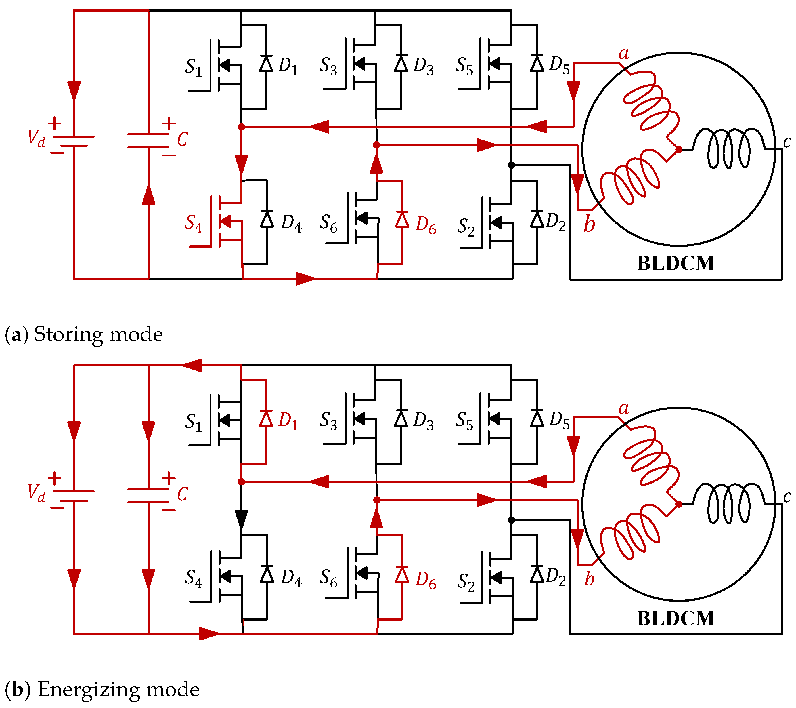
14]. The main principle during regenerative braking is to change the switching scheme to send the recovered energy back to battery, as it can be seen in
Figure 1, instead of using regular motor drive switching. The circuit operation includes two states of basic voltage boosting operation: Storing phase and energizing phase. In the regenerative braking operation at the energy storing state, the bottom MOSFETs,
,
, and
are switched accordingly to form a braking current waveform for providing proper braking performance. A nearly trapezoidal back electromotive force (EMF) is rectified and boosted by the motor driver converter for charging battery. When a bottom switch is off, the related top and bottom diodes transfer the power, i.e., current, to the battery.
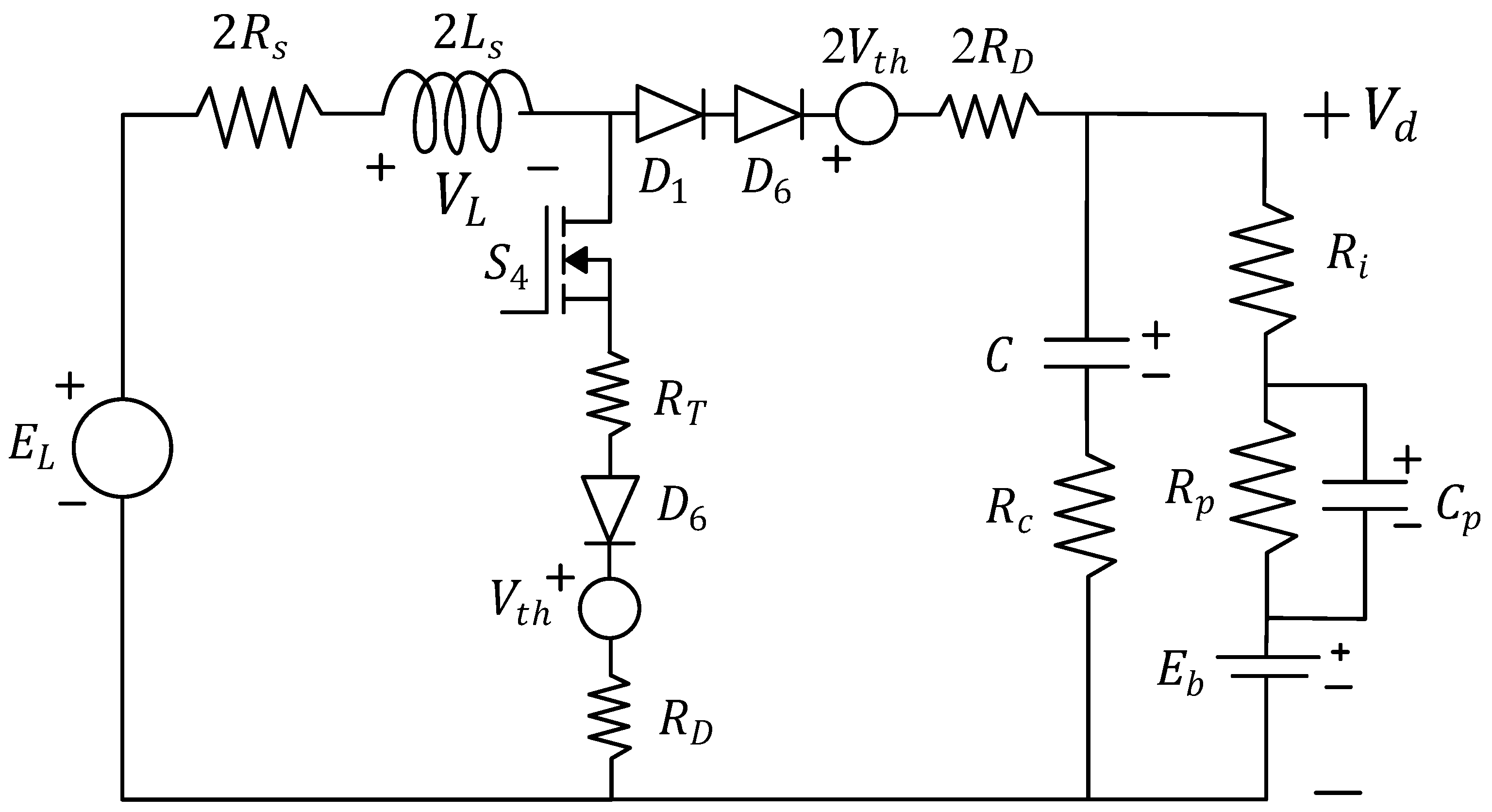
Figure 2 shows one operation interval of the converter, when
and
are on, the energy stored in the boosting inductor, i.e., the machine winding inductance, due to the terminal induced voltage. Then the current due to the sum of
and the inductor voltage is sent to the battery through
and
.
is the phase-to-phase or line-induced voltage during the generator operation of the BLDC motor and boosting the motor converter’s operation, given as:
where
is the maximum value of phase induced voltage. For trapezoidal back EMF motors,
is almost a constant voltage for each 60
overlapping of the phase induced voltages. For each 60
of commutation interval of the BLDC motor,
can be assumed a DC voltage then the converter is operated as a cascade connected rectifier – boost converter.
,
, and
are the phase-induced voltages of the phase a, phase b, and phase c, respectively.
can be assumed at its maximum for 60
intervals, coinciding with the energizing intervals of the BLDC motor. Thus, in the study, the same 60
conduction intervals provided by Hall sensors are used to define the range in which
is the highest then the boosting operation by a specified transistor is implemented.
By investigating the nature of regenerative braking, it is known that the boosted-induced voltage must compensate all non-ideal voltage drops in the principal circuit [
10]. This boosting action is modeled by using a non-ideal boost converter, which is demonstrated in
Figure 2 as a lump-parameter equivalent circuit. The non-ideal and parasitic components reduce the boosting action in their extent. For this reason, all nonlinear components should be taken into account while analysis of the circuit and modeling of the whole system are being derived. These analyses are crucial for the regenerative braking performance in order to increase the efficiency and to provide comfortable braking. The stator windings are used as the storing inductors in the boost-operated converter during regeneration. Naturally, the inductance value of those windings is higher than that of a conventional boost converter because the main intention is to design a BLDC motor stator winding, although the slotless topology of the motor diminishes the winding inductance to some extent. The main source of loss is the resistance value of the boosting inductor formed by stator windings because of the high number of winding turns. The approximate solutions are made by assuming small-ripple inductor current. The DC voltage gain solution is based on the inductor voltage variation along a switching period. Of course, a certain amount of loss is due to ESRs (equivalent series resistor) of DC-link capacitors. However, thanks to low a ESR and parallel connected DC-link capacitors, the loss caused by ESR is neglected for a steady-state DC solution. Another loss source is the ferromagnetic material of stator core, i.e., inductor core, this loss amount can be easily negligible but due to the slotless stator design. For the sake of simplicity of overall calculation and the implementation of control algorithm, those two loss components are not taken into account.
For steady-state voltage equation,
is the DC bus voltage which is the boosted value of
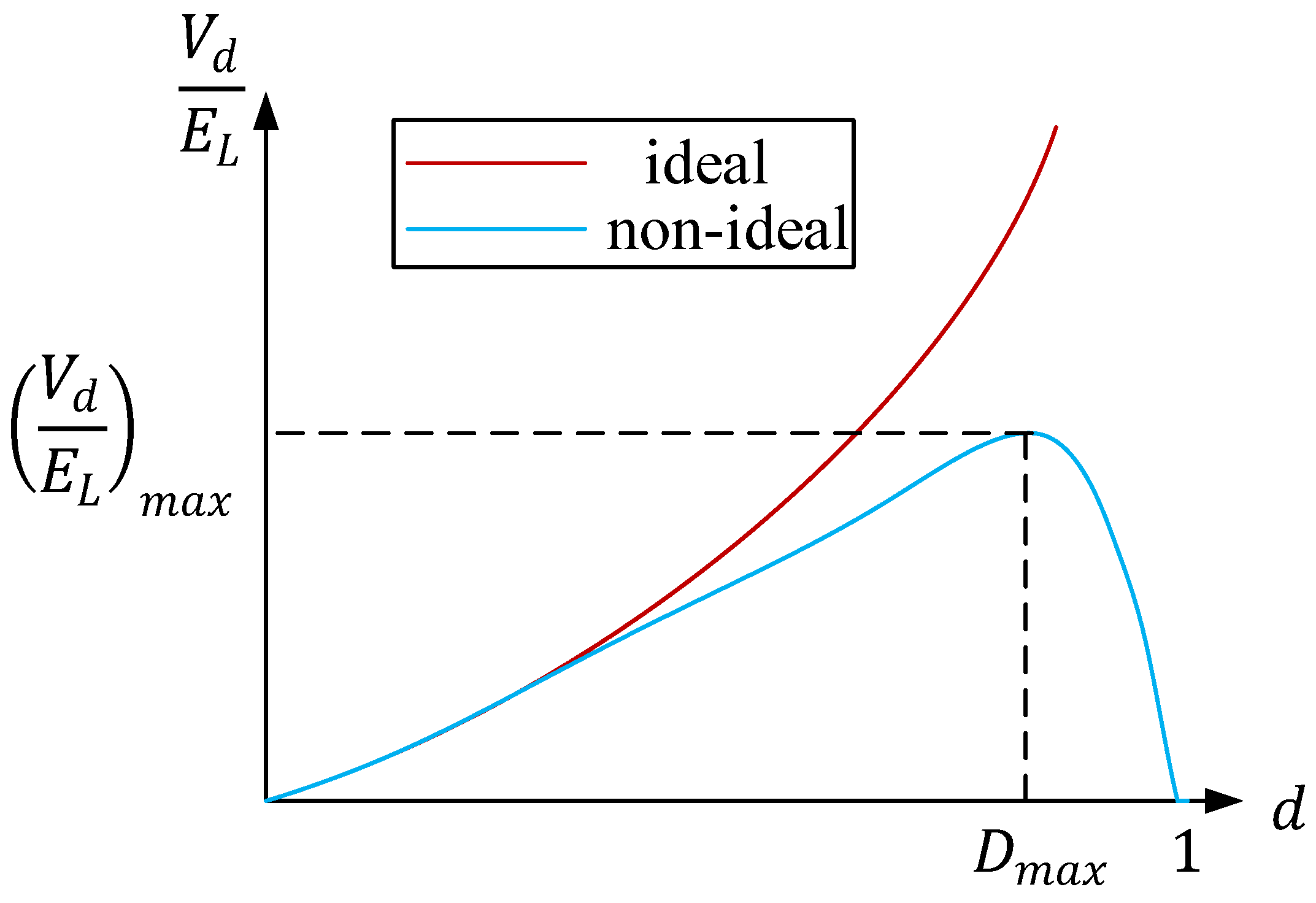
, the terminal back-EMF voltage. The most important performance parameter of the system is duty ratio which plays a role in providing enough current from boosted voltage to battery. Duty ratio has its maximum value that the boosted voltage decreases dramatically even as the duty ratio is increased as shown in
Figure 3. Ultimately the battery charging current during regeneration, i.e., braking current, must be controlled effectively in order to use high performance regenerative braking. The second limitation is back-EMF. Since
, which is the maximum duty cycle, depends on the (terminal resistance)/(battery internal resistance) boost conversion ratio, the internal resistance of the battery is an inevitable limitation.
When the regenerative braking equivalent circuit operates at a continuous conduction mode (CCM), the circuit can be analyzed by using two switching states as shown in
Figure 1. For both cases, all considerable parasitic and non-linear elements are included and the output voltage (
) and the load current (
) expressions are obtained as presented in Equations (4) and (5).
where
,
,
,
,
,
,
,
,
,
are the battery voltage, specific duty ratio, diode voltage drop, total battery internal resistance, MOSFET on–resistance, diode on–resistance, battery open circuit voltage, stator resistance, total electrochemical polarization resistance, and total electrochemical polarization capacitance, respectively. The duty ratio for maximum voltage gain can be calculated by equating the denominator of Equation (
4) to zero. Using the known values of Equation (
4) the required duty ratio for the maximum regeneration effect is calculated:
The essential performance parameter of the system is the specific duty ratio which provides a proper charging current for the battery pack. The value of
which is heavily dependent on the internal resistance of the battery has an important limitation. If non-ideal circuit parameters are not excluded, the PWM will be applied according to the steady-state and ideal machine equations. At this point, if the total internal resistance variation depending on the battery temperature is not known, an excessive current will charge the battery and cause the system to overheat and be damaged. Thus, in order to achieve a regenerative braking performance at maximum efficiency, the transfer functions including parasitic elements must be obtained. The line–to–output and control–to–output transfer functions of a boost converter model including parasitic elements are derived for regenerative braking operation at CCM. The line–to–output (
) and control–to–output (
) transfer functions have been obtained to examine the control performance of the specific duty ratio as shown in Equations (7) and (8).
where
,
,
, and
C are the terminal inductance, the equivalent series resistance of the DC filter capacitor, diode on–resistance, and capacitance, respectively. Moreover, the closed loop controller including the current and speed loops, the parameters are analyzed for the high stability, the maximum efficiency and the useful regenerative braking operation time. The
value is determined to be 0.78 and is used as a reference for the experimental studies. This value is assigned as a specific regenerative braking duty ratio at 25
C.
4. Experimental Study and Results
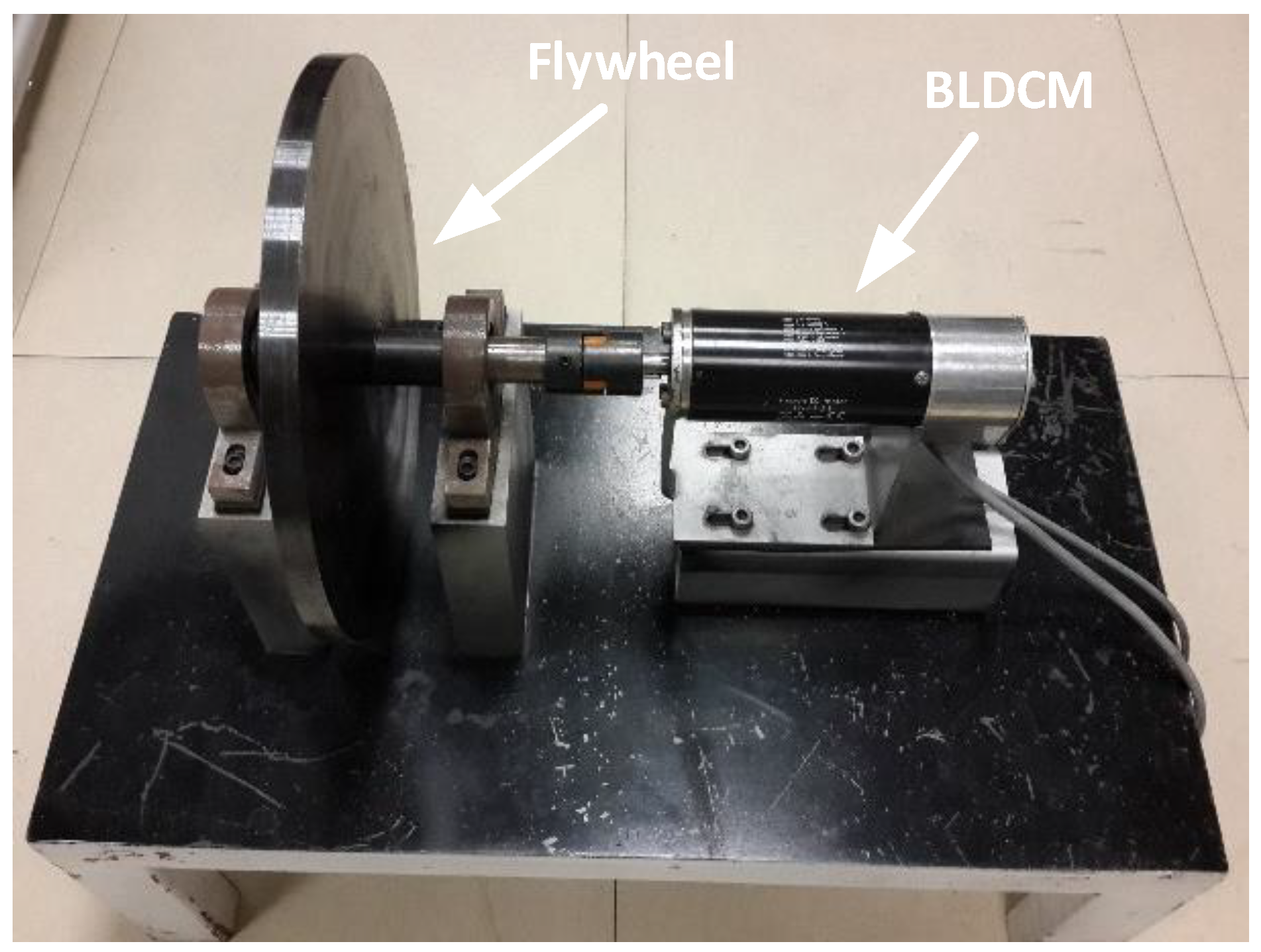
The practical features and feasibility of the regenerative braking circuit model of a BLDC machine drive system are evaluated by using an experimental setup which is presented in
Figure 4. Equations (4)–(6) and the braking control scheme are implemented via TMS320F28335 digital signal processor. Using the known parameters and the measured internal resistance value of Equation (
4), the required duty ratio for the maximum regeneration operation is calculated according to the regeneration command. In the meantime, instead of a PI controller, a hysteresis controller is activated and the PWM reference ratio is assigned as the calculated critical value. The converter has a maximum DC-link voltage of 13.5 V × 4, i.e., 54 V, and a rated RMS (root mean square) current of 5.3 A. The experiments are verified using the MAXON EC60 slotless type BLDC machine which is coupled to a specially designed flywheel, as shown in
Figure 4. The system specifications, BLDC machine, and flywheel parameters are given in
Table 1. The system specifications and machine parameters such as the terminal resistance, terminal inductance, on–resistance of MOSFET, on–resistance of diode, flywheel inertia have the values of 1.12
, 0.82 mH, 0.024
, 0.05
, 0.06089 kgm
, respectively.
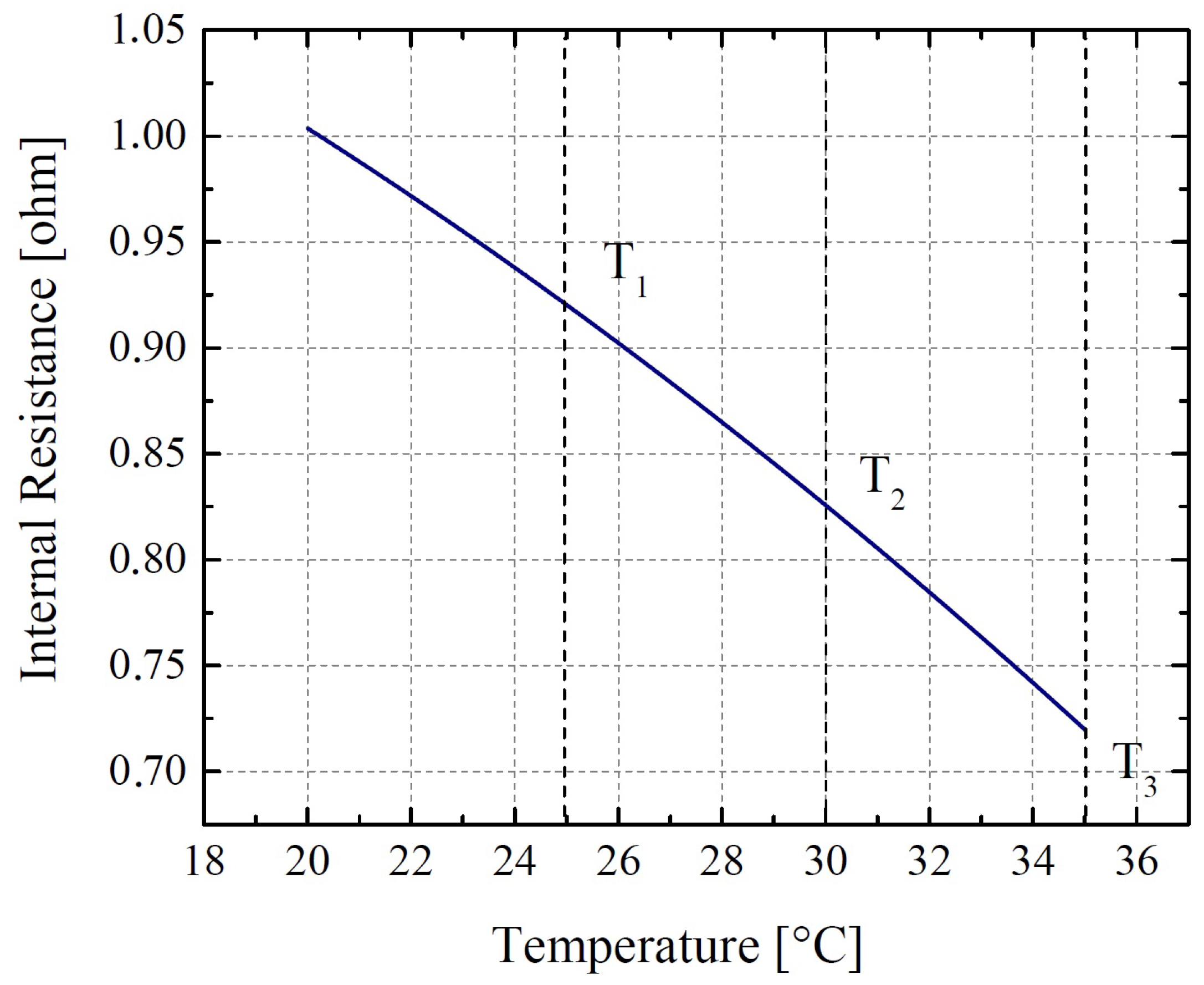
In the experiments, the temperature changes are carried out by using an ambient temperature controller for the same SoC values. The surface temperatures of the lead-acid batteries are captured by means of specific temperature sensors. Internal resistance variations are measured at reference points of 25
C, 30
C, and 35
C. These values are obtained as 0.909
, 0.837
, and 0.716
at the temperatures
,
, and
, respectively as shown in
Figure 5 In addition, the initial operation parameters are presented in
Table 2.
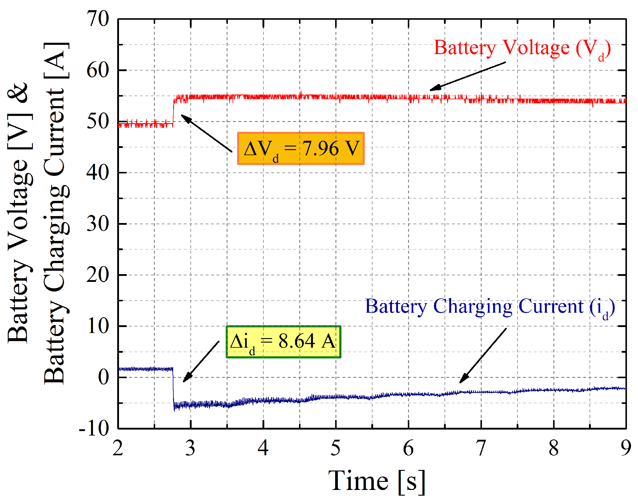
Figure 6,
Figure 7 and
Figure 8 show the results of the experiments for calculated specific duty ratio (0.78). According to
Figure 6, at 2.2 s, the regenerative braking has started, causing the voltage to jump from 48.8 V to 56 V. The output current value of the boosting converter at the starting of regenerative braking is measured as
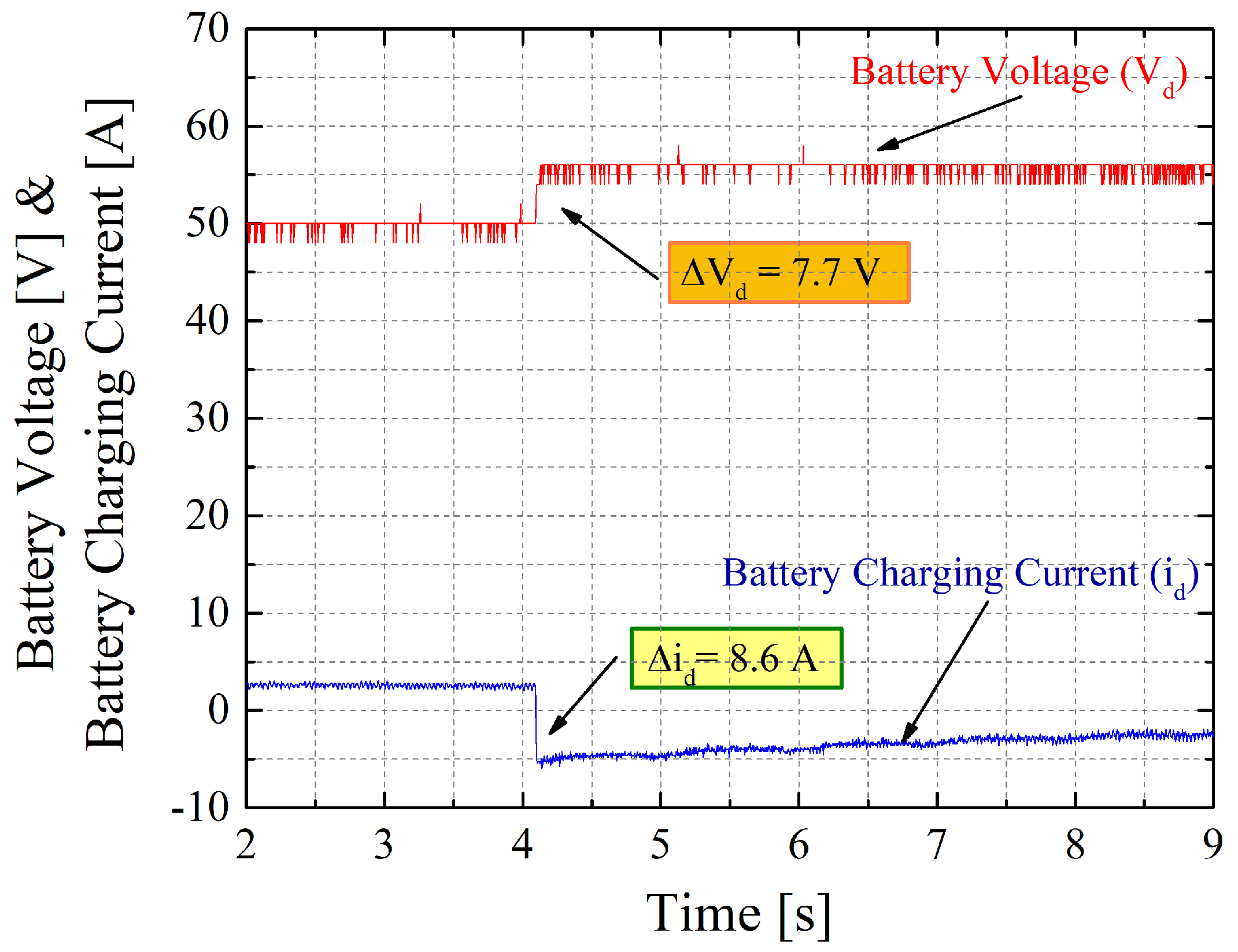
A. Note that a reversal of current occurs when the driver shifts from the inverter to boost converter operation. In this case, the total deceleration time is recorded as 120 s. The specific regenerative braking time is measured as 14.2 s. In Case-2, the temperature of the battery increases to 30
C by the heating controller. The internal resistance is measured as 0.837
. The voltage increases to 55.7 V for the specific duty ratio (0.78) in
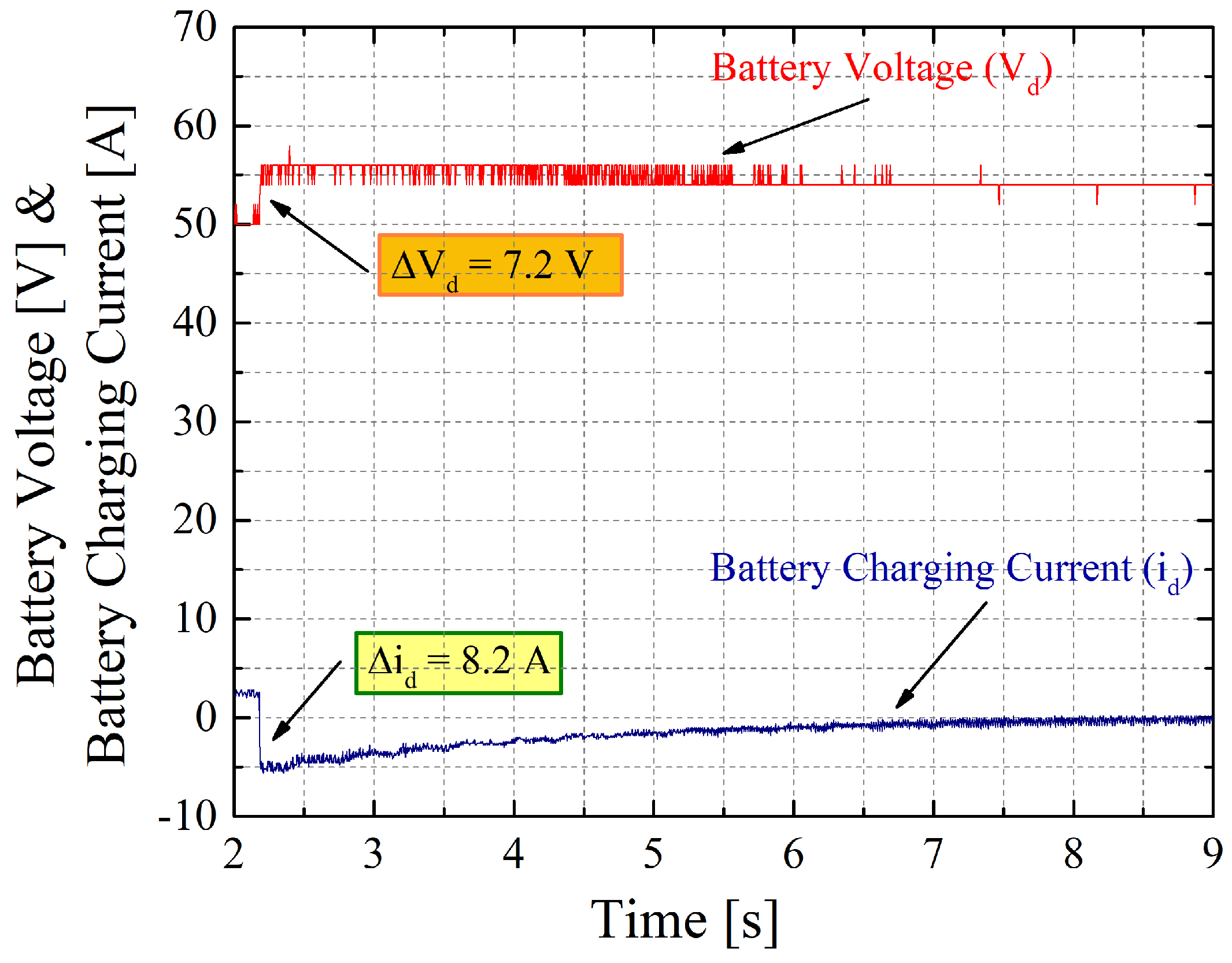
Figure 7. In
Figure 8, the voltage of the battery increases to 55.5 V for the regenerative braking at 35
C. As can be seen from the experimental results, it is determined that the regenerative braking performance increases for the certain values of the duty ratio. The experimental results for different temperatures and duty ratios are presented in
Table 3.
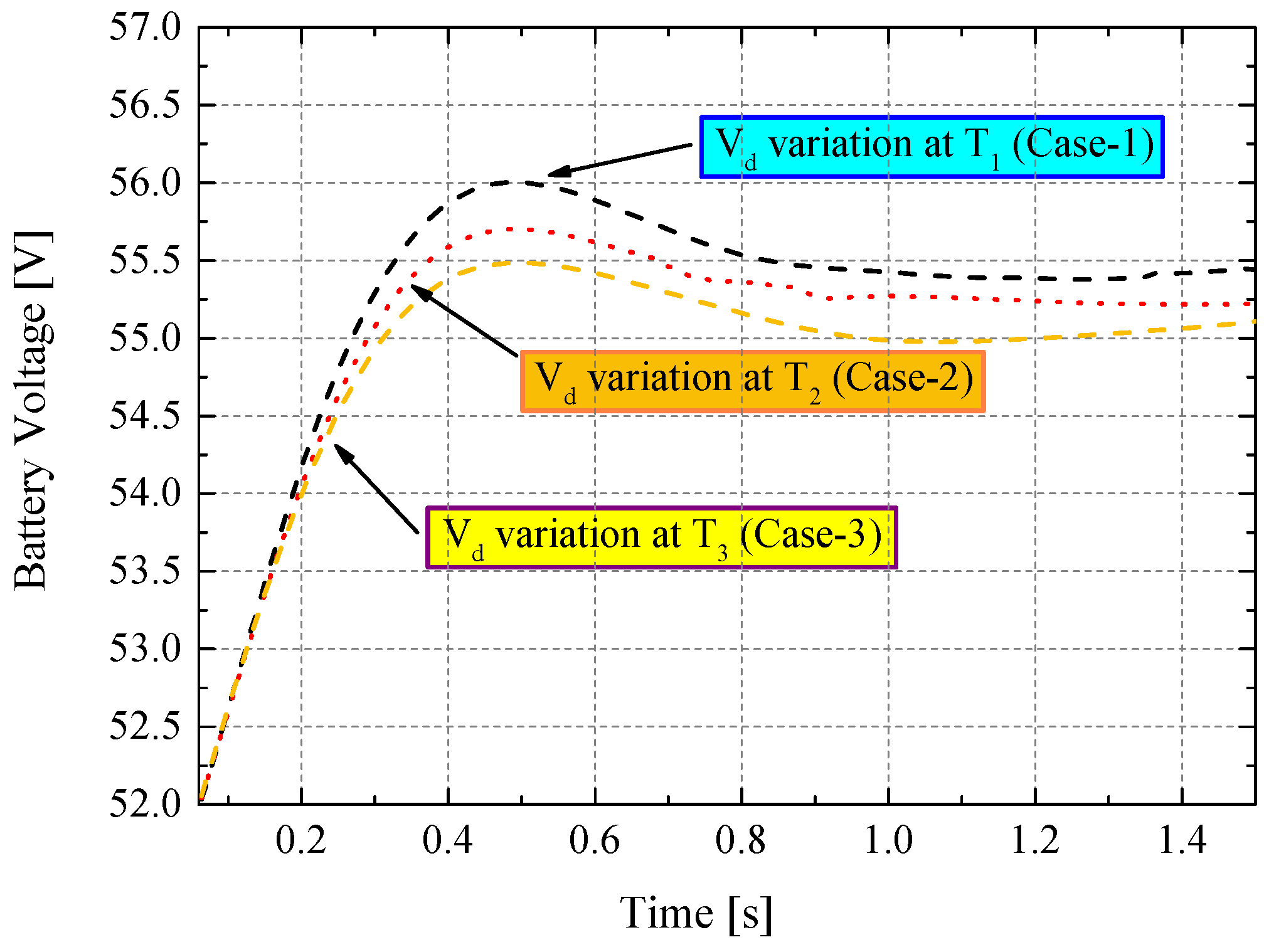
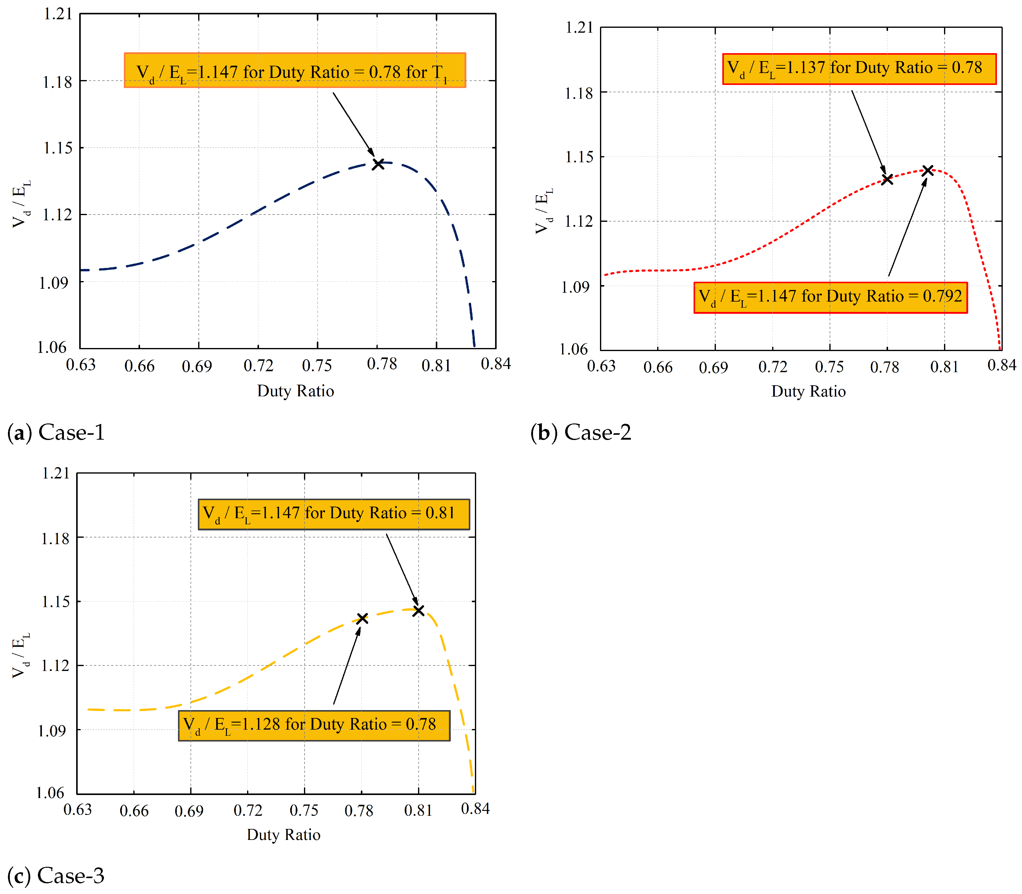
The most critical indication of the experiments is that the regenerative braking performance decreases dramatically if the calculated duty ratio remains unchanged despite varying temperatures. Thus, in order to recover the same amount of energy, 0.78 should be recalculated as 0.792 for 30 C and 0.81 for 35 C.
The electrical measurements are made at the battery terminals, so only the regenerated power and energy values are calculated, the charging efficiency which can be easily calculated by means of the non-ideal battery model is excluded. When all non-ideal variables and the battery temperatures in the energy recovery calculations are taken into consideration, 2.9 kWs of energy is regained as a result of the selected specific duty ratio. The recovered power calculation is performed by capturing the current and voltage variations in the dc-link during the active regenerative braking period. By integrating the product of the current and voltage values on the dc-link, the regenerated energy value is calculated.
In the no-load deceleration tests, the maximum recovered energy is 3.2 kWs. In Case-1, it can be seen that energy recovery is achieved with a high performance with a ratio of 2.9 kWs/3.2 kWs. Contrary to this, the energy recovery measurements have shown that in Case-2 and Case-3, 2.65 kWs and 2.47 kWs of energy obtained for 30
C and 35
C, respectively. Filtered voltage waveforms obtained during regenerative braking for Case-1, Case-2, and Case-3 are presented in
Figure 9. Instantaneous battery voltage risings are presented for the same duty ratio (0.78). When the same duty ratio (0.78) is applied, peak value variations of voltages are presented for
,
, and
temperatures for different scenarios. In
Figure 10, the conversion ratio (
) variation is shown for
,
, and
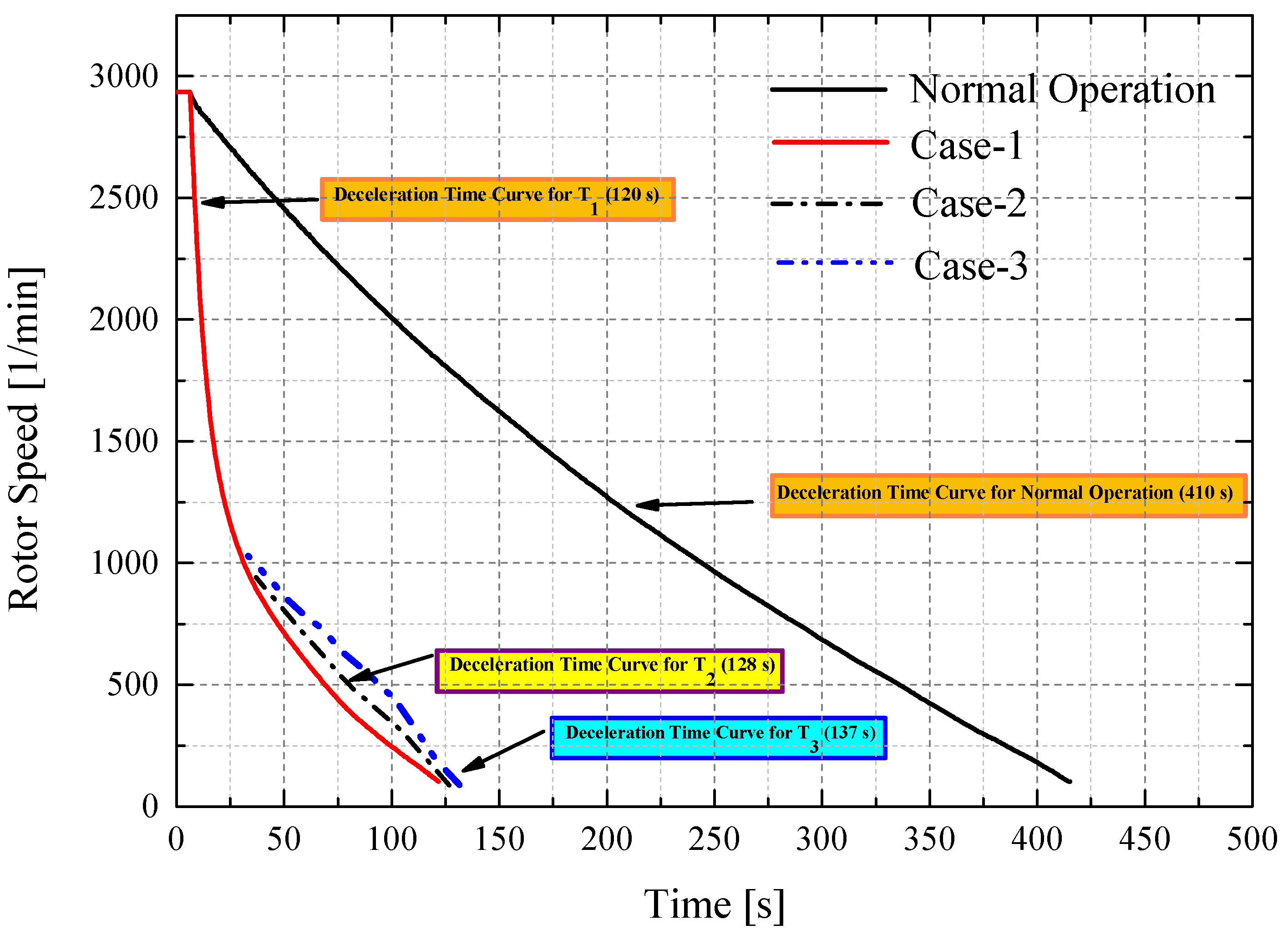
. The machine deceleration times, which are shown in
Figure 11, have been recorded as 128 s at temperature
, and as 137 s at temperature
. The performance expected from braking can be measured by the duration of the deceleration time. It is also possible to see how much braking power the vehicle requires to accomplish the expected deceleration time. When all non-ideal variables and battery temperature variation are taken into account, the regained energy amount is about 8.73% and the value of the calculated duty ratio in the control cycle is revealed.


