Abstract
In this paper, a method to improve the performance of PEMFCs using porous material as a flow channel baffle is proposed. The results show that PEMFCs with four porous baffles flow channels have better performance at high current density compared with the traditional flow channel. The structural parameters of the flow channel explored in this study include porosity, the thickness of the baffle and the number of baffles, and their influence on the performance of PEMFCs. Sensitivity analysis results show that the performance of the PEMFCs with the porous baffle channel is the most sensitive to baffle thickness, and the thickness and baffle could be appropriately adjusted. The number of plates and porosity of the baffle are adjusted to improve the performance of the PEMFCs.
1. Introduction
With the increase in environmental pollution and the shortage of fossil fuels, it has become urgent to find clean and recyclable energy sources to replace fossil energy [1,2]. Proton exchange membrane fuel cells (PEMFCs) are regarded as an essential energy source of the 21st century because of their high efficiency, cleanliness, and recyclability. PEMFCs have been used in many fields such as vehicles, portable power systems, and stationary power stations. However, increasing the power density of fuel cells is still a critical challenge that restricts the commercialization of PEMFCs.
Flow channel optimization to enhance mass transfer has been considered as an effective solution. Chen et al. [3] established a single-channel gas–liquid two-phase flow PEMFC model to study the effect of the channel cross-section on liquid water in porous media. The results show that compared with the square cross-section channel, the trapezoidal interfacial channel reduces the accumulation of liquid water in porous media to a certain extent and significantly improves the performance of PEMFCs. Wang et al. [4] studied the structural parameters of serpentine channels by establishing a three-dimensional numerical model. The results showed that the performance of PEMFCs was improved with the increase in serpentine curves’ number and channel width. Additionally, the performance of single-channel serpentine arrangement is better than that of dual-channel serpentine arrangement and three-channel serpentine arrangement. Korkischko et al. [5] established a single-channel PEMFC model with computational fluid dynamics (CFD) and studied the influence of the channel section on the PEMFC performance. The simulation results show that the optimized channel section has a higher current density and power density than the traditional rectangular channel, and the optimized channel improves the uniformity of the current density. Ferng et al. [6] proposed a 3D “whole-cell” CFD model to study the effects of different channel designs, including parallel channel, serpentine channel, single-path channel and multi-path channel, uniform depth channel, and step depth channel, on the performance of fuel cells. The research shows that the parallel channel with step depth design significantly improves the performance of PEMFCs.
Some studies have improved the performance of PEMFCs by adding obstacles in the flow channel. Fan et al. [7] added deflectors and baffles and studied the influence of geometric parameters of deflectors on the performance of fuel cells. The results show that the performance of the deflector was best at an included angle of 30°, 0.5 mm width and 6.0 mm pacing. The new flow channel enhances the diffusion of gas to the gas diffusion layer (GDL) and catalytic layer (CL), resulting in an increase in the reaction gas concentration and reaction speed in the CL. Snozdemira et al. [8] studied the influence of flow field blockage on the PEMFC performance and developed a PEMFC flow field with a blocked flow effect. CFD simulation results showed that rectangular and semicircular plugs increase the diffusion rate of reactants and improved the performance of the PEMFC.
The bionic channel [9,10] was proposed by studying the shape and structure of organisms. Su et al. [9] introduced tree fractals into the design of interdigital flow fields and found that the power density of PEMFCs based on tree fractal interdigital flow fields was 36.7% higher than that of the interdigital flow field. Chen et al. [10] established a PEMFC model with a wavy channel and optimized the PEMFC model by CFD. The simulation results show that the corrugated channel improved the performance of PEMFCs and the discharge of liquid water in the microporous layer. The optimum structural parameters of the channel were obtained, d, with a minimum depth of 0.45 mm and a minimum wavelength of 2 mm. Li et al. [11] established a wavy serpentine channel to improve the defect of a large inlet and outlet pressure difference of the traditional serpentine channel. PEMFCs with wavy serpentine channels were numerically simulated and verified by Fluent. The verification results show that the model is superior to the traditional serpentine channel in promoting the transport of cathode reactants and removing liquid water. Chen et al. [12] established a bionic flow channel based on the plant vein structure. The comparison between the fluent simulation and traditional serpentine flow channel show that the maximum current density of the bionic flow channel based on the plant vein structure is 34.6% higher than that of the traditional serpentine flow channel and had better performance. In order to solve the uneven distribution of materials under the ribs of the direct channel and the elimination of water in the GDL, Wang et al. [13] developed an auxiliary fishbone flow field model inspired by the fishbone. The simulation results of the three-dimensional model show that the uniformity of the new flow field and the saturation distribution of the uniformity in the reactant were better than that of the straight channel. Yan et al. [14] designed the geometry of two three-dimensional flow channels and verified the numerical model through the experiments. One structure is a waveform channel that promoted oxygen convection, increased the oxygen supply, and generated vortices, where the vortices discharged the water accumulated in the GDL through inertia. The other structure was a wavy channel with gradient depth which increased the fluid velocity along the channel, overcame severe hypoxia, flooded the downstream area, and made the current distribution more uniform. Cai et al. [15] et al. established a three-dimensional non-isothermal PEMFC model using COMSOL 5.3, and studied the influence of a squid finlike flow channel on the performance of the PEMFC. The results show that the new channel significantly reduces the pressure drop and increases the diffusion rate of reactants. Inspired by human lungs and leaf veins, Srinivasa et al. [16] established an interdigital bionic flow channel. The experimental results show that the new blade channel had the advantages of a three-channel serpentine channel. With higher power density, the new interdigital channel has a higher power density than the new blade channel.
In order to make the channel design simpler and increase the performance of PEMFCs, a channel with porous baffles was proposed. In this study, a 3D model of a PEMFC was established in COMSOL 5.5, and the porous media baffle was used in the flow channel, as shown in Figure 1. The effects of this new design on the performance of PEMFCs were studied, including the average current density and voltage. The results were compared with those of a basic straight channel. In addition, the parameter sensitivity of the channel was analyzed.
Figure 1.
The 3D model of PEMFCs with the four porous baffles.
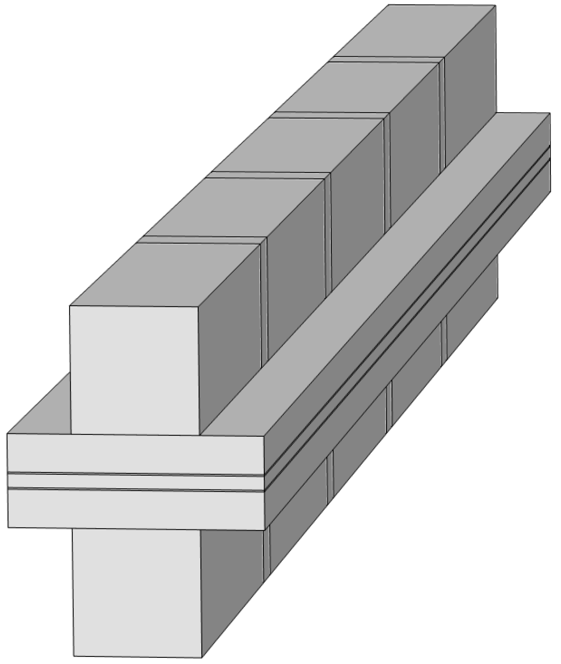
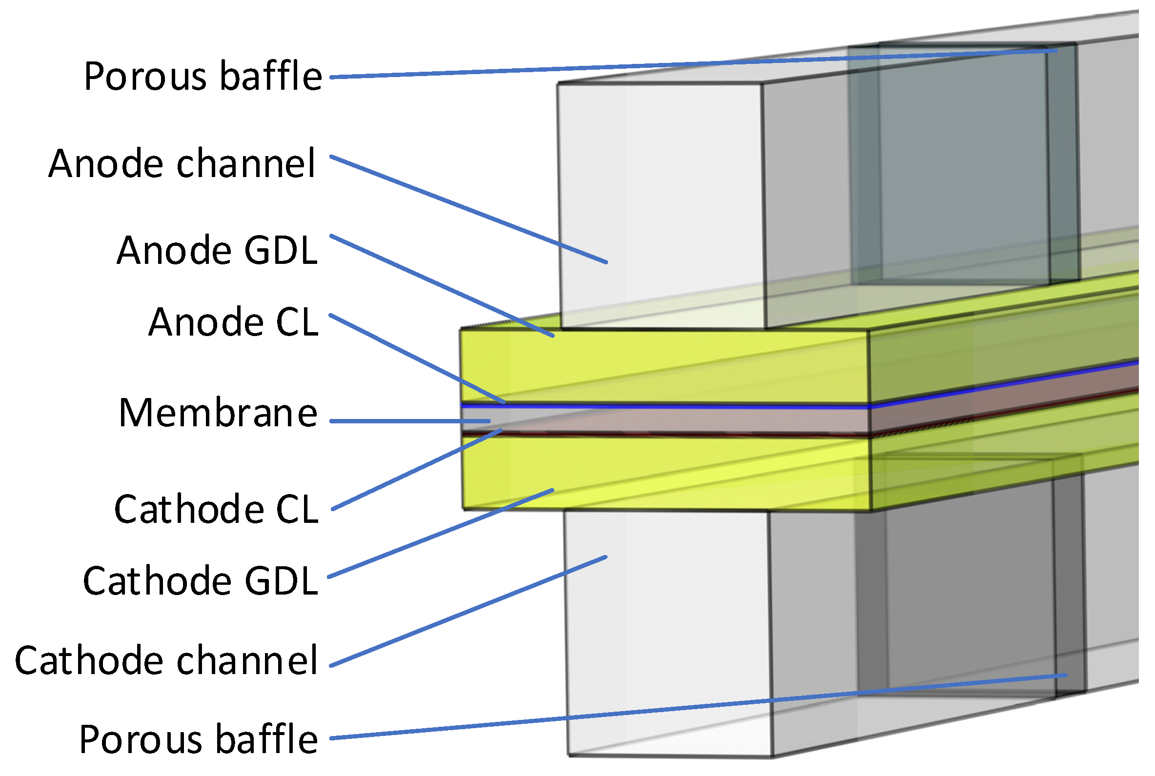
2. Geometric Description
The geometry of the PEMFCs with the porous baffle is shown in Figure 2 and the geometric parameters and operating parameters are shown in Table 1. The baffle was made of a porous material with a thickness equal to the cross-section of the flow channel, completely blocking the whole flow channel, and the gas in the flow channel can only complete material transport through the pores of the baffles and GDL.
Figure 2.
Geometric diagram of the PEMFCs with the porous baffles.
Table 1.
Geometric and operating parameters.
3. Establishment of Numerical Model
3.1. Model Assumptions
A 3D, isothermal steady-state PEMFC model was established to verify the proposed channel design. As shown in Figure 1, in order to obtain the effect of the channel with the porous baffles on the performance of the PEMFC, a basic straight channel was used for comparison. To simplify the model, the following assumptions were made:
- (1)
- The reaction gas is the ideal gas equation;
- (2)
- The gas flow in the PEMFC is laminar flow;
- (3)
- The porosity, conductivity, and permeability of the GDL and CL is isotropic;
- (4)
- The contact resistance between the layers is ignored;
- (5)
- Gravity is ignored;
- (6)
- Only protons can pass through the proton exchange membrane;
- (7)
- The system is ideal and binary.
3.2. Governing Equations
In order to establish the PEMFC model, the mass conservation equation, the Brinkman equations, the transport equations of concentrated species, the multi-phase flow multi-matter equation, the water conservation equation in membrane, and the secondary current density equation were established.
Mass conservation equation:
The Brinkman equation in porous media:
The transport equation of concentrated species:
where is expressed by Maxwell–Stefan diffusion:
where is the Maxwell–Stefan diffusion coefficient. Under assumption 7, is expressed as follows [17]:
where Dik is the Fick’s diffusion coefficient, The correlation diffusion coefficient was obtained from reference [15].
In Equation (4), is the diffusional driving force and was expressed as follows:
The water conservation equation in the membrane:
where is the ionized water flux and is expressed as follows:
The second current density equation:
The parameters used in the equations are listed in Table 1 and the source phases of each equation are listed in Table 2.
Table 2.
Source terms in governing equations.
3.3. Boundary Design
The geometric model of the PEMFC is shown in Figure 1. In the flow direction of the PEMFC, the boundaries of the GDL, CL, and membrane adopted symmetrical boundary conditions. Except for the inlet and outlet boundary of the channel, wall conditions were adopted. At 100% humidity, hydrogen and air flowed in the same direction and entered the anode channel and cathode channel, respectively. The gas temperature at the inlet and the temperature of the surrounding wall were set to their operating temperature. The working pressure was set to limit the anode and cathode outlet boundaries. According to the ideal gas equation, the inlet velocity was calculated as follows:
The material fraction at the inlet inflow, ωi, can be obtained from the mole fraction, , of the substance as follows:
The cathode is applied with voltage and the anode is grounded at the boundary of the corresponding electrode, which is used to solve the secondary current density.
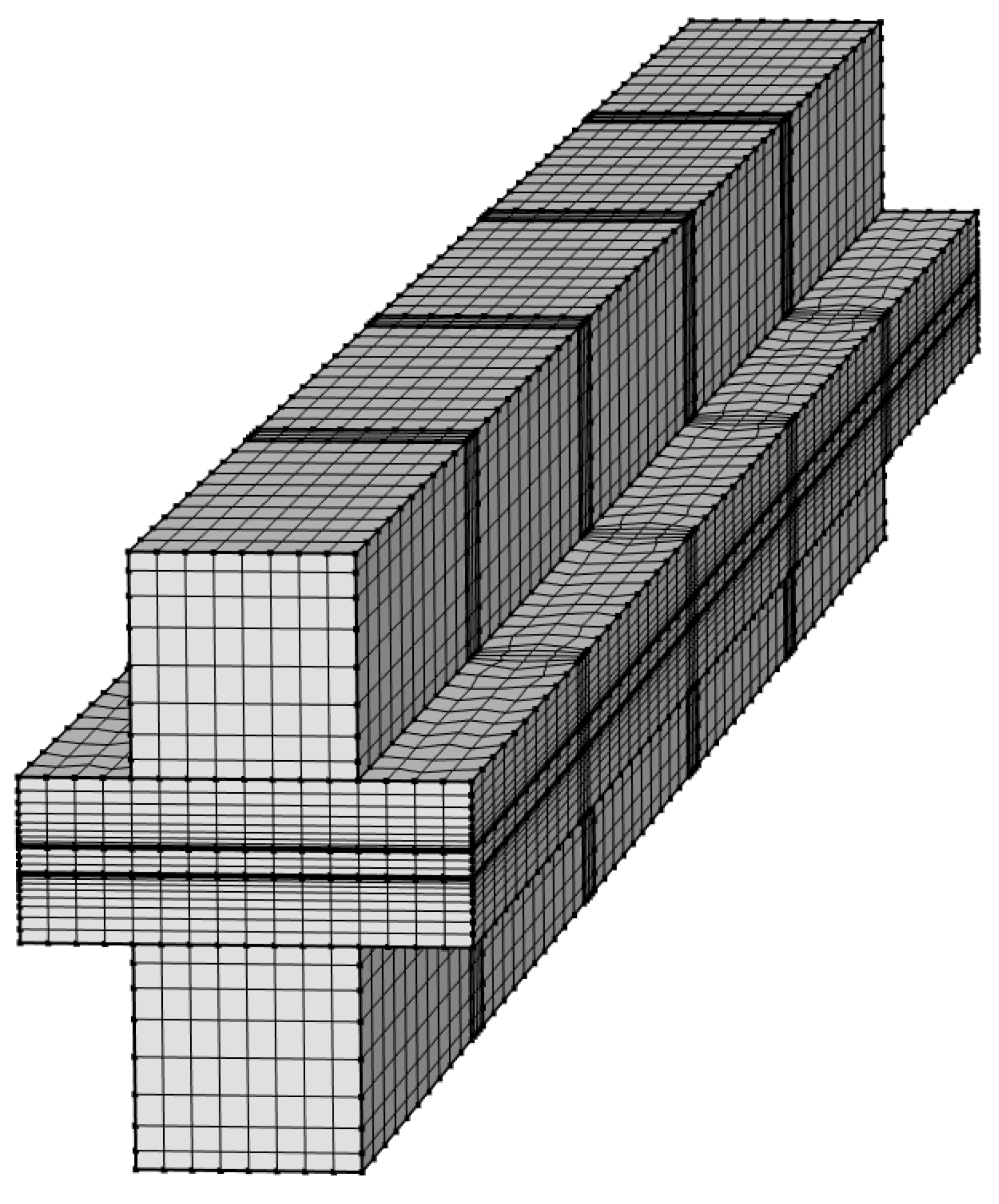
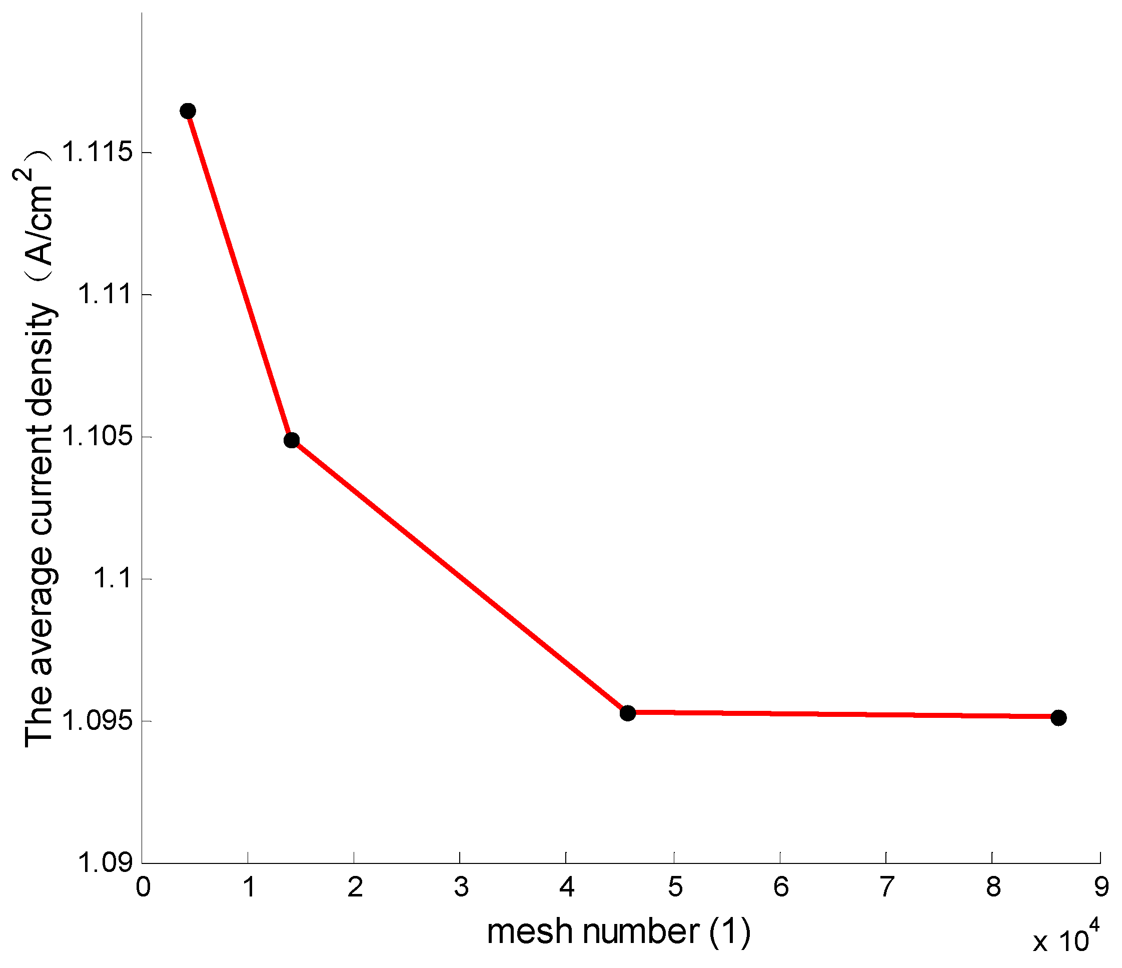
3.4. Numerical Simulation
The mathematical model is established using the multi-physical field simulation software COMSOL 5.5, and the aforementioned coupled equations were iteratively solved by the finite volume method. To test grid independence, the model was divided into four different grids (4368, 14,112, 45,696, and 86,016). As shown in Figure 3, when the voltage is 0.4 V, the difference between the current density calculation results for the 45,696 and 86,016 grid cells is less than 0.1%, which has little impact on the results. The calculation model of the porous baffle PEMFC is shown in Figure 4. In order to ensure the accuracy of the calculations, the mesh density is also different due to the different thicknesses of each component. The model takes 30 min for the calculations on the 2.4 GHz workstation with 64 RAM.
Figure 3.
Mesh validation.
Figure 4.
Computational grids for the PEMFC calculation.
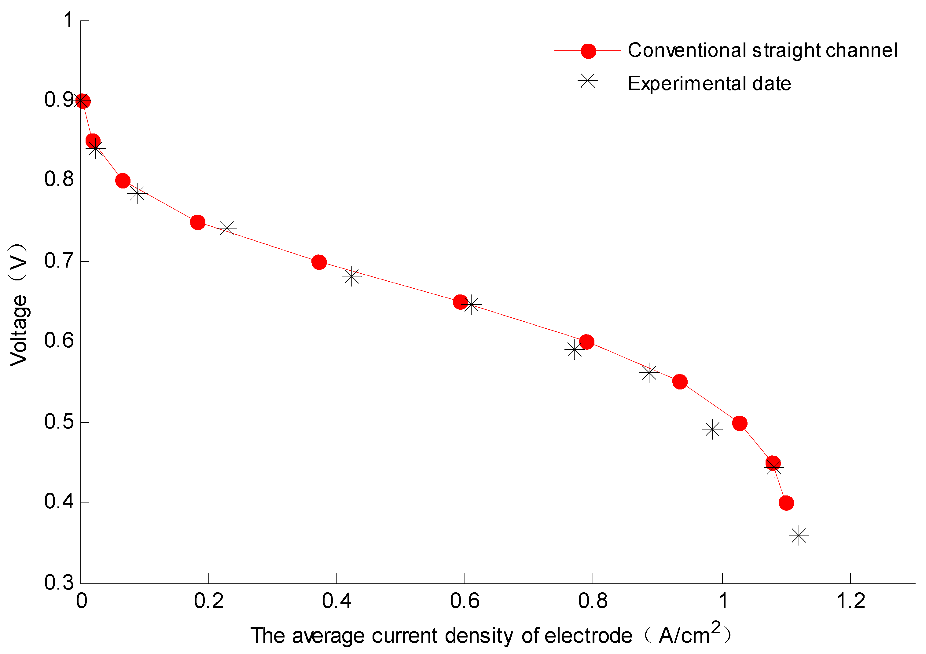
3.5. Model Validation
In order to verify the effectiveness of the numerical model, the anode and cathode channels were set to basic straight channels without baffles; the polarization curve obtained by the simulation model was compared with the experimental data obtained from Wang et al. [18], as shown in Figure 5. The results are consistent and the maximum error between the two was found to be 4.04%, at the average current density of 0.982 (A/cm2). Therefore, the model was verified by experiments.
Figure 5.
Model validation: comparison between simulation results of the straight channel model and experimental results obtained from Wang [18].
3.6. Description of New Channel
The new channel is a channel with porous baffles which are evenly distributed in the channel—the geometric parameters of which are shown in Table 3.
Table 3.
The geometric parameters.
4. Results and Analysis
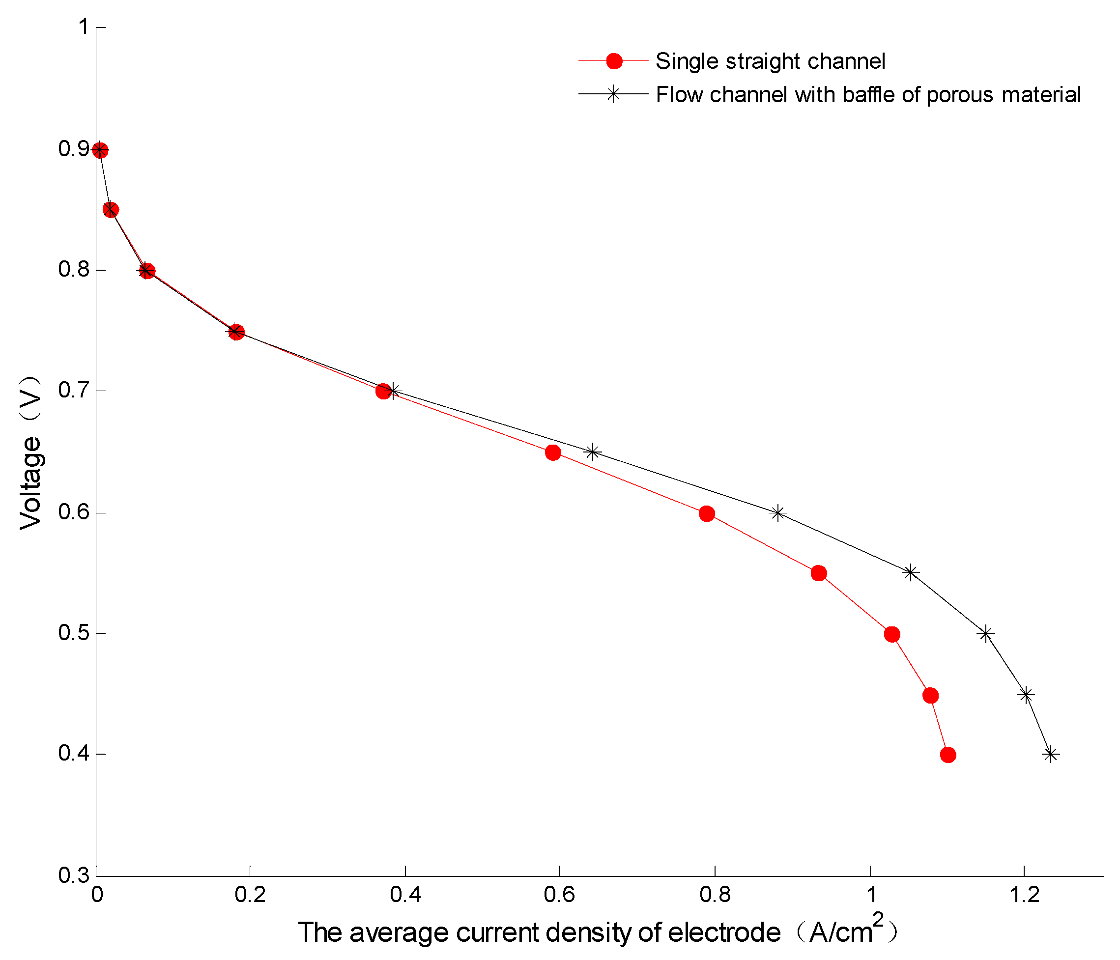
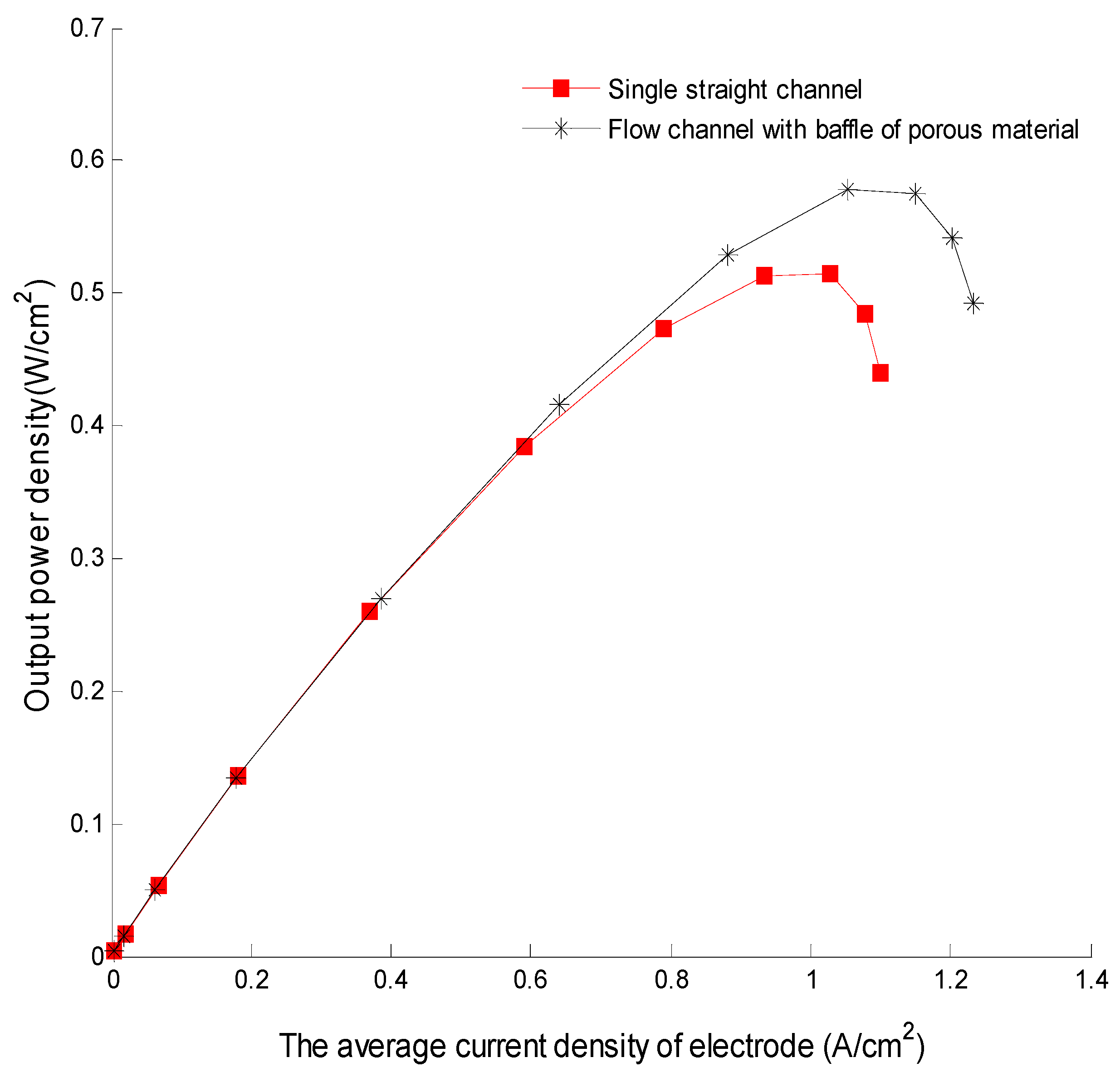
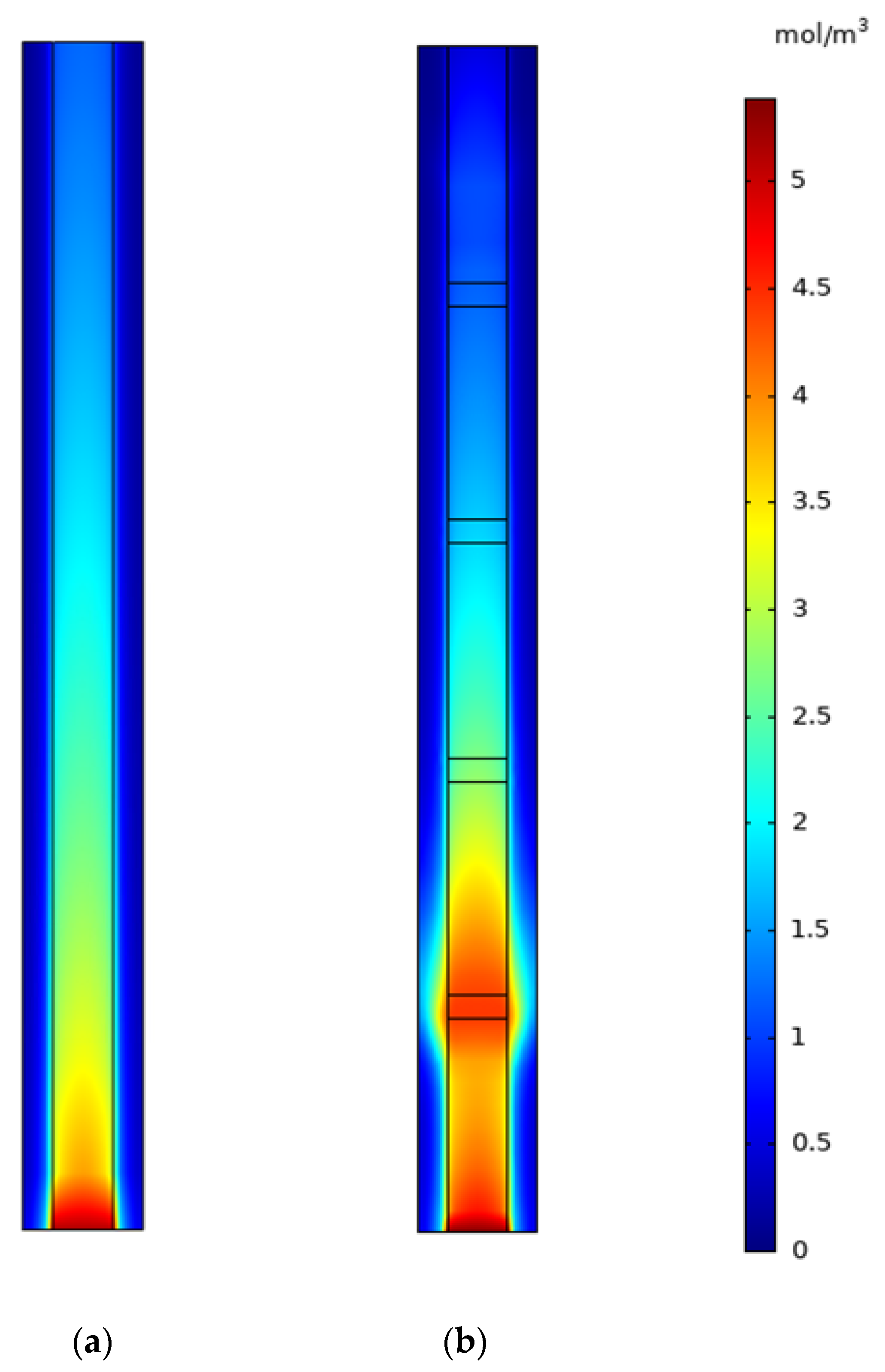
4.1. Comparison with Two Types of Channels
Figure 6 shows that the comparison of the polarization curves between the PEMFC with a single straight channel and the PEMFC with a channel with four porous baffles. It was found that the performance of the channel with four porous baffles was not superior to that of the single straight channel at low current density. However, the average current density of the PEMFC with the porous flow channel was higher than that of the PEMFC with the single straight channel at a high current density. At 0.4 V, the average current density of PEMFCs increases from 1.105 A/cm2 to 1.224 A/cm2, i.e., an increase of 12.8%.
Figure 6.
The comparison of the polarization curves between the PEMFC with a straight channel and the PEMFC with a straight channel and four porous baffles.
The comparison of power density curves between the PEMFC with a straight channel and the PEMFC with a channel with four porous baffles is shown in Figure 7. With the increase in the current density, the influence of the flow channel with the porous baffle on the performance of the PEMFC gradually increases and the maximum power density of the PEMFC with the four porous baffles increases from 0.5139 (W/cm2) to 0.5789 (W/cm2), i.e., an increase of 12.7%.
Figure 7.
Comparison of power density curves between the PEMFC with a straight channel and the PEMFC with straight channel and four porous baffles.
Figure 8 shows the two-dimensional cloud diagram of the GDL cathode oxygen concentration distribution at 0.4 V in the single channel model and the channel model with four porous baffles. Obviously, the oxygen concentration in the channel is the highest at the entrance and decreases with the progress of the chemical reaction. Additionally, the oxygen concentration in the contact area between the GDL and the runner is much higher than that under the rib. Compared with the straight channel, the porous blockage in the channel led to higher oxygen concentration and significantly improved the local distribution of oxygen.
Figure 8.
Two-dimensional cloud diagram: oxygen concentration distribution of (a) the GDL cathode in a straight channel model and (b) the GDL cathode in a straight channel model with four porous baffles at 0.4 V.
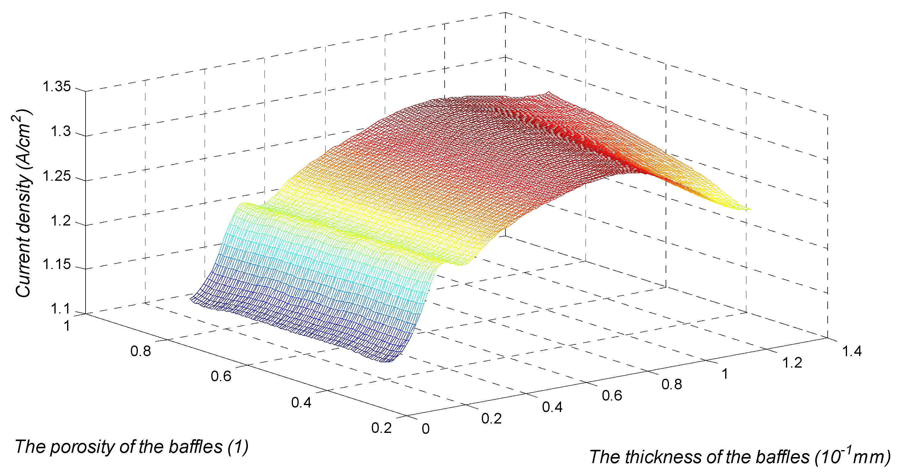
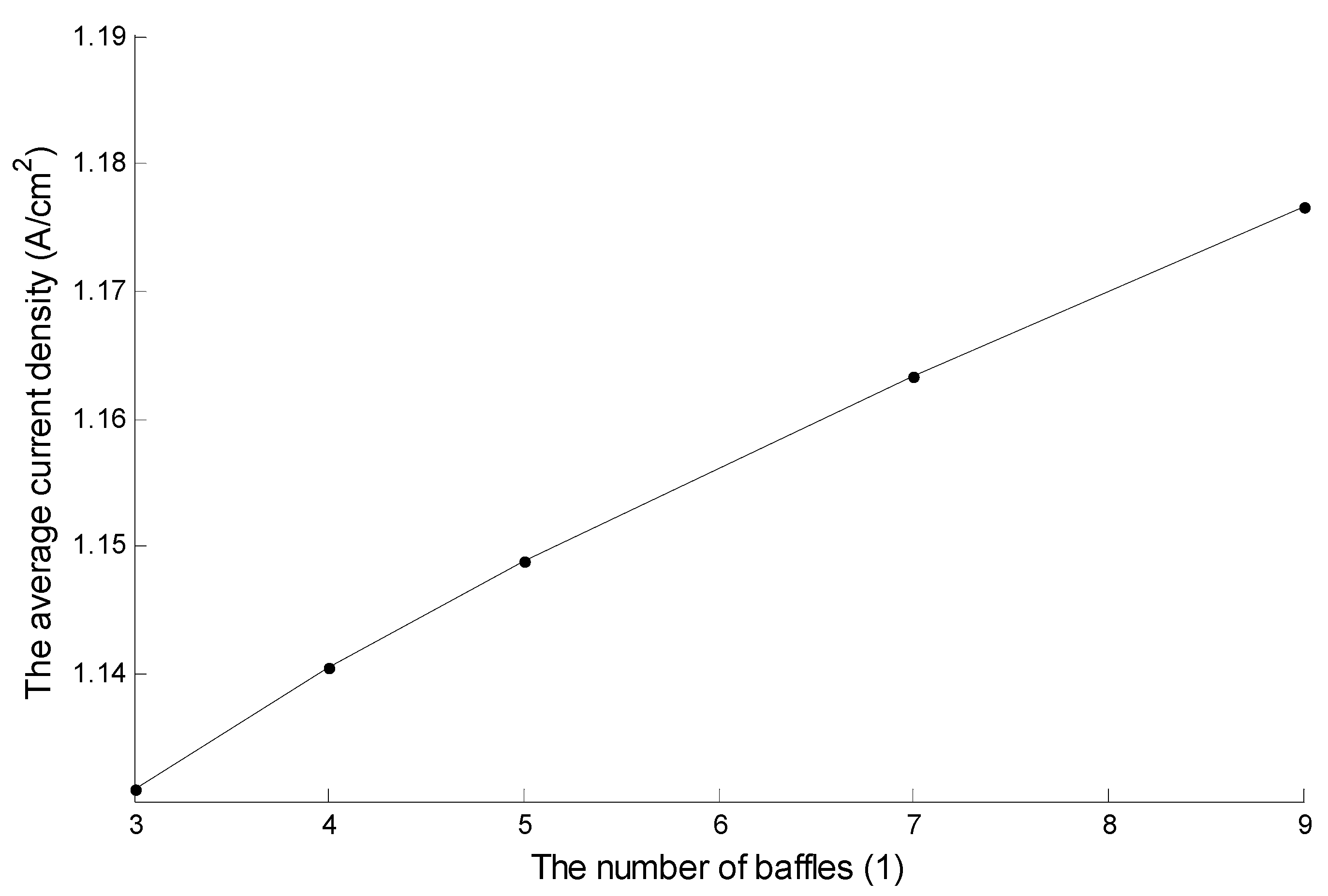
4.2. Sensitivity Analysis of the New Channel Parameters
Figure 9 shows the variation of the average current density with the thickness and baffle porosity of the PEMFCs with four baffles at 0.4 V. The influence of the baffle porosity on the average current density of the PEMFC varies in function of thickness. When the thickness of the baffle is 1.28 mm, and the porosity of the baffle increases from 0.3 to 0.8, the average current density of the PEMFC increases from 1.238 A/cm2 to 1.298 A/cm2, i.e., an increase of 7.428%. When the porosity of the baffle is constant, the influence of the baffle thickness on the performance of the PEMFC increases and decreases twice, forming two peaks and valleys. At a voltage of 0.4 V and baffle porosity of 0.5, the first peak of the average current density is at 1.239 A/cm2, at a thickness of 0.2497 mm, whilst the second peak is at 1.308 A/cm2, at a thickness of 0.8 mm. The valley is at 1.232 A/cm2 and at a thickness of 0.3224 mm.
Figure 9.
Variation of average current density with the thickness and baffle porosity of the PEMFC with four baffles at 0.4 V.
Figure 10 shows the effect of the number of baffles on the performance of the PEMFC for a porosity of 0.3, with a baffle thickness of 0.8 mm, and a voltage of 0.4 V. Figure 10 shows that the performance of the PEMFC increased approximately linearly with the increase in the number of baffles. When the number of baffles increased from 3 to 9, the average current density of PEMFCs increased from 1.1301 A/cm2 to 1.1766 A/cm2, i.e., an increase of 4.11%.
Figure 10.
Effect of the number of baffles on the performance of PEMFC when the porosity is 0.3, the baffle thickness is 0.8 mm, and the voltage is 0.4 V.
5. Conclusions
In this paper, a porous baffle channel model of PEMFC is proposed, and a 3D simulation verifies the performance of channel PEMFC with the porous baffles. The influence of the straight channel structure parameters of the porous baffles on the performance of PEMFC was investigated. The results of the simulation and discussion are as follows:
- Compared with traditional single-channel PEMFCs, the PEMFC with four porous baffles was found to be better at high current density. At 0.4 V, the average current density of the PEMFC increased by 12.8% and the maximum power density increased by 12.7%.
- Porous materials were used as baffles to improve the uniformity of the local distribution of oxygen and the concentration under the ribs where the baffles were located, thus improving the performance of the PEMFC.
- The influence of the structure parameters of the porous baffles on the performance of the PEMFC can be described as follows: as the porosity of the baffle and the number of baffles increase, the performance of the PEMFC gradually increases. With the increase in the thickness of the baffle, the performance of the PEMFC shows a trend of increasing and then decreasing, resulting in two peaks.
Author Contributions
Conceptualization, Y.S.; writing—review and editing, C.C.; visualization, M.W.; supervision, S.L.; project administration, D.X.; funding acquisition, D.X. All authors have read and agreed to the published version of the manuscript.
Funding
This work was supported by the Natural Science Foundation of Zhejiang Province LQ20E060012.
Institutional Review Board Statement
This study did not involve humans or animals.
Informed Consent Statement
This study did not involve humans.
Data Availability Statement
This study did not report any data.
Conflicts of Interest
The authors declare no conflict of interest.
Nomenclature
| The porosity | |
| The density (Kg/m3) | |
| The pressure (Pa) | |
| The mass fraction of substance | |
| Two-phase conversion coefficient (1/s) | |
| The geometrical area (m2) | |
| Relative humidity | |
| Velocity (m/s) | |
| The source | |
| The potential | |
| The mole fraction of substance | |
| μ | Viscosity (Pa/s) |
| The flux (mol/(m2 s)) | |
| Subscripts | |
| The substance type, | |
| k | The substance type, |
| The computational domain, GDL or CL | |
| j | Two-phase water, liquid or gas. |
| The membrane | |
| The channel | |
| The electrolyte potential | |
| The potential | |
| a | The anode |
| The ionic water | |
| The cathode | |
| The liquid water | |
| The maximum value | |
| The condensation coefficient | |
| evap | The evaporation coefficient |
| The saturation value | |
| eff | The effective value |
| A mixture of N substances | |
References
- Wang, Y.; Chen, K.S.; Mishler, J.; Cho, S.C.; Adroher, X.C. A review of polymer electrolyte membrane fuel cells: Technology, applications, and needs on fundamental research. Appl. Energy 2011, 88, 981e1007. [Google Scholar] [CrossRef] [Green Version]
- Wilberforce, T.; Alaswad, A.; Palumbo, A.; Dassisti, M.; Olabi, A.G. Advances in stationary and portable fuel cell applications. Int. J. Hydrog. Energy 2016, 41, 16509–16522. [Google Scholar] [CrossRef] [Green Version]
- Chen, Z.; Yang, X.; Hu, X.; Wang, C. Optimization of channel structure for proton exchange membrane fuel cells based on a three-dimensional two-phase flow model. Int. J. Energy Res. 2021, 45, 8794–8809. [Google Scholar] [CrossRef]
- Wang, X.D.; Duan, Y.Y.; Yan, W.M.; Peng, X.F. Local transport phenomena and cell performance of PEM fuel cells with various serpentine flow field designs. J. Power Sources 2008, 175, 397–407. [Google Scholar] [CrossRef]
- Korkischko, I.; Carmo, B.S.; Fonseca, F.C. Shape Optimization of PEMFC Flow-channel Cross-Sections. Fuel Cells 2017, 17, 809–815. [Google Scholar] [CrossRef]
- Ferng, Y.; Su, A. A three-dimensional full-cell CFD model used to investigate the effects of different flow channel designs on PEMFC performance. Int. J. Hydrog. Energy 2007, 32, 4466–4476. [Google Scholar] [CrossRef]
- Fan, L.H.; Niu, Z.Q.; Zhang, G.B.; Jiao, K. Optimization design of the cathode flow channel for proton exchange membrane fuel cells. Energy Convers. Manag. 2018, 17, 1813–1821. [Google Scholar] [CrossRef]
- Ozdemira, S.N.; Taymaz, I. Numerical investigation of the effect of blocked gas flow field on PEM fuel cell performance. Int. J. Environ. Sci. Technol. 2021, 18, 3581–3596. [Google Scholar] [CrossRef]
- Su, Y.J.; Lu, C.D.; Wu, M.G. Mass transfer performance analysis of PEMFC based on tree-like fractal flow field. Power Supply Technol. 2016, 040, 1367–1371. [Google Scholar]
- Chen, X.; Yu, Z.; Yang, C.; Chen, Y.; Jin, C.; Ding, Y.; Li, W.; Wan, Z. Performance investigation on a novel 3D wave flow channel design for PEMFC-Science Direct. Int. J. Hydrog. Energy 2021, 46, 11127–11139. [Google Scholar] [CrossRef]
- Li, W.K.; Zhang, Q.L.; Wang, C.; Yan, X.H.; Shen, S.Y.; Xia, G.F.; Zhu, F.J.; Zhang, J.L. Experimental and numerical analysis of a three-dimensional flow field for PEMFCs. Appl. Energy 2017, 195, 278–288. [Google Scholar] [CrossRef]
- Chen, T.; Liu, S.L.; Gong, S.C.; Wu, C.Q. Development of bipolar plates with different flow channel configurations based on plant vein for fuel cell. Int. J. Energy Res. 2013, 37, 1680–1688. [Google Scholar] [CrossRef]
- Wang, Y.; Si, C.; Qin, Y.; Wang, X.; Fan, Y.; Gao, Y. Bio-inspired design of an auxiliary fishbone-shaped cathode flow field pattern for polymer electrolyte membrane fuel cells. Energy Convers. Manag. 2021, 227, 113588. [Google Scholar] [CrossRef]
- Yan, X.; Guan, C.; Zhang, Y.; Jiang, K.; Wei, G.; Cheng, X.; Shen, S.; Zhang, J. Flow field design with 3D geometry for proton exchange membrane fuel cells. Appl. Therm. Eng. 2019, 147, 1107–1114. [Google Scholar] [CrossRef]
- Cai, G.; Liang, Y.; Liu, Z.; Liu, W. Design and optimization of bio-inspired wave-like channel for a PEM fuel cell applying genetic algorithm. Energy 2020, 192, 116670.1–116670.11. [Google Scholar] [CrossRef]
- Badduri, S.R.; Srinivasulu, G.N.; Rao, S.S. Influence of bio-inspired flow channel designs on the performance of a PEM fuel cell. Chin. J. Chem. Eng. Engl. Ed. 2020, 28, 824–831. [Google Scholar] [CrossRef]
- Hoteit, H. Modeling diffusion and gas–oil mass transfer in fractured reservoirs. J. Pet. Sci. Eng. 2013, 105, 1–17. [Google Scholar] [CrossRef]
- Wang, L.; Husar, A.; Zhou, T.; Liu, H. A parametric study of PEM fuel cell performances. Int. J. Hydrog. Energy 2003, 28, 1263e72. [Google Scholar] [CrossRef]
Publisher’s Note: MDPI stays neutral with regard to jurisdictional claims in published maps and institutional affiliations. |
© 2021 by the authors. Licensee MDPI, Basel, Switzerland. This article is an open access article distributed under the terms and conditions of the Creative Commons Attribution (CC BY) license (https://creativecommons.org/licenses/by/4.0/).